

Page 1

Model 9120, 9121 & 9122
Instruction Manual
SINGLE OUTPUT PROGRAMMABLE DC POWER SUPPLY
Page 2

Table of contents
General Information ……………………………………………. 3
Features …………………………………………………..……… 5
Local Mode Operation ………………….……………………….. 7
Front panel description ……………………………………………. 7
Memory key ………………… ……………………………………. 7
Storing states in front panel mode ………………………………… 10
Recall key …………………………………………………………. 12
Recalling states in front panel mode ……………………………… 14
Limit key ………………………………………………………….. 15
Modes of operation ……………………………………………….. 16
Constant current operation ………………………………………... 18
Constant voltage operation ………………………………………. .. 20
On / Off key ……………………………………………………….. 22
Remote / Local key ………………………………………………... 23
Errors / Calibrate key …………………………………………… … 25
Calibration Overview ……………………………………………. 28
Calibration security code ……………………………………... ... 28
Unsecure procedure for calibration …………………………….… 29
Hardware unsecure procedure for calibration ……………………. 32
Calibration Procedure …………………………………………… 34
Voltage Calibr ation Procedure ……………………………………. 35
Volt Zero Scale Calibration ……………………………………….. 35
Volt Full Gain Calibration ………………………………………... 36
OVP Calibration …………………………………………………… 37
Current Calibration Procedure …………………………………….. 38
Current Zero Scale Calibration ……………………………………. 38
Current Full Gain Calibration …………………………………….. 39
OVP / Secure key ………………………………………………….. 41
Programming OVP in front panel mode …………………………. 44
Clearing OVP condition …………………………………………… 46
Rear panel description ………………………………………… …… 50
Remote Interface ……………………………………..………….. 51
SCPI Commands …………………………………………………. 52
SCPI Commands Overview ………………………………………. 54
DISPlay Subsystem ……………………………………………….. 54
1
Page 3

Table of contents
OUTPut Subsystem ………………………………………………… 55
SYSTem Subsystem ……………………………………………….. 55
SOURce Subsystem ……………………………………………….. 56
MEASure Subsystem ………………………………………………. 62
TRIGger Subsystem ………………………………………………… 63
Non_SCPI commands ………………………………………………. 67
IEEE 488.2 commands ……………………………………………... 68
SCPI Status Registers ……………………………………………….. 70
Error Messages …………………………………………………… 74
Command Errors …………………………………………………… 74
Execution Errors …………………………………………………… 76
Device-specific Errors ……………………………………………... 76
Self-test Errors …………………………………………………….. 77
Calibration Errors …………………………………………………. 79
Technical Specifications ……………………………………….… 82
Supplemental Characteristics ……………………………………… 86
Programming Ranges ………………………………………………. 88
Reset Values ………………………………………………………... 89
Interface Cable ……………………………………………………… 90
Warranty Information ……………………………………….… 91
Service Information ………………………………………….… 93
2
Page 4

General Information
Single output programmable DC power suppl ies.
Output voltage is: 0 to 30.0 V for Model 912 0
0 to 20.0 V for Model 912 1
0 to 60.0 V for Model 9122
Output current is: 0 to 3.00 A for Model 9120
0 to 5.00 A for Model 9121
0 to 2.50 A for Model 9122
The power supply can be locally or remote controlled.
Interfaces: RS232 (Standard)
The commands available in remote interface mode are
• SCPI (Standard Commands for Programmable Instruments) commands
(SCPI 99 standard)
Page 5

4
Page 6

Features
• Constant Voltage / Constant C urrent modes of operation
This power supply can operate in either constant voltage or constant current
modes. The passing from one mode of operation to another is automatic.
The active mode of operation is indicated using two indicators:
CV – constant voltage mode of operation
CC – constant current mode of operation
• Overvoltage protection
Overvoltage protection circuit can be locally or remote activated.
When it is active, ovp indicator is displayed.
• Output on / off
When output off, output voltage is 0 V.
This permits a zero output voltage without switching off the power supply.
• 100 operating states storage
States are identified by location number and name.
Stored parameters are: voltage limit, voltage step, overvoltage protection level,
state of overvoltage protection circuit, current limit, current step, voltage trigger
value, current trigger value, trigger delay value, trigger source, stored state
name, state of display, output state.
After power on, state 0, named power_up will become the current operating
state.
• error messages
Errors are stored in a 20 locations FIFO (first in first out) queue.
They can be read in local mode (error number returned) or in remote operation
mode (error number and definition returned).
Every error is announced by a beep and the err indicator.
5
Page 7

6
Page 8
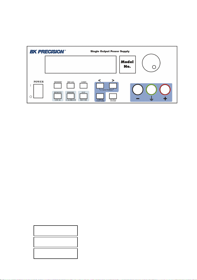
Local mode operation
Front panel keys description
Memory key
Note: Memory location 00 is the “Power-up” state. When the unit is powered
up, the power supply will set itself to the settings stored in location 00.
Note: If you press the Recall button while turning the power on, the power
supply will power up using memory location 01 parameters.
This button is used to store power supply’s current operating state in nonvolatile memory. Using this function all operating parameters are saved so they
can be recalled. You can store 100 differe nt operating states in the non-volatile
memory.
Stored parameters are: voltage limit, voltage step, overvoltage protection level,
state of overvoltage protection circuit, current limit, current step, voltage trigger
value, current trigger value, trigger delay value, trigger source, stored state
name, state of display, output state.
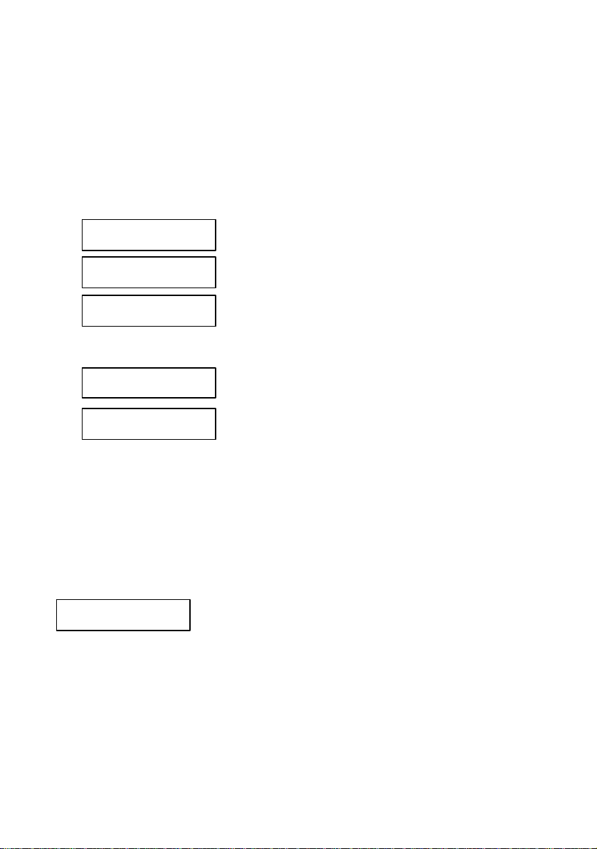
By pressing Memory key, you enter in Memory menu.
By turning the knob following options will be displayed:
Store State
Name State
Exit
7
Page 9

Options are selected by pressing Memory key when the desired option is
displayed.
Memory menu overview
Store State
Store State option will store the current operating state without setting a
name for this state. The state will be identified using location number in
non-volatile memory and the default name.
By pressing Memory key, state number and state name are displayed in
ascending order by turning the knob.
In this menu, Exit option is available, too. In this case, you leave the store
operation mode, without changing anything. No Change message will be
displayed and the power supply returns to the previous state (the state
before entering Memory menu).
The states are scrolled using the knob.
A location is selected by pressing Memory key. If the location you choose
is already written, it is overwritten (without an y warning) with the current
state parameters, but the name (the set one or the default one remains
unchanged). Done message will be displayed.
Name State
Name State option allows you to set a name for the current state (you can
also change a name set before).
The state name can have up to 10 charatcters. The default name is 10 blank
characters.
By pressing Memory key, state number of non-volatile memory locations is
displayed in ascending order by turning the knob.
In this menu Exit option is available, too. In this case, you leave the store
operation mode, without changing anything. No Change message will be
displayed and the power supply returns to the previous state (the state
before entering Memory menu).
The states are scrolled using the knob.
8
Page 10

By pressing Memory key again, state name can be set.
Important note!
A state name must be set here, or the state will not be saved.
When setting the name, selected digit has the cursor underneath it.
Characters of the name are selected by rotating the knob. When desired
ASCII character is displayed, you can pass to another digit selection using >
< cursor position keys. When the name is set, you press Memory again and
the current state is stored in the selected location of the non-volatile
memory. Done message wil l be displayed.
Important note!
Store State option will store the parameters of current operation state and will
not set a name for the stored state.
NameState option will set a name for the the state to be saved.
Exit
Exit option allows you to leave th e store operation mode, without changing
anything. No Change message will be displayed and the power supply
returns to the previous state (the state before entering Memory menu).
Important note!
If you enter in the Memory menu and no action takes place for approx. 20
seconds, the power supply leaves the Memory menu. No Change message is
displayed and the power supply returns to the previous state (the state before
entering Memory menu).
9
Page 11

Storing states in front panel mode
To store an operating state in front panel mode you must follow the steps
described bellow:
1. Set the power supply in the desired operating state
Stored parameters are: voltage limit, voltage step, overvoltage protection level,
state of overvoltage protection circuit, current limit, current step, voltage trigger
value, current trigger value, trigger delay value, trigger source, stored state
name, state of display, output state.
Voltage step, current step, voltage trigger value, current trigger value, trigger
delay value, trigger source and state of display parameters can be set only over
the remote interface, using SCPI commands (for more details, see SCPI
Commands section)
The rest of the parameters can be set both from the front panel or over the
remote interface.
2. Enter the Memory menu
By pressing Memory key, you enter Memory menu.
By turning the knob, following options are displayed:
Store State
Name State
Exit
Options are selected by pressing Memory key again.
3. Select StoreState option
When Store State or Name State options are selected, state number and state
name (if available) of non-volatile memory locations are displayed in ascending
order, by turning the knob.
If Store State option is selected, the stored operating state has the default
name, if none set before.
Store State option will store the parameters of current operation state and will
not set a name for the stored state.
The saving action is realized by pressing Memory key. After that, Done
message will be displayed.
10
Page 12

and the power supply returns to normal mode.
4. Select Name State option
In order to select this option , Memory key must be pressed again.
NameState option will set a name for the the state to be saved.
The saving action is realized by pressing Memory key. After that, Done
message will be displayed.
Important note!
The power supply allows 100 states to be stored. When shipped, the power
supply has power_up state stored and all the other locations are empty.
The stored states are kept in a non -volatile memory, so they won’t be lost when
the power supply is turned off.
A state location can be overwritten without any notification from the power
supply.
Done
11
Page 13
Recall key
This key is used to recall an operating state from the storage locations in nonvolatile memory. You can recall any operating state from 100 different
operating states stored in the non-volatile memory. The recalled state becomes
the current operating state.
By pressing Recall key, you enter in Recall menu.
By turning the knob, following options will be displayed:
00: power_up
01:
02: Test_mode
etc. (all 100 operating states are displayed)
Exit
Reset
Options are selected by pressing Recall key when the desired option is
displayed.
Recalling action is terminated by pressing Recall key. After that, Done
message will be displayed.
Recall menu overview
01: State 1
When a state option is selected, the stored state recalled becomes the current
operating state of the power supply.
Recalled parameters are: voltage limit, voltage step, overvoltage protection
level, state of overvoltage protection circuit, current limit, current step,
voltage trigger value, current trigger value, trigger delay value, trigger
source, stored state name, state of display, output state.
12
Page 14

Exit
Exit option allows you to leave the Recall menu, without changing
anything. No Change message will be displayed and the power supply
returns to the previous state (the state before entering Recall menu).
Reset
Reset option allows you to reset the power supply without switching off
(for more details see Reset Values section) .
00: power_up
After power up, the power supply recalls state 0.
When delivered, power_up state has the following parameters:
U
I
= 1 V
lim
= maximum available current value (see Programing ranges
lim
table, in the Techincal Specifications section)
OVP trip level = maximum programmable value (see Programing
ranges table, in the Techincal Specifications section)
Output state on
The rest of the parameters have the default value after reset. (see Reset
values table, in the Techincal Specifications section)
For this operating state, Name State option is not available (so the state
name cannot be changed ), but Store State option is available (so the user
can save the desired state for power up) .
Important note!
If you enter Recall menu and no action takes place for approx. 20 seconds, the
power supply leaves the Recall menu. No Change message is displayed and
the power supply returns to the previous state (the state before entering Recall
menu).
13
Page 15

Recalling states in front panel mode
To recall an operating state in front panel mode, you must follow the steps
described bellow:
1. Enter the Recall menu
By pressing Recall key, you enter the Recall menu.
By turning the knob, following options are displayed:
01: State 1
02: Test_mode
etc. (all 100 operating states are displayed)
Exit
Reset
2. Select the operating state
By using < > keys and turning the knob all operating states stored in nonvolatile memory are displayed. An operating state is selected by pressing
Recall key when desired state is displayed.
3. Recall the operating state
When Recall key is pressed, the selected operating state becomes the current
operating state of the power supply, after Done message is displayed.
14
Page 16

Limit key
The power supply works in 2 modes:
ØØ Limit mode
ØØ Normal mode
In limit mode limit values of voltage and current are displayed. These are the
programmed values (from the front panel or over the remote interface).
Limit key is used to get the power supply to limit mode. In this mode, lmt
indicator and limit values for voltage and current will be displayed.
In limit mode, limit values can be adjusted by turning the knob. To adjust
values in limit mode, > < keys must be used to select the digit you want to
adjust. The selected digit has the cursor underneath it. To increase / decrease
value of digit, knob must be turned.
After setting the limit values, by pressing Limit key, the power supply returns
to normal mode. It also returns to normal mode after several seconds (display
time-out) with no action.
In normal mode, voltage and current values measure d at the output terminals of
the power supply are displayed.
When you turn on the power supply, the cursor is placed underneath the voltage
value (units digit). To pass from voltage value to current value Volt/Amp key
must be used. This key toggles between voltage value and current value.
15
Page 17
Modes of operation
Depending on the application, the power supply can be used as a constant
current source or as a constant voltage source.
In order to understand constant current and constant voltage operation, a
numeric example will be used.
U
out
R
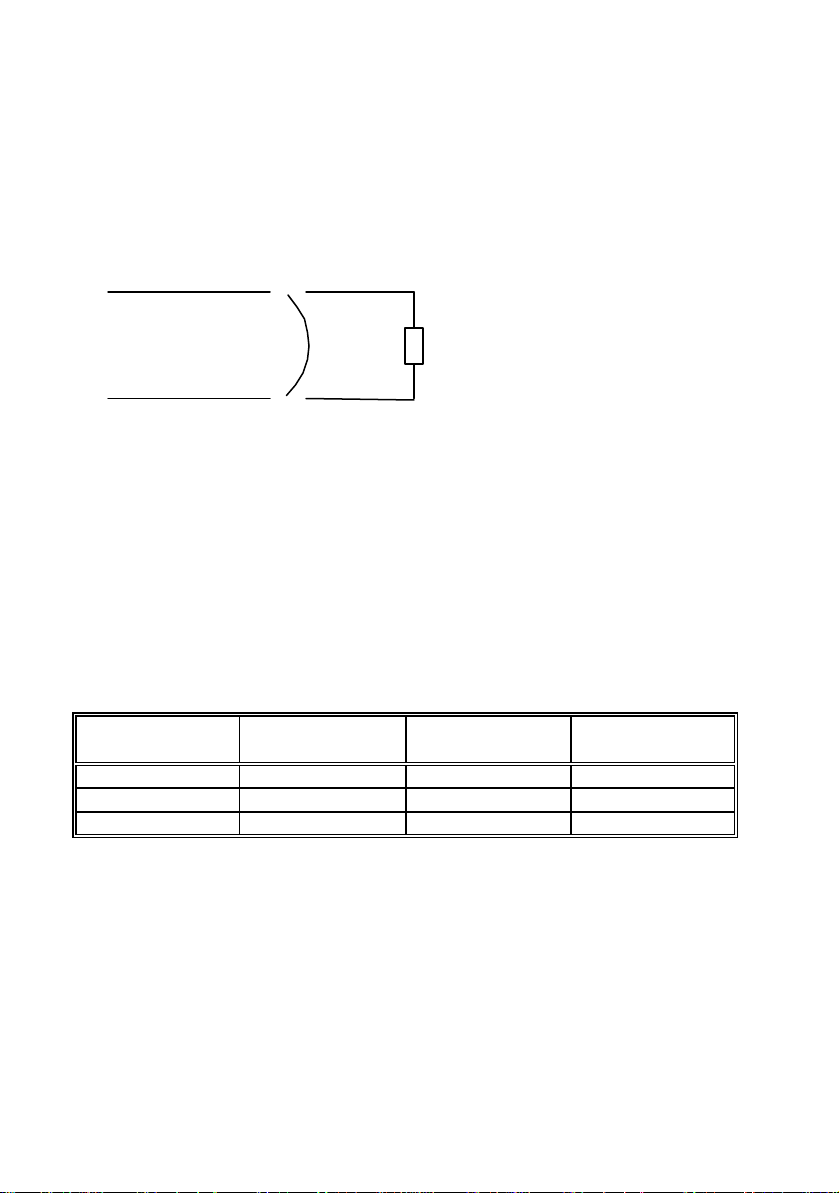
Let’s consider a resistor connected to the output terminals of the power supply
(R resistor).
Limit (programmed) values are:
U
=5V
lim
I
=2A
lim
U
and I
out
are the voltage and current values measured at the output
out
terminals of the power supply.
Depending on the resistor value, the power supply will pass from one mode of
operation to another
R (Ù) U
(V) I
out
(A) Mode of
out
operation
10 5 0.5 CV
5 5 1 CV
1 2 2 CC
In constant voltage mode, programmed voltage value is equal with the voltage
value measured at the output terminals of the power supply. (U
out
= U
lim
).
Using Ohm’s law, depending on the resistor’s value, output current value can
be calculated and it is smaller than current limit value (see first and second
rows of the table).
The power supply will remain in CV operation as long as the limit current
value is greater than output current value.
16
Page 18

When the resistor’s value decreases so the output current value becomes equal
to the current limit value, power supply will go to constant current operation
(see third row of the table) .
If the resistor value is R = 1 Ù, for U
= 5V, using Ohm’s law the output
out
current is 5A. But this value is greater than current limit value, so the power
supply limits the output current to the limit programmed value. That is why in
the third row of the table I
= 2 A. In this case, U
out
is changed, too. Using
out
Ohm’s law again, the output voltage is calculated using output current value
and the resistor value, so it is 2 V.
So the power supply will go to constant current operation when the output
current value becomes equal or greater than the limit value.
When the output current value becomes smaller than the limit value (by
changing resistor’s value), the power supply will go back to constant voltage
operation.
In conclusion:
CV: U
out
= U
lim
and I
out
< I
lim
CC: U
out
< U
lim
and I
out
= I
lim
The following section will explain how to get the power supply in constant
current operation mode and in constant voltage operation mode.
17
Page 19

Constant current operation
In constant current operation, current values in limit mode and normal mode are
the same, but voltage values are not.
To set the power supply in constant current operation, you must follow the
steps described bellow:
1. Select the limit values for voltage and current parameters (U
I
), depending on the application
lim
2. Calculate resistor’s value R
load
.
Using Ohm’s law, calculate the resistor’s value that allows the power supply to
go in constant current mode of operation.
3. Turn on the power supply and set limit mode operation
Press Limit key to set limit mode.
Now the power supply displays limit values for voltage and current. lmt
indicator is displayed, too. (it will be displayed until you go to normal mode).
4. Set voltage and current limit values
Limit values must be chosen so the following conditions are respected:
U
I
lim
> I
lim
· R
,so U
load
lim
lim
< U
< I
out
out
Voltage and current limit values are set using:
Volt / Amp key to select current value,
> < keys to select the digit to adjust (selected digit has cursor underneath it)
knob to set the digit to desired value
5. Set normal mode operation
You can set normal mode operation by pressing Limit key or let the display
time-out (after several seconds with no action, power supply returns to normal
mode operation).
6. Disable the output of the power supply
By pressing On / Off key, the output of the power supply can be disabled.
7. Connect R
R
resistor is connected between (-) and (+) terminals of the power supply.
load
resist or to the output terminals
load
lim
and
18
Page 20

8. Enable the output of the power supply
By pressing On / Off key, you enable the output.
Power supply goes to normal mode operation and CC indicator will be
displayed. In this case constant current operation is active.
If CV indicator will be displayed, you must set a higher value for voltage limit.
Important note!
By turning the knob, voltage and current limit values can be adjusted.
The adjustion of the voltage limit value can be seen only in limit mode.
The adjustion of the current limit value can be seen in both limit mode and
normal mode.
Important note!
Constant current operation can be used depending on the application.
It is very useful to protect the circuitry connected to the power supply from
accidently increases of current value.
19
Page 21

Constant voltage operation
In constant voltage operation, voltage values in limit mode and normal mode
are the same, but current val ues are not
To set the power supply in constant voltage operation, you must follow the
steps described bellow:
1. Select the limit values for voltage and current parameters (U
I
), depending on the application
lim
2. Calculate resistor’s value R
load
.
Using Ohm’s law, calculate the resistor’s value that allows the power supply to
go in constant current mode of operation.
3. Turn on the power supply and set limit mode operation
Press Limit key to set limit mode.
Now the power supply displays limit values for voltage and current. lmt
indicator is displayed, too. (it will be displayed until you go to normal mode).
4. Set voltage and current limit values
Limit values must be chosen so the following conditions are respected:
U
I
lim
< I
lim
· R
load
,so
U
lim
lim
< U
< I
out
out
lim
and
Voltage and current limit values are set using:
Volt / Amp key to select current value,
> < keys to select the digit to adjust (selected digit has cursor underneath it)
knob to set the digit to desired value
5. Set normal mode operation
You can set normal mode operation by pressing Limit key or let the display
time-out (after several seconds with no action, power supply returns to normal
mode operation).
6. Disable the output of the power supply
By pressing On / Off key, the output of the power supply can be disabled.
7. Connect R
R
resistor is connected between (-) and (+) terminals of the power supply.
load
resistor to the output terminals
load
20
Page 22

8. Enable the output of the power supply
By pressing On / Off key, you enable the output.
Power supply goes to normal mode operation and CV indicator will be
displayed. In this case constant voltage operation is active.
If CC indicator will be displayed, you must set a higher value for current limit.
Important note!
By turning the knob, voltage and current limit values can be adjusted.
The adjustion of the current limit value can be seen only in limit mode.
The adjustion of the voltage limit value can be seen in both limit mode and
normal mode.
21
Page 23

On / Off key
On / Of f key is used to enable / disable the output of the power supply from the
front panel. By pressing On / Off key, you alternate these two states: output on
/ output off.
When the output is off, power supply displays:
Output off
The indicators according to power supply’s state will also be displayed (e.g.:
ovp, err indicators).
When output off, output voltage is 0 V. So this command permits a zero output
voltage without switching off the power supply.
When output off, knob is disabled, to prevent the unwanted ch anges in voltage
and current values. The keys from the front panel are not disabled. You can
also go to limit mode and set limit values for voltage and current. In this case
both lmt and off indicators will be displayed.
When output off, by press ing On / Off key,the output is enabled. The power
supply will go to normal mode of operation (voltage and current measured
values are displayed) or to limit mode of operation (voltage and current limit
values are displayed), depending on the state the power supply was before
disabling the output.
The output state of the power supply is one of the parameters stored in nonvolatile memory for each state .
22
Page 24

Remote / Local key
This key has a double function, depending on the state of the power supply
(remote mode or local mode).
Local Mode function
While in local mode of operation, Remote / Local key has a double function,
depending on the state of the power supply.
If the power supply is in calibrating mode, Remote / Local key is used to leave
the calibrating mode and return to normal mode of operation (for more details,
see Calibration Overview section)
When in local mode of operation, by pressing Remote / Local key, RS 232
interface parameters are displayed:
Available settings for RS232 interface:
♦ Baud rate: 1200, 2400, 4800, 9600 (factory setting: 9600)
♦ Parity and data bits: None – 8 data bits (factory setting)
Odd – 7 data bits
Even – 7 data bits
♦ Number of start bits: 1 bit (cannot be changed)
♦ Number of stop bits: 1 bits (cannot be changed)
Set RS – 232 remote interface parameters
1. Select RS – 232 interface
Press Remote / Local key. Following message will be displayed:
RS - 232
Press Remote / Local key again. Baud rate settings will be displayed.
2. Select baud rate
By turning the knob, you will view available baud rate.
When desired baud rate is displayed, press Remote / Local key. Parity settings
will be displayed.
23
Page 25

Select parity
By turning the knob, you will view available parities.
When desired parity is displayed, press Remote / Local key.
These settings are saved in non-volatile memory, so they don’t change when
you turn of the power supply.
If you didn’t change anything of the previous set parameters, the power supply
will display No Change message.
If you did change a single parameter from the previous set parameters, Saved
message will be displayed.
After one of these messages is displayed for several seconds, you return to the
previous state.
Important note!
If you enter in the Remote / Local submenu and no action takes place for
approx. 20 seconds, the power supply will leave this submenu. No Change
message is displayed and the power supply returns to the previous state (the
state before entering this submenu).
Important note!
While in local mode, if by pressing Remote / Local key
message will be displayed, it means that the RS-232 remote interface
parameters cannot be read from the non-volatile memory. The power supply
must be turned off and then turned on.
If this message is displayed again while pres sing Remote / Local key in local
mode, the power supply must be delivered to B&K Precision for service.
Remote interface function
When in remote interface mode of operation, rmt indicator will be displayed.
In this case, all front panel keys are disabled, except Remote / Local key,
which is active. This allows you to put the power supply in local mode of
operation, so all front panel keys become active.
I / O Error
24
Page 26
Errors / Calibrate key
This key has a double function: errors related in normal mode (see this section)
and calibration related in calibration mode (see calibration section).
There are 2 types of errors: user defined errors and errors defined by SCPI 1999
standard.
Every time an error is generated, a beep will be generated by the power supply
and err indicator will be displayed.
Generated errors are saved in an error queue, in FIFO (first in – first out) order.
If more than 20 errors are generated, the last error is overwritten with –350
error (queue overflow error) and no more errors are saved.
While in remote mode (rmt indicator is displayed), errors are erased from the
queue as you read them.
By pressing Errors / Calibrate key, you enter Errors / Calibrate menu. By
turning the knob, following options are displayed:
Errors
Cal String
Exit
Options are selected by pressing Errors / Calibrate key when the desired
option is displayed.
Errors
Errors option allows you to view the generated errors.
If you press Errors / Calibrate key again, by turning the knob you can see
all generated errors. Error’s code will be displayed. When all errors were
viewed, if continue to turn the knob, they will be displayed again.
After you viewed all errors, you press Errors / Calibrate key again. The
power supply will erase all the errors from the error queue and Errors
Erased message will be displayed.
25
Page 27

After several seconds the power supply will go back to normal mode. The
err indicator will not be displayed anymore.
If there are no errors in the queue and you select Errors option in order to
view the errors, the power supply will display:
No Errors
And then it will return to normal mode.
There are 3 ways of erasing the error queue:
♦ By turning off and then turning on the power supply
♦ By pressing Errors / Calibrate key after errors are displayed, in local
mode
♦ By reading errors, in remote operation.
Important note!
If you let the display time out, the power supply will go back to normal
mode, without erasing the error queue.
Cal String
The power supply allows you to store a calibration message. It may contain
last calibration date, the date when the next calibration must be done or the
name and the phone number of the person to contact for a new calibration.
This message can have up to 40 characters. It can be set only remote
interface and it is saved in non-volatile memory.
When delivered, the power supply has the following calibration string set:
“CALIBRATION DATE: MMM/DD/YYYY” (for example:
CALIBRATION DATE: Feb/11/2005)
Cal String option allows you to view the calibration string.
If you press Errors / Calibrate key when Cal String option is displayed,
the calibration message will be displayed. To scroll through the calibration
message, you must press < key. To increase the scrolling speed, you must
press > key. To decrease scrolling speed, you must press < key.
26
Page 28

Exit
Exit option allows you to leave this menu, without changing anything.
Exiting message will be displayed and the power supply returns to the
previous state (the state before entering this menu).
Important note!
If you enter in the Errors / Calibrate menu and no action takes place for
approx. 20 seconds, the power supply leaves this menu. Exiting message is
displayed and the power supply returns to the previous state (the state before
entering Errors / Calibrate menu).
27
Page 29

Calibration overview
Calibration is a procedure that ensures that the power supply will work
properly, with parameters specified within Technical Specification section.
Before initiating the calibration procedure, the following conditions must be
assured:
§
disconnect any loads connected to the power supply and turn it on
§
§
let the power supply turned on for 1 hour, with no loads connected before
§
you start the calibration procedure
§
calibration ambient temperature must be 25 0C
§
§
ambient relative humidity must be less then 80%.
§
Recommended calibration interval is 1 year.
Important note!
In order to perform the calibration procedure, a digital multimeter is needed. It
must have the following characteristics:
Voltage resolution: 0.1 mV
Current resolution: 0.01 mA
Acurracy: 0.01 %
Calibration security code
To prevent accidental or unauthorized calibration procedures, the power supply
has a calibration security code. This security code is optional, so you may have
it or not. The power supply will work properly in both cases.
Security code may contain numbers (0..9), small letters (a..z) and spaces (“ “).
Any of these characters may be used as the first character in security code.
Security code may contain up to 11 characters. But it is not necessary for you to
use all 11 char acters for the security code.
The security code is saved in non-volatile memory and it doesn’t change when
you turn on or turn off the power supply.
When delivered, power supply has the following security code: 0000
In order to initiate the calibration procedure, first you must unsecure the power
supply (if a security code is set).
28
Page 30

Unsecure procedure for calibration
To unsecure the power supply, the next steps bust be followed:
1. Turn on the power supply in calibrating mode
To enter calibrating mode, you must turn on the power supply while pressing
Errors / Calibrate key. You release the key after the long beep. After that, the
power supply will display:
Calibrating Mode
Secured
if the power supply is secured (if the power supply has a security code set). If
this message is displayed, go to step 2.
or :
Calibrating Mode
Unsecured
if the power supply is not secured (if the power supply has been turned off after
the unsecure procedure).
If the power supply is already unsecured, you can proceed with calibration (see
Calibration procedure section)
2. Enter security code
Press OVP / Secure key. The power supply will display:
Security code:
_ _ _ _ _ _ _ _ _ _ _
Here you must enter the security code, using > < keys and knob. The selected
digit has the cursor underneath it. If you set the digit to the desired value, you
must press > key and go to the next digit, if you want.
After you entered the security code, press OVP / Secure key and if the security
code is correct, the power supply will display:
Calibrating Mode
Unsecured
29
Page 31

From this moment you can proceed with calibration (see Calibration
p rocedure section) or you can go back to normal mode operation.
From now on, the power supply remains unsecured until you set a new secure
code.
If the security code you entered is not correct, power supply will display:
Security code:
invalid
for 1 second. 703 error (Invalid secure code) and a short beep will be
generated. You can see the error in normal mode operation (by pressing Local
key).
After that power supply will display again:
Security code:
_ _ _ _ _ _ _ _ _ _ _
and you must enter security code again , using < > keys and knob. If you don’t
remember the correct security code, you may follow the hardware unsecure
procedure (see Hardware unsecure procedure ).
Important Note!
While in calibrating mode, before you unsecure the power supply, only Local,
< > and Secure keys are active (all the rest are locked). The knob is also active.
Local key can be used at any moment of unsecure procedure to leave
calibrating mode and go back to normal mode operation. Secure key is used in
unsecure procedure of the power supply (allows you to enter and validate the
secure code).
While in calibrating mode, after you unsecure the power supply, only Local,
Secure, < > and Calibrate keys are active. The knob is also active.
Local key is used to leave calibrating mode and go back to normal mode
operation.
Secure key is used to set a new security code (you may introduce a new
security code and secure again the power supply).
Calibrate key is used to proceed with calibration.
Attention!
Local key is active all the time while in calibrating mode and by pressing it the
power supply returns to normal mode. Leaving the unsecure procedure does not
30
Page 32

change anything concerning the secure state of the power supply (secured or
unsecured).
After you changed the security code or unsecured the power supply, you can go
back to normal mode by pressing Local key. (You can come back to
calibrating mode only by turning off the power supply and starting it in
calibrating mode).
But once you started the calibration procedure, it is recommended to finish it
and to go back to normal mode by turning off and on the power supply.
31
Page 33

Hardware unsecure procedure for calibration
This procedure may be used to unsecure the power supply if you forgot the
security code.
To unsecure the power supply without using the security code, follow the next
steps:
1. Turn off the power supply. Disconnect the power cord and all loads
connected to the power supply.
2. Remove power supply’s cover. Set J6 jumper for hardware unsecuring
mode.
J5 J6
J5 J6
Normal
unsecuring
3. Connect the power cord to the power supply. Turn on th e power supply in
calibrating mode.
4. Unsecure the power supply.
To unsecure the power supply you must press Secure key. Power supply will
display:
Calibrating Mode
Secured
Press again Secure key the power supply will display:
Security code:
_ _ _ _ _ _ _ _ _ _
Here any security code may be introduced, since it is not verified by the power
supply.
Press again Secure key and you will unsecure the power supply. It will display:
Calibrating Mode
Unsecured
Hardware
unsecuring
32
Page 34

The power supply remains unsecured until you enter a new security code.
Important note!
Even if you are in calibrating mode, you cannot set a security code as long as
the J6 jumper is in hardware unsecuring position.
5. Set J6 jumper for normal unsecuring mode.
Important note!
If you turn on the power supply in either normal mode or calibrating mode and
J6 jumper is in hardware unsecuring position, error 701 (Calibration security
disabled by jumper) will be generated.
6. Turn off the power supply and reassemble it.
33
Page 35

Calibration procedure
Before initiating the calibration procedure, the following conditions must be
assured:
§
disconnect any loads connected to the power supply and turn it on
§
§
let the power supply turned on for 1 hour, with no loads connected before
§
you start the calibration procedure
§
calibration ambient temperature must be 25 0C
§
§
ambient relative humidity must be less then 80%.
§
On calibration procedure there are three parameters that must be calibrated:
voltage, OVP and current.
You can leave the calibration procedure at any time by turning off the power
supply or by pressing Local key.
But once you started the calibration procedure, it is recommended to finish it
and to go back to normal mode by turning off and then turning on the power
supply.
In order to be sure that the power supply will work properly in normal mode
after you leave the calibration procedure, you must turn off the power supply.
Recommended calibration interval is 1 year.
Before calibrating the power supply you must unsecure it, if secured (see
Calibration Overview section).
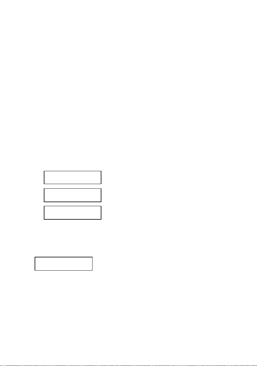
After you unsecured the power supply and you pressed Calibrate key, you go
to Calibrate menu. By turning the knob next options are available:
1. Volt Zero Scale
2. Volt Full Gain
3. OVP
4. Curr Zero Scale
5. Curr Full Gain
Options are selected by pressing Calibrate key.
Important note!
In order to perform a correct calibration the calibration procedures from the
Calibrate menu must be followed in the order they are displayed by the power
supply.
34
Page 36

Voltage Calibration Procedure
After you unsecured the power supply and you pressed Calibrate key, you
entered calibrate mode.
Volt Zero Scale Calibration
1. Select Volt Zero Scale calibration procedure
In order to start voltage calibration procedure, you must select Volt Zero Scale
option.
The power supply will display:
You select this option by pressing Calibrate key.
The power supply will display:
2. Initiate DAC calibration procedure
Connect a digital voltmeter to the output terminals of the power supply. After
that, you must adjust DAC value displayed by the power supply until the
voltmeter indicates the closest possible to 0.000 V value.
For this, you use > < keys and the knob.
It is not necessary to disconnect the digital voltmeter, since you will need it
later on calibration procedure!
3. Initiate ADC calibration procedure
Press Calibrate key. This will initiate ADC calibration procedure. The power
supply will display:
After ADC calibration, power supply will return to Calibrate menu Volt Full
Gain calibration procedure.
Calibrating Mode
Volt Zero Scale
Volt Zero Scale
DAC:1999
Volt Zero Scale
ADC Calibrating
35
Page 37

Volt Full Gain Calibration
1. Select Volt Full Gain calibration proce dure
In order to finish voltage calibration procedure, you must select Volt Full Gain
option.
The power supply will display:
You select this option by pressing Calibrate key.
The power supply will display:
2. Initiate DAC calibration procedure
Connect a digital voltmeter to the output terminals of the power supply. After
that, you must adjust DAC value displayed by the power supply until the
voltmeter indicates the correct voltage value, depending on the model of the
power supply (see the tabl e bellow).
For this, you use > < keys and the knob
3. Initiate ADC calibration procedure
Press Calibrate key. This will initiate ADC calibration procedure. The power
supply will display:
After ADC calibration, power supply will return to Calibrate menu, OVP
calibration procedure.
Calibrating Mode
Volt Full Gain
Volt Full Gain
DAC:31470
Power supply model Voltage value for
Volt Full Gain calibration
9120 16.3840 V
9121 16.3840 V
9122 32.7680 V
Volt Full Gain
ADC Calibrating
36
Page 38

OVP Calibration
While performing this calibration procedure, the power supply must have no
loads connected to the output terminals.
1. Select OVP calibration procedure
In order to initiate OVP calibration procedure, you must select OVP option.
The power supply will display:
You select this option by pressing Calibrate key.
The power supply will displ ay:
Important note!
This calibration procedure will take several minutes.
After OVP calibration, power supply will return to Calibrate menu, Current
calibration procedure.
Calibrating Mode
OVP
Calibrating OVP
Please wait…
37
Page 39

Current Calibration Procedure
Current calibration procedure must be permormed after Voltage calibration
procedure.
Current Zero Scale Calibration
While performing this calibration procedure, the power supply must have no
loads connected to the output terminals.
1. Select Curr Zero Scale calibration procedure
In order to start current calibration procedure, you must select Curr Zero Scale
option.
The power supply will display:
2. Initiate DAC calibration procedure
You select this option by pressing Calibrate key. So Current Zero Scale
calibration procedure will be initiated.
The power supply will display:
After a while, the power supply will display:
Important note!
This calibration procedure will take several minutes.
Calibrating Mode
Curr Zero Scale
Curr Zero Scale
ADC:Calibrating
Curr Zero Scale
DAC:Calibrating
After Current Zero Scale calibration procedure, power supply will return to
Calibrate menu, Curr Full Gain calibration procedure.
38
Page 40

Curr Full Gain Calibration
1. Select Curr Full Gain calibration procedure
In order to finish current calibration procedure, you must select Curr Full
Gain option.
The power supply will displ ay:
You select this option by pressing Calibrate key.
The power supply will display:
2. Initiate DAC calibration procedure
In order to initiate Curr Full Gain calibration procedure, you must connect a
digital ammeter to the output terminals of the power supply.
If don’t connect a digital ammeter within 30 seconds, the power supply will
display:
and it will return to Calibrate menu.
After you connected the digital ammeter, you must adjust DAC value displayed
by the power supply until the ammeter indicates indicates the correct current
value, depending on the model of the power supply (see the table bellow).
For this, you use > < keys and the knob
3. Initiate ADC calibration procedure
Press Calibrate key. This will initiate ADC calibration procedure. The power
supply will display:
Calibrating Mode
Curr Full Gain
Curr Full Gain
Connect Ammeter
Calibrating Mode
CC Not Set
Power supply model Current value for
Curr Full Gain calibration
9120 2.62144 A
9121 2.62144 A
9122 1.31072 A
39
Page 41

Curr Full Gain
ADC Calibrating
After ADC calibration, power supply will return to Calibrate menu.
In this moment, the calibration procedure is finished. By presing Local key, the
power supply will return to local mode.
Important note!
In order to be sure that the power supply will work properly in normal mode
after you leave the calibration procedure, you must turn off the power supply.
40
Page 42

OVP / Secure key
This key has a double function: OVP settings in normal mode operation and
secure key in calibration mode operation (for the latter see Calibration
section).
In this section OVP functions will be described.
OVP circuit prevents the output voltage from rising above a programmed
voltage value. So the load connected to the output terminals is protected to
overvoltage situations.
Overvoltage protection circuit is activated when output voltage value becomes
equal or greater than the programmed trip level for overvoltage protection
circuit.
OVP menu overview
By pressing OVP / Secure key, you enter OVP menu.
Here, programmed OVP trip level will be displayed.
When you turn on the power supply, OVP trip level is OVP trip level value
saved at power_up state (state 0). This value can be changed by the user (and
saved in power_up state if wanted).
Here you can set desired OVP trip level, by using > < keys to select the digit
you want to adjust (sel ected digit has the cursor underneath) and knob to set the
digit to desired value.
The programming range for OVP trip level depends on the model of the power
supply (see the table bellow):
Power supply
model
9120 1 V 33 V
9121 1 V 22 V
9122 1 V 63 V
The OVP trip level you set is programmed by pressing OVP / Secure key.
After that, you enter the OVP menu.
By turning the knob, following options are displayed:
OVP min value OVP max value
41
Page 43

OVP On
OVP Clear
OVP Off
Options are selected by pressing OVP / Secure key when the desired option is
displayed.
OVP On
OVP On option enables overvoltage protection circuit. OVP trip level is the
level value you programmed on Level option (after you first pressed OVP /
Secure key).
If you want to keep the previously programmed trip level, you simply press
OVP / Secure key, without changing anything.
If you enable the overvoltage protection circuit, when you return to normal
mode, ovp indicator will be displayed.
OVP Off
OVP Off option makes OVP trip level equal to maximum availabale OVP
value , no matter what what value is set in OVP menu (but the value from
OVP menu does not change).
For maximum available OVP value see the table above.
If you select OVP Off option, when you return to normal mode, ovp
indicator will not be displayed anymore.
Important note!
When OVP On option is selected, OVP trip level is equal to the
programmed level, shown in OVP menu.
When OVP Off option is selected, OVP trip level is equal to the maximum
available value for this parameter, depending on the model of the power
supply (see the table above). In this case, the programmed OVP trip level,
shown in OVP menu does not change!
42
Page 44

Output Off
OVP Clear
OVP Clear option is used to clear to OVP condition (for more details about
how you get back to normal mode after OVP level was tripped, see next
section).
After you select the desired option, a message will be displayed.
If you didn’t change anything of the previous set parameters, the power
supply will display No Change message.
If you did change a single parameter from the previous set parameters Done
message will be displayed.
After one of these messages is displayed for several seconds, you return to
normal mode.
Important note!
If you enter in the OVP menu and no action takes place for approx. 20 seconds,
the power supp ly will leave the OVP menu. No Change message is displayed
and the power supply returns to the previous state (the state before entering
OVP menu).
If the output voltage value becomes equal or greater than OVP programmed
level and the overvoltage protection circuit is enabled, the power supply will
display:
Over Voltage
And the output voltage value will be 0 V (output is disabled).
There are three ways of clearing the OVP condition:
Ø By increasing OVP trip level and clearing the OVP condition
Ø By decreasing the output voltage and clearing the OVP condition
Ø By disabling OVP circuit and by clearing the OVP condition
Important note!
When you turn on the power supply, the overvoltage protection circuit is
enabled and the OVP trip level is equal to the one saved in power_up state
(factory setting: maximum available value ).
43
Page 45

Programming overvoltage protection circuit in front panel mode
If you want to program an OVP trip level and to enable the overvoltage
protection circuit using front panel keys, follow the next st eps:
1. Turn on the power supply
When you turn on the power supply, the overvoltage protection circuit is
enabled and OVP trip level is set to maximum available value for OVP
parameter, depending on the model of the power supply (see table in the
prevous sec tion).
2. Enter the OVP menu and set OVP trip level
By pressing OVP / Secure key, you enter the OVP menu. The power supply
will display the programmed OVP trip level.
For changing this value, you can use > < to select the digit you want to adjust
(selected digit has the cursor underneath) and then turn the knob to set the
desired value.
After you set the desired value for OVP trip level, you press OVP / Secure key.
Important note!
You cannot set an OVP trip level lower than 1 Volt.
The maximum OVP trip le vel value depends on the model of the power supply
(see table in the previous section )
3. Enable the OVP circuit
After you set the desired OVP trip level and you pressed OVP / Secure key,
OVP On, OVP Off and OVP Clear options are available.
To enable the OVP circuit, you select OVP On option by turning the knob
OVP On
4. Exit the OVP submenu
To exit the OVP submenu and to validate all the settings you have done, then
you press OVP / Secure key.
After that, Changed message will be displayed and the power supply return to
previous state (the state before you entered the OVP submenu), in normal mode
operation.
44
Page 46

ovp indicator will be displayed. If you didn’t change anything, the power
supply will display No Change message.
45
Page 47

Clearing the overvoltage condition
Output Off
There are three ways of clearing the OVP condition:
Ø By increasing OVP trip level and clearing the OVP condition
Ø By decreasing the output voltage and clearing the OVP condition
Ø By disabling OVP circuit and by clearing the OVP condition
Attention!
The latter solution disables the OVP circuit, but the first and the second don’t!
In this section we will describe the steps you must follow to clear the OVP
condition in all three cases.
If the output voltage value becomes equal or greater than OVP programmed
level and the overvoltage protection circuit is enabled, the power supply will
display:
Over Voltage
And the output voltage value will be 0 V (output is disabled).
46
Page 48

Clearing OVP condition
Clearing the OVP condit ion by increasing OVP trip level
1. Enter the OVP menu
By pressing OVP / Secure key, you enter the OVP menu.
2. Adjust OVP trip level
When you enter OVP menu, OVP trip level is displayed.
Here, you set OVP trip level to a level higher than the programmed voltage
value (U
lim
).
3. Clear OVP condition
After you set the OVP trip level, you press OVP / Secure key.
Here, OVP On, OVP Off, OVP Clear options are available. Select OVP
Clear option by turning the knob.
OVP Clear
After that, press OVP / Secure key. The power supply will display:
Clear OVP:Done
and after several seconds it will return to normal mode. ovp indicator will be
displayed (the OVP circuit is still enabled).
Important note!
If you enter in the OVP menu and no action takes place for approx. 20 seconds,
the power supply will leave the OVP menu. No Change message is displayed
and the power supply returns to the previous state (the state before entering
OVP menu).
47
Page 49

Clearing the OVP condition by decreasing the output voltage
1. Decrease the output voltage level bellow OVP trip level
Press Limit key and enter limit mode. Limit values of voltage and current will
be displayed. ovp and lmt indicators will also be displayed.
Adjust for output voltage limit to a lower value than the OVP trip level.
Press Limit key to exit limit mode.
2. Enter OVP menu and clear OVP condition
Here you check that the OVP trip level is greater than the output voltage limit
you set. If it isn’t, go to step 1.
Don’t adjust OVP trip level!
Clear OVP condition by turning the knob and selecting OVP Clear option:
OVP Clear
After that, press OVP / Secure key. The power supply will display:
Clear OVP:Done
and after several seconds it will return to normal mode. ovp indicator will be
displayed (the OVP circuit is still enabled).
Important note!
If you enter in the OVP menu and no action takes place for approx. 20 seconds,
the power supply will leave the OVP menu. No Change message is displayed
and the power supply returns to the previous state (the state before entering
OVP menu).
48
Page 50

Clearing the OVP condition by disabling OVP circuit
Output Off
1. Disable OVP circuit
By pressing OVP / Secure key, you enter OVP menu.
Here you disable OVP circuit by turning the knob and selecting OVP Off
option.
OVP Off
It doesn’t matter if you change or not OVP trip level as long as you disable the
OVP circuit. But you must be careful to set it to the right value before you
enable OVP circuit next time.
After you selected OVP Off option and you pressed OVP / Secure key, the
power supply will display
Over Voltage
because you didn’t clear the OVP condition yet
2. Enter OVP menu and clear OVP condition
You enter OVP menu again by pressing OVP / Secure key. Now you clear
OVP condition by turning the knob and selecting OVP Clear option:
OVP Clear
After that, press OVP / Secure key. The power supply will di splay:
Clear OVP:Done
and after several seconds it will return to normal mode. ovp indicator will be
displayed (the OVP circuit is still enabled).
Important note!
If you enter in the OVP menu and no action takes place for approx. 23 seconds,
the power supply will le ave the OVP menu. No Change message is displayed
and the power supply returns to the previous state (the state before entering
OVP menu).
49
Page 51

Rear panel description
+s
-s
+
-
On the rear panel of the power supply there are:
§
RS-232 interface connector
§
§
AC inlet
§
§
Power-line fuse -holder assembly
§
§
Rear output terminals.
§
The sensing terminals (+s and -s) are connected to the outp ut terminals of the
power supply by jumpers.
For the power supply to work properly, the jumpers must be kept in that
position.
50
Page 52

Remote interface
RS – 232 interface is used for remote communication.
For this, you must connect your power supply to a computer terminal (see
Technical Specification section, Interface Cable paragraph).
For remote control of the power supply, SCPI (Standard Commands for
Programmable Instruments) commands are used.
In this section SCPI commands will be described to you.
Here are some conventions used in SCPI standard:
♦ A command consists of a command keyword (command name) and a
parameter (it may be optional or not)
♦ Lower case and upper case letters are considered equivalent
♦ Letter case is used to differentiate between the accepted short form (the
uppercase characters) and the long form (the whole keyword)
♦ Square brackets ( [ ] ) are used to enclose:
♦ a keyword that is optional when programming the command
♦ one or more parameters that are optional when controlling the
instruments.
If no parameter is specified, default parameter is considered.
The braces are not sent with the command string.
♦ Braces or curly brackets ( {} ) are used to enclose one or more parameters
that may be included zero or more times.
The braces are not sent with the command string.
♦ The angle brackets (<>) are used to enclose the type name.
A value of the specified type must be added to the command.
The angle brackets are not sent with the command string.
♦ The vertical bar ( | ) can be read as “or” and it is used to separate
alternative parameter options.
Only one parameter can be sent with the command.
♦ The query form of a command is generated by appending a question mark
to the last keyword. Not all commands have a query form and some
commands exist only in query form.
51
Page 53

SCPI Command Terminators
A command string sent to the power supply must terminate with a new line
character (ASCII decimal code of 10) or a a carriage return character (ASCII
decimal code of 13 )
Important note!
The power supply will go to remote mode of operation (it can accept
commands over RS232 interface) if SYSTem:REMote command is sent.
If other remote interface commands are sent before sending SYSTem:REMote
command, the power supply will respond with Power supply in local mode
message.
52
Page 54

SCPI commands
DISPLAY Subsystem
:DISPlay
[:WINDow][:STATe ] {OFF|ON}
[:WINDow][:STATe ]?
[:WINDow]:TEXT[:Data] <quoted string>
[:WINDow]:TEXT[:DATA]?
[:WINDow]:TEXT:CLEar
MEASure Subsystem
:MEASure
:CURRent[:DC]?
[:VOLTage][:DC]?
OUTPut Subsystem
:OUTPut
[:STATe] {OFF|ON}
[:STATe]?
SOURCE Subsystem
[:SOURce]
:CURRent[:LEVel][:IMMediate][:AMPLitude] {<current>|MIN|MAX|UP|DOWN}
:CURRent[:LEVel][:IMMediate][:AMPLitude]? [MIN|MAX]
:CURRent[:LEVel][:IMMediate]:STEP[:INCrement] {<numeric value>|DEFault}
:CURRent[:LEVel][:IMMediate]:STEP[:INCrement]? [DEFault]
:CURRent[:LEVel][:IMMediate]:TRIGgered[:AMPLitude] {<current>|MIN|MAX}
:CURRent[:LEVel][:IMMediate]:TRIGgered[:AMPLitude]? [MIN|MAX]
:VOLTage[:LEVel][:IMMediate][:AMPLitude] {<current>|MIN|MAX|UP|DOWN}
:VOLTage[:LEVel][:IMMediate][:AMPLitude]? [MIN|MAX]
:VOLTage[:LEVel][:IMMediate]:STEP[:INCrement] {<numeric value>|DEFault}
:VOLTage[:LEVel][:IMMediate]:STEP[:INCrement]? [DEFault]
:VOLTage[:LEVel][:IMMediate]:TRIGgered[:AMPLitude] {<voltage>|MIN|MAX}
:VOLTage[:LEVel][:IMMediate]:TRIGgered[:AMPLitude]? [MIN|MAX]
:VOLTage:PROTection[:LEVel] {<voltage>|MIN|MAX}
:VOLTage:PROTection:STATe {0|1|OFF|ON}
:VOLTage:PROTection:STATe?
:VOLTage:PROTection:TRIPped?
:VOLTage:PROTection:CLEar
SYSTem Subsystem
:SYStem
:BEEPer[:IMMediate]
:ERRor?
53
Page 55

:VERSion?
TRIGger Subsystem
INITiate[:IMMediate]
TRIGger[:SEQuence]:DELay {<seconds>|MIN|MAX}
TRIGger[:SEQuence]:DELay? [MIN|MAX]
TRIGger[:SEQuence]:SOURce {BUS|IMM}
TRIGger[:SEQuence]:SOURce?
*TRG
Non-SCPI commands
SET {<voltage>|DEF|MIN|MAX}[,<current>|DEF|MIN|MAX]
SET?
CALibration:MESSAGE <quoted string>
CALibration:MESSAGE?
SYSTem:REMote
IEEE 488.2 commands
*CLS
*ESE <enable value>
*ESE?
*ESR?
*IDN?
*OPC
*OPC?
*RST
*SAV {0 | 1 | 2 | … | 99}
*RCL {0 | 1 | 2 | … | 99}
*SRE <enable value>
*SRE?
*STB?
*TRG
54
Page 56

SCPI commands overview
System – Related Commands
DISPlay Subsystem
This subsystem controls the presentation of textual information and
measurement data.
:DISPlay[:WINDow][:STATe] {0|1|OFF|ON}
This command turns power supply’s display off and on. When the display is
off, only annunciators are displayed.
You can replace off|on parameters with 0|1 numeric values.
:DISPlay[:WINDow][:STATe]?
This command queries front panel display status. It returns only numeric
values: 0 (off) or 1 (on).
:DISPlay[:WINDow]:TEXT[:Data] <quoted string>
This command displays a message on the front panel. The power supply will
display up to 16 characters and all the rest will be truncated. The string will be
sent between simple or double quotes.
:DISPlay[:WINDow]:TEXT[:DATA]?
This command queries the last sent message. It returns a quoted string.
DISPlay[:WINDow]:TEXT:CLEar
This command clears the message displayed on the front pannel. Power supply
will return to the previous state.
55
Page 57

OUTPut Subsystem
This subsystem controls the output of the power supply.
:OUTPut[:STATe] {0|1|OFF|ON}
This command enables and disables the output of the power supply. You can
replace off | on parameters with 0 | 1 numeric values.
When output is enabled, the power supply will display voltage and current
value measured on the output terminals of the power supply.
When output is disabled, the power supply will display Output Off message
and the annunciators according to power supply’s state.
When output is disabled, output voltage is 0 V and the current is 0.002 A.
After power on reset, output will be disabled.
OUTPut[:STATe]?
This command queries the output state of the power supply. It returns only
numeric values: 0 (for off state) or 1 (for on state)
SYSTem Subsystem
This subsystem contains functions that are not directly related to power supply
performance.
:SYStem:BEEPer[:IMMediate]
This command determines the power supply to generate a beeper right after she
received this command.
:SYSTem:ERRor?
This command queries the power supply’s error queue. Errors are retrieved in a
firs-in-first-out order, so the first generated error is the first read error. When all
the errors were read, err annunciator will not be displayed anymore and error
queue is empty.
The error queue can store up to 20 errors. If more errors will be generated, on
the last position will be written – 350 error (queue overflow) and no more
errors will be stored until the queue is cleared.
:SYSTem :VERSion?
This command queries the SCPI version number for which the instrument
complies. The response is a strin g in the form YYYY.V, where YYYY represents
the year version and V represents the approved revision number for that year
(for example, 1990.0).
56
Page 58

Output Setting Commands
SOURce Subsystem
According to SCPI standard, SOURce node is optional, so the devices which
are primarily sources accept shorter commands.
This subsystem contains commands that program power supply parameters or
commands that query programmed power supply parameters (for example:
programmed values for current and voltage, programmed values for step
current and step voltage, lowest or highest value possible to program for current
and voltage )
:CURRent[:LEVel][:IMMediate][:AMPLitude] {<current>|MIN|MAX|UP|DOWN}
This command allows you to set the current value to the output of the power
supply.
Instead of a numeric value, you can use “MINimum” os “MAXimum”, “Up” or
“DOWN” parameters.
MIN allows you to set the lowest current value, which is 0 A.
MAX allows you to set the highest possible current value for model you have.
With UP or DOWN parameters, this command allows you to increase /
decrease the output value of the current with a preset value (the step you set
with :CURRent:STEP {< numeric value>|DEFault} command, or the default
step of the power supply). When you exceed the minimum or the maximum
possible value by increasing / decreasing the output value, error – 222 (Data out
of range) error will be generated.
:CURRent[:LEVel][:IMMediate][:AMPLitude]? [MIN|MAX]
This command queries the programmed current level. When using MIN or
MAX parameters, the power supply returns the lowest and the highest value
that are possible to program for current.
:CURRent[:LEVel][:IMMediate]:STEP[:INCrement]{<numeric value>|DEFault}
This command allows you to set the current step for CURR UP or CURR
DOWN command. The minimum value for step is 1 mA.
:CURRent[:LEVel][:IMMediate]:STEP[:INCrement]? [DEFault]
This command queries the programmed step value (if no parameter specified),
or the default step value (if DEFault parameter is specified within the
command). The returned value is specified in Amps.
Example: Here is an example of how you program current step value and
how you increase / decrease current output value using step.
57
Page 59

CURR:STEP 0.2 ;program current step value
CURR UP ;increase output current
CURR:STEP 0.5 ;program current step value
CURR DOWN ;decrease output current
Note: If no step value was programmed before CURR UP or CURR
DOWN commands, default step value (0.001 A) will be used.
CURRent[:LEVel][:IMMediate]:TRIGgered[:AMPLitude] {<current>|MIN|MAX}
This command allows you to program the current trigger value, which is
transfered to the output terminals when a trigger signal occurs.
By programming this value, you don’t change the current programmed value.
Instead of a numeric value, you can use “MINimum” or “MAXimum
parameters.
MIN allows you to set the lowest current value, which is 0 V.
MAX allows you to set the highest possible current value for model you have.
:CURRent[:LEVel][:IMMediate]:TRIGgered[:AMPLitude]? [MIN|MAX]
This command queries the programmed current trigger level. When using MIN
or MAX parameters, the power supply returns the lowest or the highest value
allowed for current trigger parameter.
:VOLTage[:LEVel][:IMMediate][:AMPLitude] {<voltage>|MIN|MAX|UP|DOWN}
This command allows you to set the voltage value to the output of the power
supply.
Instead of a numeric value, you can use “MINimum” or “MAXimum”, “Up” or
“DOWN” parameters.
MIN allows you to set the lowest voltage value, which is 0 V.
MAX allows you to set the highest possible current value for model you have.
With UP or DOWN parameters, this command allows you to increase /
decrease the output value of the voltage with a preset value (the step you set
with :VOLTage:STEP {<numeric value>|DEFault} command, or the default
step of the power supply). When you exceed the minimum or the maximum
possible value by increasing / decreasing the output value, error – 222 (Data out
of range) error will be generated.
:VOLTage[:LEVel][:IMMediate][:AMPLitude]? [MIN|MAX]
This command queries the programmed voltage level. When using MIN or
MAX parameters, the power supply returns the lowest or the highest value that
is possible to program for voltage parameter.
:VOLTage[:LEVel][:IMMediate]:STEP[:INCrement] {<numeric value>|DEFault}
58
Page 60

This command allows you to set the voltage step for VOLT UP or VOLT
DOWN command. The minimum value for step is 10 mV.
:VOLTage[:LEVel][:IMMediate]:STEP[:INCrement]? [DEFault]
This command queries the programmed step value (if no parameter specified),
or the default step value (if DEFault parameter is specified within the
command) for voltage. The returned value is specified in Volt.
Example: Here is an example of how you program voltage step value and
how you increase / decrease voltage output value using step.
VOLT:STEP 0.2 ;program voltage step value
VOLT UP ;increase output voltage
VOLT:STEP 0.5 ;program voltage step value
VOLT DOWN ;decrease output voltage
Note: If no step value was programmed before VOLT UP or VOLT
DOWN commands, default step value (0.011 V) will be used.
:VOLTage[:LEVel][:IMMediate]:TRIGgered[:AMPLitude] <current>|MIN|MAX}
This command allows you to program the voltage trigger value, which is
transfered to the output terminals when a trigger signal occurs.
By programming this value, you don’t change the voltage programmed value.
Instead of a numeric value, you can use “MINimum” or “MAXimum
parameters.
MIN allows you to set the lowest voltage value, which is 0 V.
MAX allows you to set the highest possible voltage value for model you have.
:VOLTage[:LEVel][:IMMediate]:TRIGgered[:AMPLitude]? [MIN|MAX]
This command queries the programmed voltage trigger level. When using MIN
or MAX parameters, the power supply returns the lowest or the highest value
allowed for vol tage trigger parameter.
:VOLTage:PROTection[:LEVel] {<voltage>|MIN|MAX}
This command allows you to set the voltage level at which the the overvoltage
protection circuit will be activated. If the output voltage will get equal or
greater than the programmed OVP level, then the power supply will have
output voltage value 0 V (output is disabled).
:VOLTage:PROTection:STATe {0|1|OFF|ON}
This command allows you to disable / enable the overvoltage protection circuit.
After power on reset, the overvoltage protection circuit is enabled and the
programmed OVP value is 33 Volt.
59
Page 61

:VOLTage:PROTection:STATe?
This command queries the overvoltage protection circuit state. The returned
parameter is always a numeric parameter: 0 (for OFF state) or 1 (for ON state).
:VOLTage:PROTection:TRIPped?
This command queries if the protection circuit is tripped or not. The returned
parameter is always a numeric parameter:. 0 for OVP circuit not tripped or 1 for
OVP circuit tripped.
:VOLTage:PROTection:CLEar
This command allows you to clear the overvoltage protection circuit. This
command does not affect the programmed voltage trip level.
After this command the power supply returns to the previous state (output
voltage will have the same value as before OVP was enabled). In this case,
before you clear the protection circuit, you must lower the output voltage below
OVP trip level or increase the OVP trip level above the output voltage value.
Here are some examples of how you work with overvoltage protection circuit
using remote interface commands:
Example 1: Here is an example of how you program the overvoltage
protection circuit using remote interface commands:
VOLT:PROT 5 ;set OVP trip level at 5V
VOLT:PROT? ;responds with programmed OVP trip level (5V)
VOLT:PROT:STAT ON ;enable OVP circuit
VOLT:PROT:STAT? ;responds with OVP circuit state (1 or 0n)
VOLT:PROT:TRIP? ;responds if OVP circuit is enabled
;(0 if output voltage lower than OVP trip
;level and 1 otherwise)
Attention: OVP circuit is enabled if output voltage becomes equal or
greater than the programmed trip level for OVP circuit.
It is not necessary to check every setting with the interogative command!
Here is an example of how you use this commands.
Example 2: Here is an example of how you clear the overvoltage
condition by increasing OVP trip level, using remote interface
commands:
60
Page 62

Let’s say that the output voltage is lower than 5V. No load connected.
VOLT:PROT 5 ;program OVP trip level
VOLT:PROT:STAT ON ;enable OVP circuit
If OVP circuit is already enabled, you don’t have to enable it again!
VOLT 6 ;OVP circuit enabled
When output voltage becomes equal or greater than OVP trip level (here
is 5V), OVP circuit is enabled. Output is disabled and Over Voltage
message will be displayed.
VOLT:PROT 5.5 ;increase OVP trip level
Still output is disabled and Over Voltage message is displayed (because
you didn’t clear OVP condition yet)
VOLT:PROT:CLEAR ;clear OVP condition
Power supply returns to previous state before enabling OVP circuit. It
will display 6V and 0A. Since you didn’t disable OVP circuit, ovp
annunciator will be displayed.
Example 3: Here is an example of how you clear the overvoltage
condition by decreasing output voltage level, using remote interface
commands:
Let’s say that the output voltage is lower than 10V. No load connected.
VOLT:PROT 10 ;program OVP trip level
VOLT:PROT:STAT ON ;enable OVP circuit
If OVP circuit is already enabled, you don’t have to enable it again!
VOLT 10 ;OVP circuit enabled
When output voltage becomes equal or greater than OVP trip level (here
is 10V), OVP circuit is enabled. Output is disabled and Over Voltage
message will be displayed.
VOLT 5.5 ;decrease output voltage level
61
Page 63

VOLT? ;returns programmed output voltage (5.5V)
Still output is disabled and Over Voltage message is displayed (because
you didn’t clear OVP condition yet)
VOLT:PROT:CLEAR ;clear OVP condition
Power supply returns to previous state before enabling OVP circuit. It
will display 5.5V and 0A. Since you didn’t disable OVP circuit, ovp
annunciator will be displayed.
Example 3: Here is an example of how you clear the overvoltage
condition by disabling OVP circuit, using remote interface
commands:
Let’s say that the output voltage is lower than 7V. No load connected.
VOLT:PROT 8 ;program OVP trip level
VOLT:PROT:STAT ON ;enable OVP circuit
If OVP circuit is already enabled, you don’t have to enable it again!
VOLT 15 ;OVP circuit enabled
When output voltage becomes equal or greater than OVP trip level (here
is 8V), OVP circuit is enabled. Output is disabled and Over Voltage
message will be displayed.
VOLT:PROT:STAT OFF ;Disable OVP circuit
Attention: if you have anything connected to the output terminals of the
power supply, it it strongly recommended that you disconnect it before
disabling OVP circuit (because you don’t change output level and this it
may harm your connected circuitry)
VOLT:PROT:STAT? ;returns OVP circuit state (0 – off state)
Still output is disabled and Over Voltage message is displayed (because
you didn’t clear OVP condition yet)
VOLT:PROT:CLEAR ;clear OVP condition
62
Page 64

Power supply returns to previous state before enabling OVP circuit. It
will display 15V and 0A. Since you disabled OVP circuit, ovp annunciator
will not be displayed anymore, untile you enable OVP circuit again.
MEASure Subsystem
This subsystem contains commands that allow you to measure the current and
voltage to the output terminals of the power supply.
:MEASure:CURRent[:DC]?
This command queris the current measured to the output terminals of the power
supply.
:MEASure[:VOLTage][:DC]?
This command queries the voltage measured to the output terminals of the
power supply.
Important note!
VOLT? Command returns previously programmed voltage level.
MEAS[:VOLT][:DC]? Command returns voltage measured to the output
terminals of the power supply.
CURR? Command returns previously programmed current value.
MEAS:CURR[:DC]? Command returns the measured current to the
output terminals of the power supply.
63
Page 65

TRIGger Subsystem
The power supply has a trigger subsystem, so voltage and current values can be
changed when receiving a trigger signal.
Depending on the trigger source selected, this change takes place immediately
(when receiving the trigger signal), or after a time period equal with the delay
you set (a time period from the moment the power supply receives the trigger
signal)
To activate the trigger subsystem you must follow the steps described bellow:
1. Specify the source of the trigger signal. The power supply accepts
a bus trigger or an immediate trigger coming from the remote
interface.
Bus trigger source
*TRG command is considered the trigger signal.
The current and voltage trigger values become the output programmed values
after a time period from the moment the power supply received the trigger
signal.
The trigger subsystem must be initiated before sending the trigger signal (for
initiation you mus use the INITIATE command). Otherwise, -211 error is
generated (trigger ignored)
Immediate trigger source
INITIATE[:IMMEDIATE] command is considered the trigger signal.
The current and voltage trigger values become the output programmed values
immediately after receiving INITIATE command.
In this situation, *TRG command is ignored (the power supply doesn’t do
anything and it doesn’t generate any errors).
After an interface reset or after power on reset, bus trigger source is selected.
2. Program the volt:trig and curr:trig values.
When receiving the trigger signal, the power supply transfers these values to
volt and current programmed values immediatly (if imm trigger source is
selected) or after a period of time equal to the trigger delay programmed value
(if bus trigger source is selected)
64
Page 66

At power on reset or *RST command, voltage and current trigger values are the
programmed values (values displayed in limit mode) until you explicitly
program them with the desired values.
So before programming voltage and current values,
:VOLTage[:LEVel][:IMMediate]:TRIGgered[:AMPLitude]?and
:CURRent[:LEVel][:IMMediate]:TRIGgered[:AMPLitude]?
commands return the programmed values for voltage and current.
Trigger programmed values are available until a new programming command
for a certain parameter, no matter how many times you use the trigger
subsystem.
If voltage and current trigger values are programmed, they do not change when
you change the output voltage and current values.
3. Program the trigger delay value.
Set the time delay between the trigger signal recognition and the changes the
power supply must execute according to the settings of the trigger subsystem.
This value is not considered if IMMEDIATE trigger source is selected.
The programmed value is available until a new programming command for
delay parameter, no matter how many times you use the trigger subsystem.
At power on reset or *RST command the trigger delay value is 0.
Important note!
These steps may be executed in any order you want, but before initiating the
trigger subsystem.
4. Initiate the trigger subsytem.
Trigger subsystem is initiated using INITiate[:IMMediate] command.
If IMM trigger source is selected, voltage and current trigger values become the
output values immediately.
If BUS trigger source is selected, voltage and trigger values become the output
values after a delay period from the moment the power supply received the
triger signal (*TRG command). It is important to initiate the trigger subsystem
65
Page 67

before sending the trigger signal. Otherwise, Trigger ignored error (err -211) is
generated.
Here are described the commands used to set trigger subsystem’s paramet ers:
:CURRent[:LEVel][:IMMediate]:TRIGgered[:AMPLitude] <current>|MIN|MAX}
This command allows you to program the current trigger value, which is
transfered to the output terminals when a trigger signal occurs.
By programming this value, you don’t change the current programmed value.
Instead of a numeric value, you can use “MINimum” or “MAXimum
parameters.
MIN allows you to set the lowest current value, which is 0 V.
MAX allows you to set the highest possible current value for model you have.
:CURRent[:LEVel][:IMMediate]:TRIGgered[:AMPLitude]? [MIN|MAX]
This command queries the programmed current trigger level. When using MIN
or MAX parameters, the power supply returns the lowest or the highest value
allowed for current trigger parameter.
:VOLTage[:LEVel][:IMMediate]:TRIGgered[:AMPLitude]{<current>|MIN|MAX}
This command allows you to program the voltage trigger value, which is
transfered to the output terminals when a trigger signal occurs.
By programming this value, you don’t change the voltage programmed value.
Instead of a numeric value, you can use “MINimum” or “MAXimum
parameters.
MIN allows you to set the lowest voltage value, which is 0 V.
MAX allows you to set the highest possible voltage value for model you have.
:VOLTage[:LEVel][:IMMediate]:TRIGgered[:AMPLitude]? [MIN|MAX]
This command queries the programmed voltage trigger level. When using MIN
or MAX parameters, the power supply returns the lowest or the highest value
allowed for voltage trigger parameter.
:INITiate[:IMMediate]
This command initiates the trigger subsystem.
If immediate trigger source is selected, trigger programmed values become the
output values immediately.
If bus trigger source is selected, trigger programmed values become the output
values after the trigger delay period from the moment the power supply
received the trigger signal
:TRIGger:DELay {<seconds> | MIN | MAX}
This command allows you to set the trigger delay value in seconds.
66
Page 68

This is the time delay between the receive of the trigger signal and the
corresponding action (trigger values become the output values).
Instead of a numeric value, you can use “MINimum” or “MAXimum”, “Up” or
“DOWN” parameters.
MIN parameter allows you to set the trigger delay to 0 seconds.
MAX parameter allows you to set the trigger delay to 36,000 seconds
(equivalent to 10 hours).
At power on reset or after *RST command this value is set to 0 seconds.
:TRIGger:DELay? [MIN | MAX]
This command queries the trigger delay programmed value. When using MIN
or MAX parameters, the power supply returns the lowest and the highest value
that are possible to program for trigger delay.
:TRIGger:SOURce {BUS | IMMediate}
This command allows you to select the trigger source from which the power
supply accepts the trigger signal.
The power supply accepts an immediate trigger or a bus trigger.
After power on reset or *RST command bus trigger source is selected.
;TRIGger:SOURce?
This command queries the seleted trigger source. Power supply returns BUS or
IMM message, depending on the selected trigger source.
*TRG
This command generates the trigger signal for the trigger subsystem, if BUS
trigger source is selected.
Important note!
If bus trigger source is selected and trigger delay parameter value is greater
than zero, the power supply will not accept other interface command until delay
value is passed and trigger values become the output programmed values.
While in remote mode, the only active key is Remote/Local key. If pressing
this key while delay trigger is passing, the power supply will transfer trigger
values to the output programmed values immediately, no matter what trigger
delay value is programmed. The power supply will go to local mode.
Trigger subsystem parameters (voltage trigger value, current trigger value,
trigger delay value, trigger source) are saved, too, when saving the current
state.
67
Page 69

Non-SCPI commands
SET {<voltage>|DEF|MIN|MAX}[,<current>|DEF|MIN|MAX]
This is a non-SCPI command.
This command allows you to program output voltage and current values in the
same time, using one command only.
Using this command, you can program output voltage or output voltage and
current values. So if you specify one parameter only, it is considered as voltage
programming value.
Instead of using numeric parameters for current and voltage values, you can use
DEFault, MINimum or MAXimum parameters. For more details about these
parameters, you can refer to Technical Specifications section, programming
ranges tables.
SET?
This command queries voltage and current programmed values. The power
supply returns both values in a single string (voltage value first):
+1.000000E+01,+5.000000E+00
CALibration:MESSAGE <quoted string>
This command allows you to store some informations about the power supply
(e.g.: power supply’s serial number, last calibration date, service information
etc)
Calibration message may contain up to 40 characters and it is stored in nonvolatile memory.
CALibration:MESSAGE?
This command queries calibration message.
You can write this message only over the remote interface, but you can view it
using Errors / Calibrate key when in local mode. For more informations you
can refer to Local Mode Operation, Errors / Calibrate key section.
SYSTem:REMote
This command is used to place the power supply in remote mode (the power
supply receives commands over RS232 interface).
If commands are sent over the RS232 interface without placing the power
supply in remote mode, Power supply in local mode message is sent.
68
Page 70

IEEE 488.2 commands
The 488.2 specifications include some instrument commands and a status
information scheme.
For more information about SCPI Status Registers, see Status Reporting
Overview section.
*CLS (Clear Status)
This command clears Status Byte Register and all the Event Registers
summarized in Status Byte, such as Questionable Status Event Register and
Standard Event Register.
*ESE <enable value> (Standard Event Status Enable)
This command allows you to set Standard Event Enable Register with a
decimal value between 0 and 255.
If a bit of this register is set, the coresponding bit of Standard Event Register
is reported to Status Byte Register.
*ESE?
This command queries the Standard Event Enable Register value.
The power supply returns a decimal value between 0 and 255, which is the
binary weighted sum of all bits of the register .
*ESR? (Event Status Register)
This command queries the Standard Event Register value.
The power supply returns a decimal value between 0 and 255, which is the
binary weighted sum of all bits of the register.
After sending this value, Standard Event Register is cleared.
*IDN? (Identification)
This command queries the identification string of the power supply.
The identification string has four fields: the first field is manufacturer’s name,
the second field is model number (depending on the model number of the
power supply), the third field is serial number (always 0), the fourth field is
firmware revision level (first number indicates firmware revision number for
main processor and the second number indicates firmware revision number for
communication processor).
For 9121 model, t he power supply returns a string with the following format:
S.C. CODEC S.R.L. ROMANIA, 9121 , 0, 1.0_1.0
*OPC (Operation Complete)
This command sets bit 0 (Operation Complete bit) from the Standard Event
Register when the power supply completes all operations, including *OPC
command.
69
Page 71

*OPC?
The power supply returns an ASCII “1” after all operations, including this
command are executed.
*RST
This command allows you to reset the power supply.
The power supply reset can be achieved by sending this command or by
selecting RESET option from the Recall menu (Recall key).
The power supply reset values for different parameters are listed in Technical
Specifications section.
*SAV {0 | 1 | 2 | … | 99}
This command saves the curre nt state of the power supply in the specified
location.
Stored parameters are: voltage limit, step voltage, overvoltage protection level,
current limit, step current, voltage trigger value, current trigger value, trigger
delay value, trigger source, store d state name, state of overvoltage protection
circuit, state of display, output state.
The saved states are kept in a non -volatile memory, so they won’t be lost when
turning off the power supply.
A state location can be overwritten without any notification from the power
supply.
*RCL {0 | 1 | 2 | … | 99}
This command recalls the specified state so this state becomes the current
operating state.
When delivered from the fcatory, the memory locations are empty.
*SRE <enable value> (Service Request Enable)
This command allows you to set Status Byte Enable Register with a decimal
value between 0 and 255.
*SRE?
This command queries the Status Byte Enable Register. The power supply returns a
decimal value, which is the binary weighted sum of all bits of the register.
*STB? (Status Byte)
This command queries Status Byte register. The power supply returns a
decimal value between 0 and 255.
*TRG
This command is the trigger signal when bus trigger source is selected.
70
Page 72

The SCPI Status Registers
Voltage
Not Used
Not Used
Not Used
Not Used
Not Used
Not Used
Overvolt
Not Used
Not Used
Not Used
Not Used
Not Used
Not Used
Not Used
OPC
Not Used
QYE
DDE
EXE
CME
Not Used
PON
Current
Standard Event
Event Register
Enable Register
Event Register
Enable Register
Not Used
Not Used
Not Used
QUES
MAV
ESB
RQS
Not Used
OR
OR
Output Buffer
Status Byte
OR
Status reporting scheme is described in this section.
Questionable Status
Summary Reg Enable Reg
71
Page 73

Event Register is a read only register. Bits in an event register are set
depending on the state of the power supply.
An event register is cleared after its value was queried or by sending *CLS
command.
A *RST command does not clear event registers.
When an event register is queried, the power supply returns a decimal value,
which is the binary – weighted sum of all bits of the register.
An Enable Register defines which bits from the corresponding event register
are logically Ored to form the coresponding bit in the Status Byte.
An enable register is readable and writable.
An enable register is not cleared after quering it, or by *CLS command.
Questionable Status Register
The Questionable Status Register contains bits which give an indication of the
quality of different parameters. A set bit indicates that the associated parameter
is of questionable quality.
Bit 0 -Voltage
- is set when the voltage becomes unregulated.
- indicates that the power supply is / was in constant current mode
Bit 1 -Current
- is set when the current becomes unregulated.
- indicates that the power supply is / was in constant voltage mode
Bits 2..8 -Not used
- always set to 0
Bit 9 -Overvoltage
- is set when over voltage protection circuit has tripped
Bits 10..15 -Not used
- always set to 0
Questionable Status Event Register is cleared by:
-
*CLS command
-
-
quering event register, using STATus:QUEStionable? Command
-
Questionable Status Enable Register is cleared by:
-
STATus:QUEStionable:ENABle 0 command
-
72
Page 74

Standard Event Register
Standard Event Register reports different instrument events, such as: query
errors, device dependent error, execution errors, command errors, power on
event. A set bit indicates that an event of the specified type occurred.
Bit 0 - OPC (Operation Complete)
- indicates that all previous commands have been executed and the
device is ready to accpet new commands
- this bit is set only after an *OPC command
Bit 1 - Not used
- always set to 0
Bit 2 - QYE (Query Error)
Bit 3 - DDE (Device Dependent Error)
- indicates that a device dependent (user defined) error has occurred,
such as self test errors, or calibration errors
Bit 4 - EXE (Execution Error)
- indicates that an execution error occured
Bit 5 - CME (Command Error )
- indicates that a command error occured
Bit 6 - Not used
- always set to 0
Bit 7 - PON (Power On)
-
indicates that the power supply was turned off and on since the last time
-
Standard Event Register was cleared or read.
Standard Event Register is cleared by:
-
*CLS command
-
-
quering event register, using *ESR? Command
-
Standard Event Enable Register is cleared by:
-
*ESE 0 command
-
73
Page 75

Status Byte Register
Status Byte Register reports conditions from the defined status registers,
depending on the bits from the enable registers. So clearing an event register
will clear the coresponding bits from the Status Byte Register.
Bits 0..2 - Not used
- always set to 0
Bit 3 - QUES
- indicates that one or more bits are set in questionable status register
(and the corresponding bits in the enable register are set, too)
Bit 4 - MAV (message available)
- indicates that there is data in the output buffer
Bit 5 - ESB
- indicates that one or more bits sre set in standard event register (and
the corresponding bits in the enable register are set, too)
Bit 6 - RQS
- all the bits from the Status Byte register which have the
corresponding bit from the Status Byte Enable Register set, are
logically Ored. The result is kept in RQS bit.
Bit 7 - Not used
- always set to 0.
Status Byte Register is cleared by:
-
*CLS command
-
-
quering Standard Event Register, using *ESR? Command will clear bit 5 in
-
Status Byte Register
Status Byte Enable Register is cleared by:
-
*SRE 0 command
-
74
Page 76

Error Messages
There are 2 kinds of errors that will be generated by the power supply:
♦ standard errors (errors defined by SCPI standard, in [-299,-100] interval)
♦ device specific errors (user defined errors, in [-399,-300] or [1,32767]
interval)
Following types of errors may occur:
♦ Command errors (defined by SCPI standard)
♦ Execution errors (defined by SCPI standard)
♦ Device-specific errors (defined by SCPI standard)
♦ Self test errors (device specific errors, user defined)
♦ Calibration errors (device specific errors, user defined)
Command errors
Error - 101: Invalid character
An invalid character was received in the command string, within the parameter
Error - 102: Syntax error
The command string is not in syntactically correct (*, : in the wrong place)
Error - 103: Invalid separator
Wrong separator between commands in the same command string.
Error - 108: Parameter not allowed
More parameters than expected were received for the header
Error - 109: Missing parameter
Fewer parameters than required were received for the header
Error - 113: Undefined header
The received header was not defined for this device
Error - 114: Header suffix out of range
The value for the numeric suffix attached to the program mnemonic is not
correct. The device recogniz es only the default header suffix (which is 1).
Error - 121: Invalid character in number
An invalid character was received within the numeric parameter (or within the
suffix).
75
Page 77

Error -123: Exponent too large
The numeric parameter received has an exponent larger than 32,000.
Error -124: Too many digits
The decimal numeric parameter has a mantissa which contains more than 255
digits, excluding leading zeros
Error - 128: Numeric data not allowed
A legal numeric data element was received, but is not the right data element for
the header
Error -131: Invalid suffix
The received suffix for the numeric parameter is not specified for this device.
Error - 138: Suffix not allowed
This numeric parameter does not accept a suffix.
Error - 141: Invalid character data
The character data element contains an invalid character.
Error - 151: Invalid string data
A string data element was expected, but it was invalid for some reason (it didn’t
start/stop with simple/double quotes).
Error - 158: String data not al lowed
A legal string data element was received, but it is not the right data element for
the header.
76
Page 78

Execution Errors
Error – 211: Trigger ignored
*TRG command wa s received, but it was ingnored because trigger subsystem
was not initiated (using INITiate command) .
Error - 222: Data out of range
The numeric parameter value is out of range.
Error - 223: Too much data
A legal string program data element contains more data than the device could
handle due to memory or due to device specific requirements.
Error - 224: Illegal parameter data value
A legal type of parameter was received, but it is not the expected parameter for
the header.
Device specific errors
Errror - 350: Queue overflow
Queue error is full, more than 20 errors occurred. No more errors will be saved
until error queue will be erased.
Error - 361: Parity error in program message
Parity bit not correct when data received over the RS232 interface
Error – 362: Framing error in program message
Stop bit not detected when data received over the RS232 interface (stop bit
detected as clear)
Error – 363: Input buffer overrun
Hardware input buffer of the serial port overflows with data because of the
imprpper reading of the buffer.
Error – 365: Time-out error
The communication session was interrupted before it was finished (no
terminator was sent).
77
Page 79

Self test errors
Self test errors are user defined. They are generated after power up.
Here are self test errors generated by the power supply:
Error 601: Front panel does not respond
Error 602: CV not high
Error 603: CV not low
Error 604: CC not high
Error 605: CC not low
Error 606: OVP not high
Error 607: OVP not low
Error 608: Fan test failed
Error 609: Unable to sense line frequency
If one of the errors above is generated, the power supply must be turned off and
then turned on. If one of these errors is generated again, the power supply must
be delivered to B& K Precision for service.
Error 611: EEPROM absent
Error 612: ADC offset register V checksum failed
Error 613: ADC offset register I checksum failed
Error 614: DAC offset register V checksum failed
Error 615: DAC offset register I checksum failed
Error 616: ADC full gain register V checksum failed
Error 617: ADC full gain register I checksum failed
Error 618: DAC offset register OVP checksum failed
Error 619: DAC V step register checksum failed
Error 620: DAC I step register checksum failed
Error 621: DAC OVP step register checksum failed
If one of the errors above is generated , the calibration procedure must be done.
If one of these errors is generated again, the power supply must be delivered to
B&K Precision for service.
78
Page 80

Error 630: Data in location 1 checksum failed
If this error is generated, a new saving for the power_up state must be done. If
the error persists, the power supply must be delivered to B&K Precision for
service.
Error 641: Filter register error
Error 642: ADC not locked
Error 643: ADC not ready
Error 644: ADC out of range
Error 651: DAC out of range
Error 661: I/O processor does not respond
Error 662: I/O processor failed self test
Error 663: I/O processor communication error
If one of the errors above is generated, the power supply must be turned off and
then turned on. If one of these errors is generated again, the power supply must
be delivered to B& K Precision for service.
79
Page 81

Calibration errors
Here are calibration error messages generated by the power supply:
Error 637: Secure code checksum failed
If this error is generated, the power supply must be unsecured using hardware
unsecure procedure. After that, the power supply must be secured. For more
information, see Calibration Overview section.
If the error persist, the power supply must be delivered to B& K Precision for
service.
Error 701: Calibration se curity disabled by jumper
The power supply was turned on and J6 jumper is set for calibrating mode
operation.
Error 703: Invalid secure code
The introduced secure code is not correct. (it does not match with the code
introduced when the power supply was secured)
Error 706: Secure code memory bad
If this error is generated, the power supply must be turned off and then turned
on. If the error persists, the power supply must be delivered to B&K Precision
for service.
Error 711: DAC offset register V start value out of range
Error 712: DAC offset register V out of range
Error 713: DAC V calibration failed
Error 714: DAC offset register V memory bad
Error 715: ADC offset register V out of range
Error 716: ADC offset register V memory bad
Error 721: DAC V st ep register start value out of range
Error 722: DAC V step register out of range
Error 723: DAC V step calibration failed
Error 724: DAC V step register memory bad
Error 725: ADC full gain register V out of range
Error 726: ADC full gain register V memory bad
80
Page 82

Error 731: DAC offset register OVP start value out of range
Error 732: DAC offset register OVP out of range
Error 733: DAC offset register OVP memory bad
Error 734: DAC OVP step register start value out of range
Error 735: DAC OVP step register out of range
Error 736: DAC OVP step register memory bad
Error 741: I
register out of range
mon
Error 742: ADC offset register I out of range
Error 743: ADC offset register I memory bad
Error 744: DAC offset register I start value out of range
Error 745: DAC offset register I out of range
Error 746: DAC offset register I memory bad
Error 751: DAC I step register start value out of range
Error 752: DAC I step register out of range
Error 753: DAC I step calibration failed
Error 754: DAC I step register memory bad
Error 755: ADC full gain register I out of range
Error 756: ADC full gain register I memory bad
If one of the errors above is generated, the calibration procedure must be done.
If one of these errors is generated again, the power supply must be delivered to
B&K Precision for service.
Important note!
Following messages may be displayed:
OVP fault
CC fault
CV fault
81
Page 83

In this case, the power supply must be turned off and then turned on. If the
messages persist, the power supply must be delivered to B&K Precision for
service.
82
Page 84

Technical specifications
C) ± (% of
or with
Table 1: Technical specifications for Model 9120
Parameter Model 9120
Output Ratings (at 0° - 40° C)
Programming Accuracy
12 months ( at 25° C±5
[1]
°
output + offset)
Readback/Meter Accuracy
[1]
12 months(over RS 232 or front
panel with respect to actual output
at 25° C ± 5° C) ± (%of output +
offset)
Ripple and Noise
(with output leads shielded,
either output terminal grounded,
20Hz to 20MHz)
Remote Senseing) ,
± (% of output + offset)
0 to + 30 V / 0 to 3 A
Voltage
< 0.05%+10 mV
Current < 0.2%+10 mA
Voltage < 0.05%+5 mV
Current < 0.15%+5 mA
Normal mode
voltage
Normal mode
current
Common
mode current
< 0.5 mV
< 1.5 µA
and 5 mV
rms
< 4 mA
Voltage < 0.01 % + 3 mV Load Regulation (utilizing
Current
< 0.01 % + 250 µA
p-p
rms
rms
±(% of output + offset)
Voltage < 0.01 % + 3 mV Line Regulation,
Current
< 0.01 % + 250 µA
Voltage < 1 mV Programming Resolution
Current < 0.1 mA
Voltage 0.25 mV Readback Resolution
Current 0.04 mA
Voltage 10 mV Front Panel Resolution
Current 1 mA
83
Page 85

Table 2: Technical specifications for Model 9121
C) ± (% of
(with output leads shielded, or with
Parameter Model 9121
Output Ratings (at 0° - 40° C)
Programming Accuracy
12 months ( at 25° C±5
°
output + offset)
Readback/Meter Accuracy
12 months(over RS 232 or front
panel with respect to actual output
at 25° C ± 5° C) ± (%of output +
offset)
Ripple and Noise
either output terminal grounded,
20Hz to 20MHz)
Remote Sensing),
± (% of output + offset)
[1]
[1]
0 to + 20 V / 0 to 5 A
Voltage < 0.05%+10 mV
Current < 0.2%+10 mA
Voltage < 0.05%+ 5mV
Current < 0.15%+5 mA
Normal mode
voltage
< 0.5 mV
Normal mode
current
Common
mode current
Voltage < 0.01 % + 3 mV Load Regulation(utilizing
Current
< 0.01 % + 250 µA
and 5 mV
rms
< 4 mA
< 1.5 µA
p-p
rms
rms
Voltage < 0.01 % + 3 mV Line Regulation,
±(% of output + offset)
Current
< 0.01 % + 250 µA
Voltage < 1 mV Programming Resolution
Current < 0.1 mA
Voltage 0.25 mV Readback Resolution
Current 0.04 mA
Voltage 10 mV Front Panel Resolution
Current 1 mA
84
Page 86

Table 3: Technical specifications for Model 9122
C) ± (% of
(with output leads shielded, or with
Parameter Model 9122
Output Ratings (at 0° - 40° C)
Programming Accuracy
12 months ( at 25° C±5
output + offset)
Readback/Meter Accuracy
12 months(over RS 232 or front
panel with respect to actual output
at 25° C ± 5° C) ± (%of output +
offset)
Ripple and Noise
either output terminal grounded,
20Hz to 20MHz)
Remote Sensing) ,
± (% of output + offset)
0 to + 60 V / 0 to 2.5 A
[1]
°
[1]
Voltage < 0.05%+10 mV
Current < 0.2%+10 mA
Voltage < 0.05%+5 mV
Current < 0.15%+5 mA
Normal mode
voltage
Normal mode
current
Common
mode current
< 1 mV
and 8 mV
rms
< 4 mA
< 1.5 µA
p-p
rms
rms
Voltage < 0.01 % + 3 mV Load Regulation(utilizing
Current
< 0.01 % + 250 µA
±(% of output + offset)
Voltage < 0.01 % + 3 mV Line Regulation,
Current
< 0.01 % + 250 µA
Voltage < 2 mV Programming Resolution
Current < 0.05 mA
Voltage < 0. 5 mV Readback Resolution
Current < 0.02 mA
Voltage 10 mV Front Panel Resolution
Current 1 mA
85
Page 87

[1]
Accuracy specifications ar e after an 1-hour warm-up with no load and
calibration at 25°C
Transient Response Time
Less than 50µsec for output to recover to within 15mV following a change in
output from full load to half load or vice versa.
Setting time
Less than 90msec for the output voltage to change from 1% to 99% or vice
versa following the receipt of VOLTAGE or SET command via RS-232
interface
OVP Accuracy, ± (% of output + offset)
< 50mV
Activation time: Average time for output to start to drop after OVP condition
occurs .
≤ 1.2 msec
86
Page 88

Supplemental Characteristics
Remote sensing capability
Voltage drop Up to 1V per each lead
Load regulation Add 5mV to spec for each 1-volt change in the + outputs
lead due to load current change.
Load voltage Substract voltage drop in load leads from specified output
voltage rating.
Temperature coefficient, ±(% of output+offset)
Maximum change in output/readback per
Voltage < 0.02%+2mV
Current < 0.1%+1mA
Output voltage overshoot
During turn -on or turn -off of AC power, output plus overshoot will not exceed
1V if the output control is set to less than 1V. If the output control is set to 1V
higher, there is no overshoot.
Programming language
SCPI (Standard Commands for Programmable Instruments)
State storage memory:
100 user configurable states
Recommended calibration interval:
1 year
Output terminal isolation (maximum, from chassis ground):
±60 Vdc when connecting shorting conductors without insulation between the
(+) output and the (+) sense terminals and between the (-) output and the (-)
sense terminals.
±240 Vdc when connecting insulated shorting conductors between the(+)
output and the (+) sense terminals and between the (-) output and the (-) sense
terminals.
°
C after a 30-minute warm-up:
87
Page 89

AC Input Ratings (selectable via the line voltage receptacle switch):
115 Vac ± 10 % for 47 to 63 Hz
230 Vac ± 10 % for 47 to 63 Hz
Line voltage selection:
The line fuse is located in the sp ace just below the input receptacle. To chang e
line voltage values first remove fuse holder and then remove tan colored fuse
bracket. The line voltage value is determined by value shown through the
window of the fuse holder. Please ensure correct insertion and fuse rating.
Fuse ratings:
Model 9120: 3.15A/250V for 115Vac, 2A/250V for 230V
Model 9121: 3.15A/250V for 115Vac, 2A/250V for 230V
Model 9122: 5A/250V for 115Vac, 3.15A/250V for 230V
All fuses are type T (temporized) for high power up currents.
Cooling:
Fan cooled
Operating temperature:
32° to +104° F (0° to 40° C), <75% R.H. for full rated output.
Storage temperature:
-4° to +158° F (- 20° to + 70° C), <85%R.H. for storage environment.
Environmental conditions:
Designed for indoor use.
Net weight:
12.5 (5.6 kg)
Dimensions (H x W x D):
3.15 x 8.27 x 15” (8 x 21 x 38 cm)
Important note!
The technical specification are warranted for 32° to 104°F (0
°
to 40°C) with a
resistive load. Supplemental characteristics are not warranted. They are
determined either by testing or design.
88
Page 90

Programming Ranges
The power supply parameters are programmed using command of SOURce
subsystem. Here are programming ranges, programming values for MINimum,
MAXimum, DEFault parameters and reset state:
Table 4: Programming ranges for voltage parameter
Voltage parameters Model 9120 Model 9121 Model 9122
Programming range 0 to 30.5 V 0 to 20.5 V 0 to 60.5 V
MINimum 0 V 0 V 0 V
MAXimum 30.5 V 20.5 V 60.5 V
DEFault 0 V 0 V 0 V
Reset 0 V 0 V 0 V
Table 5: Programming ranges for current parameter
Current parameters Model 9120 Model 9121 Model 9122
Programming range 0 to 3.05 A 0 to 5.05 A 0 to 2.55 A
MINimum 0 A 0 A 0 A
MAXimum 3.05 A 5.05 A 2.55 A
DEFault 0 A 0 A 0 A
Reset 3.00 A 5.00 V 2.5 V
Table 6: Programming ranges for OVP parameter
OVP parameter Model 9120 Model 9121 Model 9122
Programming range 1 to 33 V 1 to 22 V 1 to 63 V
MINimum 1V 1V 1V
MAXimum 33 V 22 V 63 V
Reset 33 V 22 V 63 V
Important note!
Reset value for a parameter is the value after a *RST command or after
recalling Reset state.
89
Page 91

Reset values
Here are the power supply parameter values after a *RST command or after
recalling Reset state.
Table 7: Reset values for power supply parameters
Power supply
parameters
V oltage 0 V 0V 0V
Voltage step 0.01 V 0.01 V 0.01 V
Voltage trigger 0 V 0 V 0 V
OVP circuit state ON ON ON
OVP trip level 33 V 22 V 63 V
Current 3.00 A 5.00 A 2.50 A
Current step 0.001 A 0.001 A 0.001 A
Current trigger 3.00 A 5.00 A 2.50 A
Display state ON ON ON
Output state OFF OFF OFF
Trigger delay 0 s 0 s 0 s
Trigger source BUS BUS BUS
Model 9120 Model 9121 Model 9122
90
Page 92

Interface Cable
TX
DTR
GND
DB -9
Instrument
TX
DTR
GND
PC
DB-9
In order to command the power supply over the remote interface, you must
connect it to a computer terminal.
Usually, the computer terminals are DTE (Data Terminal Equipment). The
power supply is also DTE, so you need a DTE to DTE interface cable. These
cables are called null-modem or crossover cables.
There are 2 types of serial connectors: DB-9 and DB -25. The power supply has
a male DB-9 connector.
Here is cable pin diagram for DB-9 connector:
RX
DSR
connector
2
3
4
5
6
2
3
4
5
6
RX
DSR
connector
The rest of the pins are not connected.
If the serial port from your PC has a DB -25 connector, you must use a DB-25
to DB-9 adapter.
91
Page 93

Limited One-Year Warranty
B&K Precision Corp. warrants to the original purchaser that its product and the
component parts thereof, will be free from defects in workmanship and
materials for a period of one year from the data of purchase.
B&K Precision Corp. will, without charge, repair or replace, at its’ option,
defective product or component parts. Returned product must be accompanied
by proof of the purchase date in the form a sales receipt.
To obtain warranty coverage in the U.S.A., this product must be registered by
completing and mailing the enclosed warranty card to B&K Precision Corp.,
22820 Savi Ranch Parkway, Yorba Linda, CA 92887 within fifteen (15) days
from proof of purchase.
Exclusions: This warranty does not apply in the event of misuse or abuse
of the product or as a result of unauthorized alternations or repairs. It is
void if the serial number is alternated, defaced or removed.
B&K Precision Corp. shall not be liable for any consequential damages,
including without limitation damages resulting from loss of use. Some states
do not allow limitation of incidental or consequential damages, so the above
limitation or exclusion may not apply to you.
92
Page 94

This warranty gives you specific rights and you may have other rights, which
vary from state-to-state.
Model Number: ______________ Date Purchased: __________
22820 Savi Ranch Parkway
Yorba Linda, CA 92887
714.921.9095
714.921.6422 Facsimile
93
Page 95

Service Information
Warranty Service: Please return the product in the original packaging with
proof of purchase to the below address. Clearly state in writing the
performance problem and return any leads, connectors and accessories that you
are using with the device.
Non-Warranty Service: Return the product in the original packaging to the
below address. Clearly state in writing the performance problem and return any
leads, connectors and accessories that you are using with the device. Customers
not on open account must include payment in the form of a money order or
credit card. For the most current repair charges contact the factory before
shipping the product.
Return all merchandise to B&K Precision Corp. with pre -paid shipping. The
flat-rate repair charge includes return shipping to locations in North America.
For overnight shipments and non -North America shipping fees contact B&K
Precision Corp..
B&K Precision Corp.
22820 Savi Ranch Parkway
Yorba Linda, CA 92887
Phone: 714- 921 -9095
Facsimile: 714-921-6422
Email: service@bkprecision.com
Include with the instrument your complete return shipping address,
contact name, phone number and description of problem.
94
Page 96

22820 Savi Ranch Parkway
PN: 481-533-9-001
Printed in Romania
2004 B&K Precision Corp.
95
Yorba Linda, CA 92887
USA
TEL: 714 -921-9095
FAX: 714-921-6422
www.bkprecision.com
 Loading...