

Page 1

Model: 9115, 9115-AT, 9116
Multi-Range DC Power Supply
USER MANUAL
Page 2

Safety Summary
The following safety precautions apply to both operating and maintenance personnel and must
be followed during all phases of operation, service, and repair of this instrument.
Before applying power to this instrument:
• Read and understand the safety and operational information in this manual.
• Apply all the listed safety precautions.
• Verify that the voltage selector at the line power cord input is set to the correct line
voltage. Operating the instrument at an incorrect line voltage will void the warranty.
• Make all connections to the instrument before applying power.
• Do not operate the instrument in ways not specified by this manual or by B&K Precision.
Failure to comply with these precautions or with warnings elsewhere in this manual violates the
safety standards of design, manufacture, and intended use of the instrument. B&K Precision
assumes no liability for a customer’s failure to comply with these requirements.
Category rating
The IEC 61010 standard defines safety category ratings that specify the amount of electrical
energy available and the voltage impulses that may occur on electrical conductors associated
with these category ratings. The category rating is a Roman numeral of I, II, III, or IV. This rating
is also accompanied by a maximum voltage of the circuit to be tested, which defines the voltage
impulses expected and required insulation clearances. These categories are:
Category I (CAT I): Measurement instruments whose measurement inputs are not intended to
be connected to the mains supply. The voltages in the environment are typically derived from a
limited-energy transformer or a battery.
Category II (CAT II): Measurement instruments whose measurement inputs are meant to be
connected to the mains supply at a standard wall outlet or similar sources. Example
measurement environments are portable tools and household appliances.
Category III (CAT III): Measurement instruments whose measurement inputs are meant to be
connected to the mains installation of a building. Examples are measurements inside a
building's circuit breaker panel or the wiring of permanently-installed motors.
Category IV (CAT IV): Measurement instruments whose measurement inputs are meant to be
connected to the primary power entering a building or other outdoor wiring.
i
Page 3

Do not use this instrument in an electrical environment with a higher category rating than what
is specified in this manual for this instrument.
You must ensure that each accessory you use with this instrument has a category rating equal to
or higher than the instrument's category rating to maintain the instrument's category rating.
Failure to do so will lower the category rating of the measuring system.
Electrical Power
This instrument is intended to be powered from a CATEGORY II mains power environment. The
mains power should be 120 V RMS or 240 V RMS. Use only the power cord supplied with the
instrument and ensure it is appropriate for your country of use.
Ground the Instrument
To minimize shock hazard, the instrument chassis and cabinet must be connected to an
electrical safety ground. This instrument is grounded through the ground conductor of the
supplied, three-conductor AC line power cable. The power cable must be plugged into an
approved three-conductor electrical outlet. The power jack and mating plug of the power cable
meet IEC safety standards.
Do not alter or defeat the ground connection. Without the safety ground connection, all
accessible conductive parts (including control knobs) may provide an electric shock. Failure to
use a properly-grounded approved outlet and the recommended three-conductor AC line power
cable may result in injury or death.
Unless otherwise stated, a ground connection on the instrument's front or rear panel is for a
reference of potential only and is not to be used as a safety ground.
Do not operate in an explosive or flammable atmosphere
ii
Page 4
Do not operate the instrument in the presence of flammable gases or vapors, fumes, or finelydivided particulates.
The instrument is designed to be used in office-type indoor environments. Do not operate the
instrument
• In the presence of noxious, corrosive, or flammable fumes, gases, vapors, chemicals, or
finely-divided particulates.
• In relative humidity conditions outside the instrument's specifications.
• In environments where there is a danger of any liquid being spilled on the instrument or
where any liquid can condense on the instrument.
• In air temperatures exceeding the specified operating temperatures.
• In atmospheric pressures outside the specified altitude limits or where the surrounding
gas is not air.
• In environments with restricted cooling air flow, even if the air temperatures are within
specifications.
• In direct sunlight.
This instrument is intended to be used in an indoor pollution degree 2 environment. The
operating temperature range is 0 °C to 40 °C and the operating humidity range is up to 95%
relative humidity with no condensation allowed.
Measurements made by this instrument may be outside specifications if the instrument is used
in non-office-type environments. Such environments may include rapid temperature or
humidity changes, sunlight, vibration and/or mechanical shocks, acoustic noise, electrical noise,
strong electric fields, or strong magnetic fields.
Do not operate instrument if damaged
If the instrument is damaged, appears to be damaged, or if any liquid, chemical, or other
material gets on or inside the instrument, remove the instrument's power cord, remove the
instrument from service, label it as not to be operated, and return the instrument to B&K
Precision for repair. Notify B&K Precision of the nature of any contamination of the instrument.
iii
Page 5

Clean the instrument only as instructed
Do not clean the instrument, its switches, or its terminals with contact cleaners, abrasives,
lubricants, solvents, acids/bases, or other such chemicals. Clean the instrument only with a
clean dry lint-free cloth or as instructed in this manual.
Not for critical applications
This instrument is not authorized for use in contact with the human body or for use as a
component in a life-support device or system.
Do not touch live circuits
Instrument covers must not be removed by operating personnel. Component replacement and
internal adjustments must be made by qualified service-trained maintenance personnel who
are aware of the hazards involved when the instrument's covers and shields are removed.
Under certain conditions, even with the power cord removed, dangerous voltages may exist
when the covers are removed. To avoid injuries, always disconnect the power cord from the
instrument, disconnect all other connections (for example, test leads, computer interface cables,
etc.), discharge all circuits, and verify there are no hazardous voltages present on any
conductors by measurements with a properly-operating voltage-sensing device before touching
any internal parts. Verify the voltage-sensing device is working properly before and after making
the measurements by testing with known-operating voltage sources and test for both DC and
AC voltages. Do not attempt any service or adjustment unless another person capable of
rendering first aid and resuscitation is present.
Do not insert any object into an instrument's ventilation openings or other openings.
Hazardous voltages may be present in unexpected locations in circuitry being tested when a
fault condition in the circuit exists.
Fuse replacement
iv
Page 6
Fuse replacement must be done by qualified service-trained maintenance personnel who are
aware of the instrument's fuse requirements and safe replacement procedures. Disconnect the
instrument from the power line before replacing fuses. Replace fuses only with new fuses of the
fuse types, voltage ratings, and current ratings specified in this manual or on the back of the
instrument. Failure to do so may damage the instrument, lead to a safety hazard, or cause a fire.
Failure to use the specified fuses will void the warranty.
Servicing
Do not substitute parts that are not approved by B&K Precision or modify this instrument.
Return the instrument to B&K Precision for service and repair to ensure that safety and
performance features are maintained.
Cooling fans
This instrument contains one or more cooling fans. For continued safe operation of the
instrument, the air inlet and exhaust openings for these fans must not be blocked nor must
accumulated dust or other debris be allowed to reduce air flow. Maintain at least 25 mm
clearance around the sides of the instrument that contain air inlet and exhaust ports. If
mounted in a rack, position power devices in the rack above the instrument to minimize
instrument heating while rack mounted. Do not continue to operate the instrument if you
cannot verify the fan is operating (note some fans may have intermittent duty cycles). Do not
insert any object into the fan's inlet or outlet.
Use correctly sized wires
To connect a load to the power supply, use a wire diameter large enough to handle the
maximum continuous output short-circuit current of the power supply without the wire
overheating.
For continued safe use of the instrument
• Do not place heavy objects on the instrument.
v
Page 7

• Do not obstruct cooling air flow to the instrument.
• Do not place a hot soldering iron on the instrument.
• Do not pull the instrument with the power cord, connected probe, or connected test
lead.
Do not move the instrument when a probe is connected to a circuit being tested.
vi
Page 8

Compliance Statements
This product is subject to Directive 2002/96/EC of the
Disposal of Old Electrical & Electronic Equipment (Applicable in the European
Union and other European countries with separate collection systems)
European Parliament and the Council of the European Union
on waste electrical and electronic equipment (WEEE), and in
jurisdictions adopting that Directive, is marked as being put
on the market after August 13, 2005, and should not be
disposed of as unsorted municipal waste. Please utilize your
local WEEE collection facilities in the disposition of this
product and otherwise observe all applicable requirements.
vii
Page 9

CE Declaration of Conformity
The power supply meets the requirements of 2006/95/EC Low Voltage Directive and
2004/108/EC Electromagnetic Compatibility Directive with the following standards.
Low Voltage Directive
- EN61010-1: 2001
EMC Directive
- EN 61000-3-2: 2006
- EN 61000-3-3: 1995+A1: 2001+A2: 2005
- EN 61000-4-2 / -3 / -4 / -5 / -6 / -11
- EN 61326-1: 2006
viii
Page 10
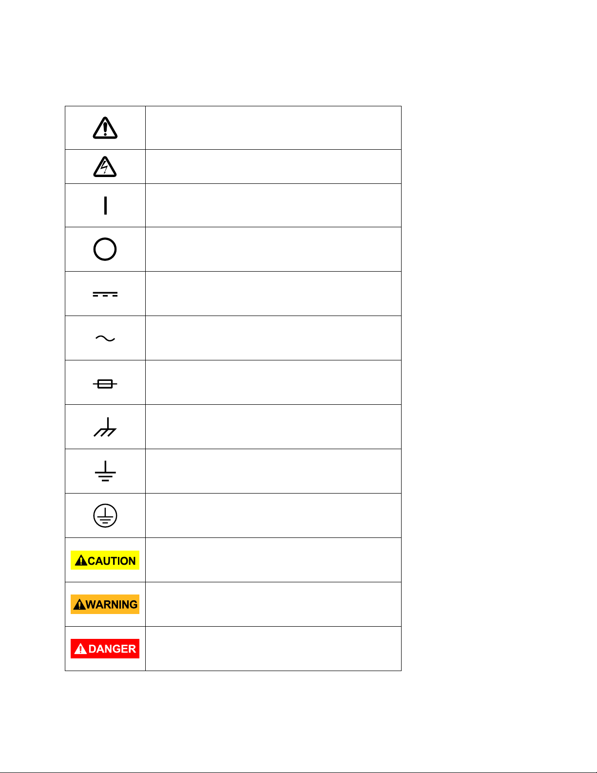
Safety Symbols
Refer to the user manual for warning information
damage to instrument.
On (Supply). This is the AC mains
instrument.
Off (Supply). This is the AC mains
instrument.
to avoid hazard or personal injury and prevent
Electric Shock hazard
connect/disconnect switch on the front of the
connect/disconnect switch on the front of the
DC current
Alternating current
Fuse Symbol
Chassis (earth ground) symbol
Ground terminal
Protective earth ground
CAUTION indicates a hazardous situation which, if
not avoided, will result in minor or moderate injury
WARNING indicates a hazardous situation which, if
not avoided, could result in death or serious injury
DANGER indicates a hazardous situation which, if
not avoided, will result in death or serious injury.
ix
Page 11

Table of Contents
Safety Summary ................................................................................................... i
Compliance Statements ............................................................................................................. vii
Safety Symbols ............................................................................................................................ ix
1 General Information ..................................................................................... 1
1.1 Product Overview ............................................................................................................. 1
1.2 Package Contents ............................................................................................................. 1
1.3 Product Dimensions ......................................................................................................... 2
1.4 Front Panel Overview ....................................................................................................... 3
Front Panel Description ........................................................................................................... 3
1.5 Rear Panel Overview ........................................................................................................ 5
Rear Panel Description ............................................................................................................ 5
1.6 Display Overview .............................................................................................................. 6
Display Description .................................................................................................................. 6
2 Getting Started ............................................................................................. 7
2.1 Input Power and Fuse Requirements ............................................................................... 7
Input Power ............................................................................................................................. 7
Fuse Requirements .................................................................................................................. 8
Fuse Replacement ................................................................................................................... 8
2.2 Output Connections ......................................................................................................... 8
2.3 Preliminary Check ............................................................................................................. 9
Self-test Errors ....................................................................................................................... 10
Output Check ......................................................................................................................... 10
Check Model and Firmware Version ..................................................................................... 11
3 Front Panel Operation ................................................................................ 12
3.1 Menu Options ................................................................................................................. 12
How to Access the Menu ....................................................................................................... 12
3.2 Configure Voltage and Current Output .......................................................................... 13
Setting Voltage ...................................................................................................................... 13
Setting Current ...................................................................................................................... 14
Remote Sense ........................................................................................................................ 14
x
Page 12

3.3 Protection Settings ......................................................................................................... 16
Configure Over Voltage Protection (OVP) ............................................................................. 16
Configure Maximum Power Limit ......................................................................................... 17
3.3 SYSTEM Menu ................................................................................................................ 18
Restore Factory Default Settings ........................................................................................... 18
Configure Power-On State ..................................................................................................... 19
Configure Trigger Source ....................................................................................................... 19
Save/Recall Instrument Settings ........................................................................................... 19
Enable/Disable Key Sound ..................................................................................................... 21
Remote Interface Setup ......................................................................................................... 21
Return Meter ......................................................................................................................... 24
3.4 CONFIG Menu ................................................................................................................. 24
Load Setup Option ................................................................................................................. 25
External Analog Control ........................................................................................................ 25
Configure Voltage Limit ......................................................................................................... 30
Parallel/Series Connection .................................................................................................... 31
Connection and Setup ........................................................................................................... 31
3.5 Program Sequence Mode (List mode) ............................................................................ 34
Configure Sequence Parameters ........................................................................................... 35
Configure Program (List) ....................................................................................................... 38
Recall and Run Program ........................................................................................................ 41
3.6 9115-AT Automotive Test Functions .............................................................................. 42
DIN 40839 Parameters .......................................................................................................... 42
ISO 16750-2 Parameters ....................................................................................................... 44
3.7 Configure Voltage Slope ................................................................................................. 50
3.8 Key Lock .......................................................................................................................... 52
4 Remote Operation ...................................................................................... 53
4.1 Interface Connection ...................................................................................................... 53
RS-232 ................................................................................................................................... 53
GPIB ....................................................................................................................................... 53
RS-485 ................................................................................................................................... 54
USBTMC ................................................................................................................................. 54
4.2 Remote Commands ........................................................................................................ 55
xi
Page 13

5 Troubleshooting Guide ............................................................................... 56
General .................................................................................................................................. 56
Remote Control ..................................................................................................................... 56
6 Specifications ............................................................................................. 57
7 Calibration .................................................................................................. 58
SERVICE INFORMATION ..................................................................................... 59
LIMITED ONE-YEAR WARRANTY ........................................................................ 60
xii
Page 14

1 General Information
1.1 Product Overview
B&K Precision models 9115, 9115-AT, and 9116 are multi-range single output high power
supplies with the capability of producing up to 80 V or 60 A (9115/9115-AT) and 150 V or 30 A
(9116) at a maximum power output of 1200 W. With an easy-to-read VFD display, user-friendly
controls and a numeric keypad that allows for easy configurations from the front panel.
Standard RS232, USB, GPIB, and RS485 interfaces included on the rear panel provide flexibility
for remote operation of the power supply. Its compact 1U size form factor makes it ideal for
use in a standard 19-inch rack.
Features:
• Multi-ranging operation provides voltage and current flexibility
• Compact, high density 1U rackmount form factor
• High programming and readback resolution of 1mV/1mA
• Standard USBTMC, GPIB, RS232, and RS485
• External analog interface with control and monitoring functions
• Master/Slave Mode for series and parallel connectivity
• Adjustable voltage slope (rise and fall time)
• Sequence programming
• OVP and OPP protection
1.2 Package Contents
Please inspect the instrument mechanically and electrically upon receiving it. Unpack all items
from the shipping carton, and check for any obvious signs of physical damage that may have
occurred during transportation. Report any damage to the shipping agent immediately. Save the
original packing carton for possible future reshipment. Every power supply is shipped with the
following contents:
• 1 x 9115, 9115-AT, or 9116 Power Supply
• 1 x User Manual
• 1 x AC Power Cord
• 1 x Certificate of Calibration
• 1 x Test Report
Verify that all items above are included in the shipping container. If anything is missing, please
contact B&K Precision.
1
Page 15
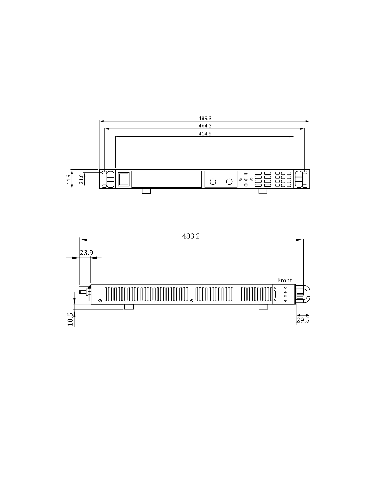
1.3 Product Dimensions
The 9115, 9115-AT, and 9116 power supply’s dimensions (WxHxD) are approximately 414.5 mm
x 44.5 mm x 483.2 mm (16.29” x 1.75” x 19.02”). It is designed to fit in a standard 19-inch
rackmount and is of 1U size.
Note: All dimensions in the figures below are measured in millimeters (mm).
Figure 1.1 - Front Panel View for 9115/9115-AT/9116
Figure 1.2 – Side View for 9115/9115-AT/9116
2
Page 16
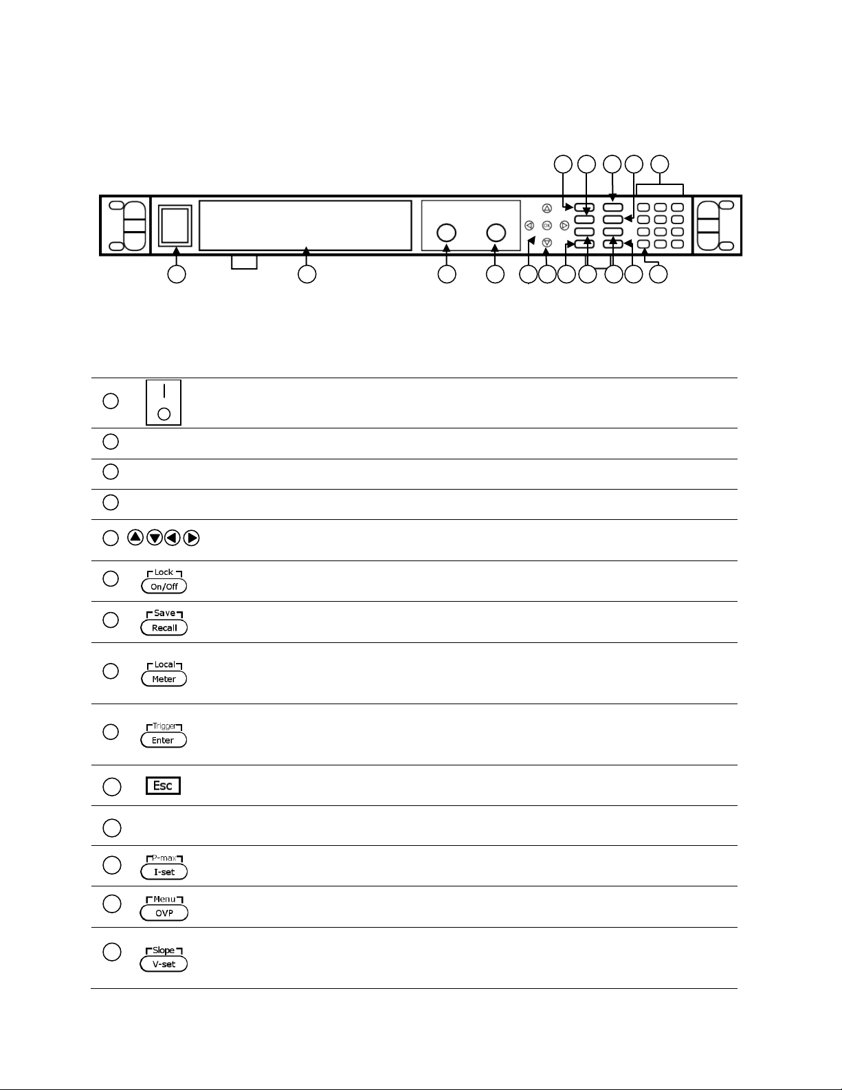
Up/Down/Left/Right arrow keys
Used to adjust cursor location and selecting menu items.
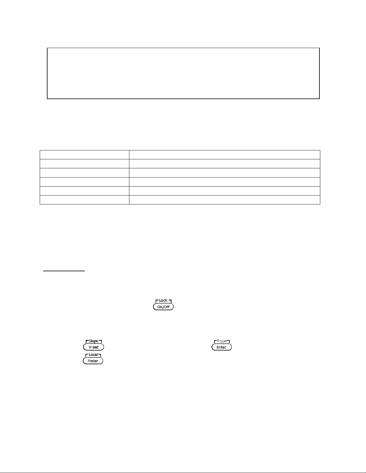
On/Off / Lock button
Control the output state or locks the front panel button.
Save/Recall button
Used to save and recall instrument settings.
Meter display toggle / Local button
to set the instrument back to local mode.
Enter / Trigger button
list operation.
Escape button
Used to exit menu settings.
I-set / P-max button
Used to configure output current or set the maximum power output limit.
OVP set button
Used to configure over voltage protection (OVP) value.
V-set / Slope button
voltage.
1 2 3 4 5
10
15
12
13
14
8 9 6 7 16
11
1 2 3 4 5
6
7
8
14
12
13
9
10
11
Figure 1.3 - Front Panel for 9115/9115-AT/9116
1.4 Front Panel Overview
Front Panel Description
Power On/Off switch
VFD display
Voltage adjust knob
Current adjust knob
Used to toggle display between setting and measured voltage and current or
Used to confirm setting/parameter changes or to provide a single trigger for
Numeric keypad
Used to configure output voltage or set the rise and fall time of the output
3
Page 17

Shift key
labeled in white)
OK button
(same as Enter button)
15
16
OK
Enables access to secondary functions of some buttons (These functions are
4
Page 18
1 2 3 3 4
5 6 7
8
9
10
1
2
3
4 5 6
7
8
9
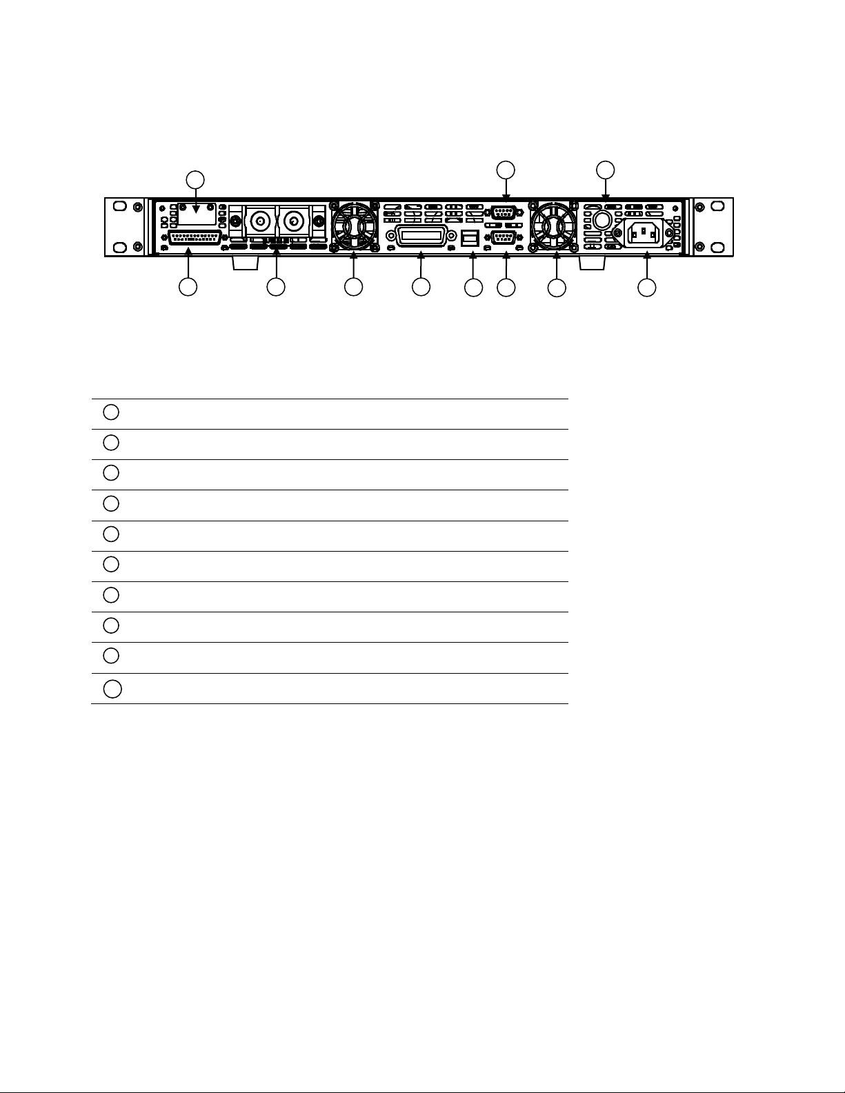
Figure 1.4 - Rear Panel for 9115/9115-AT/ 9116
10
1.5 Rear Panel Overview
Rear Panel Description
Analog Control Interface
Output Terminal
Rear Cooling Fan
GPIB Interface
USB Interface
RS-232 Interface
AC Input Receptacle
Fuse Box
RS-485 Interface
Remote Sense Terminals
5
Page 19
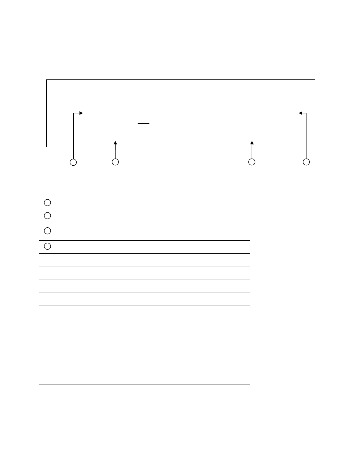
Settings Display
Displays parameter settings such as OVP, P-max, Rise/Fall
80.000V
12.000A
0.0W
OFF CC CV Rmt Addr Error Trig Prot * Shift
V
OVP
= 85.000 V
1
2 3 4
1 2 3
4
Figure 1.5 – Display Overview
1.6 Display Overview
Display Description
Setting/Measured Voltage
Measured Power Output
Setting/Measured Current
OFF Indicates output is disabled
CC Indicates constant current (CC) operation
CV Indicates constant voltage (CV) operation
Rmt Indicates remote mode
Addr Indicates remote communication activity
Error Indicates an error has occurred
Trig Indicates waiting for trigger (for list operation)
Prot Indicates protection trip for over voltage or over temperature
* Indicates key lock is enabled
Shift Indicates shift mode (for access to secondary button functions)
6
Page 20
warranty.
create a shock hazard.
SHOCK HAZARD
third conductor. Verify that your power outlet is of the
to earth ground.
2 Getting Started
Before connecting and powering up the instrument, please review and go through the
instructions in this chapter.
2.1 Input Power and Fuse Requirements
Input Power
Before connecting to an AC outlet or external power source, be sure that the power switch is in
the OFF position and verify that the AC power cord, including the extension line, is compatible
with the rated voltage/current and that there is sufficient circuit capacity for the power supply.
Once verified, connect the cable firmly.
The included AC power cord is safety certified for this
The supply has a universal AC input that accepts line voltage input within:
AC Input: 115 V (+/-10%) or 230 V (+/- 10 %)
Frequency: 47 Hz – 63 Hz
instrument operating in rated range. To change a
cable or add an extension cable, be sure that it can
meet the required power ratings for this instrument.
Any misuse with wrong or unsafe cables will void the
Do NOT plug the AC power cord into the wall socket
prior to connecting ALL three AC power wires to the
rear panel and securely mount the safety metal
housing over the input receptacle. Doing so may
The power cord provides a chassis ground through a
three-conductor type with the correct pin connected
7
Page 21
damage the power supply or cause a fire hazard
Model
Fuse Description
All Models
15AT / 250V (6 x 32 mm slow blow ceramic tube fuse)
short circuit output current. It will also prevent large voltage drops
Connection of this power supply to an AC power
source should be made by a qualified electrician or
other qualified personnel. Incorrect wiring may
Fuse Requirements
An AC input fuse is necessary when powering the instrument. Refer to the table below for the
fuse requirements.
Table 2.1 – AC Input Fuse Table
Fuse Replacement
Follow the steps below to replace or check the fuse.
1. Locate the fuse box in the rear panel, next to the AC input receptacle.
2. Use a flat blade screwdriver and turn the fuse capsule counter-clockwise. There is an
internal spring that will push it out after turning a few times.
3. Pull out the glass tube fuse inside to check and replace as necessary.
4. Insert the fuse capsule in the same location and use the flat blade screwdriver to turn
clockwise.
5. The fuse capsule will now be locked and secured.
2.2 Output Connections
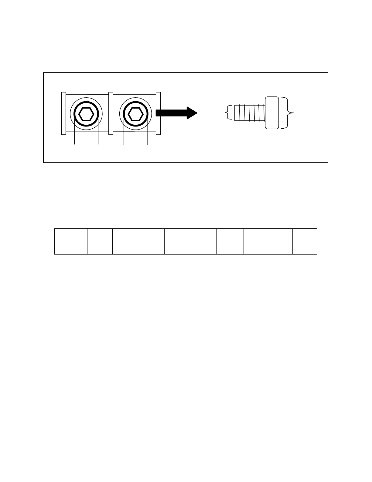
The main DC output terminal is a screw type terminal located in the rear panel. Figure 9 below
illustrates the size and dimensions of the terminal. To loosen, use hex key #4 size screwdriver.
Note: The screws on the terminals can be completely removed to allow for ring type adapters
(must be greater than 6mm in diameter).
Before connecting wires to the output terminals, turn OFF the power
supply to avoid damage to the instrument and the device under test
(DUT). For safety, load wires must have a wire gauge size large enough
to prevent overheating when the power supply operates at maximum
8
Page 22
from resistances in the wires.
AWG
6 8 10
12
14
16
18
20
22
Imax(A)
75
55
40
25
20
13
10 7 5
mΩ/meter
1.3
2.1
3.3
5.2
8.3
13.2
21
33.5
52.8
10mm
10mm
Rear Output Terminal
10mm
6mm
Hex Key Screw
Figure 2.1 - Rear Output Terminal
Due to the high current rating of the power supply, proper wire sizes are necessary for safe
connectivity and to prevent wires from overheating. Refer to the table below as a reference for
proper wire sizes according to the amount of current used for operation:
Table 2.2 - Wire Gauge Rating
2.3 Preliminary Check
Complete the following steps to verify that the power supply is ready for use.
1. Verify AC Input Voltage
Verify and check to make sure proper AC voltages are available to power the instrument.
The AC voltage range must meet the acceptable specification as explained in “2.1 Input
Power and Fuse Requirements”.
2. Connect Power and Self-Test
Connect AC power cord to the AC receptacle in the rear panel and press the power
switch to the |(ON) position to turn ON the instrument. It will run through a self-test
procedure with the screen shown in below:
9
Page 23
Error Message on Display
Description
EEPROM FAILURE
The internal EEPROM is corrupted or damaged.
Config Data Lost
The last operation data within the EEPROM is lost.
Calibration Data Lost
Calibration data within the EEPROM is lost.
FactoryCal.Data Lost
Factory calibration data is lost.
MainframeInitialize Lost
The system settings within the EEPROM is lost.
System Selftest . . . .
. .
Self-test Errors
The following errors will be displayed if self-test did not complete successfully:
If any of these errors occur, please contact B&K Precision.
Output Check
Voltage Check
Follow the steps below to check basic voltage output with no load connected.
1. Turn on the power supply. The display will show the OFF annunciator above the voltage
display.
2. Enable the output by pressing , and the button will be lit. The OFF annunciator
will change to CV.
3. Using the numeric keypad or the voltage adjust knob and enter a voltage value. The
voltage display will now show the value you entered. If entering with numeric keypad,
press first, then enter the value and press .
4. If the button is not already lit, press it once and the voltage display will show
the measured voltage at the output, which may fluctuate slightly from the voltage value
entered in the previous step.
5. (Optional) You may also verify the output voltage by connecting the (+) and (-) terminals
on the rear panel to an external voltmeter. The measured value should match or be
within the entered voltage value.
10
Page 24

Power Info . . .
Model: BK9115 Ver: 0.02 – 0.01
OK
Current Check
Follow the steps below to check basic current output of the power supply.
1. Turn on the power supply. The display will show the OFF annunciator above the voltage
display. Be sure that the output is disabled (the should not be lit when it is off).
If not, press to disable output.
2. Short the (+) and (-) output terminals with test leads, shorting bar, or clip. (Refer to
“Table 2.2 - Wire Gauge Rating” to select appropriate test leads)
3. Using the numeric keypad or the current adjust knob, enter a small current value (i.e.
1.000 A). If entering with numeric keypad, press first, then enter the value and
press . The current display will now show the value you entered.
4. Enable the output by pressing , and the button will be lit. The OFF annunciator
will change to CC.
5. If the button is not already lit, press it once and the current display will show
the measured current at the output, which may fluctuate slightly from the current value
entered in step 3.
6. (Optional) You may also verify the output current by connecting either the (+) and (-)
terminals on the rear panel to an external current meter capable of measuring the
current that you set. The measured value should match or be within the entered
current value.
7. Press the power switch to (OFF) position to turn off the power supply and remove
the short on the output terminals.
Check Model and Firmware Version
The model and firmware version can be verified by using the *IDN? query remote command. It
can also be found from within the menu system by following these steps:
1. Press and press to enter the menu system.
2. Press the arrow three times until INFO is blinking. Press , and the display will
show the following screen:
3. The model is shown above as BK 9115, and the firmware version is shown as 0.02 – 0.01.
4. Press twice to exit the menu and return to the normal display.
11
Page 25

SYSTEM
Initialize
Reset power supply settings to factory default values.
Power-On
Configure power-on state.
Trigger
Configure Trigger.
Memory
Select memory location for save/recall instrument settings.
Buzzer
Enable/Disable key sound.
Communication
Select communication interface.
ReturnMeter
Enables automatic delay to switch display from setting to
measured value (meter).
CONFIG
Load
Enables dummy load to increase speed of voltage fall time.
Ext-Ctrl
Configures external analog control.
Limit
Configures voltage setting limits.
Online
Configures series/parallel connection and master/slave mode.
LIST1
Off
Recall
Recall list file.
EditList
Configure list operation.
EditSeq
Configure sequence operation.
FUNC2
LIST
Setup the LIST operation
DIN40839
Configure a DIN40839 test
ISO16750-2
Configure a ISO16750-2 test
INFO
Show model, firmware version, and serial number.
3 Front Panel Operation
3.1 Menu Options
All settings and parameters can be configured from the built-in menu system of the power
supply. To access the menu, press and press .
The menu system is divided into the following sections and organized as follows:
1
Available on models 9115/9115-AT and 9116 only
2
Available on model 9115-AT only (LIST mode can be found in the menu)
How to Access the Menu
Before using the instrument, it is important to be familiarized with its menu structure and learn
how to view or change settings and parameters. Follow the steps below to guide you in
selecting menu options.
12
Page 26

SYSTEM MENU
Initialize Power-On
1. From the normal display, press and press to enter the menu.
2. The selected item will be blinking. Use keys to move through the menu selections.
3. When the desired menu section is blinking, press to access its menu settings.
4. Below is the display when SYSTEM is selected.
5. The selected item will be blinking. Use keys to move through the menu items.
When there is a on the right side of the display, that means there are more menu
items available to select from. Similarly, a will appear on the left side of the display
when there are menu items to the left. Use the keys accordingly to select the
desired menu item.
6. Press to access the selected menu item.
7. There may be parameters or options to select within each menu item. Follow the same
instructions as described in the previous steps to select them. To save changes to a
setting, press .
8. To exit the menu at any time, press twice.
3.2 Configure Voltage and Current Output
Voltage and current can be set from the front panel. Remote sense is also available on the rear
panel for voltage compensation at the output.
Setting Voltage
Follow the steps below to set the output voltage:
1. From the normal front panel display, users can use either the voltage adjust knob or the
numeric keypad to enter the setting voltage.
2. If entering using numeric keypad, press first so that the cursor selects the
voltage display. Then, enter the value and press to set the voltage.
3. To change the cursor position to adjust with the voltage adjust knob, use the keys
to move left or right.
13
Page 27

Note: To see the changes to the setting voltage, be sure the display is not showing the
If it is not lit, display is showing setting voltage.
Note: To see the changes to the setting current, be sure the display is not showing the
If it is not lit, display is showing setting current.
measured voltage. This can be checked by looking at the button backlight.
Setting Current
Follow the steps below to set the output current:
1. From the normal front panel display, users can use either the current adjust knob or the
numeric keypad to enter the setting current.
2. If entering using numeric keypad, press first so that the cursor selects the
current display. Then, enter the value and press to set the current.
3. To change the cursor position to adjust with the voltage adjust knob, use the keys
to move left or right.
measured current. This can be checked by looking at the button backlight.
Remote Sense
Remote sense can be used to compensate for voltage drops (up to 1 V) due to resistance from
test leads connected to your device under test (DUT), thus providing more accurate output
voltage. The power supply is initially setup to local sense mode by default. Refer to the
following sections for details of local and remote sense setup.
Local Sense
By default, the power supply is setup for local sense. This is determined by the wire
connections in the rear panel, illustrated below:
14
Page 28

a shock hazard under high voltage output conditions.
Vo+
Vs+
Vo-
Vs-
Figure 3.1 – Local Sense Connection Diagram
DO NOT disconnect the wires if remote sense is not used. Doing so will cause
erratic behavior and may damage the power supply under certain conditions.
Never connect any power source into any of the four terminals at any time
during operation.
When output is enabled, DO NOT use your hands to touch the terminals or the
screws that are designed to tighten wires to the terminals. Doing so may create
Remote Sense
To enable remote sense, follow the steps below:
1. Power OFF the supply and disconnect all loads and cables connected to it.
2. Use a small flat blade screwdriver to loosen the wire connection connected between
Vo+ and Vs+ and Vs- and Vo-.
3. Connect the Vs+ to the DUT’s positive (+) terminal, and connect the Vs- to the DUT’s
negative (-) terminal.
4. Do not connect any wires to Vo+ and Vo- terminals.
5. Power ON the power supply, and then configure and enable the output. The setup
should look like the figure below:
15
Page 29

Vo+
Vs+
Vo-
Vs-
Rear Output Terminal
Rear Sense Terminal
+
-
Figure 3.2 – Remote Sense Connection Diagram
DUT
DO NOT at any time disconnect the wires from the Vs+ and Vs- terminals to the
DUT while output is enabled (ON). Doing so may damage the power supply and
cause unstable output.
3.3 Protection Settings
Configure Over Voltage Protection (OVP)
Follow the steps below to set the OVP limit:
1. Press the button. The display will show V
voltage adjust knob or the numeric keypad to enter the OVP limit.
2. Press to save the change. The display will then show T
specifies the delay time to which to activate OVP.
3. Use the voltage or current adjust knob or the numeric keypad to enter a value. This can
be from 1 ms – 600 ms.
on the bottom right. Use the
OVP
. This parameter
OVPdly
4. Press to save the change. OVP is now configured. Notice the backlight
will turn on. This means OVP is enabled.
16
Page 30

80.000VOVP
12.000A
0.0W
OFF Prot
5. To disable OVP at any time, just press twice. When it is disabled, the backlight
will disappear.
When OVP protection is tripped, the following screen will display:
To clear the trip status, press once.
Configure Maximum Power Limit
Follow the steps below to set the maximum power limit:
1. Press and then . The display will show P
the voltage or current adjust knob or the numeric keypad to enter the maximum power
output limit.
2. Press to save the change.
3. Use the voltage or current adjust knob or the numeric keypad to enter a value. This can
be from 1 ms – 600 ms.
4. Press to save the change. OVP is now configured. Notice the backlight
will turn on. This means OVP is enabled.
5. To disable OVP at any time, just press twice. When it is disabled, the backlight
will disappear.
When the output reaches the power maximum limit, the over power protection is tripped and
the following screen will display:
on the bottom right. Use
max
17
Page 31

settings and parameters back to their default values.
Communication Address
0
Key Sound
ON
Trigger Mode
Manual
Communication Interface
RS232
RS232 Settings
4800, 8, N, 1
Return Meter
Off
Memory
Group 0
80.000VOPP
12.000A
0.0W
OFF Prot
To clear the trip status, press once.
3.3 SYSTEM Menu
All setup procedures and settings explained in this section can be accessed from the SYSTEM
menu. To access this menu, press and press . When SYSTEM is blinking, press
.
Restore Factory Default Settings
All instrument settings can be reset back to their factory default values by doing the following:
Restoring the instrument to factory default will change all current instrument
1. From the SYSTEM menu, select Initialize and press .
2. The instrument will return to the normal display and all settings are now restored back
to factory default. The below table lists some of the factory default settings.
Table 3.1 - Factory Default Settings
18
Page 32

Power-On
Rst
Load Setup
Off
External Control
10v-M
Limit
Vmin = 0.000V, Vmax = 81.000V
Online Setup
Off
Output
Disabled
Configure Power-On State
The initial power-On state of the power supply can be configured by following the steps below:
1. From the SYSTEM menu, select Power-On and press .
2. There are two options:
Rst(Def) – Factory Default.
Sav0 – Settings before last power up.
3. Select the settings you want during power up, and press to save changes.
4. To exit the menu at any time, press twice.
Configure Trigger Source
The trigger function is used to initiate the start of running a program sequence (list). The trigger
source can be set so that users can send a trigger from the front panel or through a remote
command via remote interface. Follow the below steps to configure the trigger mode:
1. From the SYSTEM menu, browse and select Trigger and press .
2. There are two options:
Manual(Def) – Manual trigger. Front panel trigger button is used to send a trigger
(press and to send trigger).
Bus – Bus trigger. Remote command *TRG is used to send a trigger.
3. To exit the menu at any time, press twice.
Save/Recall Instrument Settings
The instrument can save up to 100 instrument settings in non-volatile memory. Memory is
allocated in 10 different storage groups (group 0 to 9), and each group has 10 memory locations
19
Page 33

80.000V
12.000A
Save Data to Bank : 0
OFF
MEMORY
Group = 0
to store settings (0 to 9). The memory group must be selected from the menu first, before
settings can be saved within the group.
Select Storage Group
1. From the SYSTEM menu, browse and select Memory and press . The following
screen will appear.
2. Use the current adjust knob or the numeric keypad to enter the storage group. Select
between 0 – 9. Press to save selection.
3. To exit the menu at any time, press twice.
Save Settings
1. Set up all the instrument settings that you want to save.
2. Then, press and . The display will show the following:
3. Use the current adjust knob or the numeric keypad to enter the memory location in
which to store current instrument settings. Select between 0 – 9. Press to save
to the selection location.
4. If it saved successfully, there will be a message on display: Save Success!
Recall Settings
20
Page 34

Note: When in Recall mode, users can recall settings from different locations
in location 5 on the fly.
1. Press . Notice the button will be lit and the cursor on the display will disappear.
This indicates Recall mode. Instrument settings can only be recalled when the
instrument enters this mode.
2. Use the keypad to enter the memory location you want to recall. Enter between 0 to 9.
3. Once entered, the saved settings at the location will be immediately recalled.
without having to press additional keys each time. For example, you can
press 1 to recall settings in location one, and then press 5 to recall settings
4. To exit Recall mode, press and it will no longer be lit. The cursor on the display
will reappear, indicating that the instrument is no longer in Recall mode.
Enable/Disable Key Sound
The instrument initially has key sound enabled from factory. To disable or re-enable the key
sound, follow the steps below:
1. From the SYSTEM menu, browse and select Buzzer and press .
2. Select between the two options:
On(Def) – Enable key sound
Off – Disable key sound
3. Select the desired option and press to save the change.
4. To exit the menu at any time, press twice.
Remote Interface Setup
There are several interfaces available for remote communication: USBTMC, GPIB, RS-232, and
RS-485. This section will described how to setup all the supported interfaces.
Note: The RMT indicator will appear on display when the power supply is successfully
connected to a PC remotely through any remote interface. Keys on the front panel will be
locked until the instrument is in LOCAL mode. To return to LOCAL mode from the front panel,
press and . The RMT indicator will disappear when the instrument is in LOCAL
mode.
21
Page 35

Note: The default is 4800, 8, N, 1, Address = 0.
Note: Users who have LabVIEW™ or NI-VISA installed will automatically have this
RS232
4800 , 8 , N , 1 , Addr . . .
RS-232
Follow the steps below to configure the power supply for RS-232 operation:
1. From the SYSTEM menu, browse and select Communication and press .
2. Select RS-232(Def) and press to set to RS-232 for remote communication. The
following display will be shown:
3. 4800 is the baudrate; 8 is the data bits; N is the parity; 1 is the stop bit; Addr… is for
address.
4. Use to select between each serial settings, and use to change the settings.
5. Below lists the options that can be changed for each setting:
Baudrate: 4800, 9600, 19200, 38400, 57600, 115200*
Data bits: 8
Parity: N (None), E (Even), O (Odd)
Stop bit: 1, 2
Addr: 0 to 31
*Setting the baudrate to 115200 may cause unstable results during remote
communication. Select a lower baudrate if communication errors occur.
6. All serial settings must match with the settings configured on the PC in order for
communication to link successfully.
USBTMC
A USB Type A to Type B cable (i.e. USB printer cable) is required to connect the USB port in the
rear panel to a PC. Follow the steps below to setup the power supply for remote
communication.
1. From the SYSTEM menu, browse and select Communication and press .
2. Select USB and press to set to USBTMC for remote communication.
3. Install the USB driver. For Windows® 7 users, this may install automatically. For other
users, visit www.bkprecision.com to download the driver.
driver in their system. In this case, driver download is not required.
22
Page 36

Note: The default is 4800, 8, N, 1, Address = 0.
RS485
4800 , 8 , N , 1 , Addr . . .
GPIB
Follow the below instructions to select GPIB interface for remote operation.
1. From the SYSTEM menu, browse and select Communication and press .
2. Select GPIB and press to set to GPIB for remote communication.
3. The display will give a prompt to select an Address. This is the GPIB address to which
the power supply will be assigned to.
4. Use the current adjust knob or the numeric keypad to enter an address from 0 – 31.
5. Press to save the selected address and the display will return to the
Communication menu.
6. Press several times to exit the menu.
RS-485
Multiple power supplies (up to 31) can be connected together in series and be controlled via
the DB-9 RS-485 interface.
1. From the SYSTEM menu, browse and select Communication and press .
2. Select RS485 and press to set to RS485 for remote communication. The
following display will be shown:
3. 4800 is the baudrate; 8 is the data bits; N is the parity; 1 is the stop bit; Addr… is for
address.
4. Use to select between each serial settings, and use to change the settings.
5. Below list the options that can be changed for each setting:
Baudrate: 4800, 9600, 19200, 38400, 57600, 115200*
Data bits: 8
Parity: N (None), E (Even), O (Odd)
Stop bit: 1, 2
Addr: 0 to 31
*Setting the baudrate to 115200 may provide unstable results during remote
communication. Select a lower baudrate if communication errors occur.
23
Page 37

6. Select Addr… and press . You will be prompted to enter an address. Use current
adjust knob or numeric keypad to enter a number between 0 to 31, and then press
.
7. For each power supply that you want to control, provide a different address. For
example, if you have three power supplies to control, set the first supply to address 1,
second supply to address 2, and third supply to address 3. If two or more supplies have
the same address, the RS485 protocols will create communication errors.
8. Repeat the above steps for each power supply that you want to connect together and
control, making sure that each of them have a different address assigned.
9. Press several times to exit the menu.
Return Meter
This option allows users to enable an internal fixed timer delay (5 seconds) for the power supply
to automatically switch from setting display to measured display. When enabled, if the power
supply output state is ON (enabled) and if the display shows setting voltage and current, it will
automatically switch to measured voltage and current display after 5 seconds. The backlight of
the button will also be lit. In this state, pushing the again to toggle back to
setting display will reset the 5-second timer again before the supply changes back to measured
display.
To configure this option, follow the steps below:
1. From the SYSTEM menu, browse and select ReturnMeter and press .
2. Select between the two options:
Off(Def) – Return Meter function disabled.
Delay – Enables return meter function.
3. Select the desired option and press to save the change.
4. To exit the menu at any time, press twice.
3.4 CONFIG Menu
All setup procedures and settings explained in this section can be accessed from the CONFIG
menu. To access this menu, press and press . Select CONFIG, then press
.
24
Page 38

flow and damage the power supply and the dummy load.
Note: Voltage monitoring is on Pin 23 and current monitoring is on Pin 24 of the DB25
Analog interface.
Load Setup Option
The power supply has an internal dummy load that can be enabled to increase the speed of the
voltage fall time for high speed test applications. The effectiveness of this function is
dependent on the DUT (device under test) and may or may not be useful for some applications.
This feature should only be used with caution, as it is not designed for all applications.
DO NOT enable this function for applications such as connecting devices for battery charging
or powering electric motors. All other applications that may behave similarly to these types
of loads should NOT use this function. This function is disabled by default.
DO NOT enable this function for battery test applications (i.e. battery charging) and all
applications that may have a high charge. If a battery with a low voltage is connected to
the power supply while the output is OFF (disabled), the dummy load will drain the
battery. If the battery capacity is large and this function is enabled, a large current will
To enable or disable this function, follow the steps below:
1. From the CONFIG menu, select Load and press .
2. Select between the two options:
Off – Disables the dummy load (default).
On – Enables the dummy load.
3. Select the desired option and press to save the change.
4. To exit the menu at any time, press twice.
External Analog Control
The power supply output can be controlled and monitored by external DC voltage sources (0 – 5
V or 0 – 10 V) or resistances (0 – 5 kΩ or 0 – 10 kΩ).
Configure Monitoring Source
Follow the steps below to configure the source to use for monitoring.
25
Page 39

Note: Voltage programming is on Pin 20 and current programming is on Pin 22 of the
DB25 Analog interface.
Ext – Ctrl Setup
10v- M 10v/10k-P V-P Off
Ext – Ctrl Setup
10v- M 10v/10k-P V-P Off
1. From the CONFIG menu, browse and select Ext-Ctrl and press . The following
screen will display:
2. Select 10v-M or 5v-M so that it is blinking. Use the keys to change between 10v-
M and 5v-M. – 0 – 5 V scale is used for monitoring 0 – 100% of output.
10v-M – 0 – 10 V scale is used for monitoring 0 – 100% of output.
3. Press when finished making the selection.
4. Press several times to exit the menu.
Configure Control Source
Follow the steps below to configure the source to use for programming the voltage and current
output.
1. From the CONFIG menu, browse and select Ext-Ctrl and press . The following
screen will display:
2. Select the second item 10v/10k-P or 5v/5k-P so that it is blinking. Use the keys
to change between 10v/10k-P and 5v/5k-P.
5v/5k-P – 0 – 5 V (for voltage) or 0 – 5 kΩ (for resistance) is used for programming the
voltage and current output.
10v/10k-P – 0 – 10 V (for voltage) or 0 – 10 kΩ (for resistance) is used for programming
the voltage and current output.
26
Page 40

Ext – Ctrl Setup
10v- M 10v/10k-P V-P Off
Ext – Ctrl Setup
10v- M 10v/10k-P V-P Off
3. Press when finished making the selection.
4. Press several times to exit the menu.
Select Source Type
For external voltage and current programming of the output, users can configure the power
supply to be controlled with external DC voltages or resistances. Follow the instructions below
to select the source type.
1. From the CONFIG menu, browse and select Ext-Ctrl and press . The following
screen will display:
2. Select the third item V-P or R-P so that it is blinking. Use the keys to change
between V-P or R-P.
V-P – Use external DC voltage source for programming the output.
R-P – Use external resistance for programming the output.
3. Press when finished making the selection.
4. Press several times to exit the menu.
Enable/Disable External Analog Control
If external analog control is not used, it must be disabled before normal front panel operation
can resume. Follow the steps below to enable or disable external analog control.
1. From the CONFIG menu, browse and select Ext-Ctrl and press . The following
screen will display:
27
Page 41

feeding power into the control pins.
2. Select Off and press . This will disable external analog control. To enable, select
any of the three other menu items and press after selection.
3. When finished, press several times to exit the menu.
Pin Assignment
Below are the pin assignments of the analog interface.
Pin # Label Description
1 DGND Ground pin
14 EXT ON Control output state
15 SHUT_OFF Emergency shut off
16 POWER_OK Status output
18 CV_CC+ CV mode status
19 CV_CC- CC mode status
20 VPRG Voltage programming input
21 REF_10V 10V DC reference output
22 IPRG Current programming input
23 VMON Voltage monitoring output
Figure 3.3 - Analog Interface Pin Assignments
24 IMON Current monitoring output
13 AGND Ground pin
DO NOT input any voltages above 10 V DC or 10 kΩ resistance or below 0 V DC to any of
the 25 pins. Doing so will damage the power supply. The inputs also do not have reverse
polarity protection. Check your positive and negative connections carefully first before
Control Output State
28
Page 42

The output state of the power supply can be controlled by EXT_ON (pin 14) and DGND (pin 1).
Output ON State - Pin 14 and Pin 1 are connected/shorted together.
Output OFF State - Pin 14 and Pin 1 are opened and not connected together.
Emergency Shut Off
In the case where an emergency shut off to the output of the power supply is required,
SHUT_OFF (pin 15) and DGND (pin 1) is used.
To shut off, connect/short Pin 15 and Pin 1 to ge th er. This will bypass the analog control of the
output state and disable (OFF) the output. In this case, pin 14 and pin 1 will need to be
disconnected/opened from each other and reconnected to enable output again.
Power Supply Status
The power supply status can be monitored using POWER_OK (pin 16) output and DGND (pin 1).
During normal operating conditions, this pin will output 5 VDC. If OTP condition or other
abnormalities occur, this pin will output 0 VDC.
Monitoring Operation Mode
The operation mode of the power supply can be monitored using CV_CC+ (pin 18) and CV_CC(pin 19) output pins.
CV Mode – Pin 18 and Pin 19 will output 5 V DC.
CC Mode – Pin 18 and Pin 19 will output –5 V DC.
OFF – Pin 18 and Pin 19 will output 0 VDC.
Control Output Settings
The voltage and current output settings can be configured using an external source connected
to VPRG (pin 20) and Ground (pin 8) for voltage and IPRG (pin 22) and Ground (pin 10) for
current.
Follow the instructions in the previous sections for configuration and setup.
Monitor Output Settings
29
Page 43

Note: These pins are used for reference only and are not designed to power devices. Do
not connect a load across it.
Note: At any time during operation, when you are unable to set to a desired voltage,
check this voltage limit setting to make sure the set value is within range.
Voltage Range
Vmin = 0.000 V
The voltage and current output can be monitored using VMON (pin 23) and Ground (pin 11) for
voltage and IMON (pin 24) and Ground (pin 12) for current.
Follow the instructions in the previous sections for configuration of the voltage scale to use for
monitoring. The scale can be selected between 0 – 10 VDC or 0 – 5 VDC to reflect 0 – 100% of
voltage or current output.
Reference Voltage
A 10 VDC reference output is available on REF_10V (pin 21) and Ground (pin 9).
Configure Voltage Limit
The minimum and maximum set voltage can be configured on the power supply to limit the
settable voltage range for protection.
Follow the steps below to configure the voltage limits:
1. From the CONFIG menu, browse and select Limit and press . The following
screen will display:
2. With Vmin prompted, use the voltage or current adjust knob or the numeric keypad to
enter the minimum voltage limit value.
3. When finished, press , and the display will prompt with Vmax.
4. Enter the maximum voltage limit value the same way as in step 2.
30
Page 44

Note: Master/slave configurations and RS-485 connections must be properly set up prior
to function.
Model
Series
Parallel
9115 and 9115-AT
3 units (240 V Max)
3 units (180 A Max)
9116
2 units (300 V Max)
4 units (120 A Max)
damage to the power supplies and void the manufacturer’s warranty.
5. When finished, press . The screen will return to the CONFIG menu.
6. Press several times to exit the menu.
Parallel/Series Connection
More than one unit of the same model can be connected in a parallel or series configuration.
Table 3.2 below shows the total number of units that can be connected in each configuration.
The power supplies can be set up in master/slave mode so that the master unit can control all
other power supplies in the parallel or series connection.
to controlling the power supplies in parallel/series connection. However, RS-485
does not have to be set as the Communication interface for master/slave operation
Table 3.2 – Series/Parallel Configuration Table
Connecting more units in series/parallel than specified in the table above can cause
Connection and Setup
Connecting multiple power supplies in parallel or in series can increase the overall current
output or voltage output respectively. For this configuration to function properly, there are
several items that must be set up first. Follow the instructions in this section carefully for setup.
Connection
Determine the total number of power supplies that you want to connect in parallel or series.
Disable the output of the power supplies and power OFF the power supplies.
31
Page 45

to the output terminal.
Note: Be sure to use wires that can support the amount of output current that you want
to output from the power supplies. Refer to “2.2 Output Connections” for details.
- +
+ -
Figure 3.4 – Master/Slave Parallel Connection Diagram
Fo r s afety, always turn OFF the power supplies before connecting or disconnecting wires
For parallel connection:
Connect each power supplies’ positive (+) terminals together. Do the same for the negative (-)
terminals.
For series connection:
Connect one power supply’s positive (+) terminal to the negative (-) terminal of another. Do the
same for all the power supplies.
Then, connect all of the power supplies’ Pin 1 of the RS-485 interface together. Do the same for
Pin 5.
Below illustrates the connection diagram for parallel connection.
DUT
32
Page 46

Note: Configure Slave power supplies FIRST, and configure the Master power supply
LAST. For remote or front panel operation, only control the Master power supply.
Online Setup
Parallel Slave Addr… Off
- +
+ -
Figure 3.5 - Master/Slave Series Connection Diagram
DUT
Master/Slave Setup
Only one power supply has to be configured as a Master. The rest must be configured as Slave.
Up to 3 units can be configured in total.
Master/Slave Configuration
After physically connecting the power supplies for parallel or series operation, power ON the
power supplies and follow the steps below to configure a power supply as a master or slave.
1. From the CONFIG menu, select Online and press . The following will display:
2. While Parallel or Series is flashing, use keys to toggle between the two options.
Set to Parallel for parallel connection and Series for series connection.
33
Page 47

Sequence #1
Step 10..
Sequence #10
Step 10..
Program #1
Program #10
Run
Memory
Save
Recall
Figure 3.6 – List Mode Illustration
3. Press the key to select Slave or Master. Use the keys to select between the
two options. Select Master to set the power supply as a master, or select Slave to set
the power supply as a slave. Always set the Slave supplies first and Master supply last.
4. Press the key to select Addr…. Press and the display will prompt to enter an
address. Use the numeric keypad to enter an Address, which must be different than all
other power supplies that you want to connect together in parallel. Enter any number
between 0 – 31.
5. Press to save the changes.
6. Exit the menu by pressing several times.
3.5 Program Sequence Mode (List mode)
The power supply has a list mode feature that allows storing programmed sequences into
internal non-volatile memory and recalling and running them per configured parameters. A
total of 10 steps can be configured for each sequence, and a total of 10 sequences are available
for storage. Additionally, multiple sequences or all 10 sequences can be saved into a program
configuration, where each program configuration allows running one sequence after another.
This allows for a total maximum of 100 steps in one program configuration. Up to 10 program
configurations can be saved and recalled to and from the non-volatile memory. Below is an
illustration of how programmed sequences are structured, stored, and recalled.
Step 1..
Step 2..
..
Step 1..
Step 2..
..
Sequence #1
Sequence #2
..
Sequence #10
Program #
Sequence #2
Sequence #5
Sequence #7
Sequence #8
34
Page 48

Note: These configurations must be set up in order.
Note: It is recommended that the Trigger Source be configured prior to setting up the
prior to setting up the configurations.
Parameter
Adjustable Range
Voltage Setting
0.000 – < OVP Voltage
Current Setting
0.000 – *max. current setting
Width
0.001 seconds – 86400 seconds
Slope
0.002 seconds – 86400 seconds
There are three separate configurations to set up for programming and running a sequence (in
order):
1. Configure Sequence Parameters
2. Configure Program (List)
3. Recall and Run Program
The following sections will go into the details of setting up all three configurations.
configurations. Additionally, the output of the power supply must be disabled
Configure Sequence Parameters
Each sequence can store from 1 to 10 steps. Each step’s parameters contain voltage setting,
current setting, width (time to hold the step), and slope (voltage rise and fall). The adjustable
range for each of these parameters are specified in table below:
Table 3.3 - Step Parameter Range
*Maximum current and voltage setting cannot exceed maximum power configured under P-max setting.
As an example, follow the steps below to set up a sequence with fixed current limit of 1 A, as
illustrated below:
35
Page 49

SEQ
Active Step: 0987654321
V
S
1 2 3
1 s
2 s
3 s
3 s
4 s
Figure 3.7 - Program Sequence Example
1. Access the main menu by pressing and the .
2. Use the key to select LIST (FUNC. then press twice for model 9115-AT) and
press . The below screen will display:
3. Use the key to select EditSeq and press . The display will say EDIT SEQ and an
entry for Seq Name: is displayed.
4. Use the current adjust knob or the numeric keypad to select any number between 1 –
10 to edit its sequence. Press . Now, the following screen will display:
5. These numbers represent the step numbers of the sequence, where “0” represents step
number 10. At this point, use the numeric keypad and try to push any numbers 0 – 9.
Notice that the number you press will correspond to the number displayed in Active
Step and will toggle to display a “Y” in its place.
6. The “Y” represents a selection of the step number, making it an active step (meaning
the step is enabled in the sequence). For the steps you want to configure as active, use
the numeric keypad to select so that the corresponding number changes to “Y”.
36
Page 50

EDIT SEQ CURRENT
Seq Step 1 Current = 1.000A
EDIT SEQ VOLTAGE
Seq Step 1 Voltage = 1.000V
SEQ
Active Step: 09876YYYYY
SEQ
Active Step: 09Y7Y5Y32Y
Pressing the same number will change the “Y” back to the corresponding number. For
example, if you want to configure and store a sequence with steps 1, 4, 6, and 8, press 1,
4, 6, and 8 on the numeric keypad so that the following will display:
7. For this example, steps 1, 2, 3, 4, and 5 will be used, so use the numeric keypad and
press 1, 2, 3, 4, and 5 until it displays:
8. Once set, press . The display will change to the following:
9. This is prompting the user to enter the voltage setting for step 1. Use the voltage and
current adjust knob or the numeric keypad and enter 1.000. Then press .
10. The display will change to the following, prompting the user to enter the current setting
for step 1.
11. Similar to entering the voltage setting in the previous step, do the same to enter 1.000
as the current setting. Then press . Now, the following will display:
37
Page 51

SAVE SEQ
No Yes
EDIT SEQ SLOPE
Seq Step 1 Slope = 0.005s
EDIT SEQ WIDTH
Seq Step 1 Width = 1.000s
12. Enter the width, which is the time to hold the voltage and current setting configured in
the previous steps. Enter 1.000 (for 1 second). Press . Now, the following will
display:
13. Enter the slope, which defines the voltage slew rate (transition time between steps) for
step 1. Enter 0.005. Press .
14. Now, the display will return back to the display shown in step number 8, except it will
prompt the user to enter the voltage setting for step 2 of the sequence. Follow steps 8-
13 to configure step 2 with: 2V, 1A, 2s width, 0.005s slope. Then step 3 with: 3V, 1A, 3s
width, 0.005s slope. Then step 4 with: 1.5V, 1A, 3s width, 0.005s slope. Finally, step 5
with: 2.5V, 1A, 4s width, 0.005s.
15. After step 5 parameters are configured, the display will show the following to request
confirmation to save the step parameters into memory. Press key to select Yes and
press .
16. If stored successfully, the display will show a message Save Success! After a few
seconds, it will return to the LIST menu.
Configure Program (List)
38
Page 52

EDIT LIST POWER
List Power = 1200.0W
V
S
1 2 3
1 s
2 s
3 s
3 s
4 s
The sequence(s) to execute and run can be selected, as well as its repetitiveness. This means
multiple sequences can be run one after another. With 10 steps per sequence and up to 10
sequences configured, a program can run with a maximum of 100 steps.
As an example, take the sequence illustrated in the previous section as sequence #1, and
sequence #2 to run after sequence #1. Suppose sequence #2 is already stored into memory and
is illustrated as the following:
This example setup will run sequence #1 two times and sequence #2 three times, then repeat
five times. Follow the steps below to configure this:
1. From the LIST menu, use the key to select EditList and press . The display will
say EDIT LIST FILE with the prompt File Name: to ask to enter a file name number.
2. Use the current adjust knob or the numeric keypad to select any number between 1 –
10. This will be the location to store the program configurations. Press . Now,
the following screen will display:
3. This parameter is configured to limit the maximum power of the program (list) when it is
executed. Leave it default to 1200.0 for maximum power output. Press and the
following will display:
39
Page 53

Note: The maximum number of repeat times is 65535 times.
SEQ REPEAT
Seq 1 Repeat: 1
FILE
Active Seq: 09876543YY
FILE
Active Seq: 0987654321
EDIT LIST REPEAT
List Repeat = 1
4. The display prompts the user to enter the number of times to repeat the program (list).
For this example, enter 5 with the numeric keypad and then press .
5. The next display will show the following:
6. This is similar to step 5 and 6 in the previous section for Configure Sequence
Parameters. Each of the numbers on the display represents the sequence numbers
stored in memory, with “0” representing sequence # 10.
7. In this example, only sequence #1 and sequence #2 will be executed. Therefore, use the
numeric keypad and press 1 and 2 so that both of those numbers on the display will
toggle to “Y” in their places like the following:
8. Once these two sequences are selected (active), press to see the following:
40
Page 54

SAVE LIST
No Yes
9. The display prompts the user to enter the number of times to repeat sequence #1 as
part of the program (list). In this example, use the current adjust knob or the numeric
keypad to enter 2. Press and the same prompt will immediately follow for
sequence #2. Enter 3 and then press .
10. Now it will display the following to confirm saving the program (list).
11. Press key to select Yes and press to save the program (list) into memory.
12. If stored successfully, the display will show a message Save Success! After a few
seconds, it will return to the LIST menu.
Recall and Run Program
Once the sequence(s) and program are configured and stored into memory, they can be recalled
and triggered to run.
Recall Program
Follow the steps below to recall a stored program from memory:
1. From the LIST menu, use the key to select Recall and press . The display will
say RECALL LIST with the prompt Recall List File: to ask to enter a number.
2. This is the location number where the program is stored in. Select a number between 1
to 10 with the current adjust knob or the numeric keypad, then press .
3. The display will return back to the LIST menu.
Run Program
To run a program sequence after it is recalled, the trigger source must be configured first. Refer
to “Configure Trigger Source” in section 3.3 to set up the trigger source.
Follow the steps below to run the program:
1. Assuming the stored program has already been recalled, from the LIST menu, with Off
selected, press . The Trig indicator will appear at the top middle of the display.
41
Page 55

Note: If the Trigger Source is configured to BUS, use the remote command for sending
manual for details.
Note: This functionality is only available on model 9115-AT.
0.000V
0.000A
0.0W
OFF Trig
LIST
2. Now, press twice to exit the menu. The following will display:
3. If the display is showing the measured voltage and current value, the backlight
should be lit and display should show 0.000V and 0.000A.
4. Now, press the key to enable (ON) the output.
5. If the Trigger Source configured in section 3.3 is set to Manual (Def), then the front
panel trigger key can be used to initiate the program. Press and then .
6. The program will immediately start running and the backlight of the button will
be blinking. The Trig indicator will also disappear.
7. When the program ends, the will stop blinking and the Trig indicator will
reappear again.
triggers over any of the remote interface available. Refer to the programming
3.6 9115-AT Automotive Te st Functions
The 9115-AT power supply has a unique automotive testing feature built-in that allows the user
to run stress tests based on the DIN 40839 and ISO 16750-2 standards. The functions have the
ability to test 12 volt and 24 volt systems. For details on the DIN 40839 and ISO 16750-2
standards, please see www.din.de (DIN standards) and www.iso.org (ISO standards).
DIN 40839 Parameters
The DIN40839 function simulates a test pulse based on the DIN 40839 standard. The standard
pulse shape and parameters are shown below:
42
Page 56

Figure 3.8 – Test Pulse waveform (DIN 40839)
Table 3.4 – Parameters for test pulse
Follow the steps below to set up the DIN40839 function:
1. Access the main menu by pressing and the .
2. Use the key to select FUNC. and press .
3. Use the key to select DIN40839 and press . The screen below will display:
43
Page 57

0.000V 0.000A
0.0W DIN40839
Trig
DIN40839
12V Off
4. While 12V or 24V is flashing, use keys to toggle between the two options. Set to
12V for the 12V test function and 24V for the 24V test function.
5. Use the key to select Off/On and use keys to toggle between the two options.
Choose On to be able to run the function.
6. Once both parameters are set, press to confirm the changed settings and press
twice to exit the menu. If the DIN40839 function was setup properly, the Trig
indicator will be highlighted and DIN40839 will be shown on the front panel, shown
below.
7. To enable the DIN40839 function, press the key, on the front panel. The proper
voltage (12V or 24V) should be metered on the front panel display.
8. To run the DIN40839 function press shift and enter to trigger the test to run.
9. Repeat step 8 to trigger the function to run as many times as needed.
ISO 16750-2 Parameters
The ISO16750-2 function contains three different test simulations, Short voltage drop, Profile
for the reset test, and Starting profile. All three test simulations are based on the ISO 16750-2
requirements and applies to electric and electronic systems/components for vehicles. The pulse
shapes and parameters are shown below:
44
Page 58

Figure 3.9 – Short voltage drop waveform
Figure 3.10 – Profile for the reset test waveform
45
Page 59

Figure 3.11 – Starting profile waveform
Table 3.5 – Starting profile values for 12 V system devices
46
Page 60

ISO16750-2 profile
Short voltage drop
Table 3.6 – Starting profile values for 24 V system devices
Short voltage drop
Follow the steps below to set up the ISO16750-2 for Short voltage drop function:
1. Access the main menu by pressing and the .
2. Use the key to select FUNC. and press .
3. Use the key to select ISO16750-2 and press . The screen below will display:
4. While Short voltage drop is flashing, press to access that option. Set to 12V for
the 12V test function and 24V for the 24V test function.
5. Use the key to select Off/On and use keys to toggle between the two options.
Choose On to be able to run the function.
6. Once both parameters are set, press to confirm the changed settings and press
several times to exit the menu. If the Short voltage drop function was setup
properly, the Trig indicator will be highlighted and Short voltage drop will be shown on
the front panel, shown below.
47
Page 61

ISO16750-2 profile
Profile for the reset test
0.000V 0.000A
0.0W Short voltage drop
Trig
7. To enable the Short voltage drop function, press the key, on the front panel. The
proper voltage (12V or 24V) should be metered on the front panel display.
8. To run Short voltage drop function press and to trigger the test to run.
9. Repeat step 8 to trigger the function to run as many times as needed.
Profile for reset
Follow the steps below to set up the ISO16750-2 Profile for the reset test function:
1. Access the main menu by pressing and the .
2. Use the key to select FUNC. and press .
3. Use the key to select ISO16750-2 and press . The screen below will display:
4. While Short voltage drop is flashing, use keys to toggle to Profile for the reset
test (shown below) and press to access that option.
5. Select Usmin… and press enter. The user can choose a Usmin value between 1 V – 80 V.
Once a value is selected, press to confirm.
6. Use the key to select Off/On and use keys to toggle between the two options.
Choose On to be able to run the function.
7. Once both parameters are set, press to confirm the changed settings and press
several times to exit the menu. If the Starting profile function was setup properly,
the Trig indicator will be highlighted and Profile for the reset test will be shown on the
front panel, shown below.
48
Page 62

ISO16750-2 profile
Starting profile
0.000V 0.000A
0.0W Profile for reset
Trig
8. To enable the Profile reset test function, press the key, on the front panel. The
proper voltage selected should be metered on the front panel display.
9. To run the Profile reset test function press and to trigger the test to run.
Please be aware this test does run for 340 seconds (See profile reset test figure above).
Starting profile
There are different profiles available for 12 V systems and 24 V systems, please refer to the
tables above to configure the power supply options properly.
Follow the steps below to set up the ISO16750-2 for Starting profile function:
1. Access the main menu by pressing and the .
2. Use the key to select FUNC. and press .
3. Use the key to select ISO16750-2 and press . The screen below will display:
4. While Short voltage drop is flashing, use keys to toggle to Starting profile (shown
below) and press to access that option.
5. Set to 12V for the 12V test system and 24V for the 24V test system.
6. Use the key to select the profile of 1 / 2 / 3 / 4(12 V only) and use keys to
toggle between the four options.
7. Use the key to select Repeat and press . This option allows the user to repeat
the profile up to 100 times. Once a value is selected, press to confirm.
8. Use the key to select Delay and press . This option allows the user to delay the
repeated profile up to 100 seconds. Once a value is selected, press to confirm.
9. Use the key to select Off/On and use keys to toggle between the two options.
Choose On to be able to run the function.
49
Page 63

any test from running further, press and .
0.000V 0.000A
0.0W Starting profile
Trig
10. Once both parameters are set, press to confirm the changed settings and press
several times to exit the menu. If the Starting profile function was setup properly,
the Trig indicator will be highlighted and Starting profile will be shown on the front
panel, shown below.
11. To enable the Short voltage drop function, press the key, on the front panel. The
proper voltage (12V or 24V) should be metered on the front panel display.
12. To run the Starting profile function press and to trigger the test to run.
13. Repeat step 8 to trigger the function to run as many times as needed or setup the
repeat functionality.
Note: If any automotive testing is running the will blink to indicate so. To stop
3.7 Configure Voltage Slope
The power supply has the capability of controlling the slope of the output voltage during
changes between voltage settings. Timings can be configured for both the rising and falling
edge between voltage output transitions.
To illustrate this feature and provide configuration instructions, follow the example below.
Suppose you want to simulate the voltage signal below by manually setting the voltage from 5 V
to 10 V over a span of 5 seconds, then manually changing it to 1 V and have it decrease from 10
V to 1 V over a span of 10 seconds. This can be done by configuring the rising and falling edge
timing.
50
Page 64

80.000V
12.000A
0.0W
OFF
T
rise
= 0.000s
5V
10V
1V
5 seconds
10 seconds
Figure 3.12 – Voltage Slope Waveform Example
Follow the steps below to configure the voltage slope to simulate the voltage output signal
above.
1. Press and . The screen below will be displayed.
2. T
3. Press and T
4. Use the numeric keypad or the current adjust knob and enter 10.000 s (10 seconds).
5. Press and the power supply will return to the normal display.
6. Now, set voltage to 5 V using the numeric keypad or the voltage adjust knob. Then, turn
is the rising edge time for an output voltage transition. Use the numeric keypad or
rise
the current adjust knob and enter 5.000 s (5 seconds).
will be displayed. T
fall
transition.
ON the output by pressing .
is the falling edge time for an output voltage
fall
7. At this point, the output voltage should be 5V. Push the button until it is lit up,
thus showing the measured voltage and current display.
8. Now, set voltage to 10 V using the numeric keypad, then press . Observe that
the supply will slowly ramp its voltage output to 10 V over a span of 5 seconds.
51
Page 65

9. When the supply has reached 10 V, use the numeric keypad and enter 1 V. Press
and observe the output voltage slowly ramping down to 1 V over a span of 10
seconds.
3.8 Key Lock
The front panel keys can be locked to prevent unwanted changes to output settings and power
supply configurations. Follow the steps below to enable/disable key lock.
1. Press and . A * indicator will light up on the display, indicating that the
front panel keys are lock. At this point, all keys are disabled except for and
(Lock function only).
2. To unlock the keys again, press and again. The * indicator will disappear
and all keys will be enabled.
52
Page 66

PIN
Description
1 - 2
Transmit Data
3
Receive Data
4
-
5
GND 6 - 7 - 8 -
9
-
1 2 3 4 5
6
7 8 9
4 Remote Operation
4.1 Interface Connection
RS-232
For RS-232 connectivity, refer to the diagram below for pinout information. The RS-232 is
labeled in the rear panel and it is a female DB-9 interface.
A straight pin-to-pin DB9 female to DB9 male serial cable is required for using the RS-232
interface. Do not use a null modem or crossover DB9 serial cable.
GPIB
The power supply can be configured with a GPIB address from 0 – 31. To communicate via GPIB,
connect a GPIB cable to the GPIB interface on the rear panel, as illustrated below.
53
Page 67

Note: Pin 1 is used as the A pin (-) (non-inverting).
SC (reference) pin is not used.
PIN
Description
1
A (-) 2 - 3 - 4 -
5
B (+)
6 - 7 - 8 - 9
-
1 2 3 4 5 6 7 8 9
RS-485
For multi-unit configuration and control, the male DB-9 interface labeled RS-485 in the rear
panel is used. The figure below illustrates the connection pins and description.
Pin 5 is used as the B pin (+) (inverting).
USBTMC
The device is SR1, RL1, and DT1 enabled. It can receive the following request:
REN_CONTROL, GO_TO_LOCAL, LOCAL_LOCKOUT. When it receives MsgID = TRIGGER USBTMC
command, it will transmit TRIGGER command to the function layer.
54
Page 68

4.2 Remote Commands
The instrument supports some SCPI commands and some instrument specific commands. These
commands enable a computer to remotely communicate and control the power supply over any
of the supported remote interfaces: USBTMC, RS-232, GPIB, and RS-485.
Refer to the programming manual for details, which can be downloaded from
www.bkprecision.com.
55
Page 69

5 Troubleshooting Guide
Below are some frequently asked questions and answers. Please check if any apply to your
power supply before contacting B&K Precision.
General
Q: I cannot power up the power supply.
- Check that the power cord is securely connected to the AC input and there is live power
from your electrical AC outlet.
- Verify that the AC power coming from the mains have the correct voltage. The power
supply can accept a specific range of AC input voltages. Refer to section “2.1”.
Q: How do I set up the supply to run in constant current mode?
- The supply is a CV/CC power supply that automatically crosses over from CV to CC upon a
load which draws current at the current limit (ISET). Therefore, it is dependent on the load.
For example, if ISET is configured as 1 A, the load must draw 1 A before the supply will go
into CC mode.
Q: How come my display voltage is lower than the voltage I set?
- This is often because of the resistances from the test leads/wires connected between the
supply and the DUT (device under test), which causes a drop in voltage. To minimize this
drop, use remote sense terminals to compensate and output a more accurate voltage to
the DUT.
Q: I cannot set voltage at the maximum rating.
- This may be that the set voltage is outside of the voltage maximum limit. Refer to section
3.3 under “Configure Voltage Limit” to verify and configure the limits.
- Verify the over voltage protection setting by pressing .
Remote Control
Q: I am trying to send the commands over USB/RS232, but it does not seem to respond.
- Check that you are sending ASCII strings that are terminated with a CR (carriage return)
and LF (linefeed) character.
- For RS-232 and RS-485, check that the baudrate, parity, data bits, stop bit, and flow control
settings match with the settings configured on the software interface.
- For RS-485, check that the wires are correctly daisy chained between multiple units.
56
Page 70

Model
9115 / 9115-AT
9116
Voltage
0 – 80 V
0 – 150 V
Current
0 – 60 A
0 – 30 A
Max Output Power
1200 W
Voltage
0.01 % + 5 mV
Current
0.1 % + 10 mA
Voltage
0.02 % + 1 mV
Current
0.02 % + 1 mA
Voltage
1 mV
3 mV
Current
1 mA
1 mA
Voltage
0.02 % + 30 mV
0.05 % + 30 mV
Current
0.1 % + 60 mA
0.2 % + 30 mA
Voltage
≤ 60 mVpp
Current
100 mArms
50 mArms
Temperature Coefficient
(0 °C – 40 °C)
Voltage
0.02 % + 30 mV
Current
0.05 % + 10 mA
Readback Temperature Coefficient
(0 °C – 40 °C)
Voltage
0.02 % + 30 mV
Current
0.05 % + 5 mA
73% (120 VAC)
75% (220 VAC)
75% (120 VAC)
80% (220 VAC)
Power Factor
0.99 (full load)
13.8 A @ 120 VAC
7.3 A @ 220 VAC
13.3A @ 120 VAC
6.9 A @ 220 VAC
AC Input
115/230 VAC ± 10 %, 47 Hz – 63 Hz
Standard Interface
USBTMC, GPIB, RS-232, RS-485
Dimensions (WxHxD) (mm)
414.5 x 44.5 x 483.2
Weight
8.5 kg
Operating Temperature
0 °C – 40 °C
Storage Temperature
-20 °C – 70 °C
6 Specifications
Note: All specifications apply to the unit after a temperature stabilization time of 15 minutes over an ambient
temperature range of 23 °C ± 5 °C. Specifications are subject to change without notice.
Environmental Conditions:
This power supply is designed for indoor use and operated with maximum relative humidity of 95%.
Output Rating
Load Regulation
Line Regulation
(1) (2)
(2)
Programming/Readback Resolution
Programming/Readback Accuracy
Ripple (20 Hz – 20 MHz )
(2)
(2)
Efficiency
Input Current (nominal)
(2)
(1)
With remote sense connected
(2)
Accuracy specified as ±(% of output + offset) after a temperature stabilization time of 15 minutes over an
ambient temperature range of 23 ºC ±5 ºC
To ensure the most current version of this manual, please download the latest version here:
http://www.bkprecision.com/search/911
For current up-to-date product information, please visit www.bkprecision.com
5
57
Page 71

7 Calibration
We recommend a calibration interval of once per year to ensure that the power supply meets
specifications.
58
Page 72

SERVICE INFORMATION
Warranty Service: Please go to the support and service section on our website at www.bkprecision.com to obtain a RMA #.
Return the product in the original packaging with proof of purchase to the address below. Clearly state on the RMA the
performance problem and return any leads, probes, connectors and accessories that you are using with the device.
Non-Warranty Service: Please go to the support and service section on our website at www.bkprecision.com to obtain a RMA
#. Return the product in the original packaging to the address below. Clearly state on the RMA the performance problem and
return any leads, probes, connectors and accessories that you are using with the device. Customers not on an open account
must include payment in the form of a money order or credit card. For the most current repair charges please refer to the
service and support section on our website.
Return all merchandise to B&K Precision Corp. with prepaid shipping. The flat-rate repair charge for Non-Warranty Service does
not include return shipping. Return shipping to locations in North America is included for Warranty Service. For overnight
shipments and non-North American shipping fees please contact B&K Precision Corp.
B&K Precision Corp.
22820 Savi Ranch Parkway
Yorba Linda, CA 92887
www.bkprecision.com
714-921-9095
Include with the returned instrument your complete return shipping address, contact name, phone number and description
of problem.
Page 73

LIMITED ONE-YEAR WARRANTY
B&K Precision Corp. warrants to the original purchaser that its products and the component parts thereof, will be free from
defects in workmanship and materials for a period of one year from date of purchase.
B&K Precision Corp. will, without charge, repair or replace, at its option, defective product or component parts. Returned
product must be accompanied by proof of the purchase date in the form of a sales receipt.
To help us better serve you, please complete the warranty registration for your new instrument via our website
www.bkprecision.com
Exclusions: This warranty does not apply in the event of misuse or abuse of the product or as a result of unauthorized
alterations or repairs. The warranty is void if the serial number is altered, defaced or removed.
B&K Precision Corp. shall not be liable for any consequential damages, including without limitation damages resulting from loss
of use. Some states do not allow limitations of incidental or consequential damages. So the above limitation or exclusion may
not apply to you.
This warranty gives you specific rights and you may have other rights, which vary from state-to-state.
B&K Precision Corp.
22820 Savi Ranch Parkway
Yorba Linda, CA 92887
www.bkprecision.com
714-921-9095
Page 74

22820 Savi Ranch Parkway
Yorba Linda, CA 92887
www.bkprecision.com
© 2014 B&K Precision Corp.
Printed in China v051514
 Loading...