

Page 1
Model: 9115
Multi-Range DC Power Supply
PROGRAMMING MANUAL
Page 2

Page 3

Table of Contents
1 Remote Operation ........................................................................................ 4
1.1 Interface Connection ........................................................................................................ 4
RS-232 ..................................................................................................................................... 4
GPIB ......................................................................................................................................... 4
RS-485 ..................................................................................................................................... 5
USBTMC ................................................................................................................................... 5
2 Remote Commands ...................................................................................... 6
2.1 IEEE488.2 Common Commands ....................................................................................... 6
2.2 STATUS Subsystem ............................................................................................................ 8
2.3 SYSTEM Subsystem ......................................................................................................... 12
2.4 TRIGGER Subsystem ....................................................................................................... 15
2.5 SOURCE Subsystem ........................................................................................................ 15
2.6 MEASUREMENT Commands ........................................................................................... 18
2.7 LIST AND SEQUENCE Commands ................................................................................... 20
Page 4
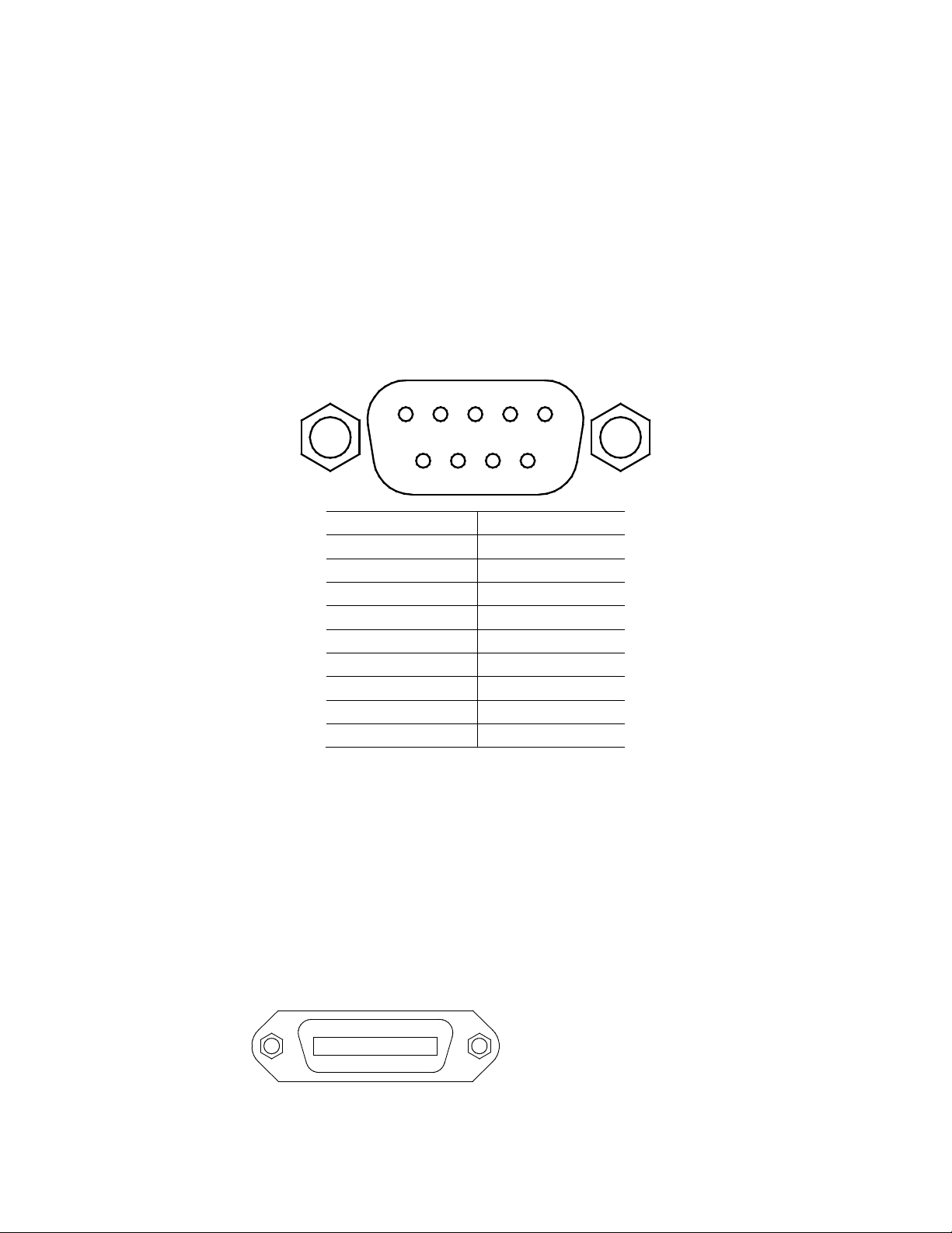
PIN
Description
1
-
2
Transmit Data
3
Receive Data
4
-
5
GND
6 - 7 - 8
-
9
-
1 2 3 4 5 6 7 8 9
1 Remote Operation
1.1 Interface Connection
RS-232
For RS-232 connectivity, refer to the diagram below for pin out information. The RS-232 is
labeled in the rear panel and it is a female DB-9 interface.
A straight pin-to-pin DB9 female to DB9 male serial cable is required for using the RS-232
interface. Do not use a null modem or crossover DB9 serial cable.
Refer to the user manual for details on configuring all serial settings as required for RS-232
communication.
GPIB
The power supply can be configured with a GPIB address from 0 – 31. To communicate via GPIB,
connect a GPIB cable to the GPIB interface on the rear panel, as illustrated below.
Page 5
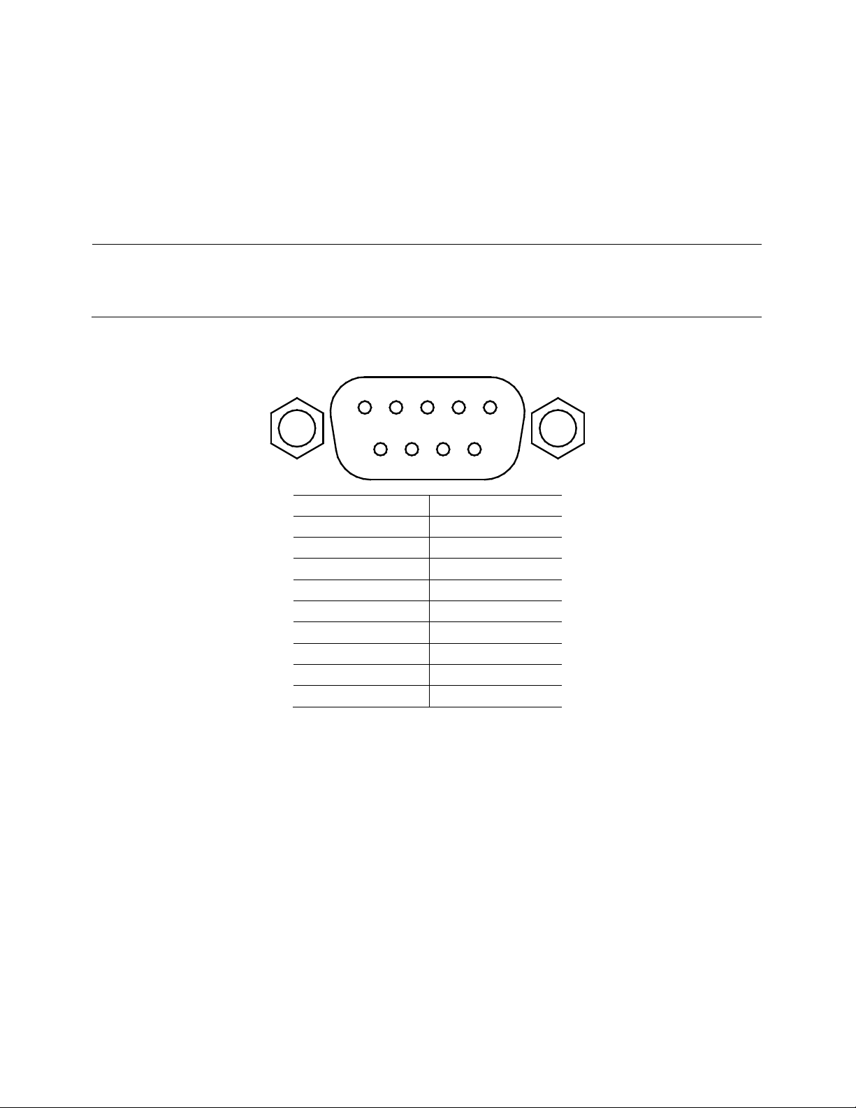
Note: Pin 1 is used as the B pin (+) (non-inverting).
SC (reference) pin is not used.
PIN
Description
1
B (+)
2 - 3 - 4 - 5
A (-)
6
-
7 - 8 - 9
-
1 2 3 4 5
6
7 8 9
RS-485
For multi-unit configuration and control, the male DB-9 interface labeled RS-485 in the rear
panel is used. The below illustrates the connection pins and description.
Pin 5 is used as the A pin (-) (inverting).
USBTMC
The device is SR1, RL1, and DT1 enabled. It can receive the following request:
REN_CONTROL, GO_TO_LOCAL, LOCAL_LOCKOUT. When it receives MsgID = TRIGGER USBTMC
command, it will transmit TRIGGER command to the function layer.
Page 6

Bit
Position
7 6 5 4 3 2 1
0
Bit Name
PON
Not
used
CME
EXE
DDE
QYE
Not
used
OPC
Bit Weight
128 32
16 8 4 1
2 Remote Commands
2.1 IEEE488.2 Common Commands
Here’s a list and description of all common SCPI commands supported by the instrument.
*CLS
This command clears the following registers.
Standard event register
Query event register
Operation event register
Status byte register
Error code
Command syntax: *CLS
Parameter: None
*ESE
This command can set the parameter of standard event enable register. Setting parameter can
determine which bit of standard event register is 1 and the byte will enable ESB of status byte
register as 1.
Command syntax: *ESE <NR1>
Parameter: 0~255
The value when power on: Refer to *PSC command
Example: *ESE 128
Query syntax: *ESE?
Returned parameter: <NR1>
The bit definition of the standard event enabled register:
PON Power-on
CME Command error
EXE Execution error
DDE Device-dependent error
QYE Query error
OPC Operation complete
Page 7

*ESR?
This command can read the value of standard event status register. After executing this
command, standard event status register is reset. Bit definition of standard event status register
is the same as the standard event status enable register.
Query syntax: *ESR?
Parameter: None
Returned parameter: <NR1>
*IDN?
This command can read information about power supply. The returns parameter contains 4
segments divided by comma.
Query syntax: *IDN?
Parameter: None
Returned parameter: <AARD> segment description
B&K Precision Manufacturer
9115 Product model
XXXXXX Product serial number
VX.XX –VX.XX Software version
Example: B&K Precision, 9115, 00000000000004, V1.01-V1.00
*OPC
When all commands before this command are executed, bit OPC in standard event register will
be set to 1.
Command syntax: *OPC
Parameter: None
Query syntax: *OPC?
Returned parameter: <NR1>
*RST
This command resets the power supply to default settings.
Command syntax: *RST
Parameter: None
*SRE
This command can set the parameter of state byte enable register. Setting parameter can
determine which byte value of state byte register is 1 and the byte will set RQS of state byte
register to 1. Bit definition of state byte enable register is the same as the state byte register.
Command syntax: *SRE <NR1>
Parameter: 0~255
Query syntax: *SRE?
Returned parameter: <NR1>
*STB?
This command can read the data from status byte register.
Page 8

BIT
Signal
Meaning
5
CC
Operation status register
The power supply is in constant current status.
0
OV
Query status register
Over voltage
Query syntax: *STB?
Parameter: None
Returned parameter: <NR1>
*TRG
When power supply trigger source is a command from via BUS, this command will give a trigger
signal. And its function is the same as “TRIGger” command.
Query syntax: *TRG
Parameter: None
Returned parameter: None
*SAV
This command can save the current setups of power supply to specified memory. These setups
contain current setups, voltage setups, max voltage set, min voltage set, OVP set, OVP timer,
OPP set, voltage rise and fall time, analog interface and series/parallel setting.
The memory is divided into 10 groups, each contain 0~9 (10 total) setups. Up to 100 setups can
be saved in total.
Command syntax: *SAV<NRf>
Parameter: 0~9
*RCL
This command can recall the setups you saved previously from the specified memory location.
Command syntax: *RCL<NRf>
Parameter: 0~9
2.2 STATUS Subsystem
You can get the current status of the power supply by reading the operation status registers. The
power supply records the different status of the instrument through the four status register
group. The four status register groups are: status byte register, standard event register, query
status register and operation status register. Status byte register records the information of the
other status registers.
0
3
4
CAL
WTG
CV
The power supply is calculating the new calibration parameter.
The power supply is waiting for the trigger information.
The power supply is in constant voltage status.
Page 9

1
4
OC
OT
Over current
Over temperature
7
PON
Standard event register
7
OPER
Status byte register
If the status of enabled operation register changes, then this bit is set to1.
Bit
Position
15
14
13
12
11
10 9 8
Bit Name
Not
used
Not
used
Not
used
Not
used
Not
used
Not
used
Not
used
Not
used
Bit Weight
Bit
Position
7 6 5 4 3 2 1
0
Bit Name
Not
used
Not
used
Not
used
OT
OP
Not
used
OC
OV
Bit Weight
16 8 2 1
3
0
2
3
4
5
2
3
4
5
6
STATUS Subsystem
STATus:QUEStionable[:EVENt]?
This command can be used to read the value in query event register. After executing this
command, the query event register will be cleared.
Query syntax: STATus:QUEStionable[:EVENt]?
Parameter: None
Returned parameter: <NR2>
Relative command: STATus:QUEStionable:ENABle
The bit definition of query event enable register:
OP
OPC
QYE
DDE
EXE
CME
EAV
QUES
MAV
ESB
RQS
Over power
Operation completed. All the parallel operations are completed.
Query error. Output buffer data lost.
Instrument memory data loss or self test error
Execute error. Command parameter over flow or the operation condition is
not consistent
Command error. There is syntax or semantic error in the command received.
Power on bit, this bit is set to 1 after power on
Error buffer available
This bit is set to 1 when any one status of enabled query status register
changes.
Output buffer available
Bit ESB is set to 1 when the status of a enabled standard event status register
changes
Page 10

STATus:QUEStionable:CONDition?
This command is used to read the value of query condition register. When a bit of QUES
condition changes, the bit value corresponding in QUEST event register is 1.
Query syntax:STATus:QUEStionable: CONDition?
Parameter: None
Returned parameter: <NR2>
STATus:QUEStionable:ENABle
This command can set the parameter of quest event enable register. Setting parameter can
determine which bit value of quest event register is 1 and the bit will enable QUES.
Command syntax:STATus:QUEStionable:ENABle <NR2>
Parameter: 0~65535
Default set: Refer to *PSC command
Example: STATus:QUEStionable:ENABle 128
Query syntax: STATus:QUEStionable:ENABle?
Returned parameter: <NR2>
STATus: QUEStionable:NTRansition
This command is used to edit the negative transition trigger register of operation event. The
parameter determines which bits of operation event register is 1 and will change the OPER of
status byte register to be 1.
Command syntax: STATus: QUEStionable:NTRansition <NR1>
Parameter: 0~255
Example: STATus: QUEStionable:NTRansition 128
Query syntax: STATus: QUEStionable:NTRansition?
STATus: QUEStionable:PTRansition
This command is used to edit the positive transition trigger register of operation event. The
parameter determines which bits of operation event register is 1 and will change the OPER of
status byte register to be 1.
Command syntax: STATus: QUEStionable:PTRansition <NR1>
Parameter: 0~255
Example: STATus: QUEStionable:PTRansition 128
Query syntax: STATus: QUEStionable:PTRansition?
STATus:OPERation[:EVENt]?
This command can read the parameter from operation event register. After executing this order,
operation event register is reset.
Query syntax: STATus:OPERation [:EVENt]?
Parameter: None
Returned parameter: <NR1>
Relative command: STATus: OPERation:ENABle
Bit definition of operation event register:
Page 11

Bit
Position
7 6 5 4 3 2 1
0
Bit Name
Not
used
Not
used
CV
CC
WTG
Not
used
Not
used
CAL
Bit
Weight
32
16 4 1
STATus:OPERation:CONDition?
This command can read the parameter from the operation condition register. When the
parameter of operation condition register changes, the bit corresponding in operation event
register is 1.
Query syntax: STATus: OPERation: CONDition?
Parameter: None
Returned parameter: <NR1>
STATus:OPERation:ENABle
This command can set the parameter of operation event enable register. Setting parameter can
determine which bit value of operation event register is 1 and the bit will change OPER of status
byte register to be 1.
Command syntax: STATus: OPERation:ENABle <NR1>
Parameter: 0~255
Example: STATus: OPERation:ENABle 128
Query syntax: STATus: OPERation:ENABle?
Returned parameter: <NR1>
STATus:OPERation:NTRansition
This command is used to edit the negative transition trigger register of operation event. The
parameter determines which bits in operation event register is 1 and will change the OPER bit
of status byte register to be set to 1.
Command syntax: STATus:OPERation:NTRansition <NR1>
Parameter: 0~255
Example: STATus:OPERation:NTRansition 128
Query syntax: STATus:OPERation:NTRansition?
STATus:OPERation:PTRansition
This command edits the positive transition trigger register of operation event. The parameter
determines which bits of operation event register is 1 and will change the OPER bit of status
byte register to be set to 1.
Command syntax: STATus:OPERation:PTRansition <NR1>
Parameter: 0~255
Example: STATus:OPERation:PTRansition 128
Query syntax: STATus:OPERation:PTRansition?
Page 12

2.3 SYSTEM Subsystem
SYSTem:ERRor?
This command is used to read the error code and the error information.
Command syntax: SYST:ERR?
Parameter: None
Returned parameter: <NR1>,<SRD>
The following is the error code and the definition:
(101) Too many numeric suffices
(110) No input command
(114) Invalid Numeric suffix
(116) Invalid value
(117) Invalid dimensions
(120) Parameter overflowed
(130) Wrong units for parameter
(140) Wrong type of parameter
(150) Wrong number of parameter
(160) Unmatched quotation mark
(165) Unmatched bracket
(170) Invalid command
(180) No entry in list
(190) Too many dimensions
(191) Too many char
(-200) Execution error
(-221) Settings conflict
(-222) Data out of range
(-223) Too much data
(-224) Illegal parameter value
(-225) Out of memory
(-230) Data Corrupt or Stale
(-270) Macro error
(-310) System error
(-350) Too many errors
(-400) Query error
(-410) Query INTERRUPTED
(-420) Query UNTERMINATED
(-430) Query DEADLOCKED
(-440) Query UNTERMINATED
(0) No error
(1) Module Initialization Lost
(2) Mainframe Initialization Lost
(3) Module Calibration Lost
Page 13

(4) Eeprom failure
(5) RST checksum failed
(10) RAM selftest failed
(40) Flash write failed
(41) Flash erase failed
(213) RS-232 buffer overrun
(216) RS-232 receiver framing
(217) RS-232 receiver parity
(218) RS-232 receiver overrun
(220) Front panel uart overrun
(221) Front panel uart framing
(222) Front panel uart parity
(223) Front panel buffer overrun
(224) Front panel timeout
(225) Front Crc Check error
(226) Front Cmd Error
(401) CAL switch prevents
(402) CAL password is incorrect
(403) CAL not enabled
(404) readback cal are incorrect
(405) programming cal are incorrect
(406) Incorrect sequence of cal
(600) FETCH of data was not acquired
(601) Measurement overrange
SYSTem:VERSion?
This command is used to query the current SCPI version. The returned parameter is a string
like”YYYY.V”, in which the YYYY is the year of that version, V is the software version of that year.
Command syntax: SYST:VERS?
Parameter: None
Returned parameter: <NRf>
SYSTem:REMote
This command is used to switch to the remote control mode (PC control).
Parameter: None
SYSTem:LOCal
This command is used to switch the instrument to local control mode (front panel control).
Command syntax: SYST:LOCal
Parameter: None
SYSTem:RWLock
This command is the same function as SYSTem:REMote, except this command can lock “LOCAL”
button as well. When this command is executed, the “Local” button will be disabled.
Page 14

Command syntax: SYSTem:RWLock
Parameter: None
SYSTem:POSetup
This command configures the power on state of the instrument.
Command syntax: SYSTem:POSetup RST|SAV0
Parameter: RST|SAV0
Returned parameter: None
Query syntax: SYSTem:POSetup?
SYSTem:POSetup?
Command syntax: SYSTem:POSetup?
Parameter: None
Returned parameter: RST|SAV0
SYSTem:CLEar
This command is used to clear the error codes and information.
Command syntax: SYSTem:CLEar
Parameter: None
Returned parameter: None
SYSTem:BEEPer
This command is used to enable or disable the beeper.
Command syntax: SYSTem:BEEPer
Command syntax: SYSTem:BEEPer<bool>
Parameters: 0|1|ON|OFF
Query syntax: SYSTem:BEEPer?
Returned value 0 corresponds to the off state of beeper.
Returned value 1 corresponding to the on state of beeper.
Return parameters:0|1
SYSTem:COMMunicate:GPIB:RDEVice:ADDRess
This command is used to set the GPIB address.
Command syntax:SYSTem:COMMunicate:GPIB:RDEVice:ADDRess <NR1>
Paramters: 0-31
inquiry syntax: SYSTem:COMMunicate:GPIB:RDEVice:ADDRess?
Return parameters: <NR1>
SYSTem:INTerface
This command is used to select the communication interfaces.
Command syntax:SYSTem:INTerface <GPIB|USB|RS232 |RS485>
ADDRess
Page 15

This command is used to set the slave machine’s address when communicating through RS485
interface.
Command syntax: ADDRess <NR1>
Parameters: 0-31
2.4 TRIGGER Subsystem
TRIGger[:IMMediate]
This command is used to create a trigger signal. It will give a trigger signal in BUS trigger source
mode. The function is the same as command *TRG.
Command syntax: TRIGger[:IMMediate]
Parameter: None
Related commands: *TRG
TRIGger:SOURce
This command is used to select the trigger source. Power supply can receive trigger signals
directly from front panel by pushing “Trigger” button or receive from a BUS trigger signal (usin
*TRG command).
Command syntax: TRIG:SOURce <mode>
Parameters: MANUAL |BUS
Query syntax: TRIGger:SOURce?
Return parameter: MANUAL |BUS
2.5 SOURCE Subsystem
[SOURce:]OUTPut[:STATe]
This command is used to control the output state of the power supply.
Command syntax: [SOURce:]OUTPut [:STATe] <bool>
Parameter: 0|1|ON|OFF
Query syntax: [SOURce:]OUTPut[:STATe]?
Return parameter: 0|1
[SOURce:]RISe[:LEVel]
This command is used to set the voltage rising time of the power supply.
Command syntax: [SOURce:]RISe[:LEVel] <NRf>
Unit: s
Parameter: 0~65.535
Query syntax: [SOURce:]RISe[:LEVel]?
Return parameter: 0~65.535
Page 16

[SOURce:]FALL[:LEVel]
This command is used to set the voltage falling time of the power supply.
Command syntax: [SOURce:] FALL [:LEVel] <NRf>
Unit: s
parameter: 0~65.535
Query syntax: [SOURce:] FALL [:LEVel]?
Return parameter: 0~65.535
[SOURce:]CURRent[:LEVel][:IMMediate][:AMPLitude]
This command is used to set the output current value.
Command syntax: [SOURce:]CURRent[:LEVel][:IMMediate][:AMPLitude] <NRf>
Parameter: MIN TO MAX|MIN|MAX|DEF
Unit: A |mA |uA
Query syntax: [SOURce:]CURRent[:LEVel][:IMMediate][:AMPLitude]?
Parameter: None
Return parameter: <NRf>
[SOURce:]CURRent[:LEVel]:TRIGgered[:AMPLitude]{<current level> | MINimum | MAXimum }
This command is used to set a current value to be triggered. This value will be set after the
instrument receives a trigger signal. Sending CURRent command will not impact this
command’s current setting value. Sending a query command will return the original setting
value.
Command syntax: [SOURce:]CURRent[:LEVel]:TRIGgered[:AMPLitude] <NRf>
Parameter: MIN TO MAX|MIN|MAX|DEF
Unit: A
Query syntax: [SOURce:]CURRent[:LEVel]:TRIGgered[:AMPLitude]?
Return parameter: <NRf>
[SOURce:]VOLTage[:LEVel][:IMMediate][:AMPLitude]
This command is used to set the output voltage value.
Command syntax: [SOURce:]VOLTage[:LEVel][:IMMediate][:AMPLitude] <NRf>
Parameters: MIN TO MAX|MIN|MAX|DEF
Unit: V| mV| uV
Query syntax: [SOURce:]VOLTage[:LEVel][:IMMediate][:AMPLitude]?
Parameter: None
Return parameter: <NRf>
[SOURce:]VOLTage[:LEVel]:TRIGgered[:AMPLitude]{<voltage level> |MINimum | MAXimum}
This command is used to set a voltage value to be triggered. This value will be set when the
instrument receives a trigger signal. Sending VOLTage command will not impact this command’s
voltage setting value. Sending a query command will return the original setting value.
Command syntax: [SOURce:]VOLTage[:LEVel]:TRIGgered[:AMPLitude] <NRf>
Parameters: MIN TO MAX|MIN|MAX|DEF
Page 17

Unit: V| mV| uV
Query syntax: [SOURce:]VOLTage[:LEVel]:TRIGgered[:AMPLitude]?
Return parameter: <NRf>
[SOURce:]VOLTage:PROTection[:LEVel]
This command is used to set the software-voltage protection value.
Command syntax: [SOURce:] VOLTage:PROTection[:LEVel] <NRf>
Parameter: MIN TO MAX|MIN|MAX|DEF
Parameters: V |mV| uV
Query syntax: [SOURce:] VOLTage:PROTection[:LEVel]?
Parameters: None
Return parameter: <NRf>
[SOURce:]VOLTage:PROTection:DELay
This command is used to set the software-voltage protection delay time.
Command syntax: [SOURce:]VOLTage:PROTection:DELay<NRf>
Parameter: 0.001~0.6
unit: s
Query syntax: [SOURce:]VOLTage:PROTection:DELay?
Parameter: 0.001~0.6
Return parameter:<NRf>
[SOURce:]VOLTage:PROTection:STATe
This command is used to set the software-voltage protection state.
Command syntax: [SOURce:]VOLTage:PROTection:STATe<bool>
Parameter: 0|1|ON|OFF
Query syntax: [SOURce:]VOLTage:PROTection:STATe?
Parameter: None
Return parameter: 0|1
[SOURce:]VOLTage:PROTection:TRIGgered?
This command is used to query the executing state of over voltage protection. If “1 ”, this
indicates the OVP circuit has been triggered and the OVP state is not cleared. If “0 ”, the OVP
circuit is not triggered.
Command syntax: [SOURce:]VOLTage:PROTection:TRIGgered?
Return value: 0|1
PROTection:CLEar
This command is used to clear the OVP state. Before sending this command, please increase
the upper limitation of OVP or reeeduce the output voltage.
Note: Please remove the device that tripped this protection and then send the command again.
Command syntax: PROT:CLE
[SOURce:]VOLTage:LIMit[:LEVel]<voltage>
Page 18

This command is used to set the lower limitation of the output voltage.
Command syntax: [SOURce:]VOLTage:LIMit[:LEVel] <NRf>
Parameter: MIN TO MAX|MIN|MAX|DEF
Unit: V| mV| uV
Query syntax: [SOURce:]VOLTage:LIMit[:LEVel]?
Return parameter: <NRf>
[SOURce:]VOLTage:RANGe<voltage>
This command is used to set the upper limitation of the output voltage.
Command syntax: [SOURce:]VOLTage:RANGe <NRf>
Parameter: MIN TO MAX|MIN|MAX|DEF
Unit: V |mV |uV
Query syntax: [SOURce:]VOLTage:RANGe?
Return parameter: <NRf>
[SOURce:]APPLy {<voltage>|MIN|MAX} [,{<current> |MIN|MAX}]
This command combines two commands in one: VOLTage , CURRent. As long as the setting
value is within the range of max current and max voltage, then the output voltage and current
will execute according to the present setting value. APPLy command will only be effective when
the setting values are within the range of the upper limits. If not, an execution error will occur.
MIN and MAX can also be used as parameters. Min will enable the output voltage and current
to be 0. Max will enable the output voltage and current to be the upper limit value.
Command syntax: [SOURce:]APPLy <NRf>,<NRf>
Parameter: MIN~MAX
Unit: V, A
Query syntax: [SOURce:]APPLy?
Return parameter: <NRf>,<NRf>
2.6 MEASUREMENT Commands
MEASure[:SCALar]:VOLTage[:DC]?
This command is used to query the actual output voltage.
Command syntax: MEASure[:SCALar]:VOLTage[:DC]?
Parameter: None
Return parameter: <NRf>
Return parameter unit: V
Example: MEAS:VOLT?
FETCh:VOLTage?
This command is used to read the voltage to be handled in the sample cache. After sending the
command, the readings will be sent to the computer. This command does not affect the
instrument settings. This command does not trigger a measurement operation, and queries
only the latest available reading. Before reading the new reading, the command returns old
Page 19

readings.
Command syntax: FETCh:VOLTage?
Return parameter: <NRf>
Return parameter unit: V
MEASure[:SCALar]:CURRent[:DC]?
This command is used to read the actual current.
Command syntax: MEASure[:SCALar]:CURRent[:DC]?
Parameter: None
Return parameter: <NRf>
Return parameter unit: A
example: MEAS:CURR?
FETCh:CURRent?
This command is used to read the current which is in the sample cache. After sending the
command, the readings will be sent to the computer. This command does not affect the
instrument settings. This command does not trigger a measurement operation, and queries
only the latest available reading. Before reading the new reading, the command returns the old
readings.
Command syntax: FETCh:CURRent?
Return parameter: <NRf>
MEASure[:SCALar]:POWer[:DC]?
This command is used to enquire the actual output power.
Command syntax: MEASure[:SCALar]:POWer[:DC]?
Parameter: None
Return parameter: <NRf>
Return parameter unit: W
Example: MEAS:POWer?
FETCh:POWer?
This command is used to read the power which is in the sample cache. After sending the
command, the readings will be sent to the computer. This command does not affect the
instrument settings. This command does not trigger a measurement operation, and queries
only the latest available reading. Before reading the new reading, the command returns the old
readings.
Command syntax: FETCh:POWer?
Return parameter: <NRf>
Page 20

2.7 LIST AND SEQUENCE Commands
LIST Commands
LIST:STATe
This command is used to set the state of list mode.
Command syntax: LIST:STATe <0|1|ON|OFF>
Query syntax: LIST:STATe?
Return parameter: 0|1
LIST:RECall
This command is used to recall a list file.
Command syntax: LIST:RECall <NR1>
Parameter: 1~10
Query syntax: LIST:RECall?
Return parameter: 1~10
LIST:EDIT
This command is used to select which list file to edit.
Command syntax: LIST:EDIT <NR1>
Parameter: 1~10
Query syntax: LIST:EDIT?
Return parameter: 1~10
LIST:POWer
This command is used to edit the power limit of the list file.
Comman syntax:LIST:POWer <NRf>
Parameter: MIN~MAX
Query syntax: LIST:POWer?
Return parameter: MIN~MAX
LIST:REPeat
This command is used to edit the number of repeat times of the list file.
Command syntax:LIST:REPeat <NR2>
Parameter: 1~65535
Query syntax: LIST:REPeat?
Return parameter: 1~65535
LIST:LINK:SEQuence
This command is used to edit the list sequence to be linked.
Command syntax: LIST:LINK:SEQuence <NR2>
Parameter: 0~1023
Page 21

Query syntax: LIST:LINK:SEQuence?
Return parameter: 0~1023
LIST:SEQuence:REPeat <NR1>,<NR1>
This command is used to edit the running count of sequence which is linked to the List file.
Command syntax: LIST:SEQuence:REPeat<NR1>,<NR1>
Parameter: Parameter1 represents the sequence number,parameter2 corresponds to the
running count of the sequence (1~65535).
Query syntax: LIST:SEQuence:REPeat? <NR2>
Return parameter: 0~65535
LIST:SAVe
This command is used to save the list file in nonvolatile memory.
Command syntax: LIST:SAVe
Parameter: None
SEQUENCE Commands
SEQuence:EDIT
This command is used to select the list sequence to be edited.
Command syntax: SEQuence:EDIT <NR1>
Parameter: 1~10
Query syntax: SEQuence:EDIT?
Return parameter: 1~10
SEQuence:STEP:ACTive
This command is used to select the steps to be activated of sequence.
Command syntax: SEQuence:STEP:ACTive <NR2>
Parameter: 0~1023
Query syntax: SEQuence:STEP:ACTive?
Return parameter: 0~1023
SEQuence:VOLTage
This command is used to edit the voltage of specified step of the sequence.
Command syntax: SEQuence:VOLTage <NR1>,<NRf>
Unit: V
parameter: Parameter1 represents the number of step to be edited. Parameter2 is the voltage
(MIN~MAX).
Query syntax: SEQuence:VOLTage? <NR1>
Return parameter: MIN~MAX
SEQuence:CURRent
This command is used to edit the current of specified step of a sequence file.
Command syntax: SEQuence:CURRent<NR1>,<NRf>
Page 22

Parameter: Parameter1 represents the number of step to be edited.Parameter2 is the current
(MIN~MAX).
Query syntax: SEQuence:CURRent? <NR1>
Return parameter: MIN~MAX
SEQuence:WIDTh
This command is used to edit the width of specified step of the sequence file .
Command syntax: SEQuence:WIDTh <NR1><,NRf>
Parameter: Parameter1 represents the number of steps to be edited.Parameter2 is the time
width (0.001~65.535).
Unit: s
Query syntax: SEQuence: WIDTh? <NR1>
Return parameter: 0.001~65.535
SEQuence:SLOPe
This command is used to edit the slope of a specified step of the sequence file
Command syntax:SEQuence:SLOPe <NR1>,<NRf>
parameter: Parameter1 represents the number of steps to be edited.Parameter2 is the
slope(0.001~65.535).
unit: s
Query syntax: SEQuence:SLOPe? <NR1>
Return parameter: 0.001~65.535
SEQuence:SAVe
This command is used to save the sequence file.
Command syntax: SEQuence:SAVe
Parameter:None
Page 23

22820 Savi Ranch Parkway
Yorba Linda, CA92887
www.bkprecision.com
© 2013, 2014 B&K Precision Corp.
V020414
 Loading...