

Page 1

INSTRUCTION
MANUAL
Model 9110
Model 9110
100W Multi Range 60V/5A DC Power Supply
Page 2

WARNING
Safety Regulations
To avoid electrical shock, do not open the cabinet. Refer servicing to
qualified personnel only.
To avoid injuries, always disconnect power, discharge circuits, and
remove external voltage sources before touching components.
KEEP AWAY FROM LIVE CIRCUITS.
We cannot accept responsibility for any direct or indirect financial
damage or loss of profit that might occur when using the power supply.
The instrument chassis and cover must be connected to an electrical
ground.
Compliance Statements
Disposal of Old Electrical & Electronic Equipment (Applicable in the European
Union and other European countries with separate collection systems)
This product is subject to Directive 2002/96/EC of the European
Parliament and the Council of the European Union on waste
electrical and electronic equipment (WEEE) , and in jurisdictions
adopting that Directive, is marked as being put on the market after
August 13, 2005, and should not be disposed of as unsorted
municipal waste. Please utilize your local WEEE collection
facilities in the disposition of this product and otherwise observe all
applicable requirements.
Safety Symbols
Protective Ground (Earth terminal)
Page 3
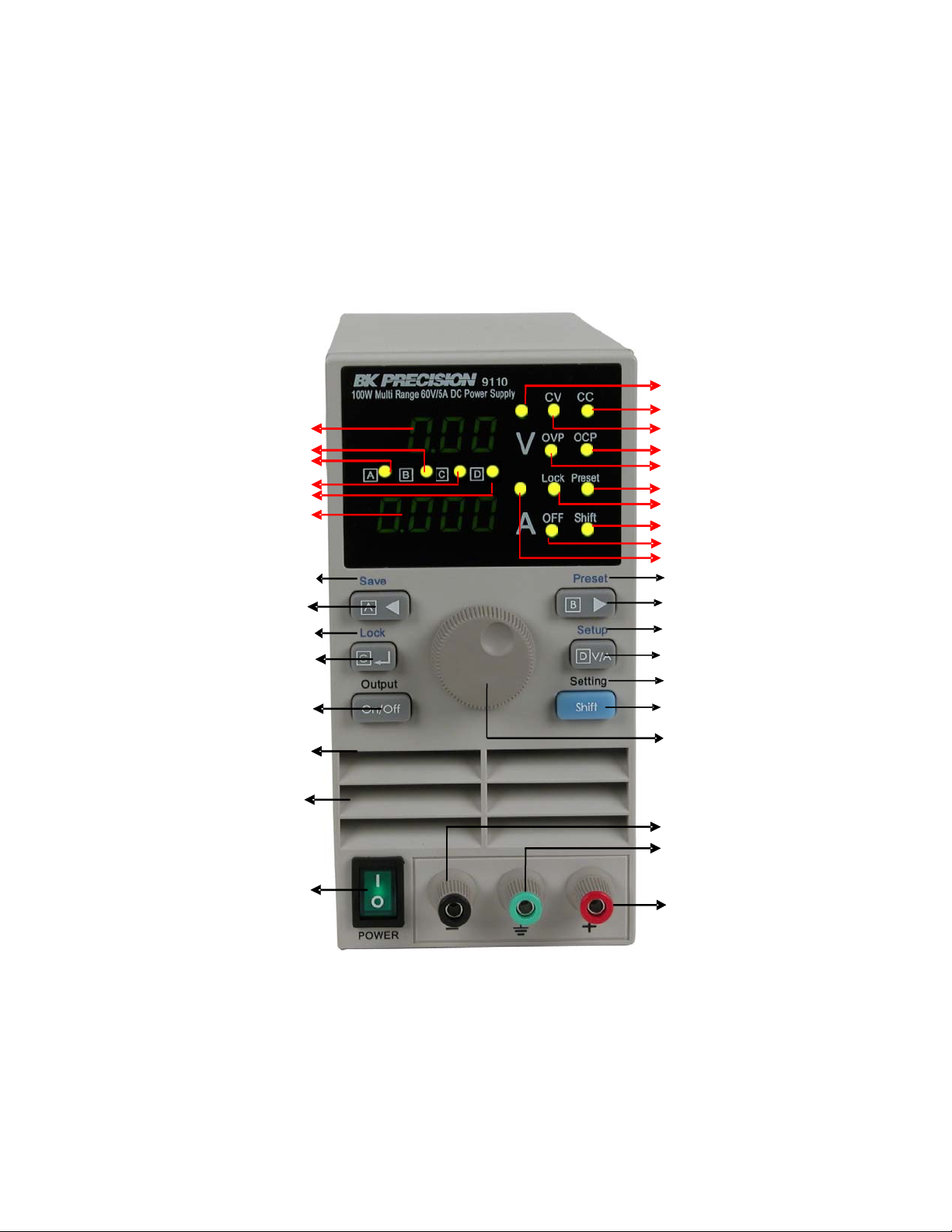
Front Panel layout
Voltage value
Cursor position B or preset B is active
Cursor position A or preset A is active
Cursor position C or preset C is active
Cursor position D or preset D is active
Current value
Current value
Store voltage-ampere combination (Shift)
Move cursor left or store/recall
preset A values
Keyboard lock (Shift)
Enter or store/recall preset C values
Output on/off
Set Voltage indicator
CC mode indicator
CV mode indicator
OCP indicator
OCP indicator
OVP indicator
OVP indicator
Preset mode indicator
Keys locked indicator
Shift mode indicator
Output off indicator
Set Current indicator
Recall Preset values
Move cursor left or store/recall
preset B values
Enter OVP, OCP, preset mode
Toggle between Voltage/Current
setting or store/recall preset D
Display Voltage and Current setting
Secondary function key
Air flow input
Main power on/off
knob
Output Ground
Output +
Page 4
Introduction
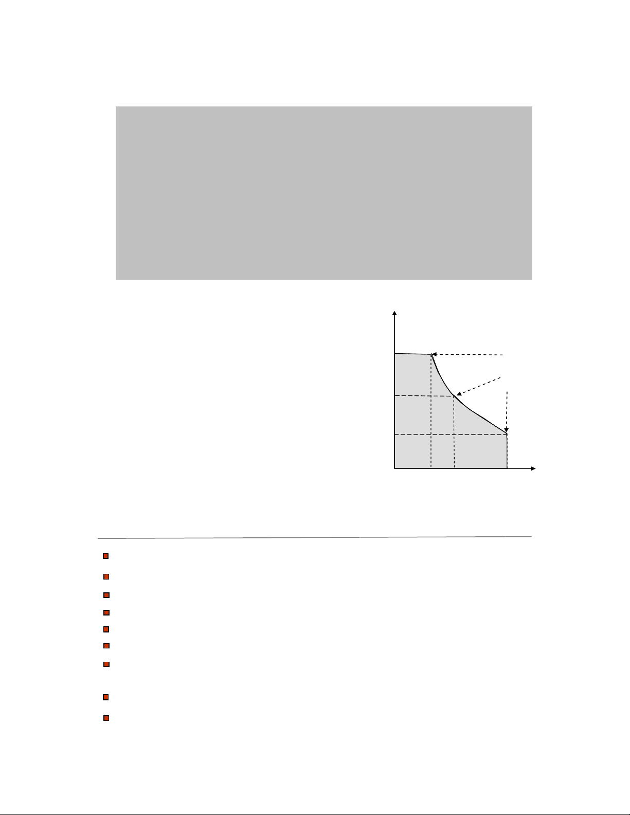
The 9110 is a new type of power supply. Unlike conventional
power supplies with fixed output ratings, the 9110 automatically
recalculates voltage/current limits for each setting, forming a
constant power hyperbolic shaped boundary as illustrated in the
diagram below. Any Volt/Amp combination that doesn’t exceed
100W, 60V or 5A can be set. By providing greatly expanded
choices of maximum power volt-ampere combinations, users can
cut down on the number of power supplies required and free up
valuable bench space.
Example:
When setting the voltage to the maximum
value of 60V, the max. current value is
100W / 60V = 1.66A. For a 10V setting,
the max current is limited to 5A, in which
case the maximum output power is only
50W.
A maximum output power of 100W is
possible for all V/A combination that lie on
the hyperbolic curve.
Features
Digitally controlled, mixed linear/switching mode DC p
10mV/1mA resolution over the full range
Bright, easy to read display
Low ripple and noise
V
60
40
20
1
2345
ower supply
Power
100%
I
Very compact size and light weight
Output ON/OFF Control
High reliability due to OVP, OCP and OTP (over voltage, over
current, over temperature) protection
CV (Constant Voltage) and CC (Constant Current) operation
Store/Recall 100 groups with 4 sets of Volt/Amp memories each
Page 5

Installation
Unpacking the instrument
This instrument was carefully inspected before shipment. Upon receipt,
inspect the instrument for damage that might have occurred in transit. If any
sign of damage is found, notify your B+K Precision distributor.
Check the list of supplied items
Verify that you have received the following items with your power supply. If
anything is missing, contact your authorized B+K Precision distributor.
- Power cord
- Instruction manual
Power Requirements
The 9110 can operate on 110V AC or 220V AC. Before connecting the power
cord to an AC outlet, make sure the voltage selector in the rear is set to the
correct line voltage.
If necessary, replace fuses according to this table.
FuseRangeLine voltage
T0 3.15A, 250V99V to 121V110V AC
T0 2.5A, 250V198V to 242V220V AC
The instrument power fuse is located in a fuse compartment below the AC
input receptacle. To access the fuse, first disconnect the power cord and then
remove the fuse cartridge.
Power-on procedure
Turn on the instrument by pressing the main power switch on the front panel
of the unit. The instrument will automatically revert to the last setting before
the power was turned off.
Note
The 9 pin D-sub connector in the rear is for factory use only!
This instrument does not offer a remote control interface.
Page 6

Quick Start
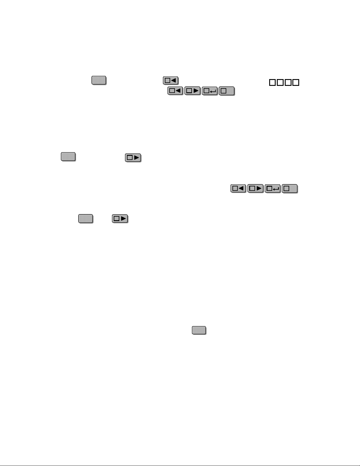
Set Voltage
D
Press the key to turn the “V”
V/ADV/A
indicator on. Now you can set the voltage
AA
value. Use the cursor keys
BB
to highlight the desired digit then adjust
its value with the knob.
In this example the cursor is set to
position and the voltage value can be
B
adjusted in 1V increments.
Set Current
D
Press the key to turn on the “A”
indicator. Now you can set the current
value. Use cursors
to highlight the desired digit then adjust
its value with the knob.
In this example the cursor is set to
position and the current value can be
adjusted in 1A increments.
V/ADV/A
AA
BB
A
Set Voltage
100W Multi Range 60V/5A DC Power Supply
A
100W Multi Range 60V/5A DC Power Supply
A
B
B
C
cursor in B position
C
9110
D
9110
D
V
A
V
A
CV CC
OVP OCP
Lock
Preset
OFF
Shift
CV CC
OVP OCP
Lock
Preset
OFF
Shift
Turn output On/Off
On/OffOn/Off
Press to toggle the output between
ON or OFF. The OFF LED is lit when
the output is turned off. Each time you
press the key, the display will blink
for 3 seconds and the set value for Volts
and Amps is displayed. Afterwards, if
the instrument has been set to ON, the
actual output values for voltage and
current are displayed.
On/OffOn/Off
cursor in A position
100W Multi Range 60V/5A DC Power Supply
A
B
Set Current
9110
CV CC
OVP OCP
V
C
D
Lock
OFF
Preset
Shift
A
Output OFF Indicator
Page 7

Cursor Position and Step Size
Cursor position
A
B
C
D
Voltage step size
1V
0.1V
0.01V
Current step size
1A
0.1A
0.01A
0.001A
Check the Set Voltage and Set Current Value
The power supply usually displays the actual voltage and current value. Press
twice to check the set value for voltage and current. The display will blink for 3
seconds while displaying the set values.
ShiftShift
Key Lock Function
This function locks the keyboard to prevent unintended modification of power
supply settings. Press (Shift LED will be lit), followed by the (Lock)
ShiftShift
CC
key. Now the keys and the knob are locked and the Lock LED is lit. Press the
Shift key followed by the Lock key again to disable the Lock function.
OVP Function
Press then press and hold the
ShiftShift
D
V/ADV/A
(Setup) key for 3 seconds.
Afterwards the LCD will display OVP
100W Multi Range 60V/5A DC Power Supply
9110
OVP OCP
V
and you can adjust the OVP value using
BB
the cursor keys and the
AA
A
B
C
D
Lock
CV CC
Preset
knob.
OCP Function
After the OVP value is set, press to
enter OCP mode. Use the cursor keys
BB
AA
and the knob to set the
OCP value.
CC
Note
The output of the power supply will
automatically turn off if the OVP and
OCP value are less than the actual
voltage and current value. Default
setting are OVP=61V and OCP=5.1A.
OVP Value
100W Multi Range 60V/5A DC Power Supply
A
B
OCP Value
C
9110
D
A
V
A
OFF
Shift
CV CC
OVP OCP
Lock
Preset
OFF
Shift
Page 8

Key sound
Once the OCP value is set, press
to enter the BEEP mode. Use the knob
to turn the key sound ON or OFF.
Press to confirm.
CC
9110
9110
100W Multi Range 60V/5A DC Power Supply
CC
100W Multi Range 60V/5A DC Power Supply
A
A
B
B
C
C
D
D
V
V
A
A
CV CC
CV CC
OVP OCP
OVP OCP
Lock
Lock
Prog
Prog
OFF
OFF
Shift
Shift
Set address
Press twice to skip the address
menu and advance to the group menu.
Note:
can be ignored.
Selecting a Group Number
To enter this mode, you have to step
through the previous 4 modes first. From
address mode, press to enter group
mode. Use the cursors and
the knob to select a group number.
There are 100 groups, each group can store
4 sets of voltage/current values. Press
to confirm the entry of the selected group
CC
This setting is for factory use only and
CC
AA
BB
CC
100W Multi Range 60V/5A DC Power Supply
A
A
B
100W Multi Range 60V/5A DC Power Supply
B
C
C
D
D
9110
9110
V
A
V
A
CV CC
OVP OCP
Lock
Prog
OFF
Shift
CV CC
OVP OCP
Lock
Preset
OFF
Shift
number.
Page 9
Storing Voltage/Current sets
Store up to four sets of voltage/current values to the group number assigned in the previous
paragraph. Press followed by the (Save) key. All 4 cursor LEDs
ShiftShift
will blink simultaneously. Press one of the
AA
AA
BB
CC
D
V/ADV/A
BA
C
D
keys to assign one of the 4 available memory location within this group. Proceed
accordingly for the other 3 sets.
Preset Mode
Press followed by the (Preset) key. The Preset LED will turn on to indicate
ShiftShift
BB
that the Preset mode is now active. The most recently selected group number will
automatically be activated. To activate the preset values from a different group, follow
AA
BB
the instructions in “Selecting a group number”. Press one of the
CC
keys to recall one of the corresponding stored Volt/Amp sets assigned in the previous
step. In this mode, the cursor functionality of the A,B,C, D keys is disabled. To exit this
mode, press then (Preset).
ShiftShift
BB
Trouble shooting hints
If the output is disabled
1. Check if the voltage and current values are zero. If set to zero, set the voltage and
current value again.
2. Check if the OFF indicator is lit. If so, press the key to turn the output on.
3. Check if the OCP or OVP indicator is lit. If so, set the OVP or OCP value
appropriately.
On/OffOn/Off
D
V/ADV/A
If keys are disabled
Check the Lock LED. If it is lit, disable the Lock function.
Page 10

Specification
Model 9110
Output Rating Voltage
Current
Power 100 W
Load Regulation
Line Regulation
Setting Accuracy Voltage
Display Accuracy
Ripple
Dimension (mm)
Voltage
Current
Voltage
Current
Current
Voltage
Current
Voltage
Current
WxHxD
0~60 V
0~5 A
<0.01 %+3 mV
<0.01 %+3 mA
<0.01 %+3 mV
<0.1 %+3 mA
<0.05 %+10 mV
<0.2 %+2 mA
<0.05 %+10 mV
<0.1 %+2 mA
<2.0 mVrms
<5 mArms
3.47” x 6.9” x 11.11”
88 mm x 175 mm x 282 mm
Weight
Specifications and information are subject to change without notice.
Please visit www.bkprecision.com
information.
Net
5.9 lbs (2.65 Kg )
for the most current product
Page 11

Warranty
Service Information
Warranty Service: Please return the product in the original packaging with proof of purchase to the
address below. Clearly state in writing the performance problem and return any leads, probes,
connectors and accessories that you are using with the device.
Non-Warranty Service: Return the product in the original packaging to the address below. Clearly
state in writing the performance problem and return any leads, probes, connectors and accessories
that you are using with the device. Customers not on open account must include payment in the
form of a money order or credit card. For the most current repair charges please visit
www.bkprecision.com
Return all merchandise to B&K Precision Corp. with pre-paid shipping. The flat-rate repair charge
for Non-Warranty Service does not include return shipping. Return shipping to locations in North
American is included for Warranty Service. For overnight shipments and non-North American
shipping fees please contact B&K Precision Corp.
Include with the returned instrument your complete return shipping address, contact name,
phone number and description of problem.
and click on “service/repair”.
B&K Precision Corp.
22820 Savi Ranch Parkway
Yorba Linda, CA 92887
www.bkprecision.com
714-921-9095
Limited One-Year Warranty
B&K Precision Corp. warrants to the original purchaser that its products and the component parts
thereof, will be free from defects in workmanship and materials for a period of one year fro m date
of purchase.
B&K Precision Corp. will, without charge, repair or replace, at its option, defective product or
component parts. Returned product must be accompanied by proof of the purchase date in the form
of a sales receipt.
To obtain warranty coverage in the U.S.A., this product must be registered by completing a
warranty registration form on www.bkprecision.com
Exclusions: This warranty does not apply in the event of misuse or abuse of the product or as a
result of unauthorized alterations or repairs. The warranty is void if the serial number is
altered, defaced or removed.
B&K Precision Corp. shall not be liable for any consequential damages, including without limitation
damages resulting from loss of use. Some states do not allow limitations of incidental or
consequential damages. So the above limitation or exclusion may not apply to you.
This warranty gives you specific rights and you may have other rights, which vary from state-tostate.
B&K Precision Corp.
22820 Savi Ranch Parkway
Yorba Linda, CA 92887
www.bkprecision.com
714-921-9095
within fifteen (15) days of purchase.
Page 12

22820 Savi Ranch Parkway
Yorba Linda, CA 92887
www.bkprecision.com
© 2007 B&K Precision Corp.
Printed in China Edition 1.21
 Loading...