

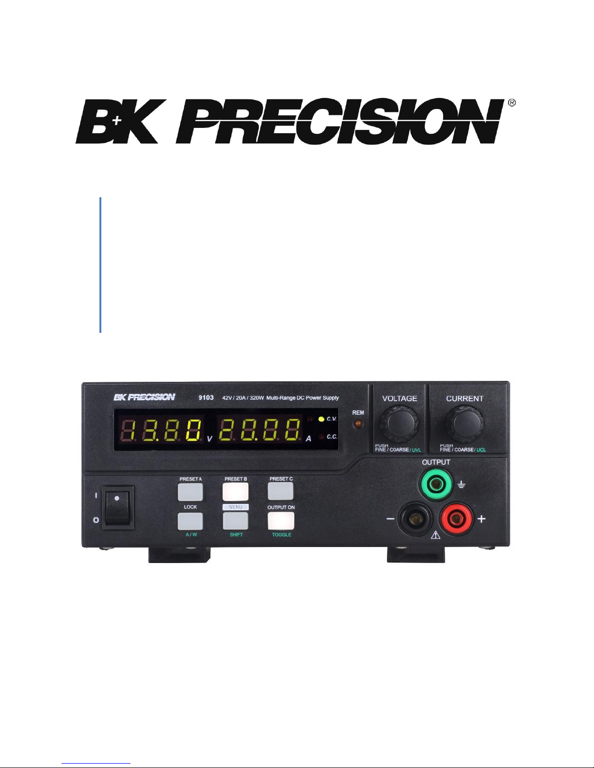
Model: 9103, 9104
Switching DC Power Supplies
PROGRAMMING MANUAL
Test Equipment Depot - 800.517.8431 - 99 Washington Street Melrose, MA 02176
TestEquipmentDepot.com

Table of Contents
1. USB Interface Connection ........................................................................................................ 3
Connecting Instrument to PC ...................................................................................................... 3
USB (Virtual COM) Configuration ............................................................................................... 3
2. Command Set .......................................................................................................................... 4
SOUT< Output > [CR] .................................................................................................................. 5
GOUT[CR] .................................................................................................................................... 5
VOLT< preset0/1/2/3><Voltage>[CR] ......................................................................................... 5
CURR< preset0/1/2/3><Current> [CR] ....................................................................................... 5
SOVP<voltage >[CR] .................................................................................................................... 5
GETD[CR] ..................................................................................................................................... 5
SOCP<Current>[CR] ..................................................................................................................... 5
GOVP[CR] .................................................................................................................................... 5
GOCP[CR] .................................................................................................................................... 5
SETD<preset0/1/2/3><VOLTAGE> .............................................................................................. 6
<CURRENT>[CR] .......................................................................................................................... 6
GETS<preset0/1/2/3>[CR] .......................................................................................................... 6
GABC[CR] ..................................................................................................................................... 6
SABC< preset0/1/2/3>[CR] ......................................................................................................... 6
GDLT<{0-5}>[CR] ......................................................................................................................... 6
SDLT <location {0-5}; time {00-20}>[CR] ..................................................................................... 6
GSWT<location {0-2}> ................................................................................................................. 6
SSWT<location {0-2} time {000-600}> [CR] ................................................................................. 6
RUNP< first {0-2}; end {0-2}>[CR] ............................................................................................... 6
STOP[CR] ..................................................................................................................................... 7
SESS[CR] ...................................................................................................................................... 7
ENDS[CR] ..................................................................................................................................... 7
GALL[CR] ...................................................................................................................................... 7
SETM ........................................................................................................................................... 8

1. USB Interface Connection
Users can remotely control the power supply via PC over the USB interface. Upon installation of
the USB driver, the PC can control the instrument over virtual COM.
Connecting Instrument to PC
a) Download the USB drivers from www.bkprecision.com .
b) Connect the included USB cable to the power supply and the USB port on the PC.
c) When Windows recognizes the USB connection, do not follow the default Windows driver
installation wizard. Simply run the setup file from the downloaded USB drivers and follow
the prompt to install drivers.
d) The computer will recognize the instrument as a USB (virtual COM) device, it will be
detected as a serial COM port. Windows will automatically assign a COM port to the
instrument. Please verify which COM port Windows has assigned by going into Device
Manager.
USB (Virtual COM) Configuration
The following serial port settings are used by the power supply.
Baudrate: 9600
Data bits: 8
Parity: None
Stop bits: 1
Flow Control: None

2. Command Set
In order to use remote commands, please make sure to use the following communication
settings:
1. Baud rate: 9600
2. Data bits: 8
3. Parity: none
4. Stop bits: 1
If you are using HyperTerminal, make sure to check your ASCII setup to not append line feeds.
Command line format: COMMAND<parameter1><parameter2>…[CR]
Test Equipment Depot - 800.517.8431 - 99 Washington Street Melrose, MA 02176
TestEquipmentDepot.com

#
Input Command and Return
Description
Example
1
SOUT< Output > [CR]
Return Value: [OK] [CR]
Set Output on/off.
Set Output off: < Output > =0
Set Output on: < Output > =1
Input Command: SOUT0[CR]
Return Value: [OK] [CR]
Result: Set Output off
2
GOUT[CR]
Return Value:<Output> [CR] [OK] [CR]
Get Output Status.
Output off: < Output > = 0
Output on: < Output > = 1
Input Command: GOUT [CR]
Return Value: 0 [CR] [OK] [CR]
Result: Output is off
3
VOLT< preset0/1/2/3><Voltage>[CR]
Return Value: [OK] [CR]
Set output Voltage.
*Set-Volt value relevance to preset Current
value total power<160W .Max-Volt value
refer to product specification
Input Command:
VOLT 01000[CR]
Return Value: [OK] [CR]
Result: Set Memory preset 1
voltage value is 10.00V
4
CURR< preset0/1/2/3><Current> [CR]
Return Value: [OK] [CR]
SET output Current.
* Set-Cur value relevance to preset Volt value
total power<160W .Max- Current value refer
to product specification
Input Command:
CURR 00100[CR]
Return Value: [OK] [CR]
Result: Set preset 1 Current
value is 1.00A
5
SOVP<voltage >[CR]
[Return Value:[OK] [CR]
Set Over Voltage value.
<voltage> = ????
Input Command: SOVP4200[CR]
Return Value: [OK] [CR]
Result: Set upper limit of output
Voltage 42.00V
6
GETD[CR]
Return Value: <Voltage ><Current>
<CV/CC Mode> [CR] [OK] [CR]
Get Reading Volt & Curr mode.
<voltage> = ????
< Current > = ????
<CV Mode> =0 CV Mode
<CV Mode> =1 CC Mode
Input Command: GETD [CR]
Return Value: 050001000[CR]
[OK] [CR]
Result: The Display value is
5.00V and 1.00A.
It is in CV mode.
7
SOCP<Current>[CR]
Return Value: [OK] [CR]
Set Over current value.
< Current > = ????
Input Command: SOCP1000[CR]
Return Value: [OK] [CR]
Result: Set upper limit of output
Current 10.00A
8
GOVP[CR]
Return Value: <Voltage>[CR] [OK] [CR]
Get upper limit of output Voltage.
<voltage>=????
Input Command: GOVP [CR]
Return Value: 4220 [CR] [OK]
[CR]
Result: upper limit of output
Voltage is 42.40V
9
GOCP[CR]
Return Value:<Current>[CR] [OK] [CR]
Get upper limit of output Current.
< Current >=????
Input Command: GAGA [CR]
Return Value: 1020 [CR] [OK]
[CR]
Result: upper limit of output
Current is 10.20A

10
SETD<preset0/1/2/3><VOLTAGE>
<CURRENT>[CR]
Return Value: [OK] [CR]
SET preset0/1/2/3 Voltage and Current.
<preset0/1/2/3> =0 preset1
<preset0/1/2/3> =1 preset2
<preset0/1/2/3> =2 preset3
<preset0/1/2/3> =3 Normal Mode
<voltage> = ????
< Current > = ????
Input Command:
SETD 005001000 [CR]
Return Value: [OK] [CR]
Result: Set preset1 voltage
5.00V Current 10.00A
11
GETS<preset0/1/2/3>[CR]
Return Value: <Voltage><Current>[CR]
[OK] [CR]
Get settings of preset0/1/2/3 Volt & Curr
SET preset0/1/2/3 Voltage and Current
<preset0/1/2/3> =0 preset1
<preset0/1/2/3> =1 preset2
<preset0/1/2/3> =2 preset3
<preset0/1/2/3> =3 Normal Mode
<voltage> = ????
< Current >=????
Input Command: GETS0[CR]
Return Value: 05000100[CR] [OK]
[CR]
Result: The Memory preset 1
voltage value is 5.00V and
Current is 1.00A.
12
GABC[CR]
Return Value: < preset0/1/2/3> [CR]
[OK] [CR]
Get preset selection
< preset0/1/2/3> =0 preset1
< preset0/1/2/3> =1 preset2
< preset0/1/2/3> =2 preset3
< preset0/1/2/3> =3 Normal Mode
Input Command: GABC [CR]
Return Value: 0 [CR] [OK] [CR]
Result: Preset Mode is Preset1
13
SABC< preset0/1/2/3>[CR]
Return Value: [OK] [CR]
Set ABC select
< preset0/1/2/3>=0 preset1
< preset0/1/2/3>=1 preset2
< preset0/1/2/3>=2 preset3
< preset0/1/2/3>=3 Normal Mode
Input Command: SABC 2[CR]
Return Value: [OK] [CR]
Result: Preset Mode is set to
Preset3
14
GDLT<{0-5}>[CR]
Return Value: delta time [00-20] [CR]
[OK] [CR]
Get delta time setting value
DeltaTime{0} : Time of Preset1 to Preset2
DeltaTime{1} : Time of Preset2 to Preset1
DeltaTime{2} : Time of Preset1 to Preset3
DeltaTime{3} : Time of Preset3 to Preset1
DeltaTime{4} : Time of Preset2 to Preset3
DeltaTime{5} : Time of Preset3 to Preset2
*Set- DeltaTime <=20S
Input Command: GDLT 0[CR]
Return Value: 10 [CR] [OK] [CR]
Result: DeltaTime[1] is 10S
15
SDLT <location {0-5}; time {00-20}>[CR]
Return Value: [OK] [CR]
Set delta time.
*Set- DeltaTime <=20S
Input Command: SDLT 205[CR]
Return Value: 1 [CR] [OK] [CR]
Result: DeltaTime[3] is set to 20S
16
GSWT<location {0-2}>[CR]
Return Value: SW time [000-600] [CR]
[OK] [CR]
Get SW time
SwTime[1]: Time of Preset1
SwTime[2]: Time of Preset2
SwTime[3]: Time of Preset3
*Set- SwTime <=600S
Input Command: GSWT [CR]
Return Value: 0100 [CR] [OK] [CR]
Result: SwTime[1] is 100S
17
SSWT<location {0-2} time {000-600}>
[CR]
Return Value: [OK] [CR]
Set SW time
*Set- SwTime <=600S
Input Command: SSWT0100[CR]
Return Value: [OK] [CR]
Result: SwTime[0] is set to 100S
18
RUNP< first {0-2}; end {0-2}>[CR]
Return Value: [OK] [CR]
Run SW running
Select what sequence will start running first and
which one will be the last one to be run.
Input Command: RUNP 01[CR]
Return Value: [OK] [CR]
Result: start running SW run A_B

19
STOP[CR]
Return Value: [OK] [CR]
Stop SW running
Input Command: STOP [CR]
Return Value: [OK] [CR]
Result: Stop SW running
20
SESS[CR]
Return Value: [OK] [CR]
Disable Keyboard
Input Command: SESS [CR]
Return Value: [OK] [CR]
Result: Disable Keyboard
21
ENDS[CR]
Return Value: [OK] [CR]
Enable Keyboard
Input Command: ENDS [CR]
Return Value: [OK] [CR]
Result: Enable Keyboard
22
GALL[CR]
Return Value:
<AbcSele>
<Get Channel>
<Get UVL>
<Get UCL>
<Get Output >
<Swtime[1]>
<Swtime[2] >
<Swtime[3] >
<Deltatime[1-6]>
<mode>
<Setv[1]>
<Seti[1] >
<Setv[2] >
<Seti[2] >
<Setv[3]>
<Seti[3] >
<Setv[4] >
<Seti[4]> [CR] [OK] [CR]
Get information from Power Supply
<AbcSele> = ?
<Get Channel> = ?
<Get UVL> = ????
<Get UCL> = ????
<Get Output > = ?
<Swtime[1]> = ???
<Swtime[2] > = ???
<Swtime[3] > = ???
<Deltatime[1-6]>= ????????????
<mode> = ????
<Setv[1]> = ????
<Seti[1] > = ????
<Setv[2] > = ????
<Seti[2] > = ????
<Setv[3]> = ????
<Seti[3] > = ????
<Setv[4] > = ????
<Seti[4]> = ????
* Setv[4] Normal Mode Voltage
Seti[4] Normal Mode Current
Input Command: GALL[CR]
Return Value:
3
0
4220
1020
1
350
001
001
00 00 00 00 00 00
8160
1000
0100
2000
0200
3000
0300
4000
0400 [CR]
[OK] [CR]
Result:
<AbcSele> =3 Normal Mode
<Get Channel> =0
<Get UVL> =4220
<Get UCL> =1020
<Get Output > =1
<Swtime[1]> = 350
<Swtime[2] > = 001
<Swtime[3] > =001
<Deltatime[1]> =00
<Deltatime[2]> =00
<Deltatime[3]> =00
<Deltatime[4]> =00
<Deltatime[5]> =00
<Deltatime[6]> =00
<mode> = 8160
<Setv[1]> = 1000
<Seti[1] > =0100
<Setv[2] > =2000
<Seti[2] > =0200
<Setv[3]> =3000
<Seti[3] > =0300

<Setv[4] > =4000
<Seti[4]> =0400
23
SETM[CR]
<Setv[1] ><Seti[1] ><Swtime[1]><Setv[2]
><Seti[2]><Swtime[2]><Setv[3] >
<Seti[3] ><Swtime[3]> [CR]
Return Value: [OK] [CR]
Configure Preset1/2/3
<Setv[1] > =????
<Seti[1] > =????
<Swtime[1]>=???
<Setv[2] > =????
<Seti[2] > =????
<Swtime[2]>=???
<Setv[3] > =????
<Seti[3] > =????
<Swtime[3]>=???
Input Command: SETM
05001000010
13801000015
40000200020
[CR]
Return Value: [OK] [CR]
Result:
preset1voltage is set to 5.00V
Current10.00A SwTime 10S
preset2voltage is set to 13.80V
Current10.0A SwTime 15S
preset3voltage is set to 40.00V
Current2.0A SwTime 20S
Test Equipment Depot - 800.517.8431 - 99 Washington Street Melrose, MA 02176
TestEquipmentDepot.com

V121015
 Loading...