

Page 1
Models: 894, 895
500 kHz/1 MHz LCR Meter
USER MANUAL
Find Quality Products Online at: sales@GlobalTestSupply.com
www.GlobalTestSupply.com
Page 2

Safety Summary
The following safety precautions apply to both operating and maintenance personnel and must
be followed during all phases of operation, service, and repair of this instrument.
Before applying power to this instrument:
Read and understand the safety and operational information in this manual.
Apply all the listed safety precautions.
Verify that the voltage selector at the line power cord input is set to the correct line voltage.
Operating the instrument at an incorrect line voltage will void the warranty.
Make all connections to the instrument before applying power.
Do not operate the instrument in ways not specified by this manual or by B&K Precision.
Failure to comply with these precautions or with warnings elsewhere in this manual violates the
safety standards of design, manufacture, and intended use of the instrument. B&K Precision
assumes no liability for a customer’s failure to comply with these requirements.
Category rating
The IEC 61010 standard defines safety category ratings that specify the amount of electrical
energy available and the voltage impulses that may occur on electrical conductors associated
with these category ratings. The category rating is a Roman numeral of I, II, III, or IV. This rating
is also accompanied by a maximum voltage of the circuit to be tested, which defines the voltage
impulses expected and required insulation clearances. These categories are:
Category I (CAT I): Measurement instruments whose measurement inputs are not intended to
be connected to the mains supply. The voltages in the environment are typically derived from a
limited-energy transformer or a battery.
Category II (CAT II): Measurement instruments whose measurement inputs are meant to be
connected to the mains supply at a standard wall outlet or similar sources. Example
measurement environments are portable tools and household appliances.
Category III (CAT III): Measurement instruments whose measurement inputs are meant to be
connected to the mains installation of a building. Examples are measurements inside a
building's circuit breaker panel or the wiring of permanently-installed motors.
Category IV (CAT IV): Measurement instruments whose measurement inputs are meant to be
connected to the primary power entering a building or other outdoor wiring.
2
Find Quality Products Online at: sales@GlobalTestSupply.com
www.GlobalTestSupply.com
Page 3

Do not use this instrument in an electrical environment with a higher category rating than what
is specified in this manual for this instrument.
You must ensure that each accessory you use with this instrument has a category rating equal to
or higher than the instrument's category rating to maintain the instrument's category rating.
Failure to do so will lower the category rating of the measuring system.
Electrical Power
This instrument is intended to be powered from a CATEGORY II mains power environment. The
mains power should be 115 V RMS or 230 V RMS. Use only the power cord supplied with the
instrument and ensure it is appropriate for your country of use.
Ground the Instrument
To minimize shock hazard, the instrument chassis and cabinet must be connected to an
electrical safety ground. This instrument is grounded through the ground conductor of the
supplied, three-conductor AC line power cable. The power cable must be plugged into an
approved three-conductor electrical outlet. The power jack and mating plug of the power cable
meet IEC safety standards.
Do not alter or defeat the ground connection. Without the safety ground connection, all
accessible conductive parts (including control knobs) may provide an electric shock. Failure to
use a properly-grounded approved outlet and the recommended three-conductor AC line power
cable may result in injury or death.
Unless otherwise stated, a ground connection on the instrument's front or rear panel is for a
reference of potential only and is not to be used as a safety ground.
Do not operate in an explosive or flammable atmosphere
3
Find Quality Products Online at: sales@GlobalTestSupply.com
www.GlobalTestSupply.com
Page 4

Do not operate the instrument in the presence of flammable gases or vapors, fumes, or finelydivided particulates.
The instrument is designed to be used in office-type indoor environments. Do not operate the
instrument
In the presence of noxious, corrosive, or flammable fumes, gases, vapors, chemicals, or finelydivided particulates.
In relative humidity conditions outside the instrument's specifications.
In environments where there is a danger of any liquid being spilled on the instrument or where
any liquid can condense on the instrument.
In air temperatures exceeding the specified operating temperatures.
In atmospheric pressures outside the specified altitude limits or where the surrounding gas is
not air.
In environments with restricted cooling air flow, even if the air temperatures are within
specifications.
In direct sunlight.
This instrument is intended to be used in an indoor pollution degree 2 environment. The
operating temperature range is 0 °C to 40 °C and 20% to 80% relative humidity, with no
condensation allowed.
Measurements made by this instrument may be outside specifications if the instrument is used
in non-office-type environments. Such environments may include rapid temperature or
humidity changes, sunlight, vibration and/or mechanical shocks, acoustic noise, electrical noise,
strong electric fields, or strong magnetic fields.
Do not operate instrument if damaged
If the instrument is damaged, appears to be damaged, or if any liquid, chemical, or other
material gets on or inside the instrument, remove the instrument's power cord, remove the
instrument from service, label it as not to be operated, and return the instrument to B&K
Precision for repair. Notify B&K Precision of the nature of any contamination of the instrument.
4
Find Quality Products Online at: sales@GlobalTestSupply.com
www.GlobalTestSupply.com
Page 5

Clean the instrument only as instructed
Do not clean the instrument, its switches, or its terminals with contact cleaners, abrasives,
lubricants, solvents, acids/bases, or other such chemicals. Clean the instrument only with a
clean dry lint-free cloth or as instructed in this manual.
Not for critical applications
This instrument is not authorized for use in contact with the human body or for use as a
component in a life-support device or system.
Do not touch live circuits
Instrument covers must not be removed by operating personnel. Component replacement and
internal adjustments must be made by qualified service-trained maintenance personnel who
are aware of the hazards involved when the instrument's covers and shields are removed.
Under certain conditions, even with the power cord removed, dangerous voltages may exist
when the covers are removed. To avoid injuries, always disconnect the power cord from the
instrument, disconnect all other connections (for example, test leads, computer interface
cables, etc.), discharge all circuits, and verify there are no hazardous voltages present on any
conductors by measurements with a properly-operating voltage-sensing device before touching
any internal parts. Verify the voltage-sensing device is working properly before and after making
the measurements by testing with known-operating voltage sources and test for both DC and
AC voltages. Do not attempt any service or adjustment unless another person capable of
rendering first aid and resuscitation is present.
Do not insert any object into an instrument's ventilation openings or other openings.
Hazardous voltages may be present in unexpected locations in circuitry being tested when a
fault condition in the circuit exists.
5
Find Quality Products Online at: sales@GlobalTestSupply.com
www.GlobalTestSupply.com
Page 6
Fuse replacement
Fuse replacement must be done by qualified service-trained maintenance personnel who are
aware of the instrument's fuse requirements and safe replacement procedures. Disconnect the
instrument from the power line before replacing fuses. Replace fuses only with new fuses of the
fuse types, voltage ratings, and current ratings specified in this manual or on the back of the
instrument. Failure to do so may damage the instrument, lead to a safety hazard, or cause a fire.
Failure to use the specified fuses will void the warranty.
Servicing
Do not substitute parts that are not approved by B&K Precision or modify this instrument.
Return the instrument to B&K Precision for service and repair to ensure that safety and
performance features are maintained.
Cooling fans
This instrument contains one or more cooling fans. For continued safe operation of the
instrument, the air inlet and exhaust openings for these fans must not be blocked nor must
accumulated dust or other debris be allowed to reduce air flow. Maintain at least 25 mm
clearance around the sides of the instrument that contain air inlet and exhaust ports. If
mounted in a rack, position power devices in the rack above the instrument to minimize
instrument heating while rack mounted. Do not continue to operate the instrument if you
cannot verify the fan is operating (note some fans may have intermittent duty cycles). Do not
insert any object into the fan's inlet or outlet.
For continued safe use of the instrument
Do not place heavy objects on the instrument.
Do not obstruct cooling air flow to the instrument.
Do not place a hot soldering iron on the instrument.
Do not pull the instrument with the power cord, connected probe, or connected test lead.
Do not move the instrument when a probe is connected to a circuit being tested.
6
Find Quality Products Online at: sales@GlobalTestSupply.com
www.GlobalTestSupply.com
Page 7
This product is subject to Directive 2002/96/EC of the European Parliament
and the Council of the European Union on waste electrical and electronic
equipment (WEEE), and in jurisdictions adopting that Directive, is marked as
being put on the market after August 13, 2005, and should not be disposed
of as unsorted municipal waste. Please utilize your local WEEE collection
facilities in the disposition of this product and otherwise observe all
applicable requirements.
Compliance Statements
Disposal of Old Electrical & Electronic Equipment (Applicable in the European
Union and other European countries with separate collection systems)
Find Quality Products Online at: sales@GlobalTestSupply.com
www.GlobalTestSupply.com
7
Page 8

CE Declaration of Conformity
This instrument meets the requirements of 2006/95/EC Low Voltage Directive and
2004/108/EC Electromagnetic Compatibility Directive with the following standards.
Low Voltage Directive 2006/95/EC
EN 61010:2010
EN 61010-2-030:2010
EMC Directive 2004/108/EC
EN 61326-1:2013
EN 6100-3-2:2006+A1:2009+A2:2009
EN 61000-3-3:2008
(CISPR 11:2009+A1:2010
IEC 61000-4-2:2008
IEC 61000-4-3-:2006+A1:2007+A2:2010
IEC 61000-4-4:2012
IEC 61000-4-5:2005
IEC 61000-4-6:2008
IEC 61000-4-11:2004)
8
Find Quality Products Online at: sales@GlobalTestSupply.com
www.GlobalTestSupply.com
Page 9
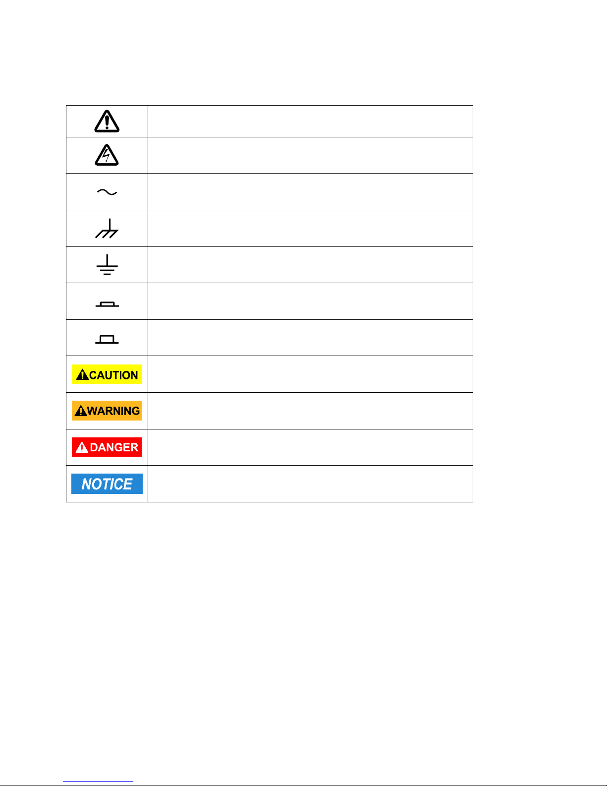
Safety Symbols
Refer to the user manual for warning information to avoid
hazard or personal injury and prevent damage to instrument.
Electric Shock hazard
Alternating current (AC)
Chassis (earth ground) symbol.
Ground terminal
On (Power). This is the In position of the power switch when
instrument is ON.
Off (Power). This is the Out position of the power switch when
instrument is OFF.
CAUTION indicates a hazardous situation which, if not avoided,
will result in minor or moderate injury
WARNING indicates a hazardous situation which, if not avoided,
could result in death or serious injury
DANGER indicates a hazardous situation which, if not avoided,
will result in death or serious injury.
NOTICE is used to address practices not related to physical injury.
9
Find Quality Products Online at: sales@GlobalTestSupply.com
www.GlobalTestSupply.com
Page 10
Contents
Product Overview ........................................................................................................... 15
Package Contents ........................................................................................................... 15
Dimensions ..................................................................................................................... 16
Front Panel Overview ..................................................................................................... 17
Front Panel Description ................................................................................................. 17
Rear Panel Overview ...................................................................................................... 18
Rear Panel Description ................................................................................................... 18
Display Overview ............................................................................................................ 19
Display Description ........................................................................................................ 19
Input Power Requirements ............................................................................................ 20
Input Power .................................................................................................................... 20
Fuse Requirements ........................................................................................................ 20
Fuse Replacement .......................................................................................................... 21
Leakage current ............................................................................................................. 21
Preliminary Check ........................................................................................................... 21
Safety Requirements ...................................................................................................... 21
Measurement Display Menu .......................................................................................... 23
Measurement Parameters .............................................................................................. 24
Primary Parameters ....................................................................................................... 24
Secondary Parameters ................................................................................................... 25
Parameter Combinations ............................................................................................... 25
Selecting Primary and Secondary Parameters ............................................................... 26
Test range ...................................................................................................................... 29
Test frequency ............................................................................................................... 29
10
Find Quality Products Online at: sales@GlobalTestSupply.com
www.GlobalTestSupply.com
Page 11
Test Signal Level ............................................................................................................. 30
DC BIAS ........................................................................................................................... 31
Test speed ...................................................................................................................... 32
Digits Resolution ............................................................................................................ 32
Zoom .............................................................................................................................. 33
Correction ....................................................................................................................... 34
Sweep Correction ........................................................................................................... 36
Short Correction ............................................................................................................. 37
Load Correction (Point-Frequency Correction) ............................................................. 38
Cable Length Selection ................................................................................................... 41
Impedance Parameters .................................................................................................. 41
Series and Parallel Models ............................................................................................. 43
Choosing a Test Frequency ............................................................................................ 43
Choosing a Measurement Circuit Model ....................................................................... 44
Measure Setup Menu ..................................................................................................... 46
Trigger Mode (TRIG) ....................................................................................................... 47
Auto Level Control (ALC) ................................................................................................ 48
Bias Current Isolation ..................................................................................................... 48
Average (AVG) ................................................................................................................ 49
Level Monitor (Vm/Im) .................................................................................................. 49
Delay Time (DELAY) ........................................................................................................ 50
Output Impedance ......................................................................................................... 50
Deviation Test Function (DEV A/DEV B) ......................................................................... 51
Measurement Parameters (PARAM) .............................................................................. 53
Swap Parameters ........................................................................................................... 53
Compare Function Modes (MODE) ................................................................................ 53
Tolerance Mode ............................................................................................................. 54
Auxiliary Bin (AUX) ......................................................................................................... 55
Comparator Function (COMP) ........................................................................................ 56
Enabling Compare Function ........................................................................................... 56
11
Find Quality Products Online at: sales@GlobalTestSupply.com
www.GlobalTestSupply.com
Page 12
High/Low Limits .............................................................................................................. 56
Bin Count Display ........................................................................................................... 58
PARAM ........................................................................................................................... 59
NOM. .............................................................................................................................. 59
COUNT ............................................................................................................................ 59
BIN .................................................................................................................................. 60
HIGH/LOW ...................................................................................................................... 60
AUX ................................................................................................................................. 60
OUT ................................................................................................................................ 60
No. ............................................................................................................................. 61
Mode ......................................................................................................................... 62
Sweep Parameter ...................................................................................................... 62
Limit Parameters ....................................................................................................... 63
High/Low Limits ......................................................................................................... 64
Delay .......................................................................................................................... 64
List Sweep Display Fields................................................................................................ 66
Running a List Sweep Example....................................................................................... 67
System Setup .................................................................................................................. 72
Pass Beep ....................................................................................................................... 72
Fail Beep ......................................................................................................................... 73
Language ........................................................................................................................ 73
Password ........................................................................................................................ 74
Bus Mode ....................................................................................................................... 74
GPIB ADDR (895 only) .................................................................................................... 74
Talk Only......................................................................................................................... 75
Bias SRC .......................................................................................................................... 75
Baud Rate ....................................................................................................................... 75
12
Find Quality Products Online at: sales@GlobalTestSupply.com
www.GlobalTestSupply.com
Page 13
Date/Time ...................................................................................................................... 75
LAN Setup ....................................................................................................................... 76
Default Settings and System Reset ................................................................................. 77
File Management ........................................................................................................... 77
Setup file (*.STA) ............................................................................................................ 78
Save Screenshot ............................................................................................................. 81
Save Measurements File ................................................................................................ 81
USB Flash Driver Requirements ..................................................................................... 81
Basic Accuracy A ............................................................................................................. 85
Measurement Accuracy Ae ............................................................................................ 86
Measurement Correction Factors .................................................................................. 86
Accuracy of D ................................................................................................................. 90
Accuracy of Q ................................................................................................................. 90
Accuracy of θ .................................................................................................................. 90
Accuracy of G ................................................................................................................. 90
Accuracy of Rp ............................................................................................................... 91
Accuracy of Rs ................................................................................................................ 91
Accuracy of DCR ............................................................................................................. 91
Accuracy of leakage inductance Lk ................................................................................ 91
Accuracy Calculation Examples ...................................................................................... 92
Example 1 ....................................................................................................................... 92
Example 2 ....................................................................................................................... 93
.................................................................................................. 96
RS-232 ............................................................................................................................ 96
USB (USBCDC - Virtual COM ) ........................................................................................ 97
USBTMC ......................................................................................................................... 97
LAN (Ethernet) ............................................................................................................... 97
GPIB (895 Only) .............................................................................................................. 98
Remote Commands ........................................................................................................ 98
13
Find Quality Products Online at: sales@GlobalTestSupply.com
www.GlobalTestSupply.com
Page 14
Technical description ...................................................................................................... 99
Handler Operation ........................................................................................................ 100
Electrical features ......................................................................................................... 107
HANDLER Interface Board Circuit ................................................................................ 108
Handler ......................................................................................................................... 110
Operation ..................................................................................................................... 110
14
Find Quality Products Online at: sales@GlobalTestSupply.com
www.GlobalTestSupply.com
Page 15

1. General Information
Product Overview
The B&K Precision models 894 and 895 are precision bench LCR meters. They are capable of
measuring the capacitance, inductance and resistance of components with basic accuracy
of 0.05%. These meters have an adjustable test frequency, from 20 Hz to 500 kHz (894) and
20 Hz to 1 MHz (895). With the vivid 4.3-inch TFT LCD, users can operate and read the
measurements easily. This LCR meter is designed to fit standard 19in racks with a 2U form
factor.
The sweep function provides a quick look at the characteristics of the components, allowing
the customer to systematically test the primary and secondary parameters of those
components using up to 201 frequencies. The BIN comparator function helps quickly sort
components up to 10 bins. With built-in USB, RS-232, LAN and GPIB (895 only), these LCR
meters can be remotely controlled to perform daily operations in production, quality
control and laboratory environments.
Features:
• Basic accuracy 0.05%
• Test frequency from 20 Hz to 500 KHz (894) and 1 MHz (895)
• Frequency sweep function
• Bin sorting comparator
• Adjustable measurement speed for fast readout or better accuracy
• Standard USB, Ethernet, RS-232C and GPIB interface (895 only)
• Save and recall up to 40 internal measurement setups
• 4.3” color TFT LCD display
Package Contents
Please inspect the instrument mechanically and electrically upon receiving it. Unpack all
items from the shipping carton, and check for any obvious signs of physical damage that
may have occurred during transportation. Report any damage to the shipping agent
immediately. Save the original packing carton for possible future reshipment. Every
instrument is shipped with the following contents:
1 x Model 894/895 bench LCR meter
1 x AC power cord
1 x 4-wire Kelvin clip test lead
1 x 4-terminal test fixture
1 x Certificate of Calibration
1 x Test Report
1 x Shorting Bar
15
Find Quality Products Online at: sales@GlobalTestSupply.com
www.GlobalTestSupply.com
Page 16
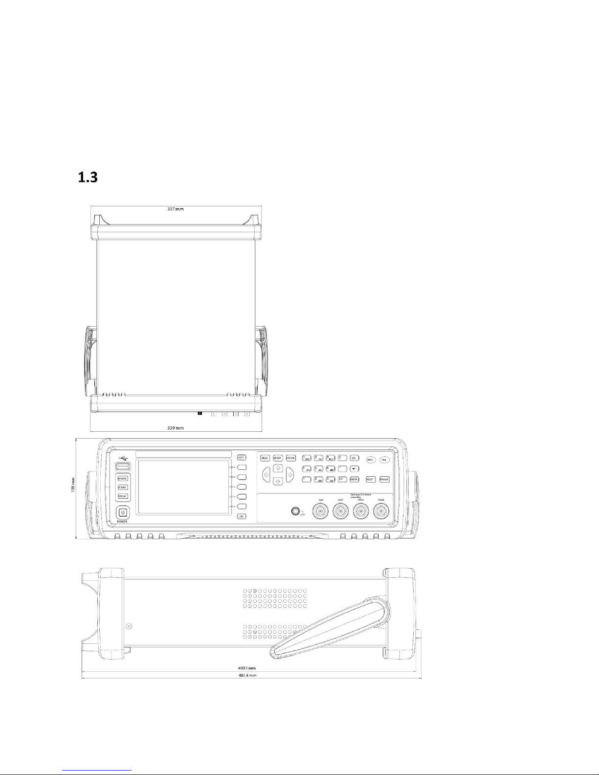
Dimensions
Figure 1 - Dimensions
16
Find Quality Products Online at: sales@GlobalTestSupply.com
www.GlobalTestSupply.com
Page 17
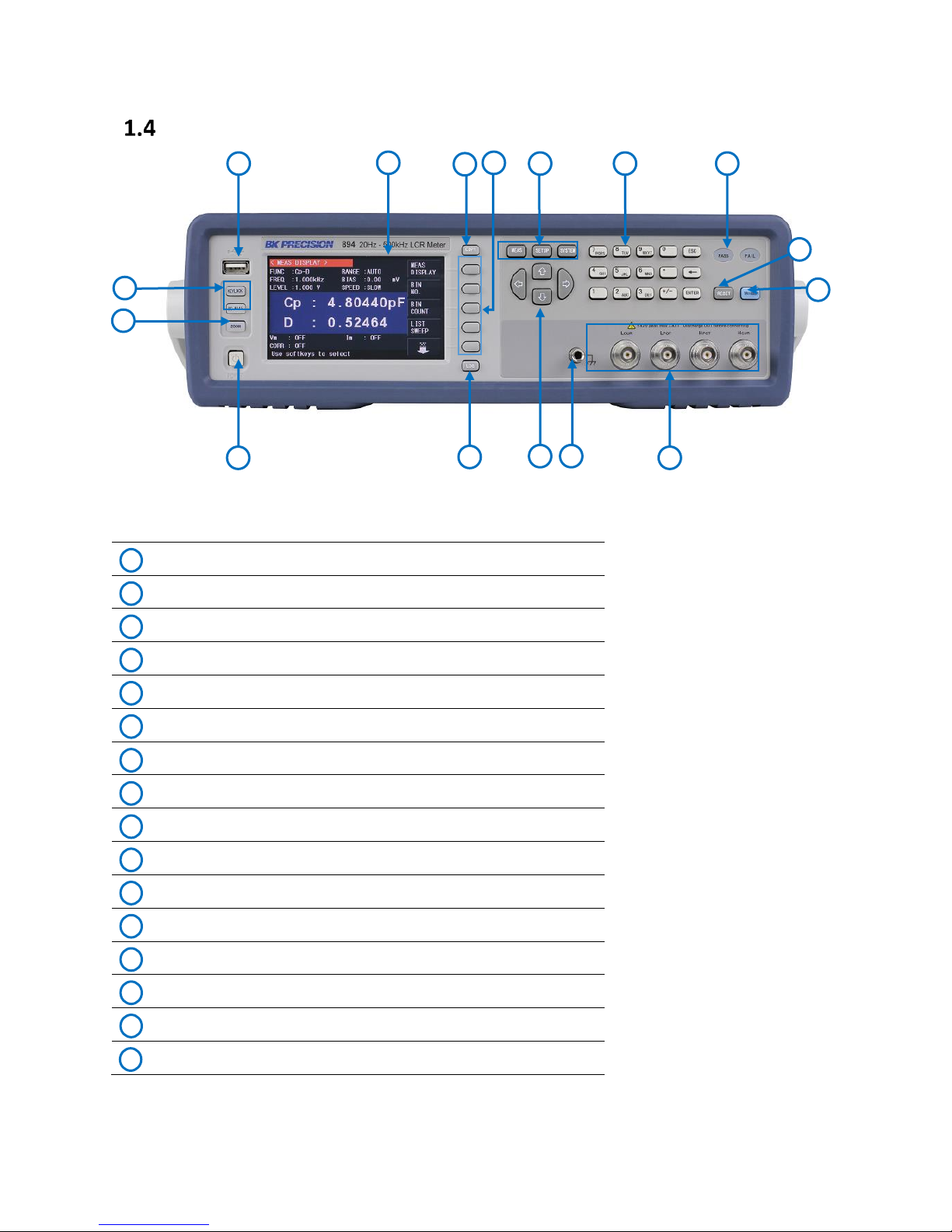
Front Panel Overview
Power On/Off Switch
Log Key
Cursor
Ground Terminal
Measurement Terminals
Trigger Key
Reset Key
Pass/Fail LED indicators
Numerical Keypad
Menu Keys: MEAS, SETUP and SYSTEM
Softkeys
Copy Key
4.3” TFT Color LCD Display Window
USB Host Port
Auxiliary Keys
Zoom Button
1
4
13 6 7 8 9
14
11
10
15
2
5
12
16
1 2 3
4 5 6 7 8 9 10
11
12
13
14
15
16
Front Panel Description
Figure 2 - Front Panel Overview
17
Find Quality Products Online at: sales@GlobalTestSupply.com
www.GlobalTestSupply.com
Page 18
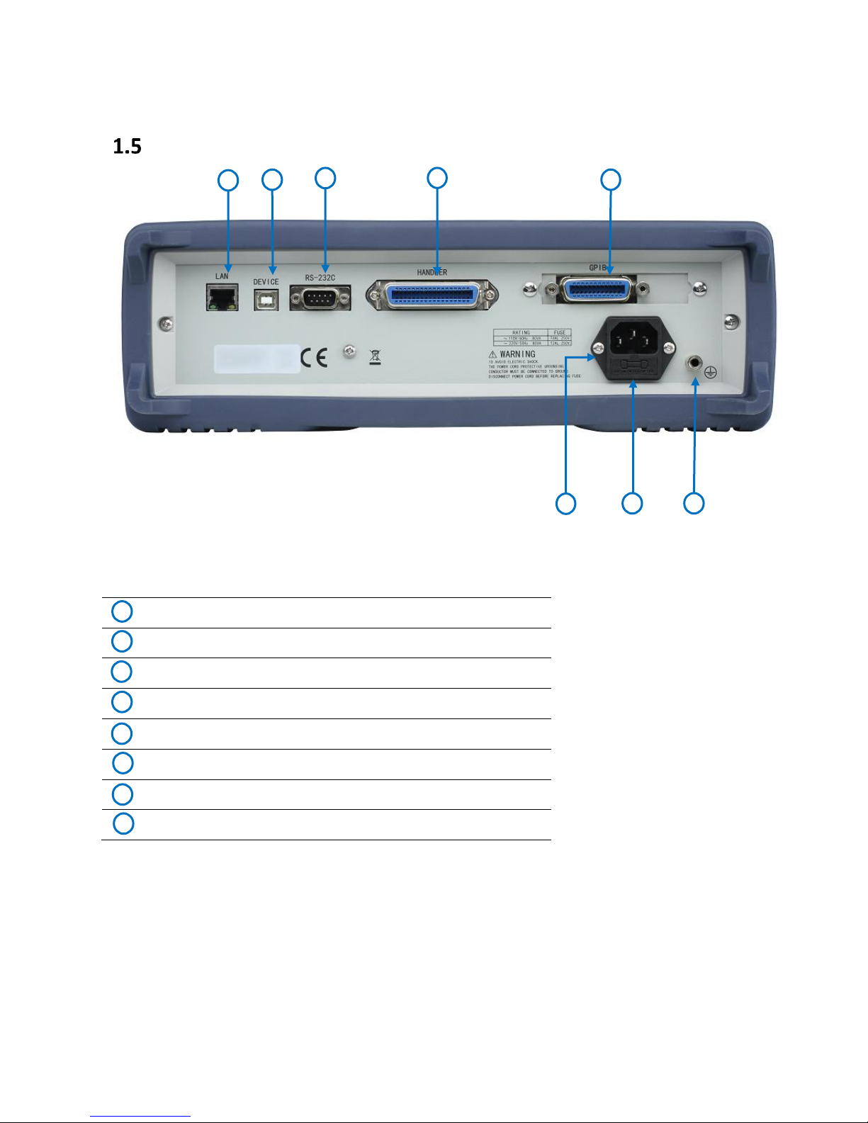
AC Power Input Receptacle
Fuse Box
Chassis Ground Terminal
GPIB Interface (895 only)
Handler Interface
RS-232 Interface
USB Interface
LAN Interface
4 5 6 8 7
3 2 1
1 2 3
4
5 6 7
8
Rear Panel Overview
Rear Panel Description
Figure 3 - Rear Panel Overview
18
Find Quality Products Online at: sales@GlobalTestSupply.com
www.GlobalTestSupply.com
Page 19
Display Overview
Main Display Field
Displays measurement parameters and results
Menu Functions
Displays measurement settings
Menu Options
Displays menu options
1 2 3
2
1
3
Display Description
Figure 4 - Display Overview
19
Find Quality Products Online at: sales@GlobalTestSupply.com
www.GlobalTestSupply.com
Page 20
Getting Started
The included AC power cord is safety certified for this instrument operating in rated range.
To change a cable or add an extension cable, be sure that it can meet the required power
ratings for this instrument. Any misuse with wrong or unsafe cables will void the warranty.
Before replacing fuse, disconnect AC input power cord first to prevent electric shock.
Only use a fuse of the same rating as required. Using a different rated fuse will damage the
instrument.
Model
Fuse Specification (110 V)
Fuse Specification (220 V)
894
T 4AL, 250 V
T2AL, 250 V
895
T 4AL, 250 V
T2AL, 250 V
Before connecting and powering up the instrument, please review and go through the
instructions in this chapter.
Input Power Requirements
Input Power
The instrument has a selectable AC input that accepts line voltage and frequency input
within:
AC Input: 100-120 VAC or 198-242 VAC
Frequency: 47 – 63 Hz
Before connecting to an AC outlet or external power source, be sure that the fuse is the
appropriate for the mains (refer to Fuse Requirements). Also, verify that the AC power cord,
including the extension line, is compatible with the rated voltage/current and that there is
sufficient circuit capacity for the power supply. Once verified, connect the cable firmly.
Fuse Requirements
An AC input fuse is necessary when powering the instrument. The fuse is located at the
back of the instrument. In the event the fuse needs to be replaced, make sure the AC input
power cord is disconnected from the instrument before replacing. Refer to the table below
for the fuse requirements with either 115 VAC or 230 VAC.
Table 1 - Fuse Requirements
Find Quality Products Online at: sales@GlobalTestSupply.com
www.GlobalTestSupply.com
20
Page 21
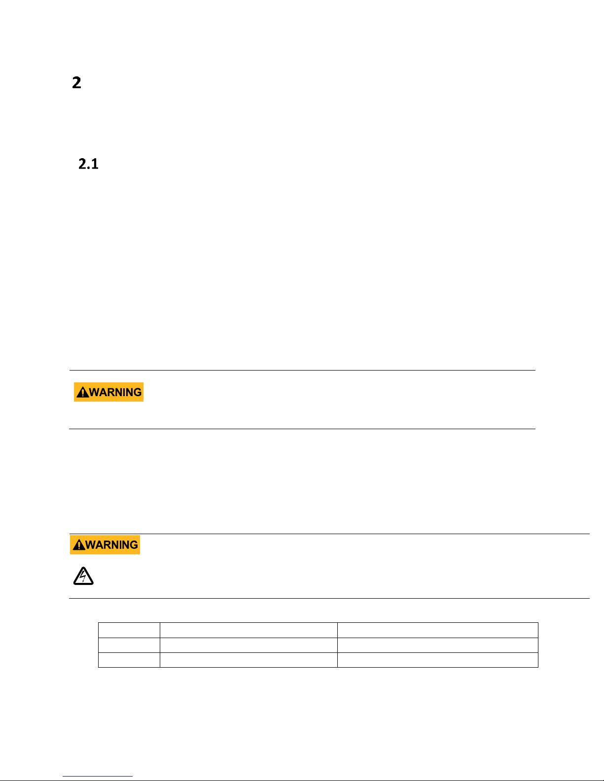
Fuse Replacement
Fuse box slit
Fuse box
Check/Remove Fuse
- Locate the fuse box next to the AC input connector in the rear panel
- With a small flat blade screwdriver, insert into the fuse box slit to pull and slide out the
fuse box as indicated below.
- Check and replace fuse if necessary.
Figure 5 - Fuse replacement
Leakage current
The leakage current should not be larger than 3.5 mA (AC effective value).
Preliminary Check
Complete the following steps to verify that the instrument is ready for use.
Verify AC Input Voltage
Verify and check to make sure proper AC voltages are available to power the instrument.
The AC voltage range must meet the acceptable specification as explained in previous
section.
Connect Power
Connect AC power cord to the AC receptacle in the rear panel and press the power switch
to the ON position to turn ON the instrument. The instrument will have a boot screen while
loading, after which the main screen will be displayed.
Safety Requirements
The 894/895 are CAT I safety rated.
Normal working conditions: (0
Find Quality Products Online at: sales@GlobalTestSupply.com
www.GlobalTestSupply.com
~40, relative humidity ≤75%).
21
Page 22
1
3
4
2
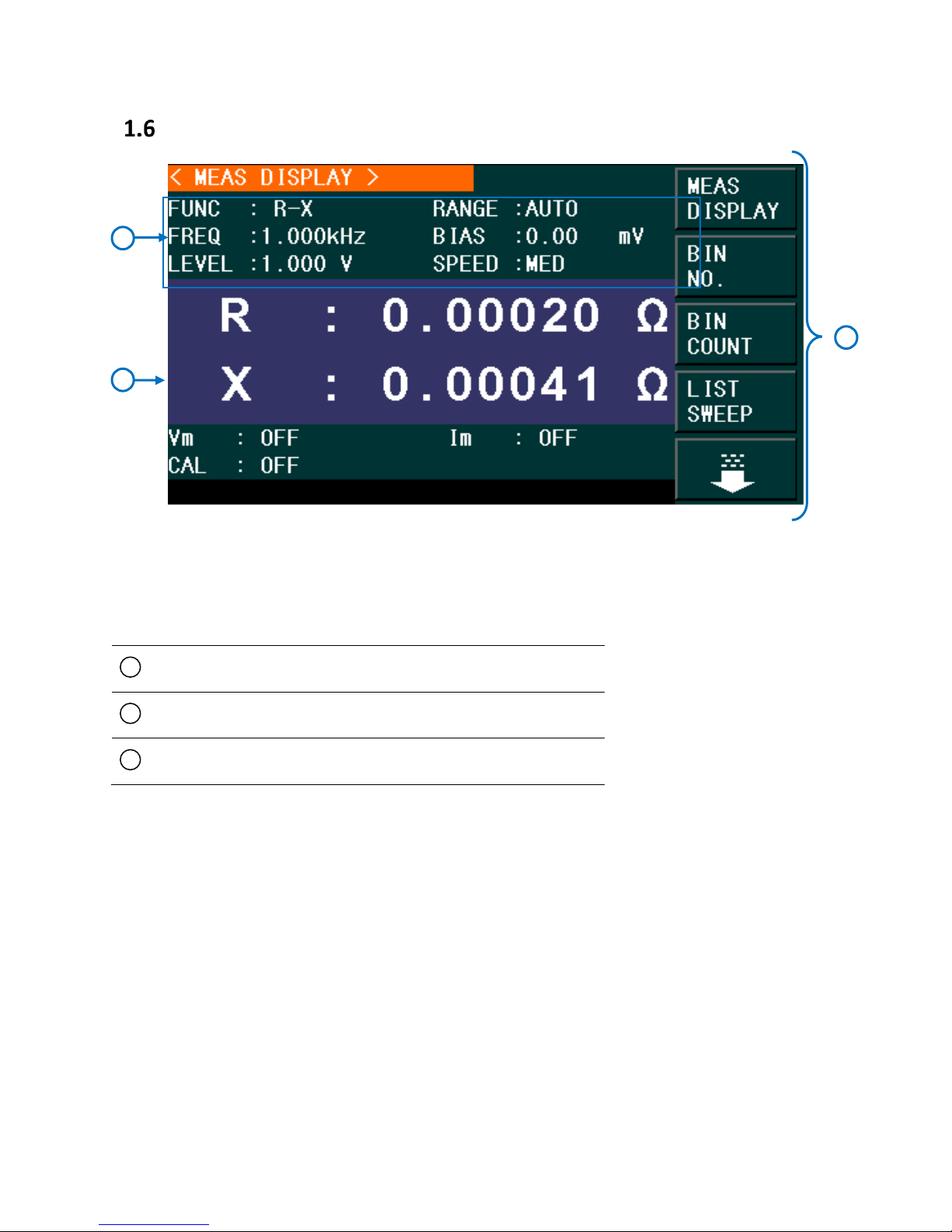
Making Measurements
The meter has a 4.3-inch TFT display. The Measurement Display screen is divided into the
following zones:
Figure 6 - Measurement Display Fields
Measurement Display Fields Description
1. Display page name
Indicate the name of the currently displayed page.
2. Soft menu keys
Displays on-screen soft keys for navigating soft menu items.
3. Measurement display field
Displays measurement results.
4. Information
Displays information about signal source and correction.
Find Quality Products Online at: sales@GlobalTestSupply.com
www.GlobalTestSupply.com
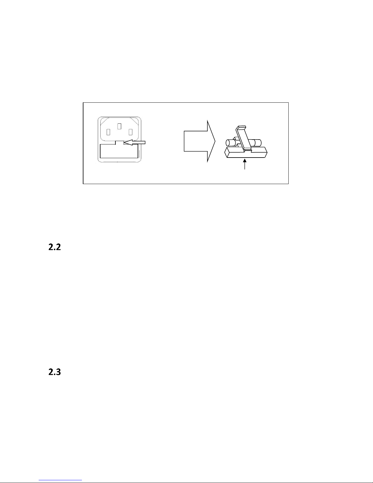
Page 23
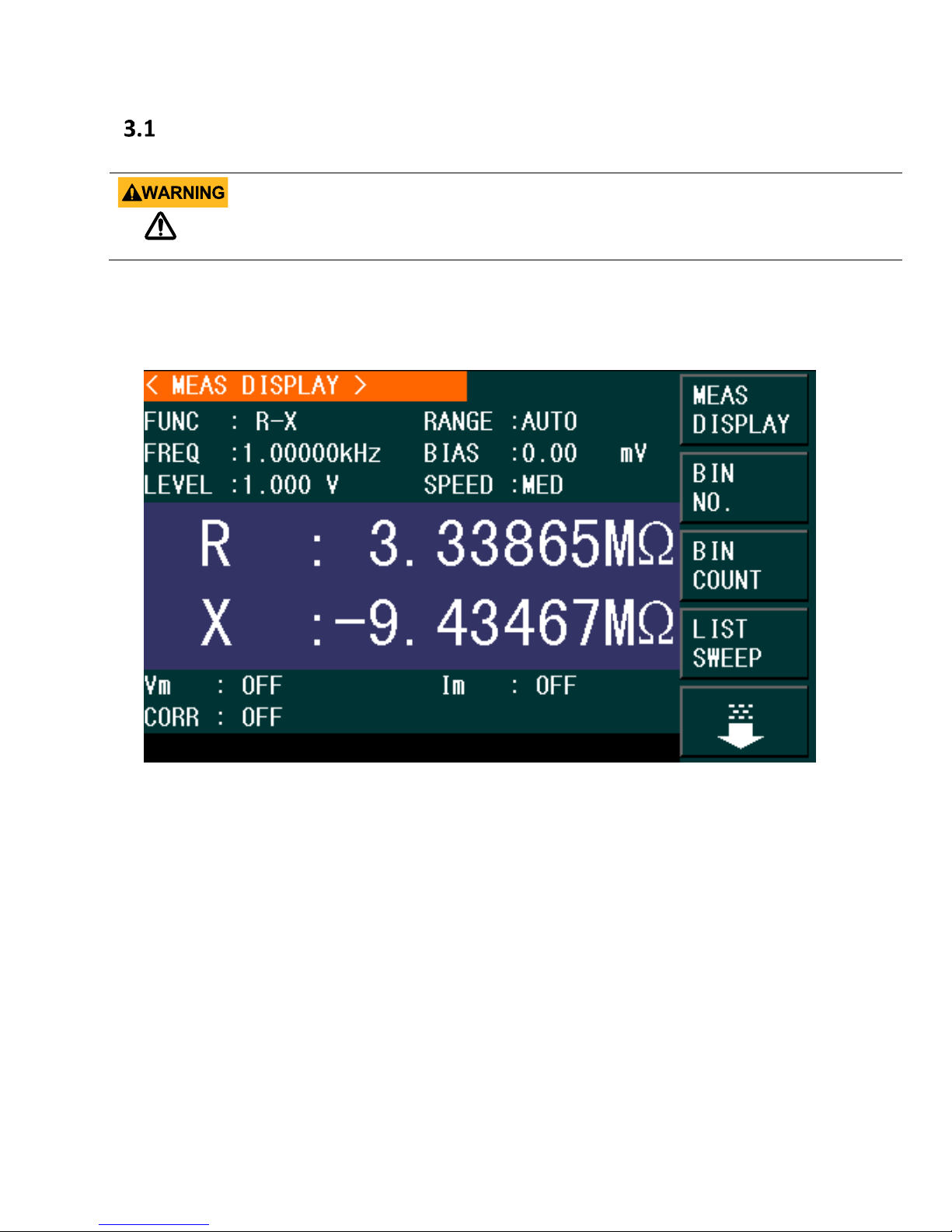
Measurement Display Menu
If the component under test is a capacitor, make sure the capacitor has been fully discharged
before connecting it to the instrument. Failing to discharge the capacitor may damage the
instrument and may void the warranty.
To measure a component, connect it to the test leads or insert it into the test fixture (i.e. the 4wire Kelvin clip test lead or the 1 x 4-terminal text fixture). Press [MEAS], the <MEAS DISPLAY>
page will be displayed on the main screen:
Figure 7 - Measurement Display Menu
The measurement parameters that can be set in this page are:
Test function (FUNC)
Test frequency (FREQ)
Test level (LEVEL)
Test range (RANGE)
DC Bias (BIAS)
Test speed (SPEED)
The Measurement Display field shows the primary and secondary measurements results. In
addition, the “Information” field displays the value of the output voltage and current if the
voltage and current monitors are enabled. Otherwise, the unit will display “OFF”. The CORR
(Correction) field will display the type of correction that is enabled: Open, Short and/or Load.
23
Find Quality Products Online at: sales@GlobalTestSupply.com
www.GlobalTestSupply.com
Page 24
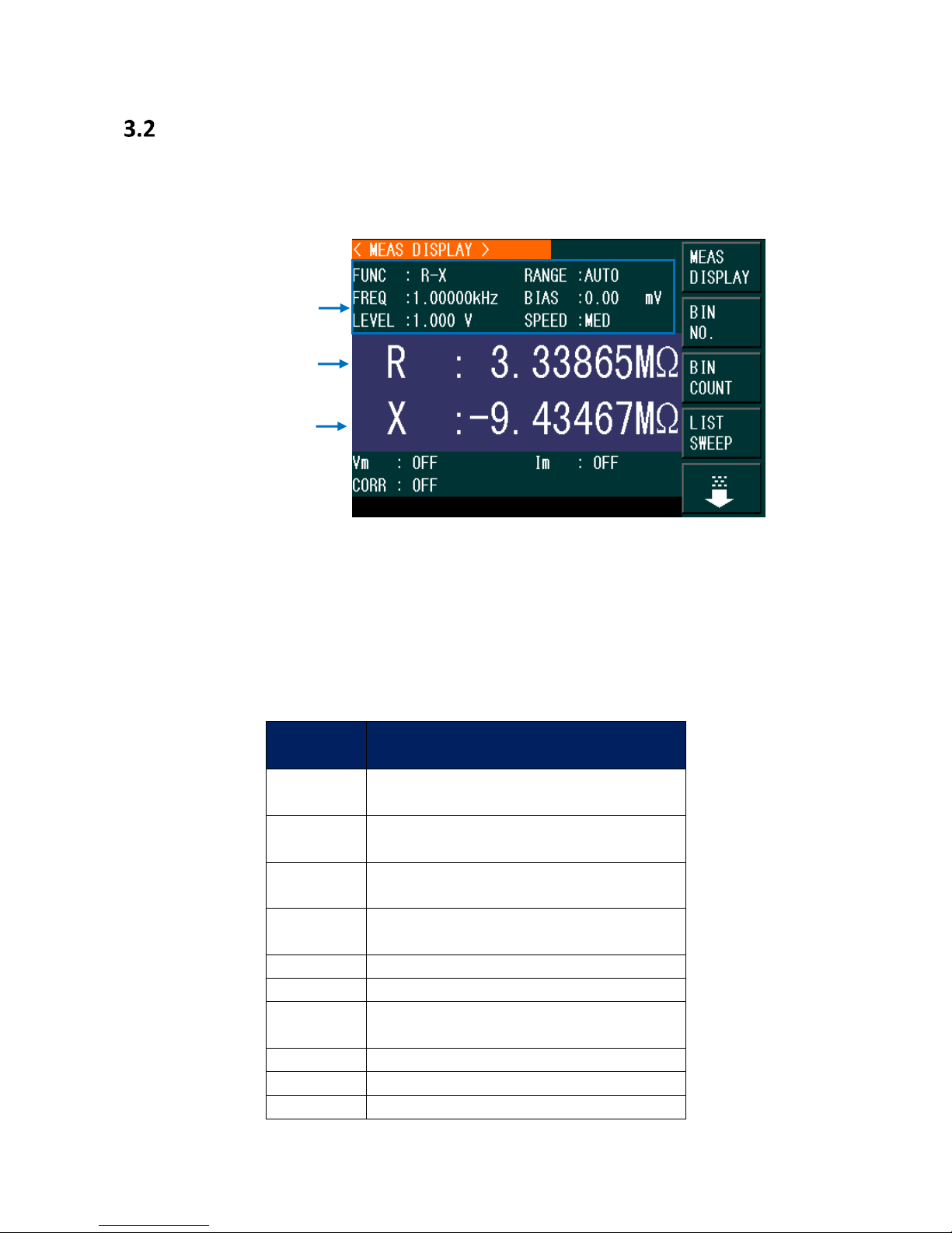
Measurement Parameters
Parameter
Description
Cp
Capacitance measured using a parallel
equivalent circuit model
Cs
Capacitance measured using a series
equivalent circuit model
Lp
Inductance measured using a parallel
equivalent circuit model
Ls
Inductance measured using a series
equivalent circuit model
Z
Impedance
Y
Admittance
R
Resistance using a specified AC
frequency and level
G
Conductance
DCR
Resistance using a DC bias.
L2-A*
Primary Inductance
Primary
Measurement
Secondary
Measurement
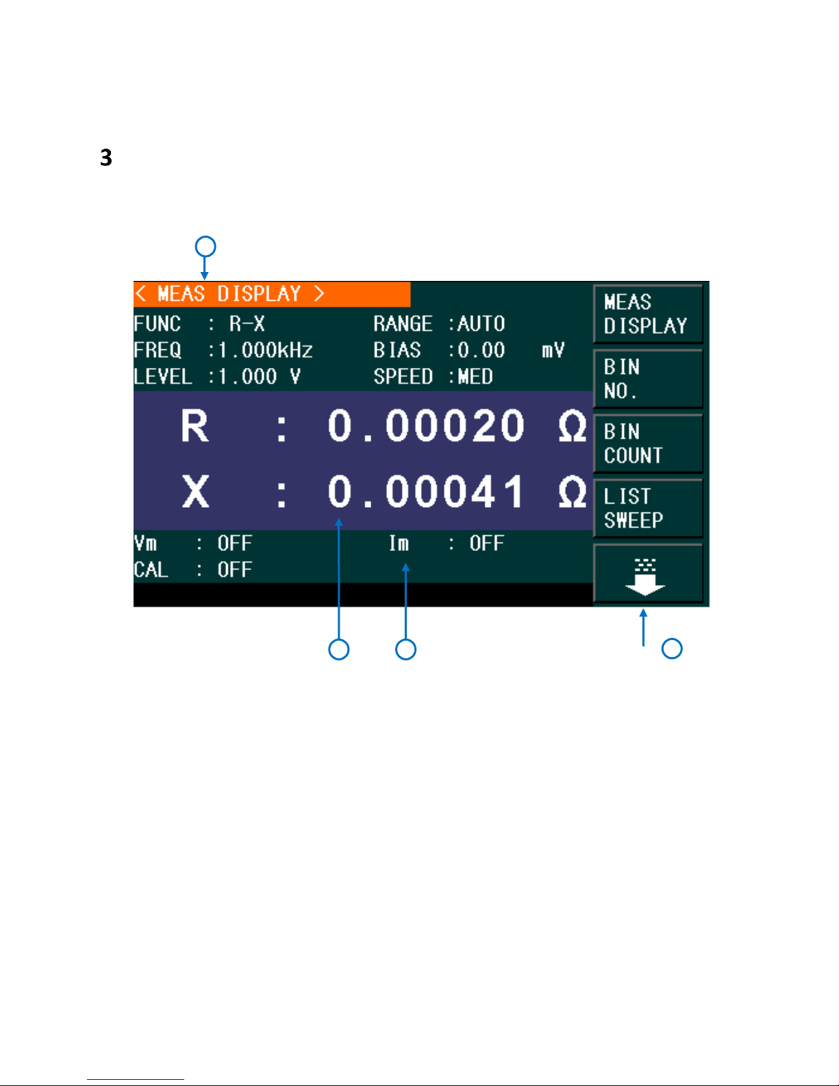
Measurement
Parameters
The Measurement Parameters field lets the user select different settings for the measurement
to be taken.
Figure 8 - Measurement Function Display
Test results of the primary and secondary parameters are displayed in two lines. The primary
parameter is displayed in the upper line while the secondary parameter is displayed in the lower
line.
Primary Parameters
24
Find Quality Products Online at: sales@GlobalTestSupply.com
www.GlobalTestSupply.com
Page 25
L2-B*
Secondary Inductance
*Used with transformer test fixture TL89T1.
Parameter
Description
Q
Quality factor
D
Dissipation factor
Rs
Equivalent Series Resistance (ESR)
Rp
Equivalent Parallel Resistance
X
Reactance
B
Admittance
Θ
Phase Angle
N, 1/N*
Turn Ratio and Polarity
M*
Mutual Inductance
R2
DC Resistance
Primary
Parameter
Series Mode
Combinations
Parallel Mode
Combinations
C
Cs-Q
Cs-D
Cs-Rs
Cp-Q
Cp-D
Cp-Rp
Cp-G
L
Ls-Q
Ls-D
Ls-R
Lp-Q
Lp-D
Lp-Rp
Lp-G
Primary
Parameter
Combinations
Z
d
r
Y
d
r
Secondary Parameters
*Used with transformer test fixture TL89T1.
Parameter Combinations
Table 2 - Primary Parameters
Table 3 - Secondary Parameters
The combinations of primary and secondary parameters, including the series and parallel
combinations are listed below:
Table 4 – Primary Parameter Combinations: Series and Parallel
Find Quality Products Online at: sales@GlobalTestSupply.com
www.GlobalTestSupply.com
25
Page 26

R
X
Rp-X
Rp-Q
G-B
N/A
DCR
N/A
L2A*
N
1/N
M
R2
L2B*
N
1/N
M
R2
Table 5 – Additional Primary Parameter Combinations
*Used with transformer test fixture TL89T1.
Selecting Primary and Secondary Parameters
1) Move the cursor to select FUNC field , and the following soft keys will be displayed on
the screen.
Cp—…→
Cs—…→
Lp—…→
Ls—…→
↓
2) Press the soft key corresponding to Cp—…→ to select Cp as the primary parameter,
and the following parameters will be displayed:
Cp-D
Cp-Q
Cp-G
Cp-Rp
←
Press the soft key to select the secondary parameter. Then press ← to return to the
previous menu.
3) Press Cs—…→ to select Cs as the primary parameter, and the following parameters
will be displayed:
Cs-D
Find Quality Products Online at: sales@GlobalTestSupply.com
www.GlobalTestSupply.com
26
Page 27

Cs-Q
Cs-Rs
←
Press the soft key to select the secondary parameter. Then press ← to return to the
previous menu.
4) Press Lp—…→ to select Lp as the primary parameter, and the following parameters
will be displayed:
Lp-D
Lp-Q
Lp-G
Lp-Rp
←
Press the soft key to select the secondary parameter. Then press ← to return to the
previous menu.
5) Press Ls—…→ to select Ls as the primary parameter, and the following parameters will
be displayed:
Ls-D
Ls-Q
Ls-Rs
←
Press the soft key to select the secondary parameter. Then press ← to return to the
previous menu.
6) Press ↓ to see more parameter options, and the following will be displayed.
Z—…→
Y—…→
R—…→
↑
↓
7) Press Z—…→ to select Z as the primary parameter, and the following parameters will
be displayed:
Z-d
Z-r
←
Press the soft key to select the secondary parameter. Then press ← to return to the
previous menu.
8) Press Y—…→ to select Y as the primary parameter, and the following parameters will
27
Find Quality Products Online at: sales@GlobalTestSupply.com
www.GlobalTestSupply.com
Page 28

be displayed.
Y-d
Y-r
←
Press the soft key to select the secondary parameter. Then press ← to return to the
previous menu.
9) Press R—…→ to select R as the primary parameter, the following parameters will be
displayed.
R-X
Rp-Q
Rs-Q
←
Press the soft key to select the secondary parameter. Then press ← to return to the
previous menu.
10) Press ↓, the following parameters will be shown.
G-B
DCR
L2A—…→
L2B —…→
↑
11) Press G-B to select G as the primary parameter and B as the secondary parameter.
12) Press DCR to select DC resistance as the measurement parameter.
13) Press L2A-…→, the following parameters will be displayed:
L2A-N
L2A-1/N
L2A-M
L2A-R2
←
Press the soft key corresponding to the required parameter. Then press ← to return to the
previous menu.
14) Press L2B-…→. The following parameters will be displayed:
L2B-N
L2A-1/N
L2B-M
L2B-R2
←
28
Find Quality Products Online at: sales@GlobalTestSupply.com
www.GlobalTestSupply.com
Page 29
Press the soft key to select the secondary parameter. Then press ← to return to the
Note: When the test function is set to DCR, the FREQ field will display “---”.
Frequency range (F)
Test frequency point
Resolution
20 Hz ≤ F ≤ 99.99 Hz
20.00 Hz, 20.01Hz ……99.99 Hz
0.01 Hz
100 Hz ≤ F ≤ 999.9 Hz
100.0 Hz, 100.1Hz ……999.9 Hz
0.1 Hz
1 kHz ≤ F ≤ 9.999 kHz
1.000 kHz, 1.001 kHz ……9.999 kHz
1 Hz
10 kHz ≤ F ≤ 99.99 kHz
10.00 kHz, 10.01 kHz……99.99 kHz
10 Hz
100 kHz ≤ F ≤ 1 MHz
100.0 kHz, 100.1 kHz……1 MHz
100 Hz
previous menu.
Note: L2A and L2B should be used with transformer test fixture TL89T1.
Test range
The measurement range should be selected in accordance with the impedance value of the
tested LCR component.
The 894/895 have 11 AC measurement ranges: 10Ω, 30Ω, 100Ω, 300Ω, 1kΩ, 3kΩ, 10kΩ,
30kΩ, 100kΩ, 300kΩ, and 1MΩ (895 only).
The 894/895 have 14 DCR measurement ranges: 30mΩ, 100mΩ, 300mΩ, 1Ω, 10Ω, 100Ω,
300Ω, 1kΩ, 3kΩ, 10kΩ, 30kΩ, 100kΩ, 300kΩ, and 1MΩ (895 only).
Setting the test range:
1) Move the cursor to the range field, the following soft keys will be displayed:
AUTO The soft key is used to set the range mode to AUTO.
HOLD The soft key is used to switch the AUTO mode to the HOLD mode. In this
mode, the range will be locked in the current measurement range, which is
displayed in the range field.
↑(+) The soft key is used to increase the range under HOLD mode.
↓(-) The soft key is used to decrease the range under HOLD mode.
2) Use the soft keys to set measurement range.
Test frequency
The frequency range of the 894 meter ranges from 20Hz to 500 KHz, and up to 1 MHz for
895.
Table 6 - Frequency Range, Test Frequency Points and Resolution
Setting the test frequency:
There are two ways to set measurement frequency: soft keys, numeric keys.
1) Move the cursor to the FREQ field, and the following soft keys will be displayed:
29
Find Quality Products Online at: sales@GlobalTestSupply.com
www.GlobalTestSupply.com
Page 30
↑(++) This is a coarse adjustment soft key used to increase the frequency. Press
Hz
Hz
kHz
kHz
kHz
MHz
20
100
1.0
10
100
1*
25
120
1.2
12
120
30
150
1.5
15
150
*895 only
40
200
2.0
20
200 50
250
2.5
25
250 60
300
3.0
30
300
80
400
4.0
40
400
500
5.0
50
500
600
6.0
60
600*
800
8.0
80
800*
Voltage Level
Resolution
5 mVrms – 100 mVrms
100 μVrms
100 mVrms – 1 Vrms
1m Vrms
this key to change the frequency in the following sequence: 20Hz, 100Hz, 1 kHz, 10
kHz, 100 kHz, 500 KHz (894) and 1 MHz (895).
↑(+) This is a fine adjustment soft key used to increase the frequency. Press this
key, to change the frequency between the following values:
Table 7 - Test Frequencies
↓(-) This is a fine adjustment soft key used to decrease the frequency. The
selectable frequencies are the same as that of ↑ (+) in the above.
↓(--) This is a coarse adjustment soft key used to decrease the frequency. The
selectable frequencies are the same as that of ↑ (++) in the above.
2) Use soft keys or numeric keys to select the frequency. When using numeric keys, the
soft key displays the available frequency units (Hz, kHz and MHz). You can use them to
input the unit after entering the numeric value. If [ENTER] is pressed to input
frequency, the unit defaults to Hz.
Test Signal Level
The test signal level (current or voltage) can be configured using this function. The test signal
values available are the RMS equivalent of the sine wave signal. The corresponding current level
mode value has a linear relationship with the internal resistance.
The test signal level voltage has a valid range from 5 mVrms to 2 Vrms. The resolution will
change according to each range as follows:
30
Find Quality Products Online at: sales@GlobalTestSupply.com
www.GlobalTestSupply.com
Page 31

1 Vrms – 2 Vrms
10 mVrms
Table 8 - Voltage Level Resolution
Impedance
Current Range
30 Ω
166.7 μA to 66.7 mA
50 Ω
100.0 μA to 40.0 mA
100 Ω
50.0 μA to 20.0 mA
Note: When the test function is set to DCR, the LEVEL field will display “---”.
Note: When the test function is set to DCR, the BIAS field will display “---”.
The test signal level current range is as follows:
Table 9 - Current Range vs. Impedance
The Auto Level Control function (ALC) can measure constant voltage or current. It can be
enabled from the <MEAS> page. When it is ON, “ * ” will be displayed following the current
level value.
Setting the test level:
There are two ways to set the level of the test signal source: soft keys, numeric keys.
1) Move the cursor to LEVEL, and the following soft keys will be displayed.
↑(+) This soft key is used to increase the level of the test signal source.
↓(-) This soft key is used to decrease the level of the test signal source.
2) Use soft keys or numeric keys to set the test level. When using numeric keys, the soft
key displays the available units (mV, V, µA, mA and A). You can use them to input the
unit after entering the numeric value. If [ENTER] is pressed to input the level, the unit
defaults to V or A.
DC BIAS
The meter has an internal DC bias voltage from -5 V to +5 V and a current from -25 mA to 25mA.
Setting DC bias:
There are two ways to set the DC bias: Use soft keys and numeric keys. Move the cursor to
DC BIAS, and the following soft keys will be displayed.
↑(+) - This soft key is used to increase the output level of DC bias.
31
Find Quality Products Online at: sales@GlobalTestSupply.com
www.GlobalTestSupply.com
Page 32

↓(-) - This soft key is used to decrease the output level of DC bias.
Note: The fast and middle speed will be slow down when frequency <10 kHz.
1) Use soft keys or numeric keys to set the DC bias source. When using numeric keys, the
soft key displays the available units (mV, V, µA, mA and A). You can use them to input
the unit after entering the numeric value. If the [ENTER] button is pressed to input bias
value, the unit defaults to V or A.
Press the [DC BIAS] key on the front panel to enable DC bias output. The [DC BIAS] key will
be lid.
Test speed
The test speed is determined by the following factors:
Integration time (A/D conversion)
Average test times (average test times per test)
Measurement delay (from startup to the start of measurement)
Display time of test results
You can select FAST, MED or SLOW. Generally, test results are more stable and accurate when
set to SLOW.
Fast: Approx. 75 times/s (13 ms/reading)
Medium: Approx. 11 times/s (90 ms/time)
Slow: Approx. 2.7 times/s (370 ms/time)
Setting the test speed:
Move the cursor to SPEED, and the following soft keys will be displayed:
FAST
MED
SLOW
Use the soft keys to select the test speed.
Digits Resolution
The measurement results of the meter can display up to 6 floating-point digits. The 894 and
895 can be manually configured to display a fixed number of digits or automatically select
the number of digits based on range.
32
Find Quality Products Online at: sales@GlobalTestSupply.com
www.GlobalTestSupply.com
Page 33

Setting Decimal Resolution
NOTE: Under the following circumstances, the decimal lock function will be disabled automatically and return
to auto:
Changing the test function.
Changing the deviation test mode (ΔABS, Δ%, OFF) in deviation test mode.
1) Move the cursor to MEASUREMENT DISPLAY FIELD (Figure 6) to either the primary
measurement or secondary measurement and the following soft keys will be displayed:
Decimal Point Auto (D.P. Auto)
Decimal Point Hold (D.P. Fix)
Decimal Point Position Increment (D.P. POS INCR +)
Decimal Point Position Decrement (D.P. POS DECL -)
2) Press DECIMAL AUTO to reset the decimal position of the primary or the secondary
parameter test result to its default setting.
3) Press DECIMAL HOLD to lock the decimal location of the primary or the secondary
parameter test result.
4) Press DECIMAL LOCATION + to increase the displayed digit by ten times.
5) Press DECIMAL LOCATION - to decrease the displayed digit by ten times.
Zoom
The 894/895 LCR meters let the user enlarge the display size of the measurement results.
Press once the Zoom button to enlarge the measurement results display and press it
once more to return normal view. Refer to Figure 2 for more information.
Find Quality Products Online at: sales@GlobalTestSupply.com
www.GlobalTestSupply.com
33
Page 34
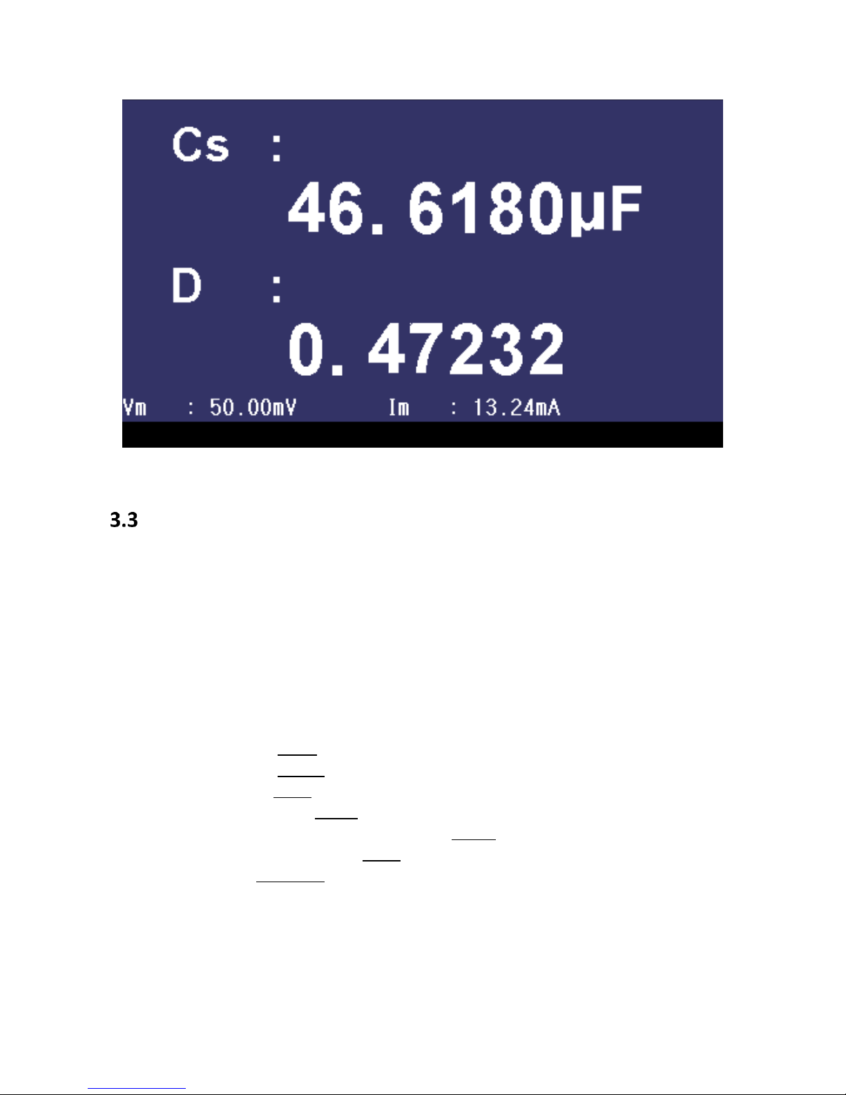
Figure 9 - Zoom
Correction
The user can perform OPEN, SHORT, and LOAD correction used to eliminate stray admittance,
residual impedances and other measurement errors. There are two correction methods.
Sweep correction: Performs an OPEN/SHORT correction at all pre-set frequency points.
Point frequency correction: Performs an OPEN/SHORT/LOAD correction at user-selected
frequencies.
The following parameters can be set on the <CORRECTION> page:
Open Correction (OPEN)
Short Correction (SHORT)
Load Correction (LOAD)
Cable length selection (CABLE)
Single/Multiple Correction mode selection (MODE)
Load Correction test function (FUNC)
Spot Number (SPOT No.)
Frequency points of OPEN, SHOR and LOAD (FREQ)
Reference values for frequency points ( REF A, REF B)
Open values for frequency points ( OPEN A, OPEN B)
Short values for frequency points ( SHORT A, SHORT B)
Load values for frequency points ( LOAD A, LOAD B)
34
Find Quality Products Online at: sales@GlobalTestSupply.com
www.GlobalTestSupply.com
Page 35
Note: There will be an indicator (>>>>>>>>===========) at the bottom of the screen showing the progress
of the correction operation.
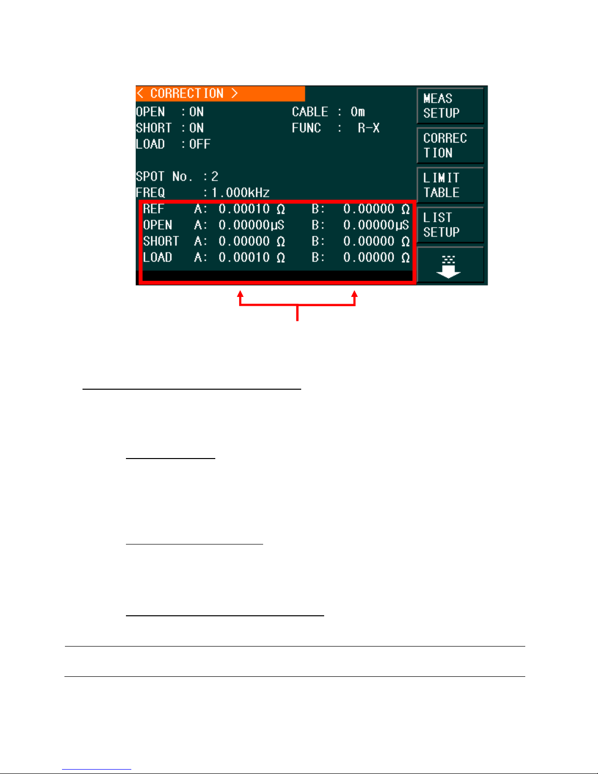
Correction Monitoring Zones.
Figure 10 – Correction/Correction Menu
The Correction Monitoring zones display the results of the load correction function (REF A and
B, OPEN A and B, SHORT A and B, LOAD A and B). These are the values that will be used to
compensate a measurement after an open, short and load calibration is performed.
The correction operation has three modes:
1. Sweep Correction:
When the FREQ option is set to OFF and the OPEN/SHORT option
s are set to ON, there will be an OPEN/SHORT correction over 48 pre-set
frequencies. Any frequency measurement not part of the 48 pre-set frequencies will
use an interpolation algorithm to calculate the correction factor for that specific
frequency.
2. Point-Frequency Correction:
When the FREQ option is set to ON and OPEN/SHORT/LOAD are also set to ON,
there will be an OPEN/SHORT/LOAD correction applied to all frequency points that
are identical to those specified by the user only. Up to 201 frequencies points are
applied.
3. No Correction applied to measurements: OPEN/SHORT/LOAD corrections can be
turned ON/OFF individually.
35
Find Quality Products Online at: sales@GlobalTestSupply.com
www.GlobalTestSupply.com
Page 36
Sweep Correction
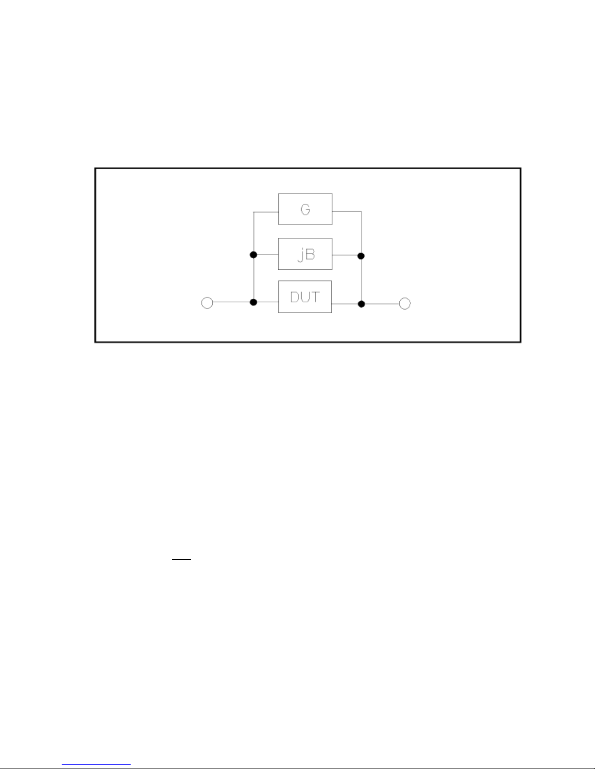
Open Correction
The open correction function can eliminate the errors caused by the stray admittance (G, B) that
may exist within the test fixture or leads. Refer to Figure 11.
Figure 11 - Stray Admittance
Open Correction Procedure
1) Connect the test fixture to the test terminal. Make sure the test fixture is not
connected to any DUT and it is “open”.
2) Press the SETUP button and enter the MEASURE SETUP menu.
3) Press the softkey, CORRECTION (displayed to the right of the screen in the soft key
zone), to enter the Correction menu. Press the down key and select the OPEN option.
The following soft keys will be displayed on the soft keys to the right of the screen:
ON: OPEN Correction adjustment to the current measurement.
Press ON to turn the function of open-circuit Correction on.
OFF: Turns off the OPEN Correction.
Press OFF to turn the OPEN correction off. There will be no OPEN Correction
performed in measurements.
MEAS OPEN: Measures the open conditions.
Press the MEAS OPEN softkey and the meter will test the open admittance
(capacitance and inductance) over 48 frequencies.
Note: This progress takes approximately 75 seconds to complete.
The following soft key will be displayed on the top right corner of the screen:
ABORT: This soft key cancels the current open correction operation.
36
Find Quality Products Online at: sales@GlobalTestSupply.com
www.GlobalTestSupply.com
Page 37
DCR OPEN: Tests the Open resistance for DCR.
The following soft key will be displayed on the top right corner of the display:
ABORT: This soft key cancels the current open correction operation.
4) Keep the test fixture open (no connection), then press the softkey MEAS OPEN to
execute open calibration. The meter will beep when the correction is completed.
Short Correction
The short correction feature compensates for any residual impedance that may exist within the
test fixture or leads, as shown in Figure 12. Short Correction uses 48 fixed frequencies to adjust
and compensate the input.
Short Correction Procedure
1) Connect the test fixture to the test terminal, or insert a shorting bar into the test
fixture.
2) Press the SETUP button and enter the MEASURE SETUP menu.
3) Press the softkey, CORRECTION, to enter the Correction menu. Press the Down
Key and select the SHORT option. The following soft keys will be displayed on the
soft keys to the right of the screen:
ON: Applies a SHORT correction adjustment to the current measurement.
Press ON to perform a short-circuit correction.
OFF: Turns off the SHORT correction.
Press OFF to turn the SHORT correction function off. There will be no Short
Correction performed in measurements.
MEAS SHORT: Tests the residual impedance (resistance and reactance) over the 48 pre-
set frequencies when shorted.
Figure 12 – Residual Inductance
37
Find Quality Products Online at: sales@GlobalTestSupply.com
www.GlobalTestSupply.com
Page 38

Press the MEASURE SHORT soft key. Full frequency correction takes approximately 75 seconds.
The following soft key will be displayed on the top right corner of the display:
ABORT: This soft key cancels the current short correction operation.
DCR SHORT: Short resistance test for DCR.
The following soft key will be displayed on the top right corner of the display:
ABORT: This soft key cancels the current short correction operation.
4) Insert the short plate to the test fixture.
5) Move the cursor to the SHORT zone. ON, OFF and MEAS SHORT will be displayed
in the soft key zone.
6) Press MEAS SHORT to execute the short calibration. The meter will beep when the
correction is completed
7) Press ON to turn the short calibration function.
8) Move the cursor to the LOAD zone. ON, OFF will be displayed in the soft key zone.
9) Press OFF to turn off the load calibration function.
10) Move the cursor to the FREQ zone, ON, OFF, MEAS OPEN, MEAS SHORT and
MEAS LOAD will be displayed in the soft key zone.
11) Press OFF to turn off the point-frequency calibration function of FREQ.
Load Correction (Point-Frequency Correction)
The Load Correction performs a correction at frequency points defined by the user (up to 201
frequencies). The preset frequencies can be set in the FREQ field of the display. The standard
reference values can be set in the setup zones of REF A and REF B.
The reference values of the component must be entered prior to performing a Load Correction.
38
Find Quality Products Online at: sales@GlobalTestSupply.com
www.GlobalTestSupply.com
Page 39

Figure 13 - Procedure for Correction at User-Specified Frequencies.
1. Connect the test fixture to the test terminal of the meter. Make sure the test fixture
is not connected to any device.
2. Press the SETUP button and enter the MEASURE SETUP menu.
3. Press the softkey, CORRECTION, to enter the Correction menu.
4. Press the ON softkey to enable LOAD correction. When Load Correction is enabled,
Short and Open Calibration will also be enabled for Point-Frequency Correction and
they can be enabled by turning them on.
5. Using the cursor keys and softkeys, set the standard test function in the FUNC field
(any settings entered will depend on this function).
6. Using the cursor keys, move the cursor to SPOT No. and select one spot (range from
1 to 201).
a. Enter a value using the numerical key pad or
b. Use the soft key: INCR++, INCR+, DECR-, and DECR--. The keys increment or
decrement the selected number by one (+,-) or by ten (++,--).
7. Press the Down Key and select the FREQ option.
8. Use numeric keys to input the correction frequency. After entering a numeric value,
the available unit softkeys (Hz, kHz and MHz) will be displayed. When the ENTER key
is used to input correction frequency, the unit defaults to Hz. The original preset
open/short/load Correction frequency data is displayed on the frequency setting
display field.
39
Find Quality Products Online at: sales@GlobalTestSupply.com
www.GlobalTestSupply.com
Page 40

The following softkeys will be displayed:
ON: Press this soft key to enable the open/short/load Correction data.
OFF: Press the soft key to disable the open/short/load Correction data.
MEAS OPEN: Press this soft key to execute open correction at the frequency
entered in step number 8.
MEAS SHORT: Press this soft key to execute short correction at the specified
frequency.
MEAS LOAD: Press this soft key to execute the load correction at FREQ selected in
step number 8.
9. Connect the test fixture to the test terminal.
OPEN CORRECTION
a. Disconnect any device under test from the test leads or test fixture and make
sure the test terminals are open (nothing connected).
b. Press MEAS OPEN to perform open correction at the current set frequency. The
test result (G, B) of the open correction test will be displayed at the bottom of
the screen.
c. Move the cursor to OPEN.
d. Press ON to perform an open correction calculation at the selected frequency in
later measurements.
SHORT CORRECTION
a. Disconnect any device under test from the test leads or test fixture and make
sure the test terminals are open (nothing connected).
b. Press MEAS SHORT to perform short correction at the current set frequency. The
test result (G, B) of the open correction test will be displayed at the bottom of
the screen.
c. Move the cursor to SHORT.
d. Press ON to perform a short correction calculation at the selected frequency in
later measurements.
LOAD CORRECTION
a. Using the cursors, navigate to REF A field.
b. Enter a known value or reference value (for the component to be used as a
standard) for the primary parameter set in the FUNC field.
c. Using the cursors, navigate to REF B field.
Enter a known value or reference value for the secondary parameter set in the
FUNC field (for the component to be used as a standard).
10. Move the cursor to the FREQ display field.
11. Connect the component to be used as a standard to the test fixture.
12. Press MEAS LOAD, and the instrument will execute a load correction. The real test
40
Find Quality Products Online at: sales@GlobalTestSupply.com
www.GlobalTestSupply.com
Page 41

results of the standard component will be displayed in LOAD A and LOAD B.
13. Press ON to perform load correction calculation at preset frequencies in later
measurements.
Cable Length Selection
The available cable length is 0m (when using the included 4-terminal test fixture), 1m, and
2m. To select the desired length, please follow the steps below:
1) Press the SETUP button.
2) Press the soft key Correction.
3) In the Correction menu, use the cursor keys to navigate to the Cable option.
4) Use the soft keys to select the desired length.
Impedance Parameters
Components such as inductors (L), capacitors (C), and resistors (R) can respond to test signals
with varying frequencies and levels in different ways. Large capacitors tested at high frequencies
can respond differently than when tested at lower frequencies. Large inductors tested at low
frequencies can respond differently than when tested at higher frequencies. In contrast,
resistors will respond relatively the same at high or low frequencies. Due to these
characteristics, it is very important to understand the complex impedance parameters of the
electronic components. The meter allows users to vary these test signals’ measurement
frequency, measurement level, and equivalent circuit choice to characterize the component
under test.
When analyzing the impedance using the impedance measurement plane (), it can be visualized
by the real element (Resistance) on the X-axis and the imaginary element (Reactance) on the Yaxis. This impedance measurement plane can also be seen as polar coordinates. |Z| is the
magnitude and θ is the phase of the impedance.
Figure 14 - Complex Impedance Plane
41
Find Quality Products Online at: sales@GlobalTestSupply.com
www.GlobalTestSupply.com
Page 42

X
∠
Ω
Ω
There are two different types of reactance: Inductive (XL) and Capacitive (XC). It can be defined
as follows:
For components, the quality factor (Q) serves as a measurement of the reactance purity. In the
real world, there is always some associated resistance that dissipates power, decreasing the
amount of energy that can be recovered. The quality factor can be defined as the ratio of the
stored energy (reactance) and the dissipated energy (resistance). Q is generally associated with
inductors and D (dissipation factor) for capacitors. Below shows the relationships between
these parameters:
42
Find Quality Products Online at: sales@GlobalTestSupply.com
www.GlobalTestSupply.com
Page 43

Series and Parallel Models
Series
Parallel
R
X
X
P
R
P
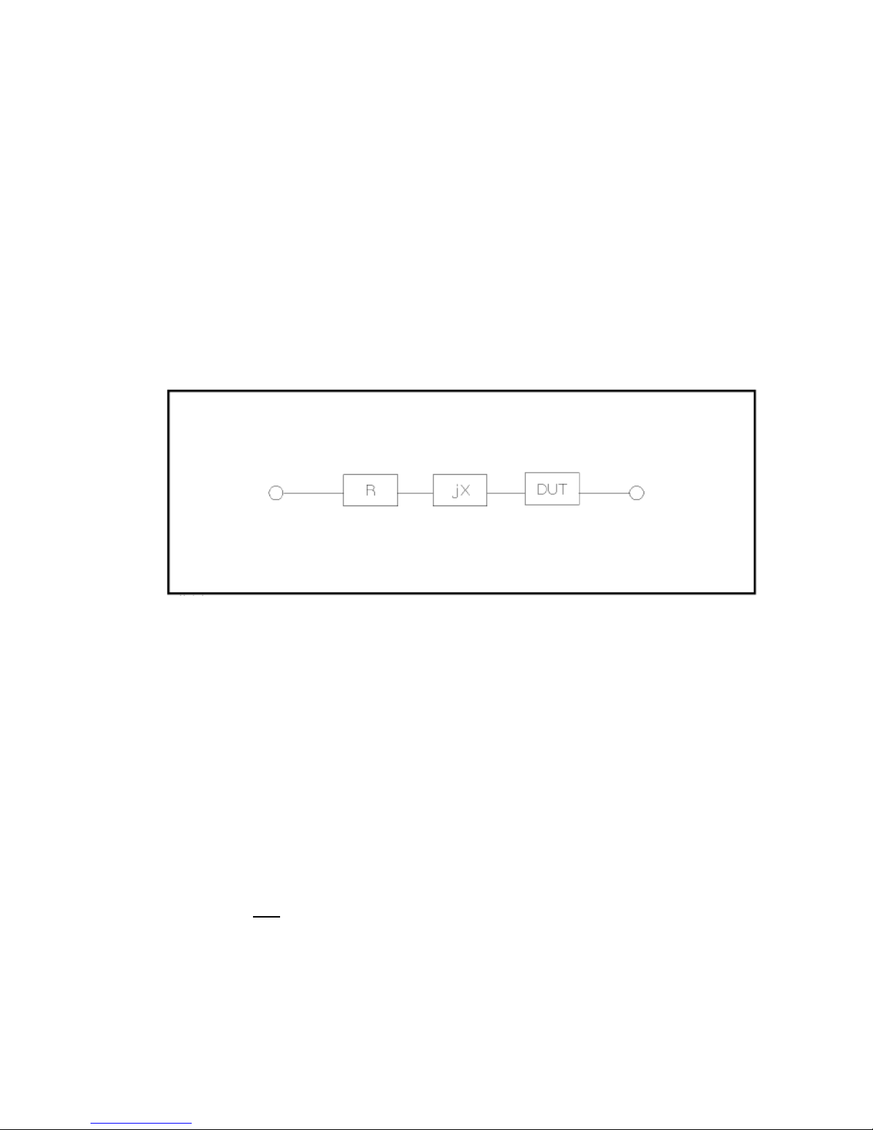
Components are modeled with one of the two following equivalent circuits:
Figure 15 - Series and Parallel Models
The impedance for the series model is:
The impedance for the parallel model is:
These circuit models are mathematically equivalent. The LCR meter measures an impedance,
which gives two independent numbers, the magnitude (|Z|) and phase (θ) of the impedance.
These are changed into rectangular components R and X, giving the real and imaginary part of
the impedance. These rectangular components can then be transformed into either a series or
parallel circuit of a pure resistance and pure reactance. These transformed circuits have exactly
the same impedance as the measured value, only at the measured frequency.
Choosing a Test Frequency
Test frequency can greatly affect the results of measurement reading, especially when
measuring inductors and capacitors. This section provides some recommendations and
suggestions to consider.
Capacitance
When measuring capacitance selecting, the right frequency is important in obtaining the
most accurate measurement results. Generally, a 1 kHz and above test frequency is used to
measure capacitors that are 0.01 µF or smaller. For capacitors that are 10 µF or larger, a
frequency of 1 kHz or lower can be used. Following this trend, high test frequencies are
best for testing very low capacitance components. For large capacitance components, low
43
Find Quality Products Online at: sales@GlobalTestSupply.com
www.GlobalTestSupply.com
Page 44

frequency would be optimal. For example, if the capacitance of the component is to be in
the mF range, then selecting in the range of 20 Hz to 200 Hz for test frequency would give
much better results. The results will also be obvious because if the same component was
tested with 1 kHz or above, the measured readings may look erroneous on the display.
In all cases, it is best to check with the manufacturer’s data sheet in order to determine the
best test frequency to use for measurement.
Inductance
Typically, a 1 kHz test frequency is used to measure inductors that are used in audio and RF
circuits. This is because these components operate at higher frequencies and require that
they be measured at higher frequencies above 1 kHz. However, a 120 Hz test signal is used
to measure inductors that are used for applications such as filter chokes in power supplies,
which are typically operated at 60 Hz AC (in U.S.) with 120 Hz filter frequencies.
In general, inductors below 2 mH should be measured at 1 kHz frequency while inductors
above 200 H should be measured at 120 Hz.
In all cases, it is best to check with the manufacturer’s data sheet in order to determine the
best test frequency to use for measurement.
Choosing a Measurement Circuit Model
There are two measurement circuit models to choose from, series or parallel, when
characterizing components under test. The LCR meter will make measurements regardless of
which model is chosen, but components will display more accurate results if the correct
measurement model is selected. To determine the better model to choose depends on the
impedance of the component at the specified frequency.
Capacitance
The impedance in a capacitor is negatively proportional. Therefore, the larger capacitance
means the lower impedance, the smaller capacitance reverts to higher impedance. Figure
16 shows the equivalent circuit of capacitor. If the capacitance is small, the parallel
resistance (RP) becomes large and more relevant than the series resistance (RS). If the
capacitance is large, the series resistance becomes dominant and the parallel resistance
becomes insignificant. Hence, it is proper to use the parallel model for low capacitance
measurement and series model for high capacitance measurement.
44
Find Quality Products Online at: sales@GlobalTestSupply.com
www.GlobalTestSupply.com
Page 45

Small Capacitor
(High Z)
RP
Less relevant
C
Large Capacitor
(Low Z)
RP
Relevant
C
RS
Less relevant
RS
Relevant
Large Inductor
(High Z)
RP
L
Small Inductor
(Low Z)
RP
Relevant
L
RS
Less Relevant
RS
Relevant
Figure 16 - Equivalent Capacitor Circuit
Inductance
The impedance of an inductor is positively proportional. Therefore, the larger inductances
equals to higher impedance and vice versa. Figure 17 shows the equivalent circuit of an
inductor. When the inductance is small, the series resistance (RS) becomes more important
than the parallel resistance (RP). When the inductance is large, the parallel resistance
should be taken into consideration. Therefore, it is recommended to use the series model
to measure an inductor with low inductance and parallel model to measure an inductor
with high inductance.
Less Relevant
Figure 17 - Equivalent Inductor Circuit
Generally, if the impedance is greater than 100 Ω* use the parallel circuit model. Use the
series circuit model when the impedance is less than 100 Ω*.
*Note: This is only a typical value. In all cases, it is best to check with the manufacturer’s
data sheet in order to determine the best model to use for measurement.
The following table translates this approximate impedance rule into inductance and
capacitance values:
45
Find Quality Products Online at: sales@GlobalTestSupply.com
www.GlobalTestSupply.com
Page 46

Frequency
(kHz)
Capacitors
Inductors
Use series
model
when
Use
parallel
model
when
Use series
model
when
Use
parallel
model
when
0.1
> 16 μF
< 16 μF
< 160 mH
> 160 mH
1
> 1.6 μF
< 1.6 μF
< 16 mH
> 16 mH
10
> 160 nF
< 160 nF
< 1.6 mH
> 1.6 mH
100
> 16 nF
< 16 nF
> 160 μH
> 160 μH
Table 10 - Series/Parallel Model Guideline
Measure Setup Menu
The Measure Setup page allows the user modify a series of parameters used while
performing a measurement. To access the Measure Setup menu, press the SETUP up
button. The screen display will look like Figure 18.
Figure 18 - Measure Setup Menu
In this page, the following control parameters can be set: Trigger Mode (TRIG)
Auto Level Control (ALC)
Delay Time (DELAY)
Output Impedance (Rsou.)
Average times (AVG)
Voltage Level Monitor ON/ OFF (Vm)
Find Quality Products Online at: sales@GlobalTestSupply.com
www.GlobalTestSupply.com
46
Page 47

Current Level Monitor ON/ OFF (Im)
NOTE: In the process of testing the trigger signal should be sent after the test is completed, otherwise the
trigger signal will be ignored. When optional HANDLER interface triggers the meter, the trigger mode is
set to EXT.
Bias Current Isolation ON/ OFF (ISO)
Deviation Test Mode A (DEV A)
Deviation Test Mode B (DEV B)
Deviation Test Reference Value A (REF A)
Deviation Test Reference Value B (REF B)
In addition, the following parameters can also be set (see section 3.2 for detailed description):
Test function (FUNC)
Test frequency (FREQ)
Test Signal Level (LEVEL)
Test range (RANGE)
Test speed (SPEED)
DC Bias (DC BIAS)
Trigger Mode (TRIG)
There are 4 trigger modes: INT, MAN, EXT and BUS.
When the trigger mode is set as INT, the meter will make sequential and repeated tests.
When the trigger mode is set as MAN, press [TRIGGER] once, the meter will make one test.
When the trigger mode is set as EXT, once the HANDLER interface receives a positive impulse,
the meter will execute one measurement.
When the trigger mode is set as BUS, once the GPIB interface receives a TRIGGER command,
the meter will execute a test. Note: BUS mode cannot be set on the front panel.
Setting Trigger Selection
Three out of the four modes of the trigger operation can be set in the front panel.
1) In the <MEASURE SETUP> page, move the cursor to the TRIGGER field, and the
following soft keys will be displayed:
INT
MAN
EXT
2) Use above soft keys to set the trigger mode.
3) BUS trigger mode has to be set using remote communication by sending the command:
TRIGger:SOURce BUS.
47
Find Quality Products Online at: sales@GlobalTestSupply.com
www.GlobalTestSupply.com
Page 48

DC
Resistance
of DUT
10 Ω
30 Ω
100 Ω
300 Ω
1 kΩ
3 kΩ
10 kΩ
30 Ω
100 kΩ
Max.
current
2 mA
2 mA
2 mA
2 mA
1 mA
300 µA
100 µA
30 µA
10 µA
NOTE: If the level exceeds above ranges, this function will be automatically disabled.
Auto Level Control (ALC)
Auto level control function can adjust the actual test level (voltage across or current through
DUT) to the test level value. This function helps ensure a constant test voltage or current.
When using this function, the test level can be set within the range below:
Constant voltage: 10 mV
Constant current: 100 µA
to 1 V
rms
to 10 mA
rms
rms
rms
Setting Auto Level Control
1) In the <MEASURE SETUP> page, using the cursor keys, move the cursor to the ALC
field, and the following softkeys will be displayed:
2) Move the cursor to ALC, and the following softkeys are displayed:
ON: Press to turn on the auto level control function.
OFF: Press to turn off the auto level control function.
To ensure the best accuracy possible for the type of device being measured:
Turn ALC ON
Select the right frequency for the application of the device
Select the right amplitude
Bias Current Isolation
Bias current isolation function can prevent DC current from affecting the test input circuit.
When the bias current isolation function is set as ON, the bias current flowing through DUT can
reach 100mA. When the bias current isolation function is set as OFF, the bias current value
allowed to flow through DUT is shown as Table 11.
Table 11 – Max. DC Bias Current
48
Find Quality Products Online at: sales@GlobalTestSupply.com
www.GlobalTestSupply.com
Page 49

Note: After bias current isolation function is turned on, the test accuracy will be influenced, so under the
condition of low frequency and bias current, the bias current isolation function should be set as OFF.
Setting the Bias Current Isolation Function
Follow these steps and set the bias current isolation function ON or OFF.
1. In the <MEASURE SETUP> page, using the cursor keys, move the cursor to the ISO zone,
the following soft keys will be displayed:
2. Move the cursor to ISO zone, the following soft keys will be displayed:
ON: Press this soft button to turn on the bias current isolation function.
OFF: Press this soft button to turn off the bias current isolation function.
Average (AVG)
The Average sets the number of samples to use for averaging before a measurement is made.
This can be set from 1 to 255. The higher the number of samples used for averaging, the higher
the accuracy of the measurement. The lesser the number of samples used for averaging, the
lesser the accuracy of the measurement; but measurement speed will increase.
Setting Test Average
1) In the <MEASURE SETUP> page, using the cursor keys, move the cursor to AVG, and
the following softkeys will be displayed:
INCR + This key is used to increase the number of measurements used to average
the final value displayed.
DECR - This key is used to increase the number of measurements used to average
the final value displayed.
2) Use INCR + or DECR – softkeys or the numeric keypad, following by Enter, to set the
average amount.
Level Monitor (Vm/Im)
The level monitor function can monitor the actual voltage or current across the DUT.
The monitored value is displayed on the <MEASURE DISP> page as:
Vm: Monitored voltage
Im: Monitored current
Setting the Level Monitor Function
49
Find Quality Products Online at: sales@GlobalTestSupply.com
www.GlobalTestSupply.com
Page 50

NOTE: The selected function can affect the level monitor function. When the correction data changes, the
level monitor value will also change. When correction is switched between OPEN, SHORT or LOAD, the
level monitor value will be affected as well.
Note: When an optional bias board is selected, only 100Ω is available.
1) In the <MEASURE SETUP> page, using the cursor keys, move the cursor to Vm or Im,
and the following soft keys will be displayed:
ON
OFF
2) Press ON to set the voltage or current monitor function ON.
3) Press OFF to set the voltage or current monitor function OFF.
Delay Time (DELAY)
This function delays the start of the measurement after a trigger is received. This delay will also
be applied in the SWEEP mode at each test point. The range of the trigger delay time can be set
from 0 s to 60 s with 1 ms resolution. When the instrument is triggered by the HANDLER
interface, the trigger delay time can ensure DUT and test terminal have a reliable contact.
Setting Delay Time Function
Execute the following steps to set the measurement delay time.
1) In the <MEASURE SETUP> page, using the cursor keys, move the cursor to DELAY.
2) Use numeric keys to input delay time. After pressing a numeric key, the following unit
keys will be displayed. These softkeys can replace [ENTER] to input delay time.
msec
sec
Output Impedance
The meter provides three output impedances: 100 Ω, 50 Ω, 30 Ω. When testing inductance, it is
necessary to input the same output impedance so as to make data comparison with other
instruments.
Setting Output Impedance
Execute the following operations to set output impedance
1) In the <MEASURE SETUP> page, using the cursor keys and mover to the Rsou, and the
following soft keys will be displayed:
100 Ω
50 Ω
30 Ω
50
Find Quality Products Online at: sales@GlobalTestSupply.com
www.GlobalTestSupply.com
Page 51

2) Press any of the softkey to change the output impedance..
Deviation Test Function (DEV A/DEV B)
The deviation value is equivalent to the real test value subtracted from the pre-set reference
value. This function is useful when observing variations of component parameters.
Δy (Absolute Deviation mode)
Displays the difference between the test value of the DUT and the preset reference
value. The formula for calculating ΔABS is shown below:
ΔABS=X-Y
Where X is the test value of DUT
Y is the preset reference value
Δ% (Percentage deviation mode)
Displays the percent difference between the test value of DUT and the preset reference
value divided by the reference value. It is calculated by the below formula:
Δ%=(X-Y)/Y*100[%]
Where X is the test value of DUT
Y is the preset reference value
Setting Deviation Test Function
1. In the <MEASURE SETUP> page, move the cursor to DEV A/DEV B. The following
softkeys will be displayed:
o ABS: Absolute Deviation Mode
o %: Percentage Deviation Mode
o OFF
2. Press the above softkeys to select the type of Deviation or to disable the function.
3. Move the cursor to the primary parameter REF A or the secondary parameter REF B to
input the reference values.
o To measure the reference parameter, place a component in the test terminal
and press the Measure key that will be displayed on the top right corner of the
screen.
o To enter the reference parameter, use the numerical keys; the following units
will be available in the softkey field: p, n, u, m, press the -> to see the options k,
M, and *1. Press either of them to select the unit.
51
Find Quality Products Online at: sales@GlobalTestSupply.com
www.GlobalTestSupply.com
Page 52
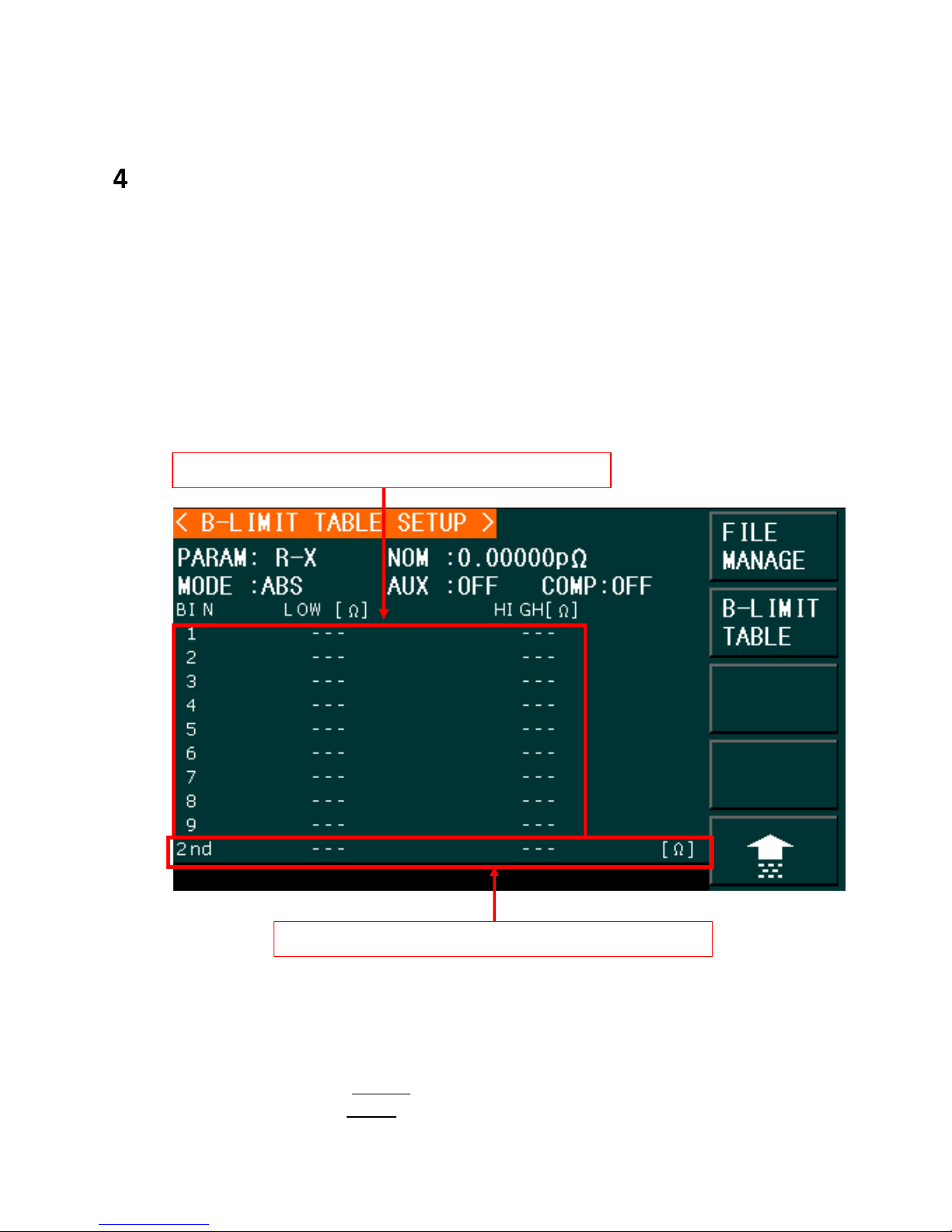
Low and High values for the Secondary Parameter
Low and High values for the Secondary Parameter
Limit Table Setup
The Limit Table Setup allows the user to set the parameters for the Bin Sorting Function. This
page allows the user to set the parameters for the built-in comparator. These LCR meters can
set nine bin limits of the primary parameters and one of the secondary parameters. The tested
result can be divided into up to ten bins (BIN 1 to BIN 9 and BIN OUT). If the primary parameter
of the DUT (device under test) is within the limit range from BIN1 to BIN9, but the secondary
parameter is out of the limit range, the DUT can be sorted into aux bin.
Press SETUP and then LIMIT TABLE to enter into the <LIMIT TABLE SETUP> page as the following
figure shown.
Figure 19 - Limit Table Setup
The following limit parameters of the Compare Function can only be set on <LIMIT TABLE
SETUP> page.
Measurement parameters (PARAM)
Compare function modes (MODE)
Find Quality Products Online at: sales@GlobalTestSupply.com
www.GlobalTestSupply.com
Page 53

Nominal value (NOM)
Auxiliary bin ON/OFF (AUX)
Comparator Function ON/OFF (COM)
High/Low limit of each bin (HIGH/LOW)
Measurement Parameters (PARAM)
For more details on how to set up Test Parameters and the available options go to section 3.2
Measurement Parameters.
Swap Parameters
This function will swap the primary and the secondary parameter in PARAM. For example, when
the measurement parameter is Cp-D, the swap parameter function can change the
measurement parameter to D-Cp.
Swapping Parameters
Follow the steps below to swap the primary and the secondary parameters.
1) Press SETUP.
2) Press LIMIT TABLE to enter into the <LIMIT TABLE SETUP> page
3) Move the cursor to PARAM, and the following soft key will be displayed.
SWAP PARAM
4) Press SWAP PARAM to swap the primary and the secondary parameters.
Compare Function Modes (MODE)
The compare function has two limit setup modes for the primary parameter as shown below in
Figure 20.
Tolerance mode
Under tolerance mode, set the deviation of the nominal value (NOM) as the compare
limit value. There are two deviation settings: percentage deviation, absolute deviation.
Sequential mode
Under sequential mode, the range of the test value is the compare limit value. The
compare limit value should be set in the order from smallest to largest.
53
Find Quality Products Online at: sales@GlobalTestSupply.com
www.GlobalTestSupply.com
Page 54
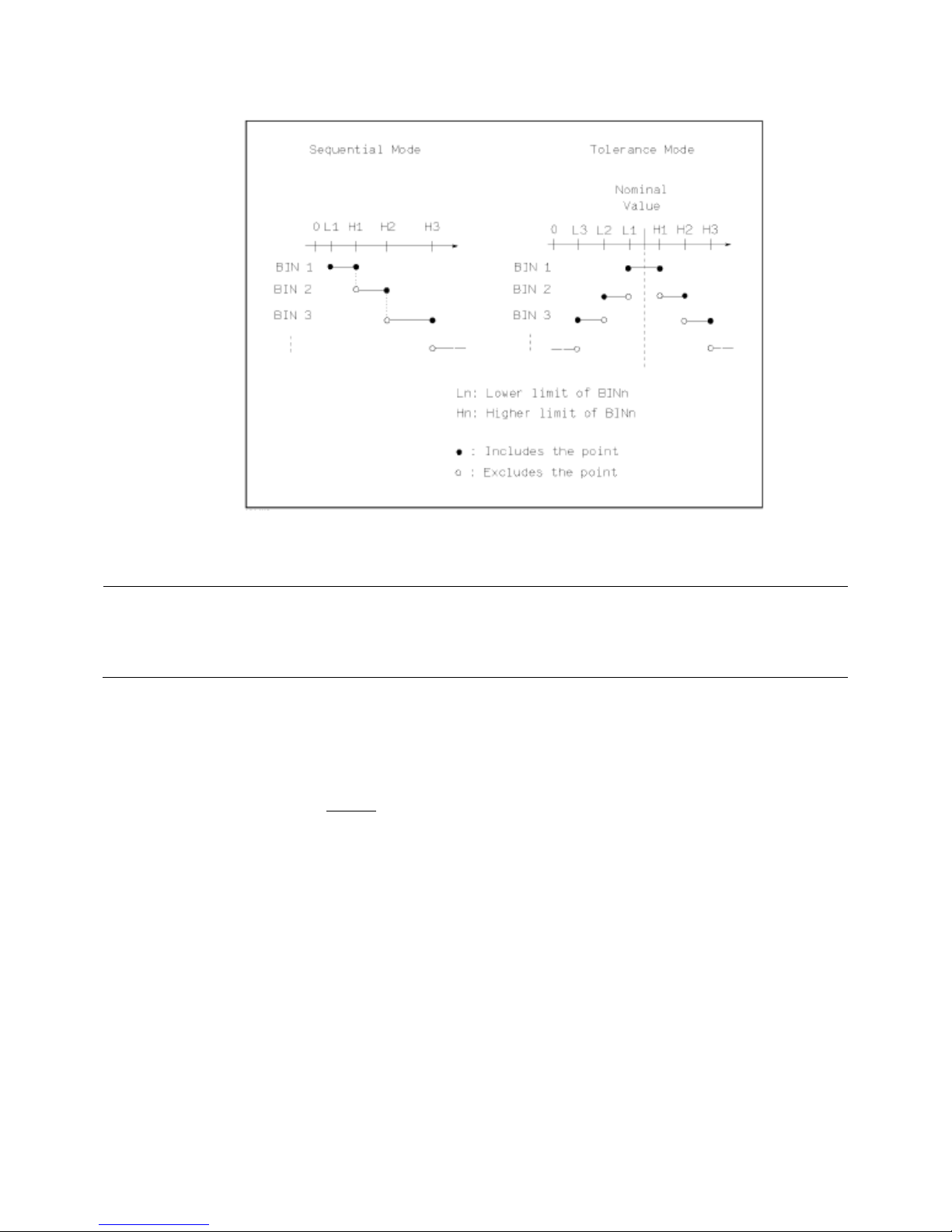
Figure 20 - Tolerance Mode and Sequential Mode
Note: When setting limit values of the tolerance mode, the error range should be set in the order from small
to large. If the error range of BIN1 is the largest one, then all DUT will sort into BIN 1.
Under tolerance mode, the low limit does not need to be smaller than the nominal value and the high
limit does not need to be larger than the nominal value. The limit range of each bin can be overlapped.
Setting Limit Modes
1) Press SETUP.
2) Press LIMIT TABLE to enter into the <LIMIT TABLE SETUP> page.
3) Move the cursor to MODE, and the following soft keys will be displayed:
o %TOL : Set percentage deviation tolerance (% TOL) as the limit mode.
o ABS TOL: Set absolute deviation tolerance (ABS TOL) as the limit mode.
o SEQ MODE: Sequential mode as the limit mode (SEQ)
4) Press the softkey to select the required the limit mode.
Tolerance Mode
When the tolerance mode is selected as the limit mode of the primary parameter, it is
necessary to set the nominal value. The nominal value can be any value within the display
range.
When the sequential mode is selected as the limit mode the primary parameter, the nominal
54
Find Quality Products Online at: sales@GlobalTestSupply.com
www.GlobalTestSupply.com
Page 55

value can be set, but it is optional.
Note: When the secondary parameter has the Low Limit set only, with the auxiliary bin set to ON, if the
primary parameter of the DUT is within the limit range and the secondary parameter is smaller than or
equal to its low limit, the DUT will be sorted into the auxiliary bin. When the secondary parameter has
the high limit set only, with the auxiliary bin set to ON, if the primary parameter of DUT is within the
limit range and the secondary parameter is larger than or equal to its high limit, the DUT will be sorted
into the auxiliary bin.
Setting the Nominal Value
1) Press SETUP.
2) Press LIMIT TABLE to enter into the <LIMIT TABLE SETUP> page.
3) Move the cursor to NOM.
4) Use numeric keys to input nominal value.
The following softkeys for the units of the nominal value will become available:
p, n, µ, and m
Press the → key to access additional units softkeys:
k, M, *1
Alternatively, enter a value directly using the numeric keypad, then press ENTER.
Auxiliary Bin (AUX)
Three conditions may occur during the secondary parameter sorting that will determine if the
Auxiliary Bin would be enabled:
On <LIMIT TABLE SETUP> page, no low/high limits of the secondary parameters have
been set.
On <LIMIT TABLE SETUP> page, the low/high limits of the secondary parameters have
been set but Aux function is set as OFF.
In this case, only those components that have a secondary parameter that is within the
specified limits will be sorted. If the secondary parameters are outside the limits set
and the corresponding primary parameters are within limit ranges, the components will
be sorted into BIN OUT.
On <LIMIT TABLE SETUP> page, the low/high limits of the secondary parameters have
been set and the Aux function is set as ON.
In this case, if the primary parameter is out of the limit range, it is sorted into BIN OUT.
If the primary parameter of DUT is within the limit range but its secondary parameter is
out of the limit range, the DUT will be sorted into the Aux bin.
Setting the Auxiliary Bin
1) Press the SETUP key. (Located between the MEAS and SYSTEM keys).
2) Press the LIMIT TABLE softkey.
Find Quality Products Online at: sales@GlobalTestSupply.com
www.GlobalTestSupply.com
55
Page 56

3) Using the arrow keys, move the cursor to AUX, the following soft keys will be
displayed.
ON
OFF
4) Press the ON softkey to enable the Aux Bin or, press OFF to turn the Aux Bin off.
Comparator Function (COMP)
Nine bin limits of the primary parameters and one bin limit of the secondary parameters can be
set. The tested results can be sorted into ten bins (BIN 1 to BIN 9 and BIN OUT). This function is
especially useful if the handler interface is used.
Enabling Compare Function
1) Press SETUP.
2) Press LIMIT TABLE to enter into the <LIMIT TABLE SETUP> page.
3) Move the cursor to COMP, the following soft keys will be displayed.
ON
OFF
4) Use above soft keys to enable (ON) or disable (OFF) the compare function.
High/Low Limits
The meter can set bin limits of nine primary parameters and one secondary parameter. The test
results can be sorted into ten bins at most (BIN 1 to BIN 9 and BIN OUT). The high/low limits of
primary parameters can be set in high limit and low limit of bins from BIN 1 to BIN 9. The limit
of the secondary parameter can be set in the HIGH and LOW fields at the bottom of the screen
in the field labeled “2nd” (2nd for Secondary Parameter) at the bottom of the Limit Table SETUP
screen, as detailed in Figure 19.
Operation steps for setting high/low limit
Follow this steps to set sorting limits:
1) Press SETUP.
2) Press LIMIT TABLE to enter into the <LIMIT TABLE SETUP> page
3) The primary parameter must be set in the <MEAS DISPLAY> page. Access this page by
pressing the MEAS key and follow the instructions detailed in the section: Selecting
56
Find Quality Products Online at: sales@GlobalTestSupply.com
www.GlobalTestSupply.com
Page 57

Primary and Secondary Parameters.
4) Use the cursor to set the nominal value in the NOM field.
5) Set the limit MODE of the primary parameter (as described in section 4.2 Compare ).
Repeat steps 6 to 9 if the Tolerance Mode was selected until the limits of BIN 9 are
input. The cursor will automatically move LOW of 2
nd
or repeat steps 10 to 14 if the
Sequential Mode was selected in Step 5.
6) User numeric keys to input low limit value in Low limit. After inputting the data, you
can select the units softkeys (p, n, µ, m, k, M, *1). After inputting limit value in LOW of
BIN 1, the low limit of BIN 1 will be automatically set to – (absolute limit) and the high
limit will be set to + (absolute limit).
7) The cursor will automatically move to LOW of BIN 2.
8) After inputting the low limit of the secondary parameter, the cursor will automatically
move to HIGH of 2nd.
9) Input the high limit of the secondary parameter.
10) In Low limit of BIN 1, use numeric keys to input the low limit, then select the units
softkeys (p, n, µ, m, k, M, *1).
11) After inputting the low limit of BIN 1, the cursor will automatically move to HIGH of BIN
1. Input the high limit of BIN 1.
12) The cursor will automatically move HIGH of BIN 2. In sequential mode, the low limit of
BIN 2 will be the high limit of BIN 1. Input the high limit of BIN 2.
13) Repeat step 9 until the high limit of BIN 9 is input. Then the cursor will automatically
move to LOW of 2nd. Input the low limit of the secondary parameter.
14) The cursor will automatically move to HIGH of 2
nd
. Input the high limit of the secondary
parameter.
57
Find Quality Products Online at: sales@GlobalTestSupply.com
www.GlobalTestSupply.com
Page 58

Bin Sorting Function
The following test conditions are displayed in the <BIN No. Disp> page. The following cannot be
set on this page but can be set in <MEAS SETUP> page.
Test function (FUNCA)
Test frequency (FREQ)
Test level (LEVEL)
Test range (RANG)
Test speed (SPEED)
DC BIAS
ON/OFF set state of OPEN, SHORT, LOAD (CORR)
To set these test conditions, refer to section 3.6 Measure Setup Menu.
Press the MEAS key and then the BIN NO. softkey to enter into <BIN NO. DISP> display page.
Figure 21 - Bin Sorting Function
Bin Count Display
The Bin Count Display page shows the count of the comparator function. It also provides the
information in the monitor fields for the Binning Function: PARAM, NOM, Bin Number, Bin
Sorting Limits (LOW/HIGH) and COUNT. This page displays only results (except for the COUNT
option).
58
Find Quality Products Online at: sales@GlobalTestSupply.com
www.GlobalTestSupply.com
Page 59

Figure 22 - Bin Count Display
Go to the <BIN COUNT DISP> page to see the count of each bin:
a) Press <MEAS DISP>
b) Pres the soft key BIN COUNT
The <BIN COUNT DISP> page allows the user to turn the Count function ON or OFF.
To enable the Count option:
a) While in the <BIN COUNT DISP> menu, press the down arrow in the cursors keys.
The softkeys ON or OFF will become available on the top right of the page.
b) Press ON to turn on the bin count.
PARAM
Parameter zone shows the “Function” parameter.
NOM.
Nominal parameter is the nominal value for bin compare function.
COUNT
This parameter shows the count value of the current bin.
59
Find Quality Products Online at: sales@GlobalTestSupply.com
www.GlobalTestSupply.com
Page 60

Setting the Bin Count Function
Execute the following operations to set the bin count function ON/OFF on <BIN COUNT
DISP> page.
1) On <BIN COUNT DISP> page, move the cursor to COUNT, the following soft keys will be
displayed.
ON
OFF
RESET
2) Press the soft key ON to turn on the count function.
3) Press the soft key OFF to turn off the count function.
4) Press the soft key RESET, and the following soft keys will be displayed.
YES
NO
5) Press the soft key YES to reset all bin counts to 0.
6) Press the soft key NO to cancel the reset operation.
BIN
This shows the bin number of the limit list. “2nd” means the secondary parameter limit.
HIGH/LOW
This shows the high and the low limits of the limit list.
AUX
This shows the count value of the auxiliary bin.
OUT
This shows the count value of the out bin.
60
Find Quality Products Online at: sales@GlobalTestSupply.com
www.GlobalTestSupply.com
Page 61

List Sweep Setup
1 3 4 5 6
2
1
The List Sweep Setup page allows the user to configure the List Sweep for up to 201
frequencies, test signal levels, DC bias voltage or DC current source.
On <LIST SWEEP SETUP> page, the following list sweep parameters can be set.
Mode (SEQ or STEP)
Sweep Parameters (frequency [Hz], level [V], level [A], bias [V], bias [A])
Sweep Test Points (Hz, V, A)
Limit Parameter (LMT)
High/Low Limit (HIGH, LOW)
Delay in Seconds (DELY)Clear Table (No.)
Figure 23 - List Sweep Setup
No.
When the cursor is set in this area, the soft keys will display “PREV PAGE” and “NEXT PAGE”.
By pressing any of these two soft keys the user will be able to navigate through the List
Sweep Display.
61
Find Quality Products Online at: sales@GlobalTestSupply.com
www.GlobalTestSupply.com
Page 62

Clear Table
NOTE: When the trigger mode is set to INT, sweep test modes of SEQ and STEP will not be controlled by
[TRIGGER]. When the trigger mode is set to MAN, [TRIGGER] can be used to trigger the list sweep
test.
2
3
This option clears the table completely.
Mode
The meter can automatically sweep up to 201 frequencies, test levels or DC bias. Two
sweep modes are available: SEQ and STEP. In SEQ mode, each press of the TRIGGER button
will initiate a test of all list sweep test points. In STEP mode, each press of the TRIGGER
button test one point at a time of the list sweep.
Setting the List Sweep Mode:
1) On the <LIST SWEEP DISP> page, move the cursor to MODE, and the following soft
keys will be displayed:
SEQ
STEP
2) Press SEQ to set the sweep mode as sequential sweep test mode.
3) Press STEP to set the sweep mode as single step sweep test mode.
Sweep Parameter
The sweep parameters can be: frequency [Hz], level [V], level [I], bias [V], and bias [I].
Setting the Measurement parameter
1) Press [SETUP] and then LIST SWEEP to enter into the <LIST SWEEP SETUP> menu.
2) Move the cursor the line following MODE. The following soft keys will be displayed:
FREQ [Hz] = Frequency as the sweep parameter.
LEVEL [V] = Voltage as the sweep parameter.
LEVEL [A] = Current as the sweep parameter.
BIAS [V] = DC bias voltage as the sweep parameter.
BIAS [A] = DC bias current as the sweep parameter.
3) Press one of above soft keys to select the list sweep parameter.
Sweep Test Points
Setting the Sweep Test Points
1) Press [SETUP] and then LIST SETUP to enter into the <LIST SWEEP SETUP> menu.
2) Using the cursor keys, move the cursors to a sweep point. The following options will
become available:
62
Find Quality Products Online at: sales@GlobalTestSupply.com
www.GlobalTestSupply.com
Page 63

Delete Line: Clears all the parameters of the line selected
4
Fill Linear: Fills the table linearly between the high value and low value.
Fill Log: Fills the table linearly between the high value and low value.
Prev Page: Returns to previous page.
Next Page: Moves onto the next page.
The user can enter the sweep test point values manually if Fill Linear or Fill Log is not
selected. The meter will perform the sweep only with the values entered in the field
below the Sweep Parameter (i.e. frequency [Hz], level [V], level [A], bias [V], bias [A]).
3) Enter a value in the Sweep Test Point (the field below the Sweep Parameter) using the
numeric keypad.
4) Using the softkeys, select the units available (Hz, kHz, and MHz).
Filling the Sweep Test Points Table Automatically:
There are two ways to fill the frequencies of the Sweep Table automatically:
1. Fill Linear
2. Fill Log
The user can set the first and last values where the sweep will take place. Then select
the option Fill Linear and the unit will automatically populate the 2nd to 9th frequency
steps.
For example, the user sets the 1 step to be 100 Hz. Second step to be 1000 Hz. Then
the option selected is Fill Linear.
The frequency values will populate as follows:
100 Hz, 200 Hz, 300 Hz, 400 Hz, 500 Hz, 600 Hz, 700 Hz, 800 Hz, 900 Hz and 1,000 Hz.
The spaces between points for the frequency sweep are even because the linear option
is selected.
Also, if the user does not set the low and high values, these LCR meters will
automatically fill the entire table, from the lowest frequency (20 Hz) to the highest
value (1 MHz) linearly or logarithmically, depending on the user selection.
Limit Parameters
The limit parameters are used to select which parameter, primary or secondary, is used to
compare with the high and low limits of the table. To select the primary parameters or
secondary parameters, select LMT A, or LMT B respectively. If this function is off, then the
measured values will not be compared against the low and high limits.
63
Find Quality Products Online at: sales@GlobalTestSupply.com
www.GlobalTestSupply.com
Page 64

High/Low Limits
5
6
This zone shows the high and the low limits of the limit list.
Delay
DLY parameter indicates the delay time from the last measurement of each sweep step to the
next sweep measurement.
64
Find Quality Products Online at: sales@GlobalTestSupply.com
www.GlobalTestSupply.com
Page 65
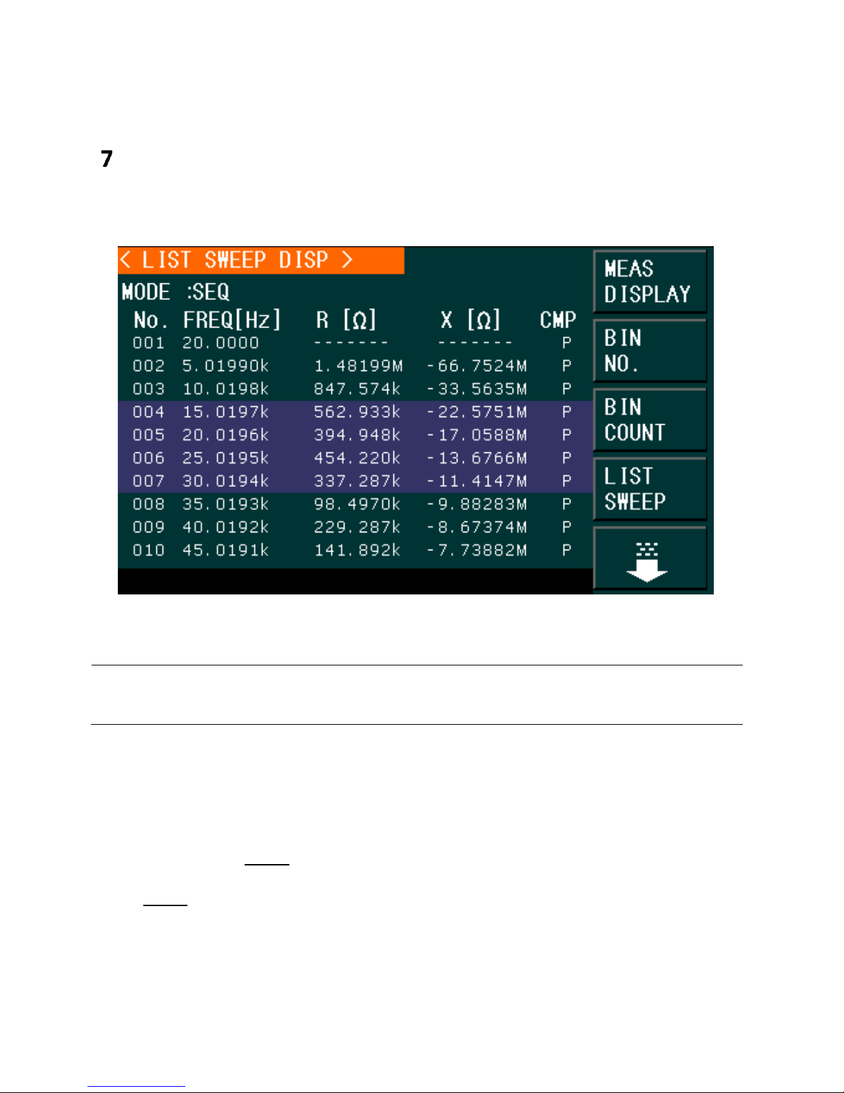
NOTE: When the trigger mode is set to INT, sweep test modes SEQ and STEP will not be controlled by the
TRIGGER key. When the trigger mode is set to MAN, [TRIGGER] can be used to trigger the list sweep
test and Reset to Stop the sweep and once stopped, it can also reset the sweep.
List Sweep Display
Press the menu key [MEAS DISPLAY] and then the soft key LIST SWEEP to enter into the <LIST
SWEEP DISP> page, shown below:
Figure 24 - List Sweep Setup
The test points will be automatically tested in scanning mode. Meanwhile, comparison will be
made between test results and limit values. In the process of list sweep test, “►” denotes the
current sweep test point.
Only the following control parameter can be set in <LIST SWEEP DISP>:
Sweep mode (MODE)
Select MODE on this page to set between SEQ (sequence) or STEP.
In SEQ mode, each press of TRIGGER key will trigger the meter to automatically test all
list sweep test points.
In STEP mode, each press of the TRIGGER key will trigger the meter to test one sweep
point.
Find Quality Products Online at: sales@GlobalTestSupply.com
www.GlobalTestSupply.com
Page 66

List Sweep Display Fields
No.
When the cursor is set in this area, the soft keys will display “PREV PAGE” and “NEXT PAGE”.
By pressing any of these two soft keys the user will be able to navigate through the List Sweep
Display.
FREQ (Hz)
This shows the swept frequencies.
R[:] X[:]
This displays the primary and secondary parameter measurements.
CMP (Compare)
This indicates the compare results of the swept points. L means the result is lower than the limit
and H is higher than the limit. A blank space indicates that it is within the limit.
Operation steps for setting the list sweep mode:
To set the sweep mode on the <LIST SWEEP DISP> page as SEQ or STEP:
1. On the < LIST SWEEP DISP > page, move the cursor to MODE, and the following
softkeys will be displayed:
SEQ
STEP
2. Press SEQ to set the sweep mode as sequential sweep test mode
Or
Press STEP to set the sweep mode as single step sweep test mode.
66
Find Quality Products Online at: sales@GlobalTestSupply.com
www.GlobalTestSupply.com
Page 67

Running a List Sweep Example
Manual trigger can be used to control when to start and stop sweep when trigger source is set
to manual (MAN). If the trigger source is set to internal trigger (INT), list sweep will run
indefinitely as soon as LIST SWEEP is pressed in the <MEAS DISP> page.
1. Press the setup button. The following screen will be displayed: <Measure Setup> and
navigate to the TRIG field. Press the softkey MAN to select Manual trigger.
2. Trigger has been set to manual. Press the SETUP button to exit to the previous menu:
3. Press the LIST SETUP softkey to the right of the screen. The following menu will be
displayed:
67
Find Quality Products Online at: sales@GlobalTestSupply.com
www.GlobalTestSupply.com
Page 68
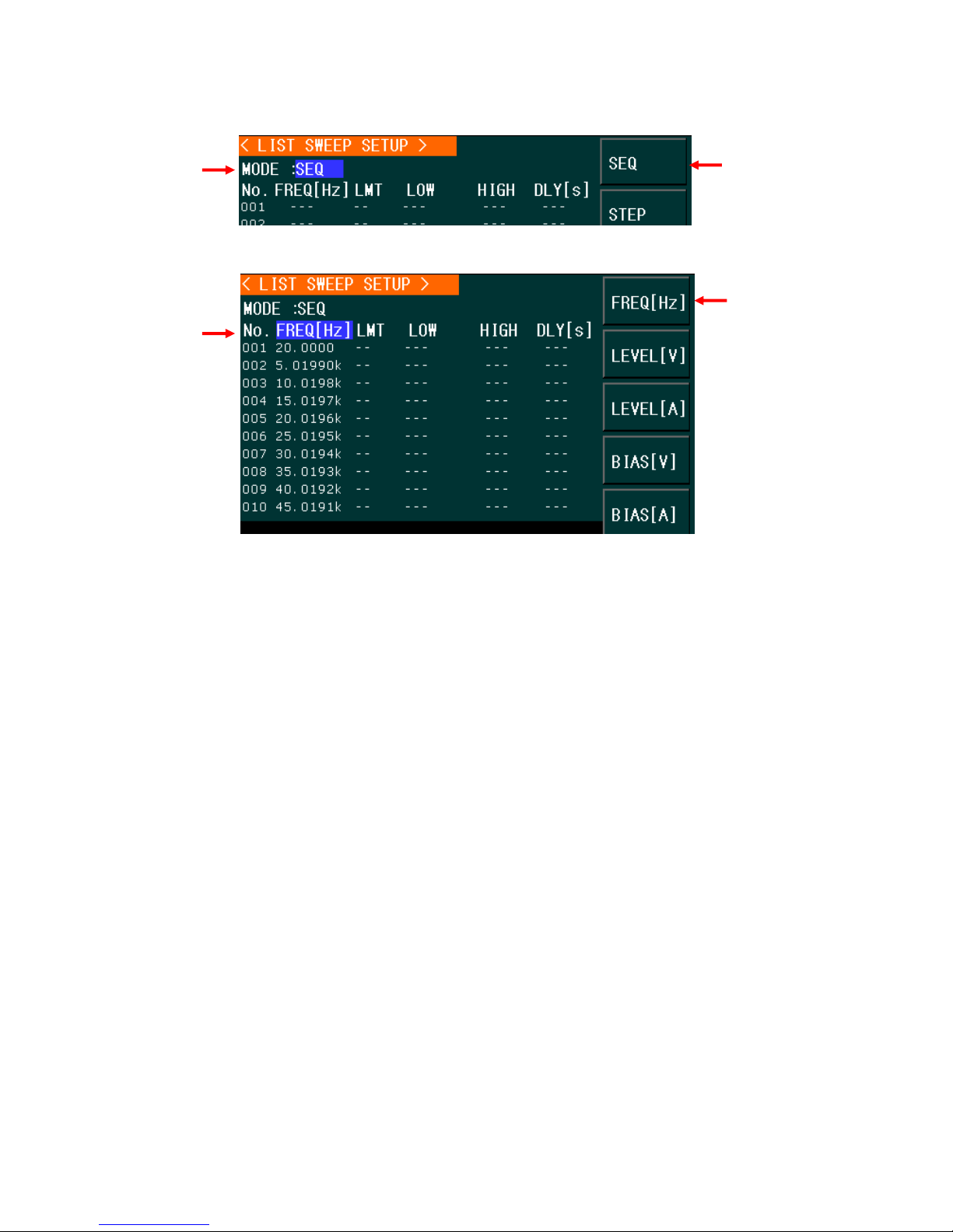
4. Using the cursors navigate to the MODE and select SEQ.
5. Using the cursors navigate to the parameter to be swept, select the FREQ [Hz] by
pressing the softkey.
6. Using the arrow keys, navigate to the frequency fields, then press Fill Linear.
68
Find Quality Products Online at: sales@GlobalTestSupply.com
www.GlobalTestSupply.com
Page 69
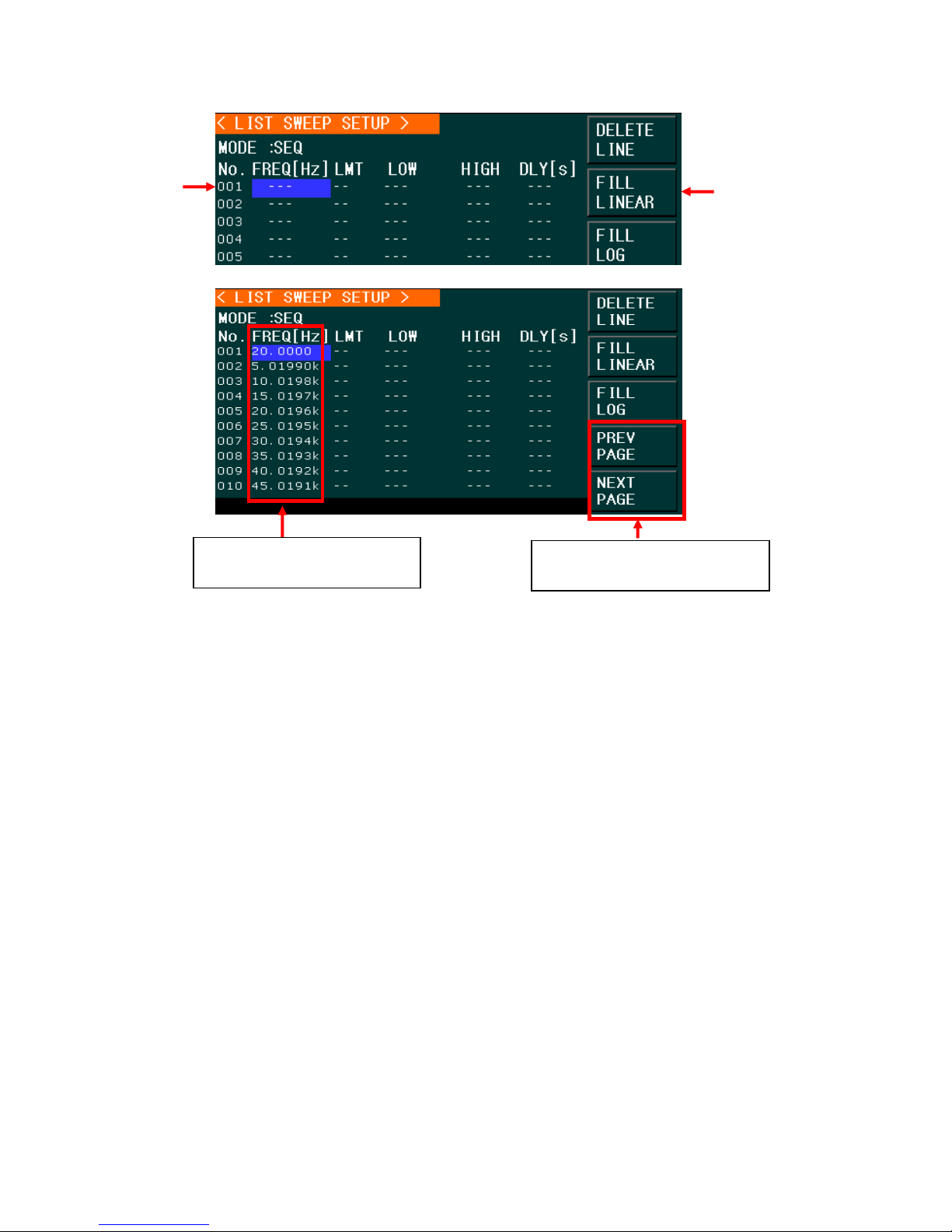
Frequencies filled linearly by
pressing the Fill Linear softkey.
Use these softkeys to navigate
through all the values.
7. Go to the main page by pressing the MEAS button and press the LIST SWEEP softkey.
69
Find Quality Products Online at: sales@GlobalTestSupply.com
www.GlobalTestSupply.com
Page 70
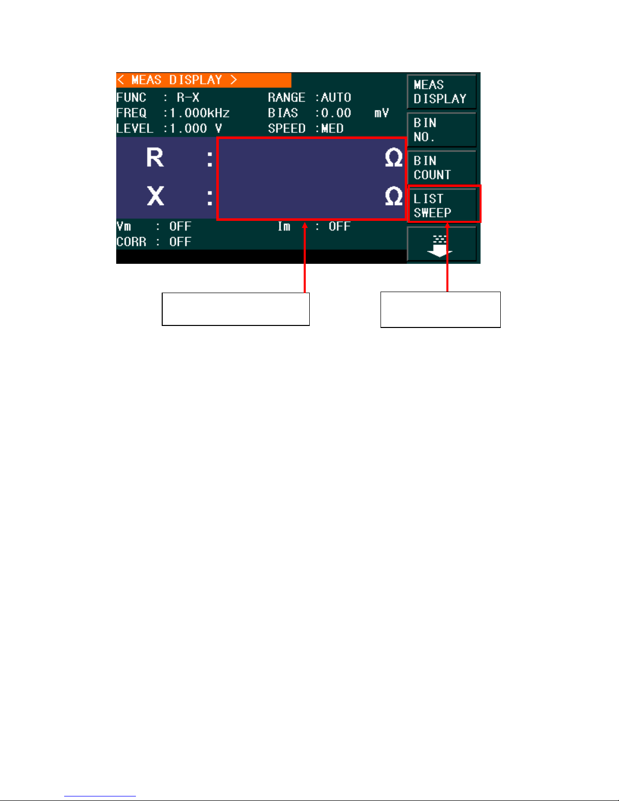
8. Press the [Trigger] button and the sweep will start. To stop, press the [Reset] button
No readings since the trigger
was set to manual.
Press to enter to the
List Sweep Display
once. To restart the sweep, press the [Reset] button twice.
The results of a frequency linear sweep of the primary and secondary parameters R and X are
shown below:
70
Find Quality Products Online at: sales@GlobalTestSupply.com
www.GlobalTestSupply.com
Page 71
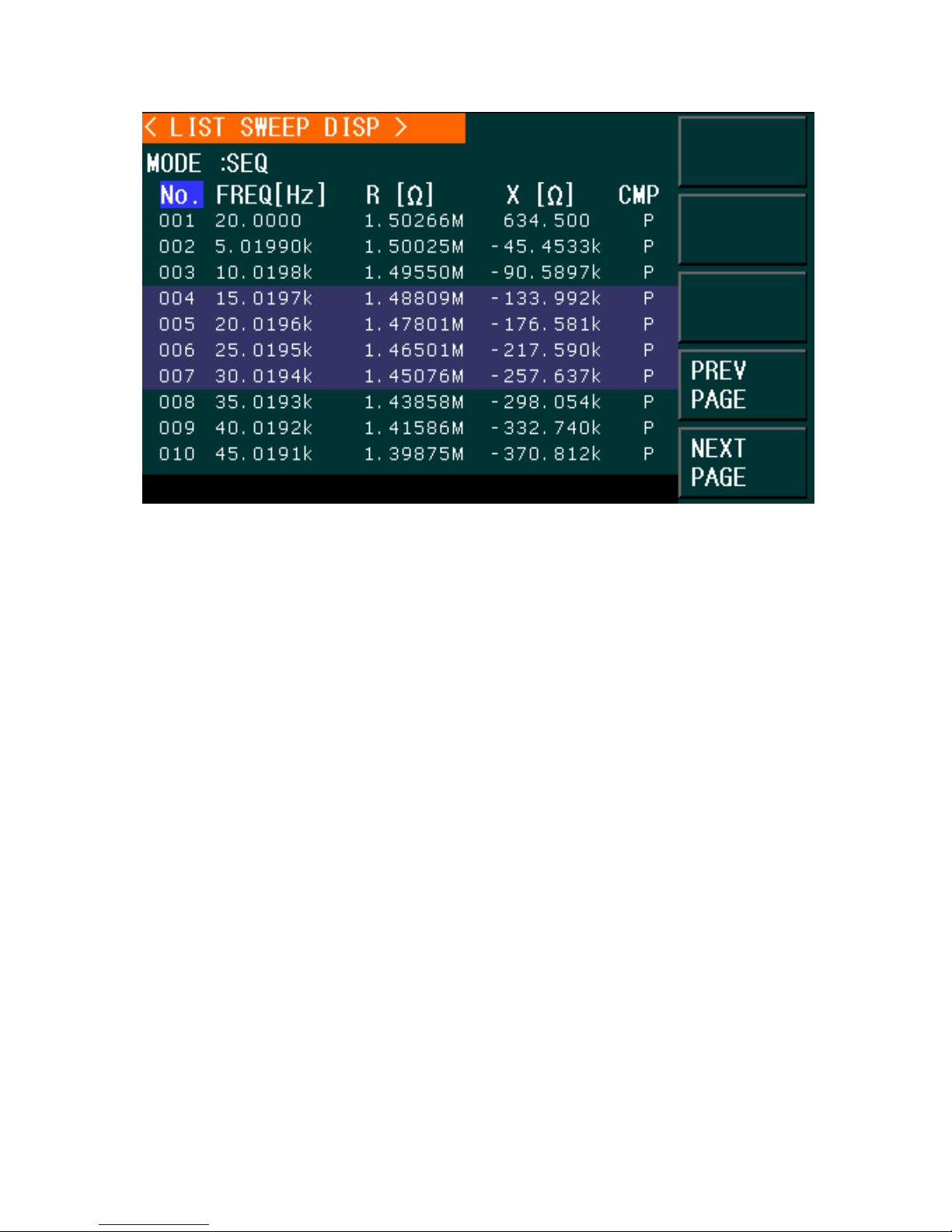
Figure 25 - Frequency Linear Sweep Results
71
Find Quality Products Online at: sales@GlobalTestSupply.com
www.GlobalTestSupply.com
Page 72
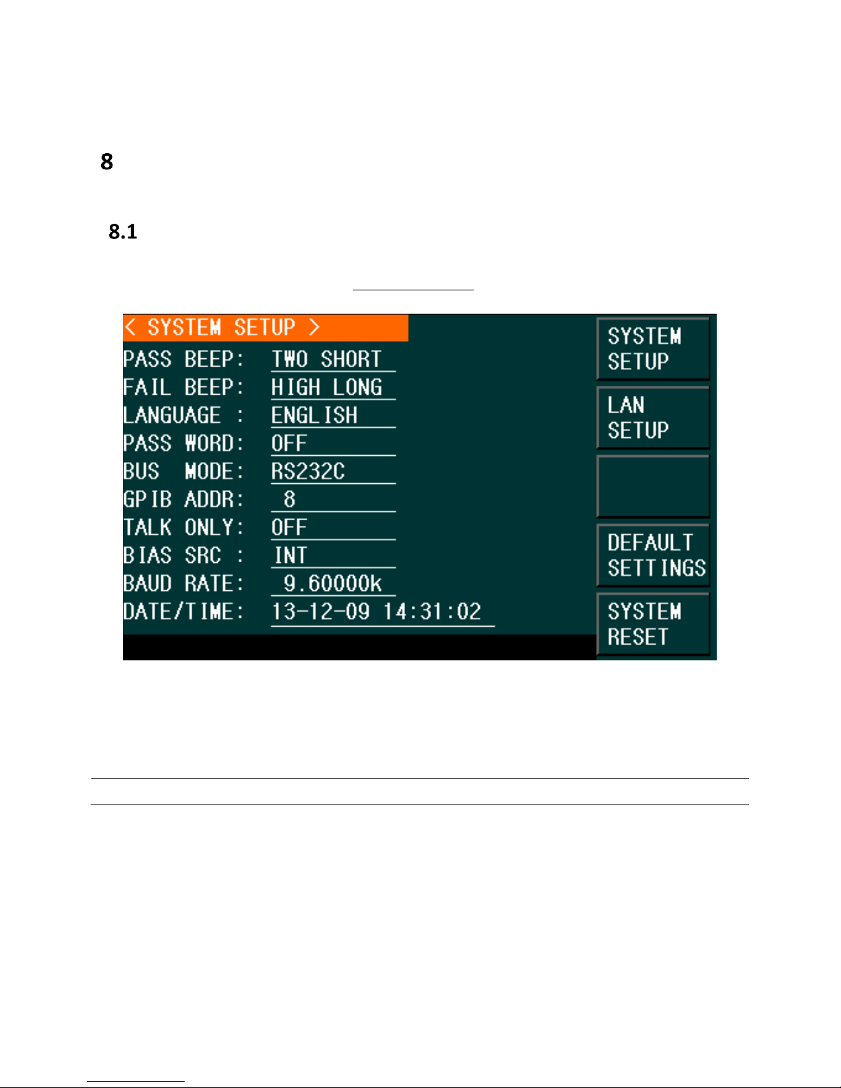
NOTE: Press LOG key to save the setup when finished to save the settings of this page.
System and File Management
System Setup
Press the System key to enter into the <SYSTEM SETUP> page shown below and modify any of
the options shown:
Figure 26 - System Setup
On this page, the following options can be setup: PASS beep, FAIL beep, language, PASS word,
bus mode, GPIB address, TALK only, Bias SRC, baud rate, date/time.
Pass Beep
Pass beep configures the beep when the measurement results pass the specified test
conditions.
Find Quality Products Online at: sales@GlobalTestSupply.com
www.GlobalTestSupply.com
Page 73

Operation steps for setting PASS BEEP
1) Move the cursor to PASS BEEP, and the following softkeys will be displayed.
HIGH LONG
This soft key selects a long, high tone beep.
HIGH SHORT
This soft key selects a short, high tone beep.
LOW LONG
This soft key selects a long, low tone beep.
TWO SHORT
This soft key selects two short, low tone beeps.
OFF
This soft key disables the pass beep function.
Fail Beep
Fail beep configures the beep when the measurement results do not pass the specified test
conditions.
1) Move the cursor to FAIL BEEP, and the following softkeys will be displayed.
HIGH LONG
This soft key selects a long, high tone beep.
HIGH SHORT
This soft key selects a short, high tone beep.
LOW LONG
This soft key selects a long, low tone beep.
TWO SHORT
This soft key selects two short, low tone beeps.
OFF
This soft key disables the pass beep function.
Language
This sets the display language of the instrument.
1) Move the cursor to LANGUAGE, and the following softkeys will be displayed.
ENGLISH
This softkey selects English as the display language.
CHINESE
This softkey selects Chinese as the display language.
73
Find Quality Products Online at: sales@GlobalTestSupply.com
www.GlobalTestSupply.com
Page 74

Password
Note: The instrument has a default password 0895.
This configures the password–protection mode.
1) Move the cursor to PASSWORD, and the following soft keys will be displayed.
OFF
This soft key disables the password protection mode.
Hold SYSTEM
This soft key enables the password protection mode including file protection and boot up
password.
Hold FILE
This soft key sets protection to user’s file.
MODIFY
This soft key is used to change the password. The operation steps are as follows:
Press MODIFY to input a new password (password must be 4 digits). A message prompt will
ask for the new password. Input the new password again to confirm changes.
Bus Mode
This mode is used to select RS-232, GPIB, LAN, USBTMC or USBCDC(virtual COM) remote
interface.
1) Move the cursor to BUS, and the following soft keys will be displayed.
RS-232C
GPIB
LAN
USBTMC
USBCDC
2) Use the above soft keys to select an interface for remote communication.
GPIB ADDR (895 only)
This configures the address of the instrument for remote communication via GPIB interface.
1) Move the cursor to GPIB ADDR, and the following soft keys will be displayed.
↑ (+)
a) This soft key is used to increase the GPIB address number.
↓ (-)
b) This soft key is used to decrease the GPIB address number.
74
Find Quality Products Online at: sales@GlobalTestSupply.com
www.GlobalTestSupply.com
Page 75

Talk Only
The Talk only function configures the instrument to send each measurement result to bus
through the remote interfaces. When it is ON, the instrument cannot be controlled by a remote
PC.
1) Move the cursor to TALK ONLY, the following soft keys will be displayed.
ON
OFF
2) Press ON to turn on the talk only function or OFF to turn off this function.
Bias SRC
Bias source is used to select the DC bias power. The instrument provides the bias source as
shown below:
INT mode
The standard DC bias voltage source is from -5 V to +5 V and the DC bias current source is
from -50 mA to +50mA.
Baud Rate
Baud rate is used select the baud rate for the RS-232 or USBCDC (virtual COM) interface.
Move the cursor to BAUD RATE, and the following soft keys will be displayed.
↑(+)
This soft key is used to increase the baud rate.
↓(-)
This soft key is used to decrease the baud rate.
The available baud rates are: 9600, 19200, 28800, 38400, 48000, 57600, and 115200.
Date/Time
The date format is: Year, Month, and Day.
The time format is 24 hrs. For example: 16:00:00 hrs. would be used instead of 4:00:00 pm.
75
Find Quality Products Online at: sales@GlobalTestSupply.com
www.GlobalTestSupply.com
Page 76

LAN Setup
NOTE: The unit must already be connected via Ethernet connection and the connected
network/router must be compatible to assign the correct parameters to the instrument.
Follow the instructions below to select the Ethernet interface and configure it for remote
operation.
1. Press the SYSTEM button and you will see the following options:
Figure 27 - LAN Setup
2. Press the LAN SETUP button.
3. To turn on the AUTO IP (or off) and the DCHP options, using the arrows, move the
cursor to the AUTO IP (or DCHP) field and using the soft menu keys press the ON
option. AUTO IP field will display whether that option is turned on or off.
4. Using the keypad and arrow keys to set the values required to establish communication
via Ethernet for IP Addr, Subnet Mask, Gateway, DNS Server1 and DNS server2.
5. Press any of the softkey buttons or any of the Menu Keys to exit the LAN SETUP page.
76
Find Quality Products Online at: sales@GlobalTestSupply.com
www.GlobalTestSupply.com
Page 77

Default Settings and System Reset
In the <System Setup> menu, the softkeys to the right of the screen allow the customer to set
the unit to Default Settings or perform a System Reset.
Press the Default Settings soft button to set all the settings of the System Setup menu
to their factory default values.
Press the System Reset soft button to reset the instrument.
File Management
The LCR meters have built-in non-volatile memory for storing and recalling instrument settings.
Most measurement menus, (i.e. Meas Display, List Sweep, etc.) have the File Manage option at
the bottom of the soft keys menu. To go to the page that has the File Manage option, press the
white down arrow soft key. Press FILE MANAGE soft key to enter into the LCR FILES LIST
(Internal memory) as shown below:
Figure 28 - File Management
77
Find Quality Products Online at: sales@GlobalTestSupply.com
www.GlobalTestSupply.com
Page 78

Setup file (*.STA)
40 user setup files (*.STA file) can be saved and recalled to and from the instrument. In
addition, users can use an external USB Flash drive (U-disk) to save/recall up to 500 setup files.
The settings stored in each Setup File are listed below:
Settings on <MEASURE SETUP> page
FUNCA
FREQ
LEVEL
RANGE
SPEED
DC BIAS
BIAS SRC
TRIGG
ALC
DELAY
Rsou
AVG
Vm
Cm
ISO
DEV A
DEV B
REF A
REF B
Settings on <BIN COUNT DISP> page
BIN COUNT (ON/OFF)
Settings on <LIMIT TAABLE SETUP> page
PARAM (swap parameter)
NOM (reference value)
MODE (%-TOL/ABS-TOL/SEQ-MODE)
AUX (ON/OFF)
COM (ON/OFF)
High and low limits of each bin
Settings on <List Sweep Setup> page
List Sweep Mode (SEQ/STEP)
List Sweep Parameter (Frequency/Level/Bias)
Test points of all sweep parameters
High and low limits of all test points, including limit parameters (LIMIT-DATA A/LIMIT-
DATA B)
Page format currently displayed
78
Find Quality Products Online at: sales@GlobalTestSupply.com
www.GlobalTestSupply.com
Page 79

Saving Settings to File
1. Configure the settings to be saved (see above list of settings saved for each page).
2. Move the cursor to FILE MANAGE from any of the pages with that menu available (i.e.
Meas Display, Measure Setup, etc.), and the following soft keys will be displayed.
LOAD
SAVE
DEL
FIND
COPY TO E:
3. In the file list (under the LCR ID label) move the cursor to the file-saved position or input
the file number directly.
Figure 29 - LCR Files List
4. Press STORE, the following soft keys will be displayed.
Yes
No
The following message will be displayed at the bottom of the screen:
“Are you sure you want to save to XXX” (file No.)
5. Press No to cancel the current save operation and return to step 2.
6. Press Yes, and “File name: ” will be displayed at the bottom of the screen.
7. Use numeric keys to input the current file name and press the ENTER key. The control
and setting parameters will then be saved into the file with this name.
79
Find Quality Products Online at: sales@GlobalTestSupply.com
www.GlobalTestSupply.com
Page 80

Load setting following these steps
1. Press FILE MANAGE, the LCR File List and the following soft keys will be displayed.
LOAD
SAVE
DEL
FIND
COPY TO E:
2. In the file list (under the LCR ID label, see Figure 29), move the cursor to the file-saved
position or input the file number directly.
3. Press LOAD, and the following soft keys will be displayed.
Yes
No
4. Press No to cancel the current load operation and return to step 1.
5. Press Yes to load the currently selected file. The LCR meter will return to the MEAS
DISPLAY page.
Copying a file to an U disk
1. Press FILE MANAGE, the file list and the following soft keys will be displayed.
LOAD
SAVE
DEL
FIND
COPY to E:
2. Move the cursor to the file to be copied and press [ENTER] to confirm.
3. Press COPY to E: to copy the file to the instrument.
4. While copying the file, the progress bar will appear to show the copy progress. When
completed, the progress bar will disappear.
Searching for an existing file
1. It is possible to access the LCR LIST FILE menu in these screens: MEAS DISPLAY or
MEASURE SETUP.
2. Press the down arrow to access the next page.
3. Press the FILE MENU to enter the <LCR FILES LIST> screen. This list displays the files
saved internally.
4. Use the [←] and [→] to view one by one page.
5. Press the soft key FIND. The screen will display the message: “Enter value or select”
80
Find Quality Products Online at: sales@GlobalTestSupply.com
www.GlobalTestSupply.com
Page 81

6. Input the name and then press the [ENTER] to search the target file or input the page
number and press the [ENTER] to search the file.
Save Screenshot
To take a screenshot of the LCD screen, follow these instructions:
1. Insert a USB drive into the front USB host port.
2. Press the [Copy] button.
3. The unit will automatically create a folder on the USB drive with the name PIC.
4. The screenshot will be saved to the folder mentioned above. The name assigned to the
screenshot will start at zero, but if there are other screenshots from this units in that
folder, it will assign the lowest value possible.
Save Measurements File
1. Configure the unit to measure a device (Func, Freq, Level, etc.)
2. Insert a USB drive into the USB host port of the unit.
3. Press the [Log] button to start saving measurements.
The 894/895 will create a folder labeled CSV inside the USB drive. Inside of it, it will also
create a .csv file and will start saving measurements to it. The name of the .csv file will
include the date and the file number saved in that date. (i.e. 0104_001, for the second file
save on January 4th).
4. Press the [Log] button to stop saving measurements.
USB Flash Driver Requirements
The meter features a USB host interface for connecting an external USB flash drive (U-Disk).
Below lists the requirements of the USB flash drive as supported by the instrument:
Meets the USB 1.0/1.1 standard
Capacity: 32MB/256MB/2GB/4GB
File format: FAT16, FAT32 (Format the USB memory from a Windows® operating
system)
81
Find Quality Products Online at: sales@GlobalTestSupply.com
www.GlobalTestSupply.com
Page 82
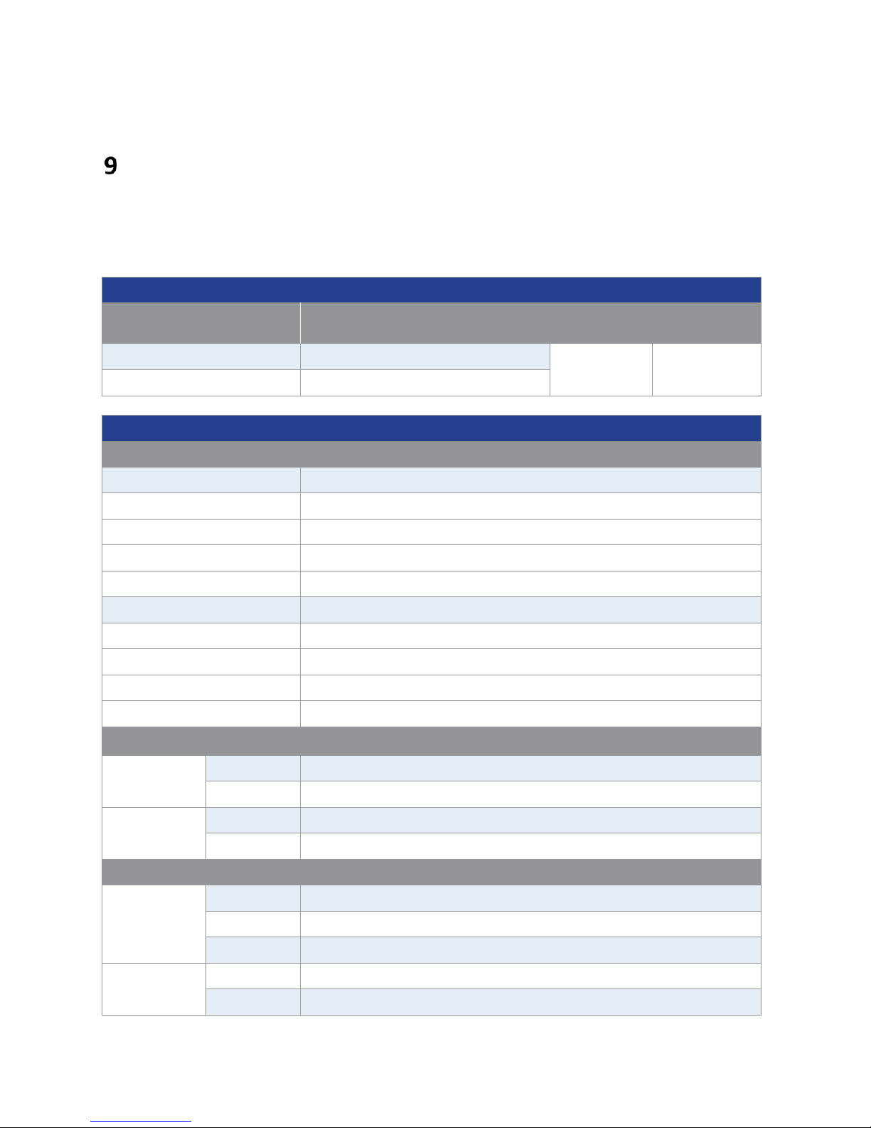
Test Signal Frequency
Model
Range
Minimum
resolution
Accuracy
894
20 Hz - 500 kHz
0.01 Hz
0.01 %
895
20 Hz - 1 MHz
Test Signal Levels
AC source (ALC* OFF)
Voltage Accuracy
10% x set voltage ± 2mV
Voltage Level
Resolution
5 mVrms - 100 mVrms
100 µVrms
100 mVrms - 1 Vrms
1 mVrms
1 Vrms - 2 Vrms
10 mVrms
Current Accuracy
10 % x set current ± 10 µA
Current Range
Impedance
166.7 µArms - 66.7 mArms
30 Ω
100.0 µArms - 40.0 mArms
50 Ω
50.0 µArms - 20.0 mArms
100 Ω
AC source (ALC* ON)1
Voltage
Range
10 mVrms – 1 Vrms
Accuracy
6 % x set voltage ± 2 mV
Current
Range
100 µArms - 10 mArms
Accuracy
6 % x set current ± 10 µA
DC bias source
Voltage
Range
-5 V to +5 V
Accuracy
1 % x set voltage ± 5 mV
Resolution
0.01 mV
Current
Range
-50 mA to +50 mA
Accuracy
1 % x set current ± 50 µA
Specifications
Note: All specifications apply to the unit after:
Temperature Stabilization time: 30 mins
Operating Temperature: 23 °C ± 5 °C
Specifications are subject to change without notice.
Find Quality Products Online at: sales@GlobalTestSupply.com
www.GlobalTestSupply.com
Page 83
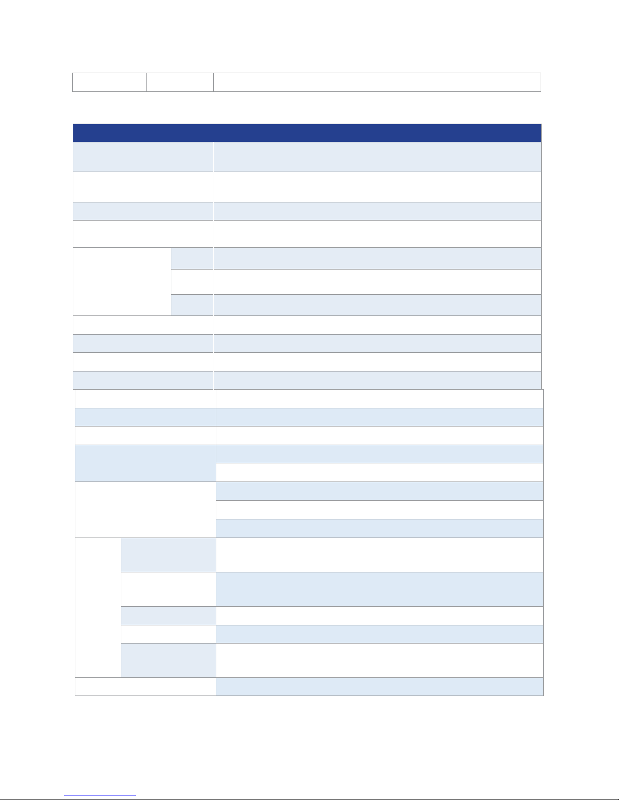
Resolution
0. 1 µA
*Auto Level Control
Measurements
Measurement
parameters
L, C, R, G, X, Z, Y, B, θ, Q, D, DCR
Transformer measurement
parameters2
L2A, L2B, N, 1/N, M
Basic accuracy
0.05 %
AC source Output impedance
(± 2%)
30 Ω, 50 Ω, 100 Ω
Typical
measurement time
(≥10 kHz)
(excluding display
refresh time)
Fast
13 ms / measurement
Medium
67 ms / measurement
Slow
187 ms / measurement
Equivalent circuit
Series, Parallel
Range mode
Auto, Hold
Averaging
1-255 measurements
Correction function
Open, Short and Load correction
Cable length compensation
0, 1, & 2 meters
Math operations
Direct reading, ∆ABS, ∆%
Trigger mode
Internal, Manual, External, Bus
Delay time setup
Time from trigger to start: 0 to 60 seconds
Resolution: 1 ms
Comparator (Bin sorting)
10-bin sorting, primary bins BIN1-BIN9 and OUT, secondary bin AUX
Bin counter: 0 to 999,999
PASS/FAIL indication via front panel LED or handler interface signal
List
sweep
201 sweep points
Sweep test frequency, test signal AC voltage, test signal AC current,
test signal DC bias voltage and test signal DC bias current
Measurement
parameters
Primary and secondary
Sweep modes
Linear or Logarithmic
Trigger mode
Sequential and Step
Comparator
One pair of lower and upper limits for primary or secondary
parameter (user selectable)
Internal non-volatile memory
Save / recall 40 setups
2: Requires optional fixture TL89T1
1: Resolution and impedance see AC source (ALC OFF) specification
Find Quality Products Online at: sales@GlobalTestSupply.com
www.GlobalTestSupply.com
83
Page 84
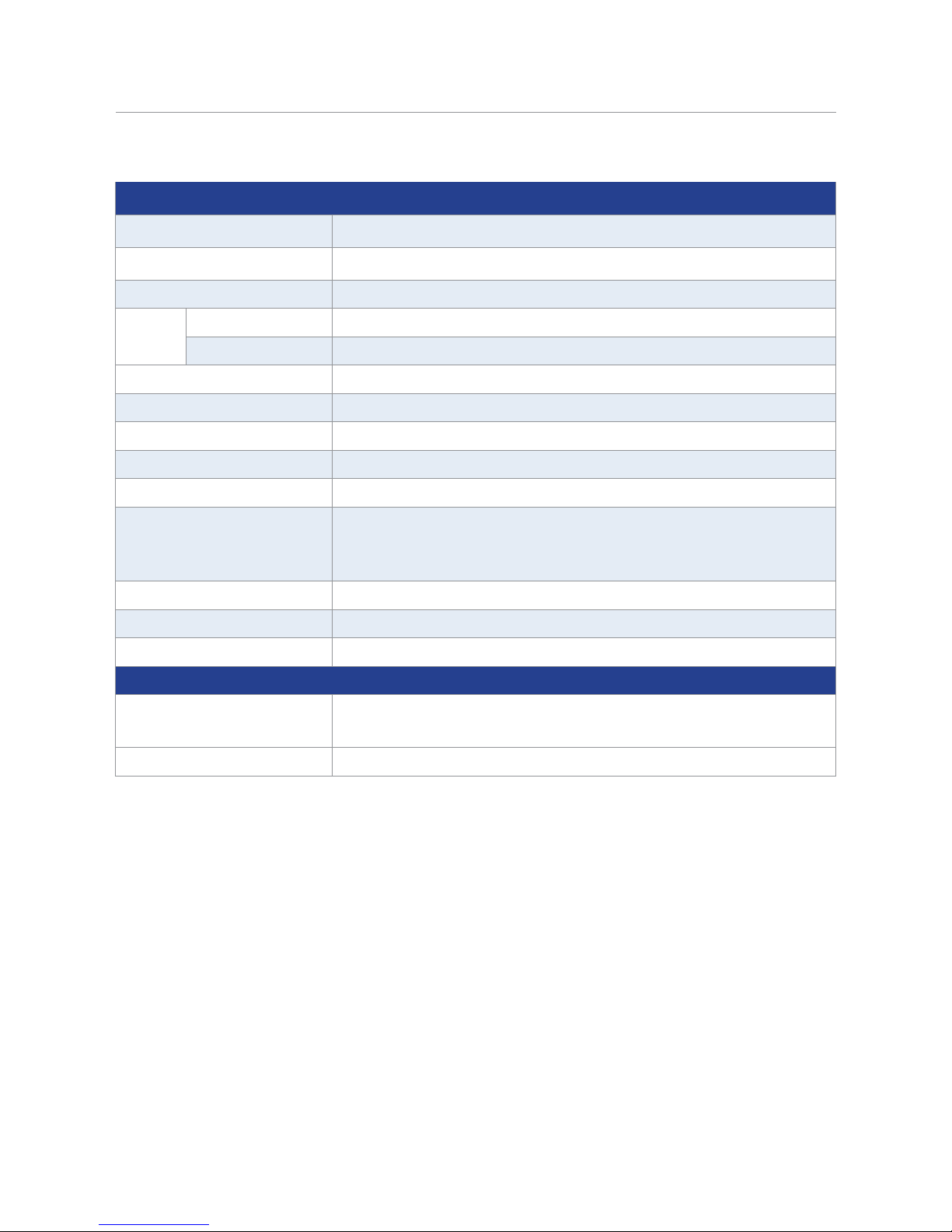
General
External USB memory
Save / recall setups, screenshots, measurements and sweep data logs
Remote interface
USB (USBTMC or virtual COM), RS232, LAN, GPIB (895 only)
Handler interface
36-pin connector
AC
input
Voltage
110/220 VAC ±10%
Frequency
47 – 63 Hz
Power consumption
Max. 80 VA
Operating temperature
0 °C to 40 °C
Storage temperature
-10 °C to 70 °C
Relative humidity
Up to 80%
Display
4.3” TFT color display
Dimensions (WxHxD)
Without bezel: 280 mm × 88 mm × 370 mm
(11.02“ x 3.46” x 14.56”)
With bezel: 369 mm × 108 mm × 408 mm (14.52” x 4.25” x 16.06”)
Weight
5 kg (11 lbs)
Safety
EN61010-1:2001, EU Low Voltage Directive 2006/95/EC
Electromagnetic Compatibility
Meets EMC Directive 2004/108/EC, EN61326-1:2006
Three-Year Warranty
Standard accessories
AC power cord, 4-wire Kelvin clip test lead, 4-terminal test fixture,
shorting bar, certificate of calibration, test report
Optional accessories
Transformer test fixture TL89T1
84
Find Quality Products Online at: sales@GlobalTestSupply.com
www.GlobalTestSupply.com
Page 85
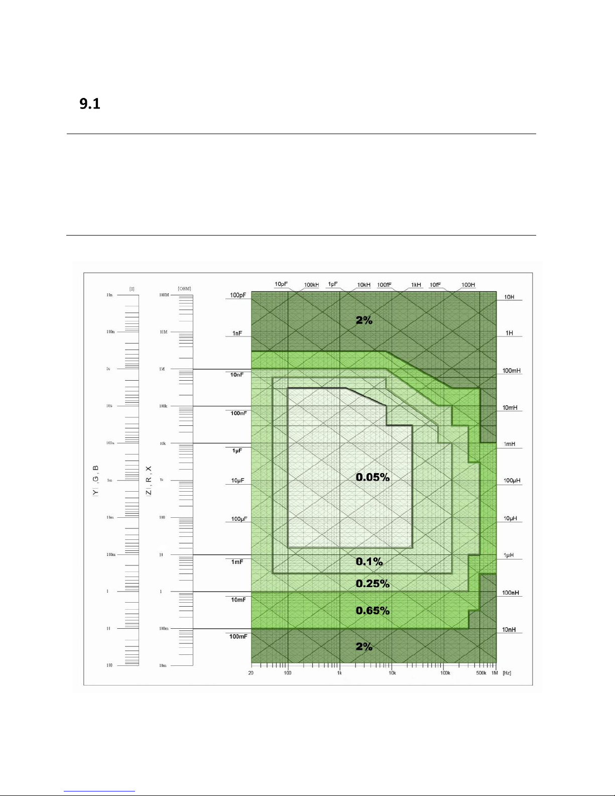
Note: The accuracies apply to the unit after:
Correction after warming up:
OPEN and SHORT
Test Cable Length:
0 m
Speed:
Slow/Medium
DC Bias:
Off
Range:
Auto
AC Test Signal Level =
0.5 to 1 Volt
Basic Accuracy A
Figure 30 - Basic Accuracy "A"
85
Find Quality Products Online at: sales@GlobalTestSupply.com
www.GlobalTestSupply.com
Page 86

Parameter
Condition
Measurement Accuracy Ae
L, C, X, B
Dx ≤ 0.1
Ae=Ae
R, G
Qx ≤ 0.1
Ae=Ae
L, C, X, B
Dx ≥ 0.1
Ae=Ae(
)
R, G
Qx ≥ 0.1
Ae=Ae(
)
Figure 30 depicts the basic accuracy using low or medium measurement speed. Whenever a
values falls on a range line use the larger accuracy value. Measurements tend to be less
accurate when high speed measurements are performed. When selecting fast measurements
speed, multiply by 2 the accuracy shown above.
Measurement Accuracy Ae
The Measurement Accuracy Ae includes the following: test voltage level, impedance of the DUT,
frequency used (directly calibrated or indirectly calibrated), cable length, temperature factor
and scan fixture modification error, in addition to the accuracy of the unit.
The accuracy Ae of Z, Y, L, C, R, X, G and B is expressed as:
Ae = ± [AL× A+(Ka+Kb+Kc)×100+ Kd +Kf]×Ke [%]
A: Measurement Accuracy (From Figure 30 )
AL: Level correction factor (Table 12)
Ka:Impedance rate factor (Table 13)
Kb:Impedance rate factor (Table 13)
Kc:Calibrated interpolating factor (Table 16)
Kd:Cable length factor (see Cable Length Factor: Kd)
Ke:Temperature factor (Table 18)
Kf:Scan fixture modification factor (no adding:Kf = 0, adding:Kf = 0.2)
Accuracy of G is only available in G-B combination.
Measurement Correction Factors
The basic accuracy A applies when the voltage test level range is between 500 mVrms to 1.0
Vrms. When the voltage test level is outside this range, select the value of AL according to Table
12 - Level Correction Factor (AL).
86
Find Quality Products Online at: sales@GlobalTestSupply.com
www.GlobalTestSupply.com
Page 87
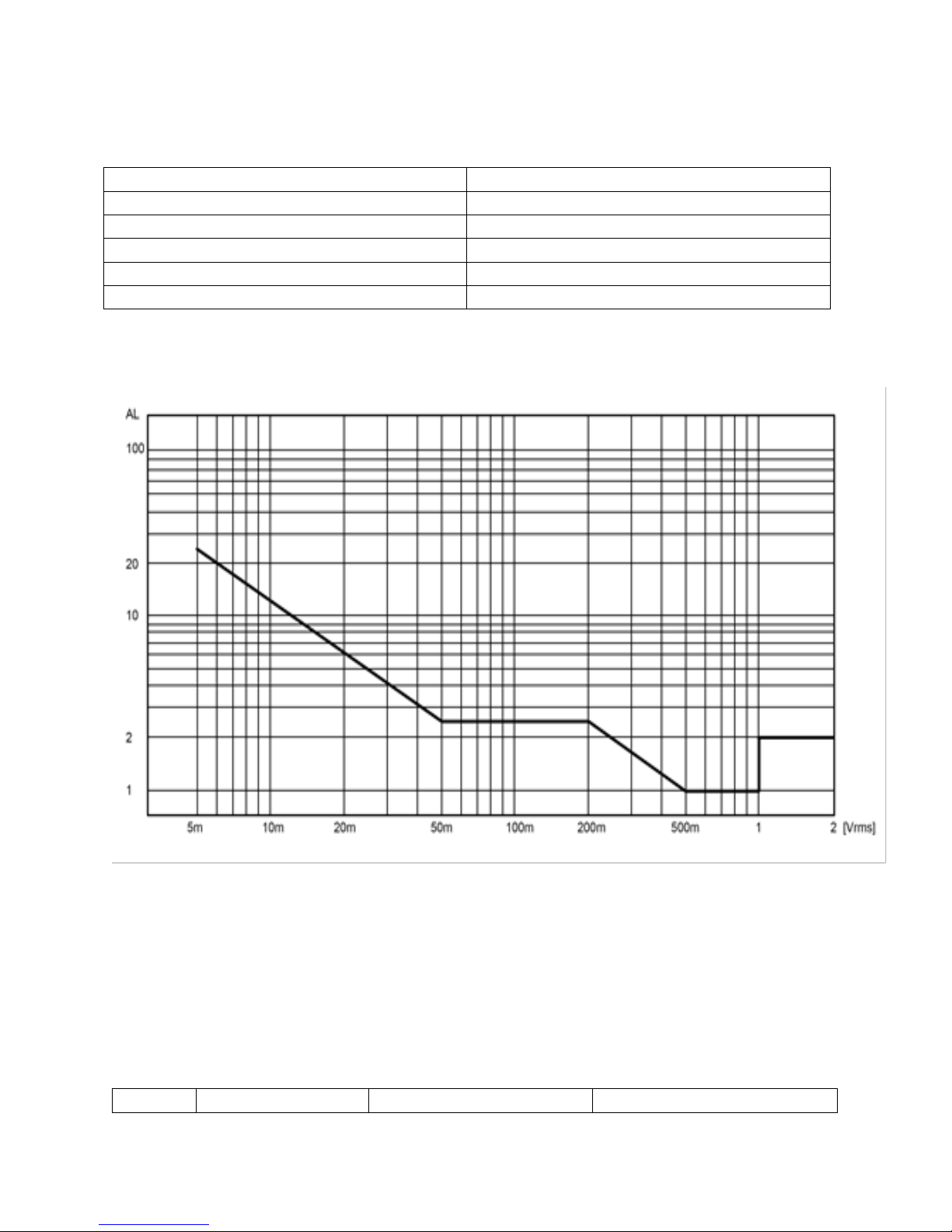
Level Correction Factor AL
Vs = Test signal voltage (Vrms)
Level Correction Factor (AL)
[5 m, 50 m]
2.5 × 50 mVrms / Vs
(50 m, 200 m)
2.5
(200 m, 500 m)
500 mVrms / Vs
(500 m, 1)
1
(1, 2]
2
Speed
Frequency
Ka
Kb
Table 12 - Level Correction Factor (AL)
The figure below shows the correction level factor (AL) graphically.
Figure 31 – Correction Level Factor – A
L
Impedance Rate Factors: Ka and Kb
Ka or Kb will be used depending on the impedance of the device under test. Only one of these
two factors will be used at a time. Each one has a compensation table that is used to adjust the
result of the calculation based on the length of the cable. The compensation for Ka should be
added to Ka and the compensation for Kb should be multiplied by Kb.
87
Find Quality Products Online at: sales@GlobalTestSupply.com
www.GlobalTestSupply.com
Page 88
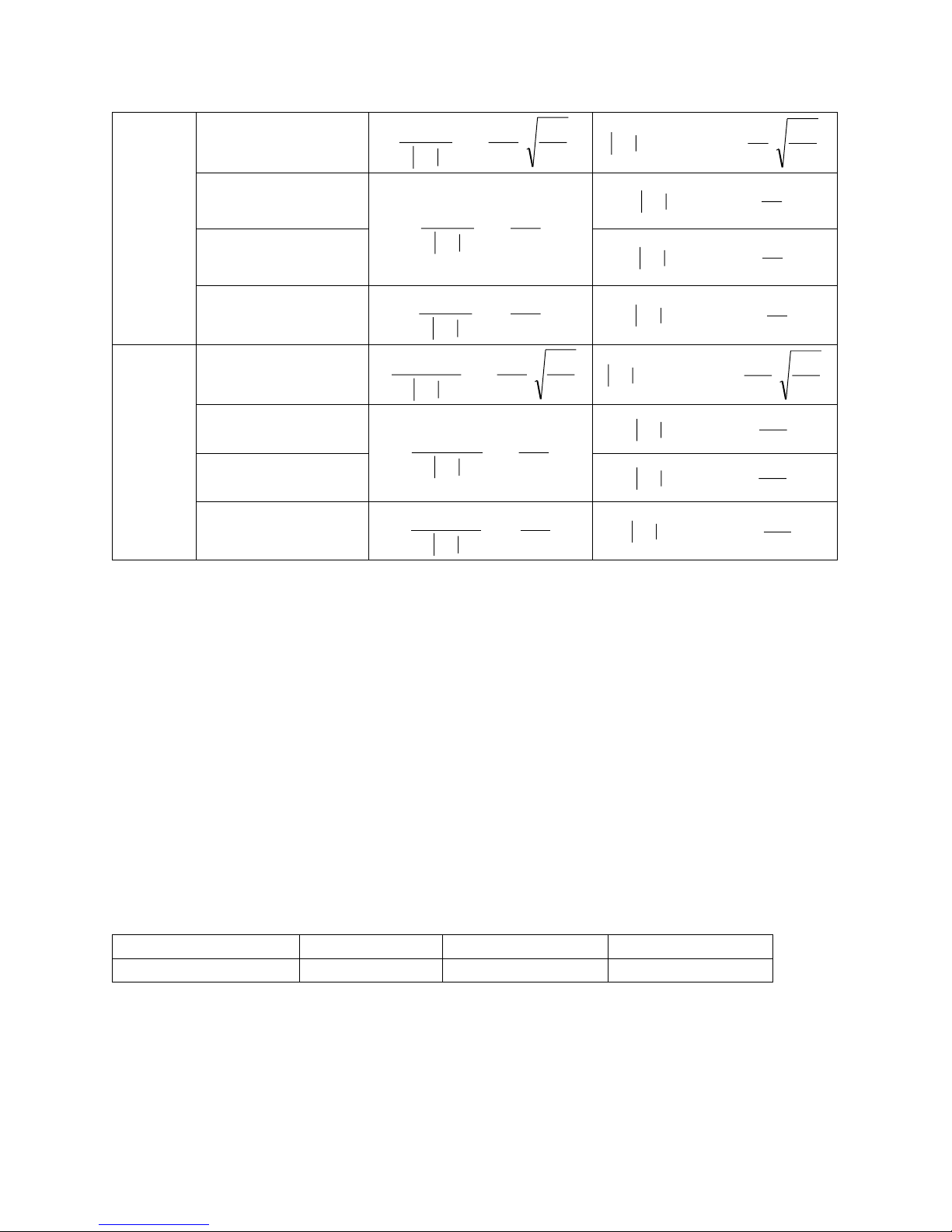
Medium
Slow
Fm 1.2 kHz
msm fVZ
100
)
200
1)(
101
(
3
ms
m
fV
Z
100
)
70
1)(103.0(
9
1.2 kHz fm ≤ 8 kHz
)
200
1)(
101
(
3
sm VZ
)
70
1)(101(
9
s
m
V
Z
8 kHz fm ≤ 150 kHz
)
70
1)(103(
9
s
m
V
Z
150 kHz fm ≤ 1 MHz
)
70
1)(1010(
9
s
m
V
Z
Fast
Fm 1.2 kHz
msm fVZ
100
)
400
1)(
105.2
(
3
ms
m
fV
Z
100
)
100
1)(106.0(
9
1.2 kHz fm ≤ 8 kHz
)
400
1)(
105.2
(
3
sm VZ
)
100
1)(102(
9
s
m
V
Z
8 kHz fm ≤ 150 kHz
)
100
1)(106(
9
s
m
V
Z
150 kHz fm ≤ 1 MHz
)
400
2)(
105.2
(
3
sm VZ
)
100
1)(1020(
9
s
m
V
Z
Table 13 - Impedance Rate Factors - Ka and Kb
Cable length L [m]
0 1 2
Ka
0
0.0005
0.0010
)
200
3)(
101
(
3
sm VZ
Where, fm is the test frequency and the unit is [Hz].
Zm= Measured Impedance of DUT
The unit of the tested impedance is [Ω].
The unit of the test signal voltage is [mV
rms
].
When the impedance is smaller than 500 Ω, Ka applies and Kb is not specified.
When the impedance is bigger than 500 Ω, Kb applies and Ka is not specified.
If the cable length of the text fixture is extended, apply the following compensation to Ka and
Kb:
Ka Compensation
Determine the Ka compensation and add it to the Ka value obtained from the table above, the
result will be the new Ka and it is this value what should be used in the accuracy calculation:
Table 14 - Extended Cable Length – Ka Compensation (Impendace Zm < 500 ohms)
88
Find Quality Products Online at: sales@GlobalTestSupply.com
www.GlobalTestSupply.com
Page 89

Kb Compensation
Cable length L [m]
0 1 2
Fm ≤ 100 kHz
1
1+5×fm
1+10×fm
100 kHz < fm ≤ 300 kHz
1
1+2×fm
1+4×fm
300 kHz < fm ≤ 1 MHz
1
1+0.5×fm
1+1×fm
Test frequency
Kc
Direct calibrated frequency
0
Other frequency
0.0003
20
25
30
40
50
60
80
[Hz]
100
120
150
200
250
300
400
500
600
800
[Hz]
1
1.2
1.5 2 2.5 3 4 5 6 8 [kHz]
10
12
15
20
25
30
40
50
60
80
[kHz]
100
120
150
200
250
300
400
500
600
800
[kHz]
1 [MHz]
Determine the Kb compensation and multiply it by the Kb value obtained from the table above,
the result will be the new Kb and it is this value what should be used in the accuracy calculation:
Table 15 - Cable Length Extended - Kb Compensation (Impendace Zm >500 ohms)
Where, fm is the test frequency and the unit is [MHz].
Calibrated Interpolating Factor: K
c
If the frequency used is any of the frequency stated in , Kc will be a “direct calibrated frequency”
and if it is any other frequency (not listed on the table), Kc will be considered “other frequency”
and the value of each type of frequency should be obtained from the table below ():
Table 16 - Calibrated Interpolating Factor Kc
Table 17 - Direct Calibrated Frequencies
Cable Length Factor: Kd
0.15%×(fm / 1MHz)2 × L
2
fm: test frequency [MHz]
L: test cable length [m], respectively 0m, 1m, 2m
When using scan, take the correction factor Kd as if the cable length is 2m.
89
Find Quality Products Online at: sales@GlobalTestSupply.com
www.GlobalTestSupply.com
Page 90

Temperature Factor: Ke
Temperature (℃)
0 - 18
18 - 28
28 - 40
Ke 4 1
4
100
eA
ex
ex
DQ
DQ
1
100
180 eA
xfL
2
1
Table 18 - Temperature Factor Ke
Accuracy of D
When Dx (tested value of D) ≤ 0.1, the accuracy of De is given by the formula below:
De =
When Dx > 0.1, De should be multiplied by (1+Dx).
Accuracy of Q
The accuracy of Q is given by the formula below:
Qe =
Where, Qx is the value of the tested Q.
De is the accuracy of D.
Above formula should be used when Qx×De < 1.
Accuracy of θ
The accuracy of θ is given by the formula below:
θe = [deg]
Accuracy of G
When Dx (tested value of D) ≤ 0.1, the accuracy of G is given by the formula below:
Ge = Bx×De [S]
Bx = 2πfCx for capacitance
Bx = for inductance
Where, Bx is the value of tested B with the unit [S].
Cx is the value of tested C with the unit [F].
Lx is the value of tested L with the unit [H].
De is the accuracy of D.
F is test frequency.
Note: The accuracy of G is only available in Cp-G and Lp-G combination
90
Find Quality Products Online at: sales@GlobalTestSupply.com
www.GlobalTestSupply.com
Page 91

ex
epx
DD
DR
xfC
2
1
Accuracy of Rp
When Dx (value of tested D) ≤ 0.1 the accuracy of Rp is given by the formula below:
Rp = [Ω]
Where, Rpx is the value of tested Rp with the unit [S].
Dx is the value of test D with the unit [F].
De is the accuracy of D.
Accuracy of Rs
When Dx (value of tested D) ≤0.1
The accuracy of Rs is given by the formula below:
Rse = Xx×De [Ω]
Xx = 2πfLx, for inductance.
Xx= , for capacitance.
Where, Xx is the value of test X with the unit [S].
Cx is the value of test C with the unit [F].
Lx is the value of test L with the unit [H].
De is the accuracy of D
F is test frequency
Accuracy of DCR
A (1+Rx/5MΩ+16mΩ/Rx)[%] ± 0.2 mΩ
When the instrument is in Middle and slow speed, A=0.25
In Fast speed, A=0.5
Where, Rx is the tested resistance.
Accuracy of leakage inductance Lk
Inductance L’s accuracy +0.2
91
Find Quality Products Online at: sales@GlobalTestSupply.com
www.GlobalTestSupply.com
Page 92

Accuracy Calculation Examples
Factor
Reason
AL=1
Test voltage level was 1 Volt, according to the Table 12 of manual the
correction factor for this voltage level is 1.
A = 0.05%
Using Figure 30 of the manual, the Test Measurement Accuracy (A)
of a 10.004 nF @ 1 KHz is 0.05% (intersection of 10 nF and 1 KHz on
the chart).
Ka= N/A
Zm= Impedance of the DUT = 15.9057 KOhms
Impedance of the device under test is bigger than 500 ohms. Ka=0.
Kb=
Use formula from Table 13 to find the
value of Kb.
Kb =
Kb is used because the impedance of DUT is bigger than 500 ohms.
Zm= Impedance of the DUT = 15.9057 KOhms
fm= 1 KHz (test frequency)
Vs= 1 (voltage test signal)
Kb=
Kb=0.00010713525
Cable Length =0. No Kb compensation (see Table 16)
Kc= 0
Test frequency 1 KHz = Direct Calibrated Frequency= 0
Example 1
Standard Capacitor Value: 10.004 nF @ 1 KHz
Measured value: 10.0046 nF @1 KHz
Dissipation Factor “D”: 0.00044
Test Signal Level: 1 V
Speed: Slow
Cable Length= 0 (no compensation needed)
D < 0.1 then: Ae is NOT multiplied by
Ae = Capacitance Accuracy = ± [(AL× A) + (Ka+Kb+Kc)× 100 + Kd + Kf] × Ke [%]
www.GlobalTestSupply.com
92
Find Quality Products Online at: sales@GlobalTestSupply.com
Page 93

See Table 16 and Table 17.
Kd= 0
L=0, therefore, Kd=0.
Ke= 1
Room temperature during test= 20o. Temperature Factor =1.
See Table 18.
Kf = 0
Fixture no available for this unit.
Factor
Reason
AL=1
Test voltage level was 1 Volt, according to the Table 12 of manual the
correction factor for this voltage level is 1.
A = 0.1%
Using Figure 30 of the manual, the Test Measurement Accuracy (A)
of a 10.00651 nF @ 1 KHz is 0.05% (intersection of 10 nF and 100
KHz on the chart).
Ae = ± [AL× A+(Ka+Kb+Kc)×100+ Kd]×Ke [%]
= 0.06074%=0.0006074
Finding the valid range: 0.06074% x 10.004 nF = 6.073977E-12
10.004nF + 6.073977E-12= 10.0105 nF
10.004nF - 6.073977E-12= 9.9983 nF
Valid range of measurements= [10.0105 nF, 9.9983 nF]
The 895 with measured 10.0044 nF which falls under the accepted range.
Example 2
Standard Capacitor Value: 9.995 nF, D=0.0002 @ 100 KHz
Measured value: C=10.0061nF @ 100 KHz
Dissipation Factor “D”: 0.00045
Test Signal Level: 1 V
Speed: Slow
Cable Length = 1 meter
D < 0.1 then: Ae is NOT multiplied by
Ae = Capacitance Accuracy = ± [(AL× A) + (Ka+Kb+Kc)× 100 + Kd] × Ke [%]
93
Find Quality Products Online at: sales@GlobalTestSupply.com
www.GlobalTestSupply.com
Page 94

Ka= 0.00053995862
Ka =
msm fVZ
100
)
200
1)(
101
(
3
Ka is chosen because impedance is less than 500 Ohms.
Zm= Impedance of the DUT = 159.069 Ohms
fm= 100 KHz (test frequency)
Vs= 1 (voltage test signal)
Ka =
) (1+200/1)(
Ka = 0.00003995862, but since we are using a 1 meter long testing
fixture, Ka needs to be compensated. (table 15)
Ka (new)= 0.00003995862+0.0005=0.00053995862
Kb= N/A
Kc= 0
Test frequency 100 KHz = Direct Calibrated Frequency= 0
See Table 16 and Table 17.
Kd= 0
L=1 meter, test cable lenght
Kd= 0.15%×(fm / 1MHz)2 × L2
fm: test frequency [MHz]
Kd= 0.0015x(100,000/1,000,000)x(1)2
Kd= 0.00015
Ke= 1
Room temperature during test= 20o. Temperature Factor =1.
See Table 18.
Kf = 0
Fixture no available for this unit.
Ae = ± [AL× A+(Ka+Kb+Kc)×100+ Kd + Kf]×Ke [%]
= 0.168995862%=0.00168995862
Finding the valid range: 0.168995862%x10.0061nF = 1.69098949E-11
10.0061nF + 1.69098949E-11= 10.02301nF
10.0061nF - 1.69098949E-11= 9.9891 nF
Valid range of measurements= [10.02301 nF, 9.9891 nF]
Find Quality Products Online at: sales@GlobalTestSupply.com
www.GlobalTestSupply.com
94
Page 95

The 895 with measured 10.0054 nF which falls under the accepted range.
Note how the first example is more accurate and the reason is because the test fixture does not
use a cable (cable length =0) and it is done using a frequency with a better accuracy for that
capacitor size.
95
Find Quality Products Online at: sales@GlobalTestSupply.com
www.GlobalTestSupply.com
Page 96
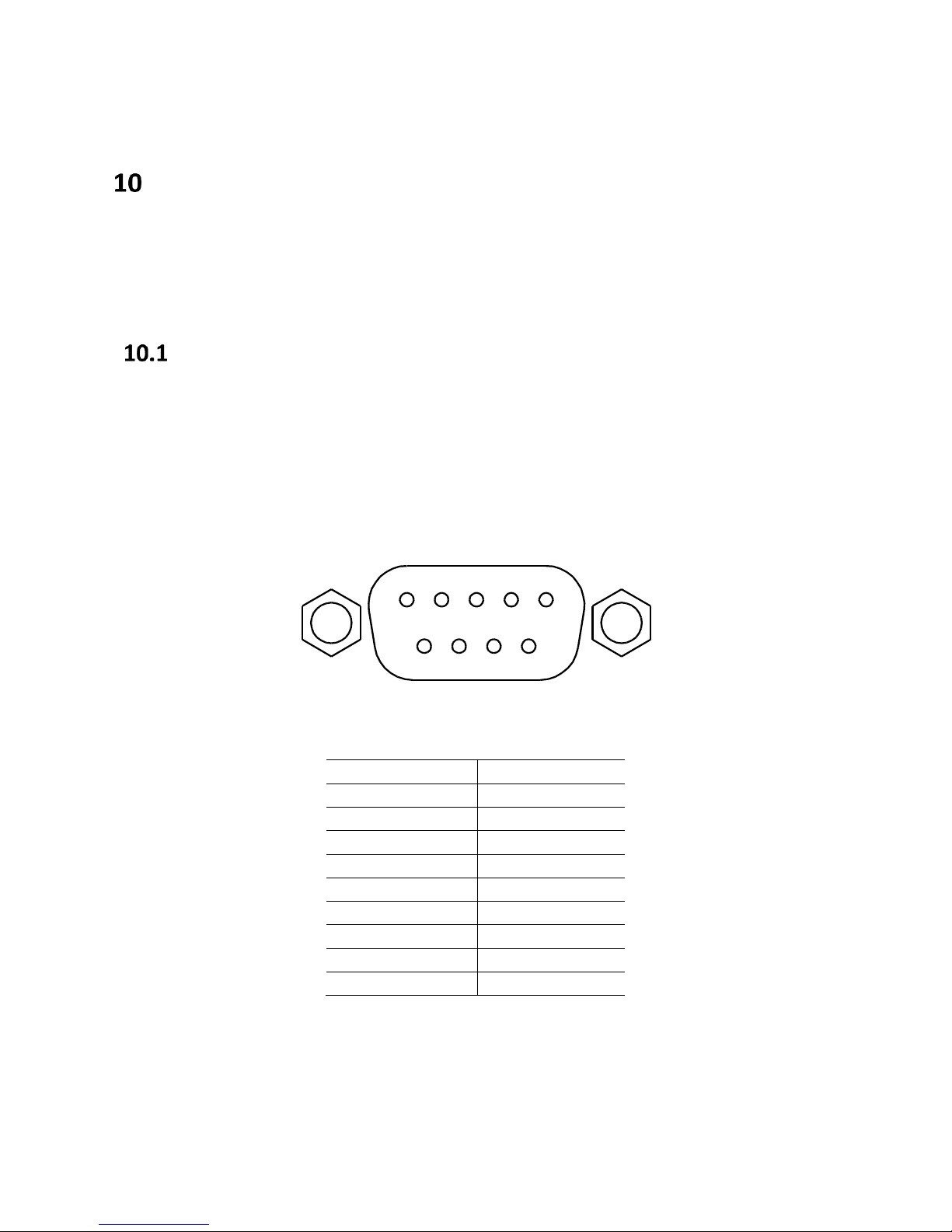
PIN
Description
1 - 2
Transmit Data
3
Receive Data
4 - 5
GND 6 -
7
CTS
8
RTS 9 -
1 2 3 4 5
6
7 8 9
Remote Interface
The instrument has RS232, USB (virtual COM), LAN, and GPIB (895 only) interfaces for remote
control. This chapter will describe how users can remotely operate the instrument and use SCPI
(Standard Commands for Programmable Instruments) commands via these interfaces.
Interface Configuration
For more information on how to set up this interface, refer to 8.1 , Bus Mode.
RS-232
For RS-232 connectivity, refer to the diagram below for the pinout information. The RS-232 is
labeled in the rear panel and it is a female DB-9 interface. Use a null modem or crossover cable
where pins 2 and 3 are reversed.
Find Quality Products Online at: sales@GlobalTestSupply.com
www.GlobalTestSupply.com
Page 97
Parameter
Description
Baud rate
9600, 19200, 28800, 38400, 48000, 57600, and 115200.
Parity and
data bit
None/8 bits, Even/8 bits, Odd/8 bits
Stop bit
1, 2
Flow control
None
Table 19 - RS-232C Settings
The RS-232 interface does not support hardware flow control (only transmit, receive,
and ground pins are used). The programmer should be aware of this limitation and
notice the command process time of the LCR meter. If the remote commands are
sent too fast to the LCR meter, the internal buffer may overrun and cause a
communication error. Therefore, adding a delay between commands may be
necessary to allow time for the meter to process.
The USB interface does not support hardware flow control (only transmit, receive,
and ground pins are used). The programmer should be aware of this limitation and
notice the command process time of the LCR meter. If the remote commands are
sent too fast to the LCR meter, the internal buffer may overrun and cause a
communication error. Therefore, adding a delay between commands may be
necessary to allow time for the meter to process.
USB (USBCDC - Virtual COM )
The standard USB port is a virtual COM port that can be used for remote communication. There
are no settings in the menu system for USB configuration. The settings are the same as the
settings for RS-232.
USBTMC
USB The standard USB port is a USBTMC-compliant port that can be used for remote
communication. There are no additional settings in the menu system for USB configuration. The
only requirement is that the USBTMC driver be installed. It is included when a VISA software is
installed on the computer. (We recommend using NI-VISA, which can be downloaded at
http://www.ni.com/visa/).
LAN (Ethernet)
The 894/895 can also be controlled via LAN interface. Refer to 8.1, LAN Setup for more
Find Quality Products Online at: sales@GlobalTestSupply.com
information.
97
www.GlobalTestSupply.com
Page 98

GPIB (895 Only)
The GPIB address of the LCR meter can be configured from 1-31. To communicate via GPIB,
connect a GPIB cable to the GPIB port at the back of the LCR meter. Refer 8.1, GPIB ADDR (895
only), for more information.
Remote Commands
The instrument supports some SCPI commands and some instrument specific commands. These
commands enable a computer to remotely communicate and control the instrument over any of
the supported remote interfaces: USBTMC, RS-232, LAN, and GPIB (895 only).
Refer to the programming manual for details, which can be downloaded from
www.bkprecision.com
98
Find Quality Products Online at: sales@GlobalTestSupply.com
www.GlobalTestSupply.com
Page 99
Handler Interface
Type of Signal
Characteristics
Output
Low effective optoelectronic isolation, open collector output
BIN comparator: Good/Not Good
List sweep comparator: IN/OUT for every sweep point and Pass/Fail
for all the devices compared
INDEX: AD Conversion ended
EOC: end of one test and comparison
Alarm: alarm for circuit interruption
Input
Optoelectronic isolation
External Trigger: Pulse width ≥ 1μS
Use of Handler will lock the keys on the front panel.
Note: The 894/895 uses a 36-pin connector.
The 894 and 895 are equipped with a Handler Interface. This interface allows users to fully
automate component sorting, inspection and quality control to increase the efficiency of sorting
process. The Handler Interface can output a signal to indicate the completion of a task and
allows an external trigger to trigger the instrument.
Technical description
The following table shows the description for 894/895 HANDLER.
Table 20 - Technical Description
Find Quality Products Online at: sales@GlobalTestSupply.com
www.GlobalTestSupply.com
Page 100

Handler Operation
Pin
Signal name
Description
1
2
3
4
5
6
7
8
9
10
11
/BIN1
/BIN2
/BIN3
/BIN4
/BIN5
/BIN6
/BIN7
/BIN8
/BIN9
/OUT
/AUX
BIN sorted result
/BIN (BIN number) output are all open collector
outputs.
12
13
/EXT.TRIG
External trigger: when the trigger mode is EXT.TRIG,
the 894/895 will be triggered by the positive-edge
pulse signal in this pin.
14
15
EXT.DCV2
External DC voltage 2:
The DC provider pin for the optoelectronic coupling
signal (/EXT_TRIG, /Key Lock, /ALARM, /INDEX, /EOM)
The definition for the signal line
The Handler interface has 3 signal lines: comparison output, control output and control
input. The output signals for the BIN comparison or list sweep comparison functions are
detailed below:
Comparison Signal Lines
Comparison output signal
BIN1-BIN9
AUX
OUT
PHI (the main parameter is bigger than the high limit)
PLO (the main parameter is low)
SREJ (The test result is outside the valid range)
Control output signal
INDEX (Analog test finished signal)
EOM (Test ended and the compared data effective)
ALARM (Circuit interruption)
Control input signal
EXT.TRIG (External trigger signal)
Keylock (Key lock).
The Comparison signal distribution for the pins is described in Table 2:
Find Quality Products Online at: sales@GlobalTestSupply.com
www.GlobalTestSupply.com
100
 Loading...