

Model 830C, 890C
Dual Display
INSTRUCTION MANUAL
99 Washington Street
Melrose, MA 02176
Phone 781-665-1400
Toll Free 1-800-517-8431
Visit us at www.TestEquipmentDepot.com
Capacitance Met er

Test Equipment Depot - 800.517.8431 -
99 Washington Street Melrose, MA 02176
- FAX 781.665.0780 - TestEquipmentDepot.com

Safety Summary
The following safety precautions apply to both
operating and maintenance personnel and
must be observed during all phases of
operation, service, and repair of this
instrument.
DO NOT OPERATE IN AN EXPLOSIVE
ATMOSPHERE
Do not operate the instrument in the presence
of flammable gases or fumes. Operation of
any electrical instrument in such an
environment constitutes a definite safety
hazard.
KEEP AWAY FROM LIVE CIRCUITS
Instrument covers must not be removed by
operating personnel. Component
replacement and internal adjustments must be
made by qualified maintenance personnel.
DO NOT SUBSTITUTE PARTS OR MODIFY
THE INSTRUMENT
Do not install substitute parts or perform any
unauthorized modifications to this instrument.
Return the instrument to B&K Precisi on for
1

service and repair to ensure that safety
features are maintained.
WARNINGS AND CAUTIONS
WARNING and CAUTION statements, such
as the following examples, denote a hazard
and appear throughout this manual. Follow all
instructions contained in these statements.
A WARNING statement calls attention to an
operating procedure, practice, or condition,
which, if not followed correctly, could result in
injury or death to personnel.
A CAUTION statement calls attention to an
operating procedure, practice, or condition,
which, if not followed correctly, could result in
damage to or destruction of part or all of the
product.
2

SAFETY GUIDELINES
To ensure that you use this device safely,
follow the safety guidelines listed below:
This meter is for indoor use, altitude up to
2,000 m.
The warnings and precautions should be
read and well understood before the
instrument is used.
When measuring in-circuit components, first
de-energize the circuits before connecting to
the test leads.
Never attempt to measure voltage with this
instrument.
Do not use the device if it appears damaged
in form.
Inspect the leads for damaged insulation or
exposed metal. Replace damaged leads if
necessary.
Disconnect power and discharge all
capacitors prior to testing.
The meter is safety-certified in compliance
with EN61010 (IEC 1010-1) Installation
3

Category II (CAT. II) 50 V, Pollution Degree
2 environment.
Use the meter only as specified in this
manual. Otherwise, the protection provided
by the meter may be impaired.
The power for the meter is supplied with a
single standard 9V battery. It can also
operate from AC line using a 12V AC to DC
adaptor. If a power adaptor is selected,
please be sure to use one with correct AC
line input voltage and fulfills the safety
requirements of a relevant IEC standard.
Use only battery specified by the meter. See
“
Installing Battery
” section for details.
4
outside is negative (-)
Safety Symbols
This symbol is a warning and
indicates that the user should refer to
the operating instructions located in
the manual.
DC Current
Indicates inside pin is positive (+),
Compliance Statements
Disposal of Old Electrical & Electronic Equipment
(Applicable in the European
Union and other European countries with separate
collection systems)
5
This product is subject
Council of the European
equipment (WEEE) , and
requirements.
to Directive 2002/96/EC
of the European
Parliament and the
Union on waste
electrical and electronic
in jurisdictions
adopting that Directive,
is marked as being put
on the market after
August 13, 2005, and
should not be disposed
of as unsorted
municipal waste. Please
utilize your local WEEE
collection
facilities in the
disposition of this
product and otherwise
observe all applicable
6

Storage Humidity
0 – 80% R.H.
Storage Environment
-20 °C to +50 °C
Pollution degree
Pollution degree 2
Environmental Con diti ons
Operating Environment
0 °C to 40 °C
7

TABLE OF CONTENTS
SAFETY GUIDELINES ............................................... 3
INTRODUCTION ....................................................... 11
PACKAGE CONTENTS ........................................... 13
FRONT PANEL OVERVIEW .................................... 14
Front Panel Display Descriptions .................................. 15
Front Panel Buttons ...................................................... 16
LCD DISPLAY OVERVIEW ...................................... 18
LCD Display Descriptions ............................................. 18
PUSH BUTTONS OVERVIEW ................................. 20
POWERING INSTRUMENT ..................................... 22
Installing Battery ........................................................... 22
Connecting External Power Source .............................. 24
Low Battery Indication .................................................. 27
Backlit Display .............................................................. 27
POWER ON OPTIONS ............................................. 29
Reset HI/LO Limits ........................................................ 29
View Firmware Version ................................................. 30
Setup Menu .................................................................. 30
SETUP OPTIONS ..................................................... 31
8
Test Equipment Depot - 800.517.8431 -
99 Washington Street Melrose, MA 02176
- FAX 781.665.0780 - TestEquipmentDepot.com

Baud Rate (bAUd) ........................................................ 33
Parity (PArt) .................................................................. 35
Data Bits (Data) ............................................................ 36
Echo (ECHO) ................................................................ 37
Print Only (Prnt) ............................................................ 38
Key Beeper (bEEP) ...................................................... 39
Lock Buttons (LbUt) ...................................................... 40
Auto Power Off (AOFF)................................................. 41
Backlit Display Time (bLIt) ............................................ 44
Bright Level Off State (bOFF) ....................................... 44
Brightness Level On State (bON) ................................. 47
Reset to Default (dEFA) ................................................ 49
OPERATION INSTRUCTIONS ................................. 51
Data Hold/Trigger Hold ................................................. 51
Static Recording ........................................................... 53
Relative Mode ............................................................... 57
Tolerance ...................................................................... 60
Compare Mode ............................................................. 65
REMOTE COMMUNICATION .................................. 75
Connecting Instrument to PC ........................................ 75
USB (Virtual COM) Configuration ................................. 76
9

Remote Mode ............................................................... 76
Command Protocols ..................................................... 77
MEASUREMENT TIPS ............................................. 99
SUPPLEMENTAL INFORMATION ........................ 101
Guard Terminal ........................................................... 101
SPECIFICATIONS .................................................. 102
General specification .................................................. 103
Electrical specifications ............................................... 105
MAINTENANCE ...................................................... 106
Service ........................................................................ 106
Troubleshoot Tips ....................................................... 106
Cleanin........................................................................ 107
SERVICE INFORMATION ...................................... 109
LIMITED WARRANTY ............................................ 110
INDEX ..................................................................... 111
10

INTRODUCTION
B&K Precision ’s 830C and 890C 11,000-count handheld capacitance meters measure capacitance and
include a capacitance sorting function. Simple to
operate, the instruments can make quick
measurements and simplify the capacitance sorting
process.
Capacitance is measured by using a sm all D C vo ltag e
signal that slightly charges the c onn ec ted cap ac itor f or
a s hort time. Unlike other handheld instrum ents such
as LCR meters, it does not use an AC signal with a
specific test frequency to make measurements.
Front panel push buttons maximize the convenience
of function and feat ure selection. T he meters support
the following modes: Tolerance sorting mode,
relative mode, data hold, manual and auto range
mode, min/max/avg recording, and high/low limit
setting.
Test data can be trans ferred to a PC throug h a Mini
USB connection, which is useful for data logging
applications.
A tilt stand provides position flexibility for viewing and
operating the meter. The over-molding rubber case
11

protects the meter for better durability. Additionally,
the top rubber visor molding above the screen is
designed to prevent scratches on the display when
the meter is positioned upside down.
A single 9V battery or the included DC 12V power
adaptor (included with model 830C only) can be used
to power the meter. This gives user flexibility for
portable or bench-top us e.
12

PACKAGE CONTENTS
Each 830C and 890C capacitance meters are shipped
with the following contents.
• 830C or 890C capacitance meter
• Instruction Manual
• Mini USB Interface Cable
• Red & Black Banana to Alligator Test Leads
• 9V Batt ery
• *AC Ad apter (m odel 830C only)
*This can be purchased as an optional accessory for
model 890C. There are two versions of this adapter
available. One version is for 110 V AC line voltage
input, and the other for 220 V AC line voltage input.
Please locate each item from the original packaging
and contact B&K Prec is io n im mediately if something
is missing.
13
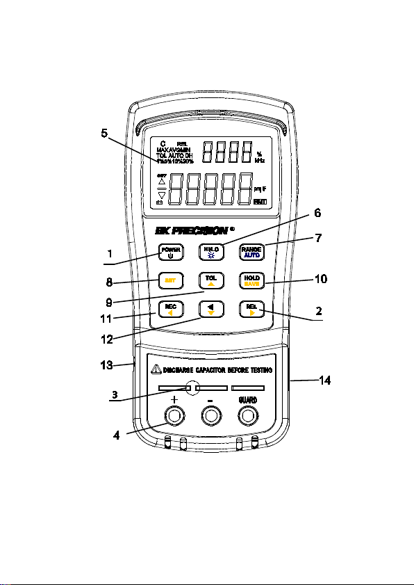
FRONT PANEL OVERVIEW
Figure 1 - Front Panel Display (model 830C shown)
14

Front Panel Display Descriptions
1. Power ON/OFF Button
2. Relative mode / right arrow selection button
3. Input sleeve terminals for positive (+),
negative (-), and guard (see “Guard Terminal”
in “SUPPLEMENTAL INFORMATION” section
for details)
4. Input sockets (banana jack inputs)
5. LCD Display
6. Set HI/LO limit / Back light button
7. Manual and Auto range button
8. Set button for entering HI/LO limit set function
menu
9. Tolerance mode / up arrow selection button
10. Data Hold / Save HI/LO limit settings button
11. Record mode selection button
12. Compare mode button
13. Standard mini USB port (for remote
controllability)
14. 12V DC adapter input (use with an ext erna l
power adapter (rated 12VDC, 150mA, 4mm
power plug))
Note: Use with included power adapter only.
Use with improper power adapters may
damage instrument.
15

WARNING: Before connecting an external
power adapter, please check the battery
compartment in the rear side of the unit. If
a battery is installed, be sure that the
polarity matches the (+) and (-) labels as
indicated inside the battery compartment.
If it is not installed correctly, please
remove the battery and install it with
correct matching polarity as indicated in
the compartment. See “Installing Battery
section for details. DO NOT, at any time,
connect an external power adapter when a
battery is installed incorrectly. Doing so
will damage the instrument and void its
warranty.
Front Panel Buttons
All front panel buttons have specific colored labels on
them. They are all marked in white, blue, or yellow
color. Each color has a specific representation, as
described below:
”
White – With the exception of the
button, all white colored labels
represent the primary function of that
16
button; meaning that function will be
set or configured upon pressing it. To
escape out of the functions, hold and
press the corresponding button for
two seconds.
Blue – Some of the buttons have a blue label
underneath a white label. This means
the function indicated by the blue
label will be set if that button is
pressed and held for 2 seconds.
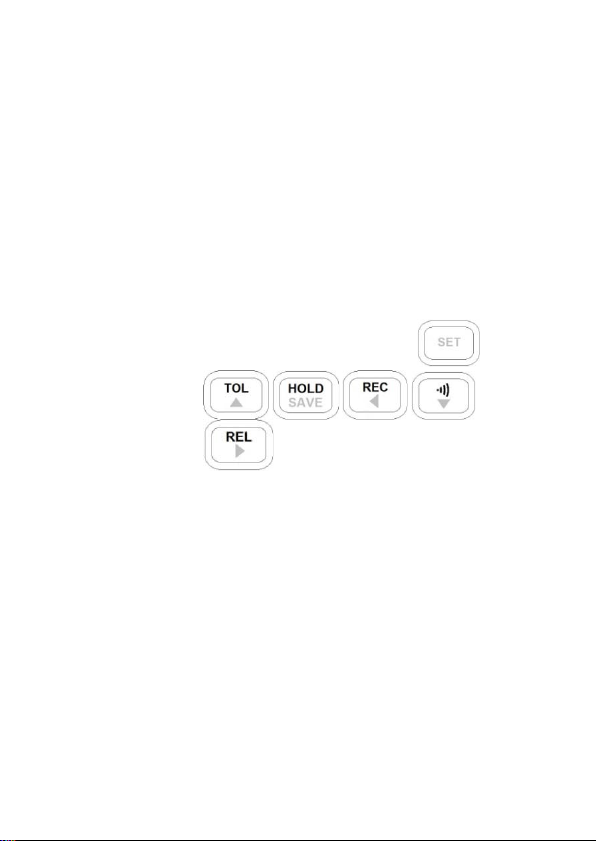
Yellow – There are total of 6 buttons with
yellow labels. They are
. These functions are
exclusively for use when entering the
SET menu for configuring setup menu
items as well as compare function.
See “Setup Menu” and “Compare
Mode” sections respectively for
details.
17
LCD DISPLAY OVERVIEW
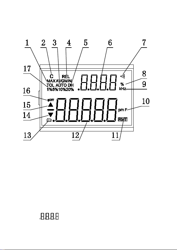
Figure 2 - LCD Indicator Display
LCD Display Descriptions
1. MAX AVG MIN – Static Recording mode,
indicates present reading
2. C – Reading indicator
3. AUTO – Auto range
4. REL – Relative mode indicator
5. DH – Data Hold
6. – Secondary display
18
Test Equipment Depot - 800.517.8431 -
99 Washington Street Melrose, MA 02176
- FAX 781.665.0780 - TestEquipmentDepot.com
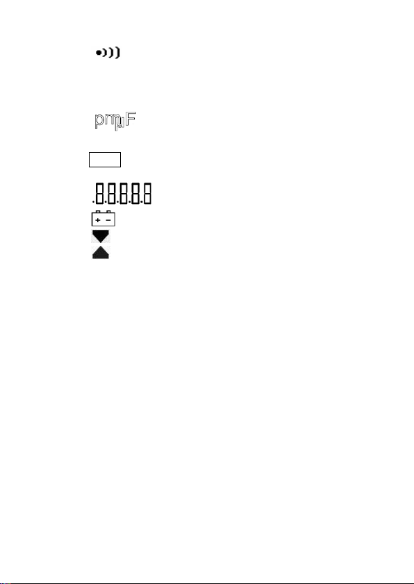
7. – Beep tone indicator for tolerance and
compare mode
8. % - Tolerance percentage indicator
9. kHz – Frequency units indicator
10. – Capacitance units (Farad) indicator
(Actual display will show pF, mF, or µF)
11. RMT – Remote mode indicator
12. – Primary display
13. – Low battery indicator
14. – Reading out of the LO limit
15. – Reading out of the HI limit
16. @OFF – Enable Auto Power off indicator
17. TOL 1%5%10%20% - Tolerance mode
percentage for sorting capacitance
19
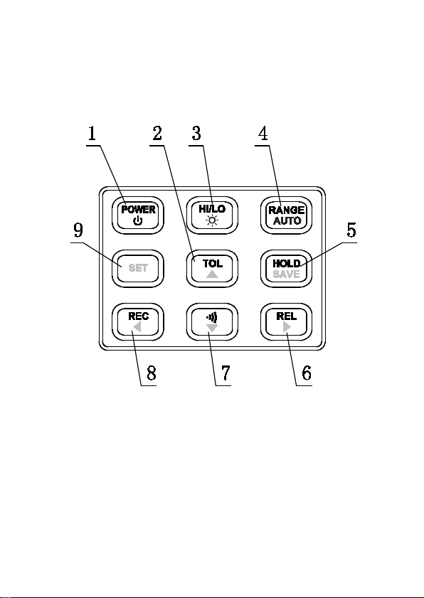
PUSH BUTTONS OVERVIEW
Figure 3 - Front Panel Buttons
1. Power ON or OFF
2. Tolerance Mode
3. HI/LO Limits for compare mode and to enable
backlight
4. Auto or Manual range
20

5. Data hold and save setting for compare mode
6. Relative mode and right arrow key
7. Compare mode and down arrow key
8. Record mode and left arrow key
9. Set HI/LO limits for compare mode
21

POWERING INSTRUMENT
Before operating the instrument, make sure to
connect it to a power source, which could be either a
battery or an external AC adapter.
Installing Battery
The 830C and 890C capacitance meters can be
powered by a battery, thus making it portable.
The meters use a standard 9V size battery (or
NEDA 1604, JIS006P, IEC6F22 carbon-zinc or
alkaline battery).
To install the battery:
1. Place the meter upside down. Open up the
back-flip stand, and locate the screw that
tightens the battery compartment cover as
indicated in Figure 4. Use a screwdriver to
unscrew and remove the cover.
22
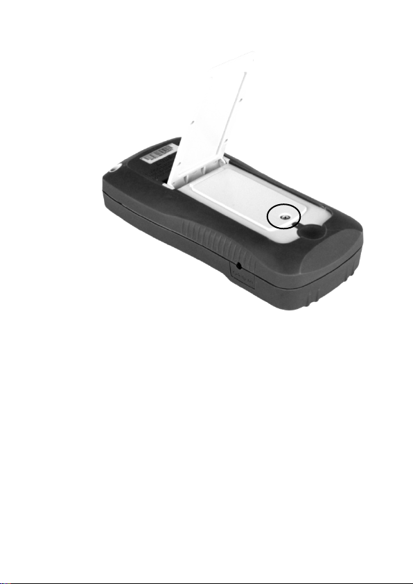
Figure 4 - Back Cover
2. Insert 9V battery into compartment. Note the
positive (+) and negative (-) terminals as
indicated inside the battery compartment (See
Figure 5). Be sure to insert the batter y with
matching polarity.
23
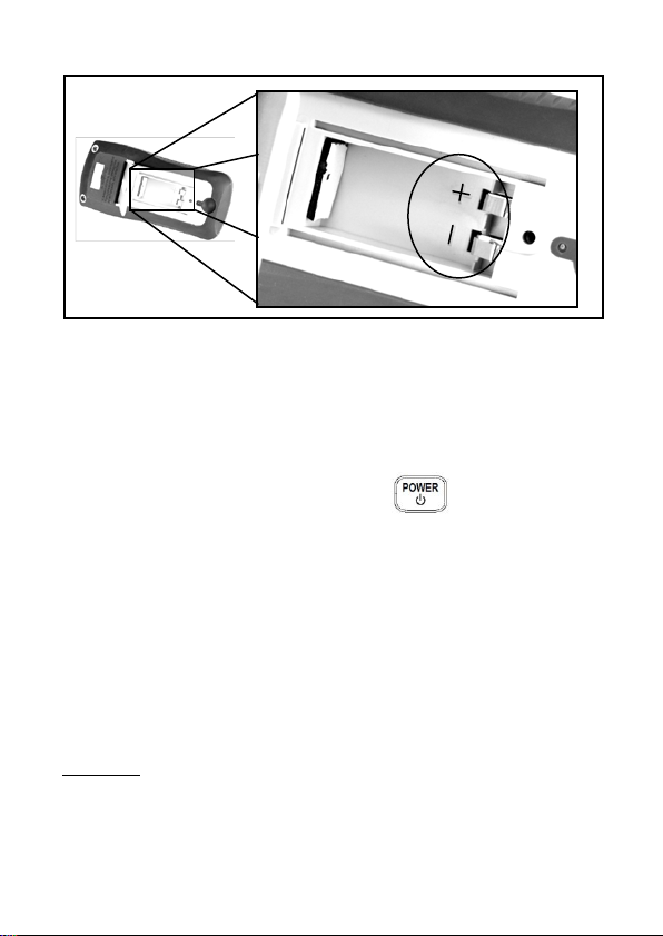
Figure 5 - Battery Compartment
3. Place the battery compartment cover piece by
sliding it into the top slid first. Place screw at
the bottom of the cover piece and tighten
down with a screw driver.
4. Push and hold down the button for 2
seconds to turn on the instrument.
Connecting External Power Source
The 830C and 890C can also be powered using an
external AC adapter. The model 830C comes with
this adapter included in the pac kage, while it is
optional
available. One with 110 V AC line voltage input, and
one with 220 V AC li ne volt age input. Be sure to use
for model 890C. There are two types
24

one that has the correct AC line voltage input for use
in your country.
For external power, use AC adapter rated for
output 12VDC, 150mA, with a standard 4mm
connector only.
WARNING: Use of incorrect adapters may damage
the instrument. Please use B&K Precision’s adapter
only. Be sure to use one with the correct AC line input
voltage.
To connect the adapter, do the following:
1. If a battery is installed, please check the
battery compartment again that the polarity of
the battery matches the polarity as indicated
by the labels inside the compartment. If it is
not, please remove and insert the battery with
matching polarity. If a battery is not installed,
continue to the next step.
WARNING: DO NOT, at any time, connect
an external power adapter when a battery
is installed incorrectly (reverse polarity or
non-matching polarity to indicator of
battery compartment). Doing so will
damage the instrument and void its
warranty.
25

12VDC Input
Figure 6 - Connecting AC Adapter to Meter
2. Connect the AC adapter connector into the
right side panel of the instrument. See Figure
6 below.
3. Now, connect the AC Adapter socket into an
electrical outlet.
4. Push and hold down the button for 2
seconds to turn on the instrument.
AC Adapter
Note: The meter can be operated with a battery
installed while an AC adapter is plugged in at the
same time (As long as the battery is inserted properly
with correct polarity). In this event, the meter will
automatically switch to consume power from the AC
adapter instead of the battery to preserve battery life.
26
Low Bat tery Indication
The capacitance meter has a low battery indicator to
notify the user when to replace the battery. When the
display starts flashing the indicator, the battery
voltage is below normal working voltage. In this case,
accuracy of the meter will also decrease. It is
recommended that the battery be replaced as soon as
possible before continuing operation. See “Installing
Battery” for instructions.
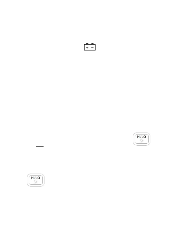
Backlit Display
The capacitance meter has a backlit display that
allows you to see the LCD display in dark conditions.
To turn on the back light, press and hold the
button for 2 seconds. Back light will turn on and
brighten the LCD display.
To turn off the back light at any time, press and hold
the button for 2 seconds again. Back light will
turn off and return to normal display.
27
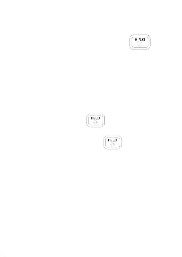
When Using Battery Power
When the meter is powered using 9V battery, the back
light display will turn on upon holding the
button for 2 seconds. It will stay at maximum
brightness for 15 seconds if backlight settings are set
to default value.
When Using External Power
When the meter is powered using an external AC
adapter, the back light display will turn on upon
pressing and holding the button for 2 seconds.
It will stay at maximum brightness continuously until
the user presses and holds the button for 2
seconds again.
Note: If a battery is installed while using an AC
adapter simultaneously, unplugging the AC adapter
will automatically start the back light timer configured
under “SETUP OPTIONS” and back light will turn off
once the time is up.
Test Equipment Depot - 800.517.8431 -
28
99 Washington Street Melrose, MA 02176
- FAX 781.665.0780 - TestEquipmentDepot.com

PUSHBUTTON
DESCRIPTION
Reset the high and the low limits to
REL
To see firmware version
Setup menu for configuration
settings of the meter.
POWER ON OPTIONS
To select power on options, press and hold the
pushbutton as indicated in the table below while
turning on the meter. For example, press and hold
and press to enter setup menu.
SET
factory default values.
Reset HI/LO Limits
To reset the high and low limit values to factory
default values, press and hold the and press
button. Keep holding the button for
five or more seconds or until you hear two audible
beeps. Now, release and all HI and LO limit values
are reset back to factory default values.
29

Note: If you released the button before
hearing the two beeps, the display will not show any
digits on the primary display for a few more seconds.
Please wait until it displays digits before oper at io n.
View Firmware Version
To check the firmware version of the meter, press and
hold and press the button. Keep
holding the button for two seconds and
release. The screen will now show the version. At
this point, the power button is disabled
resume normal operation, press any other button
except the power button and it will go into normal
display.
. In order to
Setup Menu
To enter the setup menu of the meter, press and hold
the and press the button. Keep
30

item
Setting
19200
PArt
NONE
Parity: odd, even, none
Data
8-b
Data bits: 8 bits or 7 bits (Stop bit
holding until “bAUd” is displayed on the
primary display. For details on configuring settings,
please see SETUP OPTIONS section. To exit setup
menu, press and hold for 2 seconds and the
meter will return to normal display.
SETUP OPTIONS
There are various system parameters that the meter
can be configured for when entering the setup menu
(see “Setup Menu” section for instructions on how to
access the menu). The below table lists these
parameters, as well as their factory default settings
and selectable parameters.
Table 1 - Setup Menu System Settings and Default
Menu
bAUd 9600
Factory
Selectable Parameters
Baud rate: 2400, 4800, 9600,
31

is always 1 bit)
ECHO
OFF
Echo: “ON” or “OFF”
Prnt
OFF
Print: “ON” or “OFF”
beep
ON
Beep: “ON” or “OFF”
buttons “ON”: disable pushbuttons
1~99 minutes, “OFF” means to
disable auto power off.
automatically.
Bright level of backlit at OFF state:
OFF~03
OFF~03
Reset all above items to factory
default settings
LbUt OFF
AOFF 15
bLIt 15
bOFF 01
bON 03
dEFA rSt
NOTE: After changing any or all setting options
within the setup menu, press and hold
button for two seconds or until a b eep is sound to
save settings. The meter will NOT
changed settings if this is not done upon exiting
the setup menu.
Lock buttons , “OFF”: enable push
1~99 seconds, “OFF” means to
disable turning off backlit
Bright level of backlit at ON state:
store the
32

Baud Rate (bAUd)
The baud rate is used for communication with a PC
over the USB interface. For PC communication, the
baudrate MUST match the settings on the PC side.
Selectable rates are (in units of bps):
2400, 4800, 9600, 19200
Note: The secondary display of the meter will show
the rates with units as “kHz”, but it’s actually a
reference for multiple of 1000 or “x 10
9.6 kHz means 9.6 x 10
3
= 9600.
3
”. For example,
33

Figure 7 - Steps to Change Baud Rates
34

Parity (PArt)
The parity setting is used for communication with the
PC over USB interface. For PC communication, parity
MUST match the settings on the PC side.
Selectable parameters are:
None, Even, Odd
Figure 8 - Steps to Change Parity
35

Data Bits (Data)
The data bits setting is used for communication with a
PC over USB interface. For PC communication, data
bits MUST match settings on the PC side.
Selectable parameters are (in units of bits):
8, 7
Figure 9 - Steps to Change Data Bits
36

Echo (ECHO)
The echo function will set the meter to “echo” or return
all characters that are received. For example, if
“*IDN?” is sent to the meter, it will return “*IDN?” as
well as the queried information.
Selectable parameters :
OFF, ON
Figure 10 - Steps to toggle Echo Settings
37

Print Only (Prnt)
Under remote operation, when the meter is set with
print only mode to “ON”, it will print out measured data
when the measurement cycle is complete and
automatically send the newest data to the PC
continuously. In this mode, any commands sent from
the PC will not be accepted. The remote indicator on
the meter display will flash when this mode is enabled.
Selectable parameters :
OFF, ON
Test Equipment Depot - 800.517.8431 -
38
99 Washington Street Melrose, MA 02176
- FAX 781.665.0780 - TestEquipmentDepot.com

Figure 11 - Steps to Change Print-Only Setting
Key Beeper (bEEP)
The key press beep sound can be enabled or
disabled.
Selectable parameters :
ON, OFF
39

Figure 12 - Steps to Toggle Key Keep
Lock Buttons (LbUt)
The front push buttons can be locked by changing the
settings of this option. When “ON”, buttons will be
locked and cannot be pressed upon turning on the
meter. All buttons are disabled at this point except the
button, which can be used to turn off the
meter. The power-on option can still be operated
even if buttons are locked. This will provide users
40

with a means to disable or unlock the buttons when
necessary.
Selectable parameters :
OFF, ON
Figure 13 - Steps to Change Lock Buttons Settings
Auto Power Off (AOFF)
This option will allow a timer to be set for auto power
off. When enabled, the display will have “@OFF”
41

indicator. When disabled, the meter will run
indefinitely.
Note: The timer will not be in effect if any of the
below happens:
1. Push buttons are used.
2. Static recording is set.
3. Auto power off is disabled or “OFF”.
If any of the above conditions do not apply, the timer
will start counting based on the timer setting
configured.
Selectable parameters :
OFF, 1 – 99 minutes
42
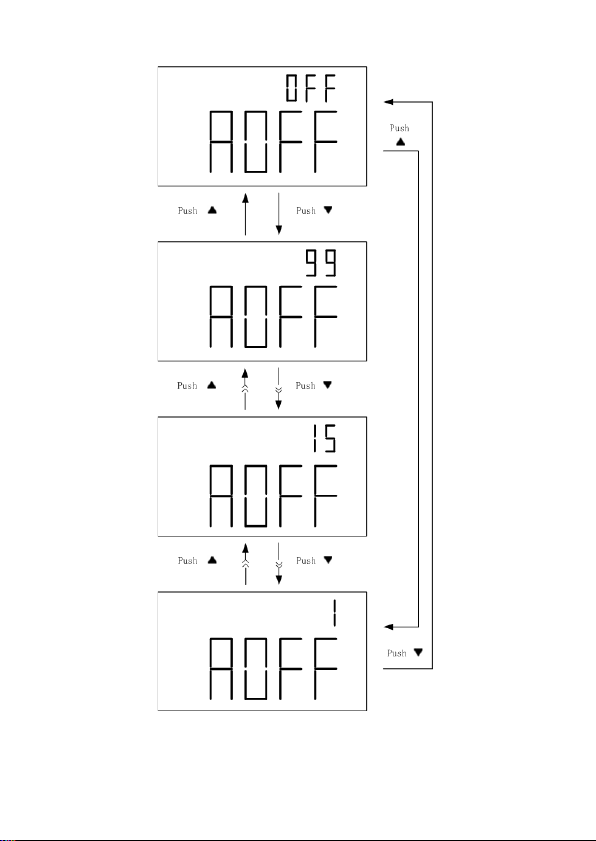
Figure 14 - Steps to Change Auto Power Off Settings
43

Backlit Display Time (bLIt)
Back light of the meters can be turned off
automatically with a timer. Once set, back light will
remain on for the period of the timer setting upon
enabling the back light by pressing and holding
for two seconds. If it is set to “OFF”, the
back light will remain ON indefinitely.
Selectable parameters :
OFF, 1 – 99 seconds
Note: To conserve and extend battery life, select a
shorter timer setting.
Bright Level Off State (bOFF)
This option allows users to set the brightness level for
the “off state” of the back light. The “off state” refers
to the state after backlight is enabled and backlight
timer (bLit) ends. For example, this option is used
when users want backlight to be enabled for a period
of time (set by bLit) and then dim the brightness
indefinitely afterwards. When set to “OFF”, back light
will be off in the off state. If a level is set, the backlight
will be on with the selected brightness level after
backlight is enabled and backlight timer ends.
44

Selectable parameters ,
OFF, 01, 02, 03
Note: “03” is the brightest and “01” is the dimmest.
45

Figure 15 - Steps to Change Back light Off State
46

Brightness Level On State (bON)
This option allows user to set the brightness level for
the on state of the back light. When it is set to “OFF”,
back light will be in the lowest brightness level in the
on state. If a level is set, the backlight will be much
brighter when backlight is enabled by pressin g the
button.
Selectable parameters ,
OFF, 01, 02, 03
Note: “03” is the brightest and “01” is the dimmest
level. However, when se t, “ OFF” state will still be the
lowest brightness level.
47

Figure 16 - Steps to Change Back light ON State
48
Test Equipment Depot - 800.517.8431 -
99 Washington Street Melrose, MA 02176
- FAX 781.665.0780 - TestEquipmentDepot.com

Reset to Default (dEFA)
This option will reset all setup option parameters back
to default values as listed in Table 1 - Setup Me nu
System Settings and Default. To reset, simply press
and hold the button for two seconds. The
meter will then be resetting all parameters
immediately. All push buttons will not respond
immediately, so wait for approxim ately 5 seconds unt il
the display changes and returns to “bAUd” option.
Once this is displayed, users can verify that all
settings under setup menu are set to factory default.
49

Figure 17 - Reset to Factory Default
50

OPERATION INSTRUCTIONS
Data Hold/Trigger Hold
The data hold/trigger hold function allows the user to freeze
the display when pressed, holding the measured value until
data hold is turned off.
Turn On Data Hold
To use data hold, press the button once. The “DH”
indicator will display on the screen when data hold is active.
Trigger Hold
Users can send a trigger hold once data hold has
been turned on. While “DH” indicator is displayed, all
subsequent key press of the
trigger to acquire a reading and hold immediately.
button will send a
Turn Off Data Hold
To disable the data hold, press and hold button for
two seconds. The “DH” indicator will disappear on the
screen, and meter will turn to normal operation mode.
51

Figure 18 - Data/Trigger Hold Operation
52

Static Recording
This mode is used for recording maximum, minimum, and
average capacitance values. It captures only s table values
and updates to memory. Values that result in displaying
“OL” or that are below 10 counts are not recorded. This
mode is useful for determining the range of values a
component falls into.
Enable Static Recording
Press the button to enter the static recording mode.
The display should indicate “MAX AVG MIN”
simultaneously. This indi cate s the meter is in static
recording mode and recording is performed immediately.
Note: In static recording mode, the auto power off function
will be disabled and the “@OFF” indicator will be turned off
automatically. It will be re-enabled with its previous settings
once meter exits static recording mode.
Using Static Recording
There are four different modes that can be selected in
static recording. These modes can be changed with
each button press. With each press of the
button, the modes will cycle through as
followed: :
53

Recording Mode Maximum Mode Minimum
Mode Average Mode
Recording Mode
This is the default mode when first enabling static
recording. In this mode, the “MAX AVG MIN”
indicator will be displayed. At this point, the meter will
start recording measured values applied to the input
sockets or terminals. During the recording process,
maximum, minimum, and average values will be
stored. A beep will sound once a recording has been
stored.
Note: Subsequent beep tones may occur in this mode if
there are new values that are recorded. For example, if a
new maximum is detected, it will beep once again to indicate
that the new value has been stored. Any previously stored
values will be overwritten with the new recorded values.
Maximum Mode
In this mode, the “MAX” indicator will be shown on display.
This indicates that the value in the primary display
represents the recorded maximum value.
54

Minimum Mode
In this mode, the “MIN” indicator will be displayed. This
indicates that the value in the primary display represents the
recorded minimum value.
Average Mode
In this mode, the “AVG” indicator will be displayed. This
indicates that the value in the primary display represents the
recorded average value. This average value is obtained by
taking the maximum and minimum recorded values and
taking the average of the two values.
Disable Static Recording
To exit this mode, press and hold the button for
two seconds. The “MAX AVG M IN”, “MAX”, “MIN”, or
“AVG” indicator will disappear on screen, and auto power off
will be re-enabled again if it was enabled prior to entering
static r ecording mode. “@OFF” indicator will come back on
when enabled.
55

Figure 19 - Steps to Use Static Recording
56

Relative Mode
Relative mode is used when the user wants to “zero”
the meter based on a reference value or wants to
obtain a reading that is relative to a reference value.
For example, if test leads are used in the
measurement, the user may want to set a reference
with the test leads inserted into the input terminals so
that any measurements taken will not take into
account the test leads.
Setup Relative Mode
To setup the relative mode, simply press the
button once. The value that is on the display will
immediately be stored as the “reference” value. This
reference value will be used for all measurements so
as long as the meter is in relative mode, which is
indicated by the “REL” indicator on the display.
A common use of relative mode is to “zero” out the
meter. With nothing connected to the input sockets
and terminals, simply press the button once
and the meter will “zero” out, meaning all display
readings will be set to 0.
To make measurements within a specific test setup or
with test leads, it is recommended that the user first
57

have test leads or wires connected to the meter in the
fashion that they desire. Then, press the
button once to “zero” out the meter as reference. This
way, any measurements taken would not be affected
by the test leads or setup.
Note: Relative mode can be set in both auto and
manual range, but cannot be set when “OL”, or
overload is displayed on the meter.
Disable Relative mode
To disable relative mode, simply press and hold the
button for two seconds. The “REL” indicator
will disappear, which indicates the relative mode is
disabled.
Test Equipment Depot - 800.517.8431 -
58
99 Washington Street Melrose, MA 02176
- FAX 781.665.0780 - TestEquipmentDepot.com

Figure 20 - Steps to Use Relative Mode
59

Tolerance
The tolerance mode feature is specifically used for
component sorting purposes. Users who need to test
and sort through a large number of components will
find this function quite helpful.
Tolerance Range
The tolerance function is configured primarily by
percentage range, meaning a percentage is used to
define whether a measured value is within tolerance
or out of tolerance.
Selectable tolerance range is: 1%, 5%, 10%, and
20%.
Setup Tolerance
1. Insert the component to be used as the
“standard” reference value. In other words ,
insert a known “good” component that will be
used for testing against all other components.
(See Figure 21 for illustration)
Note: The tolerance mode cannot be
activated unless the meter senses that a
60

capacitance is connected to either the input
sockets or terminals.
WARNING: Be sure that the capacitor is fully
discharged BEFORE
sockets or terminals. For large capacitors, it
may take longer periods of time for a full
discharge. Inserting a charged or partially
charged capacitor into the meter’s input
sockets or terminals may produce an electric
hazard and may also damage the instrument,
thus rendering it unusable.
inserting it into the input
Figure 21 - Inserting Capacitance to Inputs
61

2. Once the desired measured reading is
displayed, press the button once to
store the reading as the “standard” value or
test reference value. At this point, the “TOL”
will be displayed on the screen, indicating that
the tolerance mode is activated.
3. To select the tolerance range, press the
button once more. For each button
press, the meter will cycle through the
tolerance range percentage in this order: 1%,
5%, 10%, 20%. These percentage ranges will
also be indicated on the LCD display by the
indicators “1%”, “5%”, “10%”, or “20%”
respectively. The component to be tested will
be verified within the selected tolerance % of
the “standard” value or test reference value
(as configured from step 2).
4. Within a few seconds, an audible tone will be
heard.
One single “beep” or tone means the
component is within tolerance
Three “beeps” or tones means the component
is out of tolerance
.
.
62

Note: Under the following instances, the tolerance
mode cannot be set:
1. After setting recording mode
2. After setting HI/LO limit for compare mode
3. The display shows “OL” for overload.
Disable Tolerance Mode
To disable or exit out of tolerance mode, simply press
and hold down the button for two seconds.
The “TOL” and/or the percentage indicators “1%”,
“5%”, “10%”, or “20%” will disappear on the LCD
display.
63

Figure 22 - Steps to Setup Tolerance Mode
64

Set
1
100
90 2 120
108 3 150
135 4 180
162 5 220
198 6 270
243 7 330
297 8 390
351 9 470
423
10
560
504
11
680
612
12
820
738
13
1000
900
14
1200
1080
15
1500
1350
16
1800
1620
Compare Mode
This function allows you to sort capacitors and to
configure 25 sets of limit ranges. The meter comes
with preconfigured stored values for high and low
limits. See table below:
Table 2 - High/Low Limit Default
Comparison
High limit Low Limit
65

17
2200
1980
18
2700
2430
19
3300
2970
20
3900
3510
21
4700
4230
22
5600
5040
23
6800
6120
24
8200
7380
25
10000
9000
Setting Compare Mode
The following procedure demonstrates how to set
compare mode.
1. Press button to enter HI/LO audible
alert compare mode. The range will be locked
in this mode. The meter will display the “
” indicator on the upper right. The
secondary display will indicate “C01” to “C25”
depending on which set was last saved during
previous operation. The last two digits
indicate the current comparison set of HI/LO
limits. The primary display indicates the
present measurement.
66

2. Press the button to cycle through the
sets from “C01” to “C25”.
3. Press the button to see the HI and LO
values used for the comparison. As an
example, the display will cycle through set 5 in
this order: “C05”, “L05”, “H05”. The values
will briefly display for one second and will
return to normal compare display. In the
example, it would just return to display “C05”
on the secondary display.
18. If the reading is outside of the HI or LO limits,
three audio beeps will sound, and the
secondary display will show “nGO” for “no
go”. There will be an up or down arrow
indicator on the left next to the primary
display. arrow indicates the value is too
high and fails the test. arrow indicates the
value is too low and fails the test. If the
reading is within the HI or LO limits, one audio
beep will sound and the secondary displa y will
show “GO”. After three seconds, the meter
will return to ready state again.
67

Exit Compare Mode
To exit compare mode, simply press and hold
for two seconds. The “ ” indicator will disappear
from the upper right corner of the display, indicating
that meter is no longer in compare mode.
Test Equipment Depot - 800.517.8431 -
68
99 Washington Street Melrose, MA 02176
- FAX 781.665.0780 - TestEquipmentDepot.com

Figure 23 - Steps to Setup Compare Mode
69

Figure 24 - Steps to Sort by Compare Mode
70

Setting HI and LO Limits
The yellow keys from the front key buttons are used
for setting HI and LO limits for compare testing. The
button enters the HI/LO limit setup menu.
The arrow buttons , , , and
are used to adjust the HI/LO sets and HI/LO
limit values. The button is used to save the
adjusted limit values.
Follow the below procedure to configure HI/LO limits.
1. Press and hold for two seconds to
enter HI/LO limit setting mode.
2. The secondary display will flash “L01” and the
primary display will indicate the limit value.
Default is displayed as “0090”. This indicates
the limit value for the first set for the “LO” limit.
Use the or button to select the
digits of the limit value, going left or right
respectively. The digit that is blinking rapidly
indicates the current selection.
71

3. Once the digit you want to adjust is blinking,
use the or to increase or
decrease the value of the blinking digit.
4. Once the desired limit value is set, press and
hold button for two seconds or until
all the digits on the primary display stops
blinking.
5. To set the “HI” limit value for the first set,
press the button once and the
secondary display will show “H01” blinking
slowly.
6. To adjust the next set of limit values, simply
press the button once. The
secondary display will now show either “H02”
or “L02” depending on whether the last set
limit was for HI or LO.
7. Repeat steps 2-5 for this second set of limits.
The meter can store up to 25 different limit
sets. Repeating the above steps will cycle
through “01”, “02”, “03”, … , “25”. After the
th
set, it will go back to the 1st set again.
25
72

Exit HI/LO Limit Menu
Once all limit values are configured for all the sets to
be used, hold and press the button for two
seconds to exit.
73

Figure 25 - Steps to Set HI/LO Limits
74

REMOTE COMMUNICATION
The meter has the capability to communicate with a
PC over the mini USB interface. Upon installation of a
USB driver, the PC can control the instrument over
virtual COM. The mini USB communication interface
of the meter is fully duplex and has a 64-byte input
and output buffer, making it reliable and efficient for
data transmission.
Connecting Instrument to PC
Follow the below procedures for connection setup.
1. Download the USB drivers
2. With the included mini USB cable, connect the
mini USB end to the capacitance meter and
the other end to an available USB port on the
PC.
3. When Windows recognizes the USB
connection, do not follow the default Windows
driver installation wizard. Simply run the
setup file from the downloaded USB drivers
and follow the prompt to install drivers.
4. When completed, the computer will recognize
the instrument as a USB (virtual COM) device,
meaning it will be detected as a serial COM
75

port. Windows will automaticall y assign a
COM port to the instrument. Please verify
which COM port Windows has assigned by
going into “Device Manager”.
USB (Virtual COM) Configuration
The USB will be recognized as a virtual COM on the
PC, thus serial port settings must be configured
properly for remote communication to be successful.
Below are the default settings used by the 830C and
890C meters. They can be changed within the setup
menu. See SETUP OPTIONS section for details.
• Baudrate: 9600
• Dat a bits: 8
• Parity: None
• Stop bits: 1
• Flow Control: None
Remote Mode
Upon connecting to the instrument, sending any
commands listed in the “Command Protocols
will automatically set the meter into remote mode. In
remote mode, the LCD display will show the
indicator.
76
” section
RMT

Command Protocols
Overview of Command Type and Format
All commands are entered in either the upper case or
the lower case. There are two types of the meter
programming commands: IEEE 488 common
commands and Standard Commands for
Programmable Instruments (SCPI). Some commands
are device-specific to the meter. They are not included
in the version 1999.0 of the SCPI standard. However,
these commands are designed with the SCPI format
in mind and they follow the syntax rules of the
standard.
Common Command Format
The IEEE 488 standard defines the common
commands as commands that perform functions like
reset and system query. Common commands usually
come with the asterisk “*” character, and may include
parameters. Some examples of Common command
like: *IDN?, GTL, LLO.
SCPI Command Format and Query Format
The SCPI commands control instrument functions. A
subsystem command has a hierarchical structure that
usually consists of a top-level (or root) keyword, one
or more lower level keywords, and parameters. The
77

following example shows a command and its
associated query:
CONFigure:CAPacitanc e 1 0u
Set the primary display to the capacitance
measurement, and select the 10 uF range.
CONFigure?
Return the function of the primary display
measurement.
CONFigure is a root level keyword with the second
level keyword, CAPacitance, and 10u is the command
parameter. The query command ends with a question
mark “?”.
Note: SCPI stems from IEEE488.1 and IEEE 488.2.
Although the IEEE 488.2 standard addressed some
instrument measurements , it princ ip al ly dealt wit h
common commands and syntax or data formats.
Please refer to the IEEE488.2 and SCPI reference
manual for more information.
Termination Character
A terminator is a character sent by a host, which
identifies the end of a command string. A valid
terminator consists of two-byte data:
<CR> (Carriage Return, ASC(&H0D)) or <LF> (Line
Feed, ASC(&H0A)) or <C R >< L F >
Test Equipment Depot - 800.517.8431 -
78
99 Washington Street Melrose, MA 02176
- FAX 781.665.0780 - TestEquipmentDepot.com

Data Type
Explanation
Example
<NR1>
An integer
+800,-200,100,-50
This numeric
point
<NR3>
This representation
+2.345678E+04
Responding Message
Returned result
After the meter executes a query command, the return
of the result will be in the following format:
<Result> + <CR> <LF>
For example, in auto fetching mode, the meter will
send the measured data automatically when the
measurement cycle is completed. The format of the
printed data will be shown as the following:
<Result > + <CR> <LF>
Data Types
Returned message is an ASCII string from the meter
responding to a query. A query is a command
accompanied a “?” mark. Table 3 below explains the
different data types.
Table 3 - Data Type of Responded Message s
<NR2>
representation has
an explicit radix
79
+1.56,-0.001,10.5

exponent
query command
short literal form
Text Symbol
Meaning
[ ]
Option; can be omitted
|
Exclusive OR
has an explicit
-1.345678E-01
radix point and an
A parameter for
Boolean setting.
<Boolean>
Always return “0”
ON or OFF
or “1” for Boolean
A string is used as
<Literal>
command
parameters with
HOLD
SCPI Commands
This section described all the SCPI commands
supported by the meter. The meter can accept both
upper case and lower case commands.
Table 4 - SCPI Symbol Conventions
80

< >
Defined element
( )
Comment
?
Question mark
keywords
version>, <serial number>
Description: Set to 2-wire capacitance
measurement.
:
*IDN?
Description: Queries the instrument ID.
Response: <instrument model>, <firmware
LLO
Local Lockout. This means that all front panel buttons
are disabled except for button.
GTL
Go to local.
Puts the meter into the local state,
clearing the remote state and front panel lockout.
CONFigure Subsystem
CONFigure:CAPacitance [<range>]
Separated two command
81

function and 100μF range.
Description: Query the function of the primary
CAP
07,+1.000000E-1
Parameter:
<range> : Measuring unit is Farad. Parameters
are 1000p, 10n, 100n, 1u, 10u, 100u, 1m, 10m
and 50m (will be 200m range for 830C). The
meter is set to auto range when the parameter is
omitted.
Example: CONF:CAP 100u ; Set to capacitance
CONFigure?
display.
Response: Return <”function range, resolution”>
format string, the examples are as
following:
+1.000000E-
Capacitance 100nF 0.01nF
82

Description: Enable or disable the function of
combinations are void.
CALCulate Subsystem:
CALCulate:FUNCtion NULL
TOLerance
LIMit
AVERage
NONE
the calculation.
Parameter:
NULL – enable null (relative) function;
TOL – enable tolerance function;
LIM – enable limit function;
AVER – enable average (static recording)
function;
NONE – disable all calculation and select the
internal trigger source.
Example: CALC: FU NC A VER
Note: The trigger source is changed to
immediate when the AVERage
function is enabled.
User can combine TOL/NULL,
LIM/NULL, AVER/NULL or
NULL/AVER functions, but the other
83

function being enabled.
Description: Query the offset value of the null
Response: Return <NR3> format string.
CALCulate:FUNCtion?
Description: Query the function of the
calculation.
Response: Return <Literal> format string:
AVER, TOL, LIM, NULL or NONE.
For combined modes, string can be:
TOL,NULL; LIM,NULL; AVER,NULL
Example: Returning AVER, NULL means the
record function and the relative
CALCulate:NULL:OFFSet?
(relative) function.
Note: If relative function is disabled, querying the
offset of relative mode will return an error. Reenable in order to get a returned value. Use
CALCulate:NULL:STATe command shown below
to control the relative function.
84

Description: Enable or disable the null
Example: CALC:NULL:STAT OFF
Description: Query the value of the static
recorded value.
CALCulate:NULL:STATe <Boolean>
(relative) function of the calculation.
CALCulate:AVERage
:MAXimun?
:MINimun?
:AVERage?
:PRESent?
dynamic recording function.
Response: Return <NR3> format string.
Example:
CALC:AVER:MAX? ; Query the maximum
recorded value.
CALC:AVER:MIN? ; Query the minimum
recorded value.
CALC:AVER:AVER? ; Query the average
recorded value.
CALC:AVER:PRES? ; Query the present
85

Description: Enable or disable the static
Example: CALC:AVER:STAT OFF
Description: Set the mode or the value of the
value of the 7th set.
Note: If static recording function is disabled, all
queries will return an error message on disp lay
until the function is re-enabled again. Use
CALCulate:AVERage:STATe command shown
below to control static recording function.
CALCulate:AVERage:STATe <Boolean>
recording function of the calculation.
CALCulate:LIMit
:MODE <mode>
:LOWer <mode>, <value>
:UPPer <mode>, <value>
Limit function.
Parameter:
<mode>: The value of mode is from 01 to 25.
<value>: The limit value is from 00000 to 11000.
Example:
CALC:LIM:MODE 01 ; Apply the settings of
the mode 1.
CALC:LIM:UPP 07,01000 ; Set the upper limit
86

Description: Query the mode or the value of
of the mode 7.
CALCulate:LIMit
:MODE?
:LOWer? <mode>
:UPPer? <mode>
the Limit function.
Parameter: <mode>: The value of mode is
from 01 to 25.
Response: Return <NR1> format string.
Example:
CALC:LIM:MODE? ; Query the mode of the
Limit function.
CALC:LIM:UPP? 07 ; Query the upper value
Note: CALCulate:LIMit:MODE? Query will
respond with an error if meter is not in limit
function and if the state of limit function is
disabled. To set meter to limit function, use the
CALCulate:FUNCtion command.
87

Description: Enable or disable the Limit
Example: CALC:LIM:STAT OFF
tolerance range.
Response: Return <NR3> format string.
CALCulate:LIMit:STATe <Boolean>
function of the calculation.
CALCulate:TOLerance:RANGe <1 | 5 | 10 | 20>
Description: Set the tolerance range of the
Tolerance function.
Example: CALC:TOL:RANG 5 ; Set 5%
Note: Tolerance range can only be set when
tolerance function mode is set. When this
function is not set as the current mode,
CALCulate:TOLerance:RANGe command will
return an error on display.
CALCulate:TOLerance:BASE?
Description: Query the base value of the
tolerance function.
Test Equipment Depot - 800.517.8431 -
99 Washington Street Melrose, MA 02176
- FAX 781.665.0780 - TestEquipmentDepot.com
88

Description: Query the tolerance value of the
could be 3.535005e-03
Description: Enable or disable the tolerance
Example: CALC:TOL:STAT OFF
CALCulate:TOLerance:VALue?
tolerance function.
Response: Return <NR3> format string.
The returned value will not be in terms of %. For
example, if display shows 0.35%, return value
CALCulate:TOLerance:STATe <Boolean>
function of the calculation.
89

Description: Select a source of the trigger
disabled when entering into trigger mode.
Description: Query the type of the trigger
Return <Literal> format string: BUS, IMM.
TRIGger:Subsystem:
TRIGger:SOURce < BUS | IMMediate >
signal.
Parameter:
BUS – select a bus command source and enter
the trigger (hold) mode. In this mode, data hold
will be activated to hold each measured reading
after trigger is received from the bus.
IMM – select the internal trigger source.
Example: TRIG:SOUR BUS
Note: The AVERage function will be
TRIGger:SOURce?
source.
Response:
90

Description: Return the primary display value
Measuring Subsystem:
FETCh?
of device’s output buffer. Retrieves
the measurements taken by the
INITiate command and places them
into the device’s output buffer. The
query can return data any time that
the last reading is valid. The meter
generates an error -230 and no
result is returned when the meter is
in the trigger idle state and the data
is invalid.
Response: Return <NR3> format string.
Example: FETC? ; Return a primary
display value, e.g. +1.23450000 E +00 .
91

Description: Query the error message.
queue is one. Keep the last error.
Command
error
Parameter
error
Description: Query the version of the SCPI.
Response: Return 1999.0 string.
SYSTem Subsystem
SYSTem:ERRor?
Response: Return <Num ber, “Error String”>
format string. Table 4 is a list of
SCPI error message that might
occur during operation.
Note: The buffer size of the system error
Table 4 SCPI Error Message
Number Error String Number Error String
+0 No error -200
-100
SYSTem:VERSion?
92
-220
Execution
error

Description: Enable or disable the key beep.
Parameter: <Boolean>: ON; OFF.
Description: Enable or disable the backlit.
isn’t zero and the time comes up.
Description: Set a backlit time.
Note: Stored in non-volatile memory.
SYSTem:BEEP <B oo lea n >
SYSTem:BLIT <Boolean>
Parameter: <Boolean>: ON; OFF.
Note: The backlit is turned off
automatically when the backlit time
SYSTem:BLIT:TIME <second>
Parameter: <second>: 0 ~ 99. Set “0” to
disable auto off backlit function.
93

Description: Set an auto power off time.
Note: Stored in non-volatile memory.
affect the other calibrated data.
Item
Explanation
Average
function
0:off, 1:on
B
Null function
0:off, 1:on
C
Limit
0:off, A:mode 1 ~
SYSTem:AOFF:TIME <minute>
Parameter: <minute>: 0 ~ 99. Set “0” to
disable auto power off function.
SYSTem:DEFAult
Description: Setting default value to the nonvolatile memory includes SETUP value but don’t
STATus Subsystem:
STATus?
Description: Query the status of the meter.
Response: Returns a
<”ABCDEFGHIJKLMNOPQRSTU”> format string
(21 characters).
Each character represents the following:
A
94

function
Y:mode 25
Limit result
0:none, 1:Go, 2:Lo
nGo, 3:Hi nGo
range setting
Result
2:fail
Trigger
source
I:IMM, B:BUS
H
Unused
always 0
I
Unused
always 0
J
Beep
0:off, 1:on
Off
L
Back lit
0:off, 1:on
M
Meter mode
L:normal
N
Unused
always 0
O
Unused
always 0
P
Unused
always 0
Q
Unused
always 0
R
Rate
always 1
S
Battery
0:normal, 1:low
T
Unused
always 0
U
Auto range
0:off, 1:on
D
E
F
Tolerance
function
Tolerance
0:off, 1:1%, 2:5%,
3:10%, 4:20%, F:no
0:none, 1:pass,
G
Auto Power
K
0:off, 1:on
95

Command
Parameter
Explanation
CONFigure?
Query display
function
measurement
CALCulate
function.
:FUNCtion
<function>
Set a calculation
function.
:OFFSet?
Query the offset
function
:STATe
<Boolean>
Enable/disable the
:AVERage
:MAXimum?
Query the value of
:MINimum?
:AVERage?
:PRESent?
:STATe
<Boolean>
Enable/disable the
function
:LIMit
:UPPer
<mode>,<value>
:LOWer
<mode>,<value>
:UPPer?
<mode>
Summary of SCPI Commands
CONFigure
:CAPacitance [<range>]
:FUNCtion? Query the
:NULL
:MODE <mode> Set the value of the
:MODE? Query the value of
Configure the
meter perform
specified
calculation
value of the relative
relative function
the static recording
function
static recording
limit f u nction
the limit function
96

O
W
:STATe
<Boolean>
Enable/disable the
:TOLerance
:RANGe
<1 | 5 | 10 | 20>
Set the value of the
Tolerance function
:BASE?
Query the value of
the Tolerance base
:VALue?
Query the
tolerance value
:STATe
<Boolean>
Enable/disable the
tolerance function
:SOURce?
Query the trigger
:
L
e
r
?
TRIGger
limit function
97

:SOURce
<BUS | IMM>
Select a trigger
source
FETCh?
Returns a data any
reading is valid.
SYSTem
:AOFF:TIME
<minute>:0~99
Set an auto power
off time
:BLIT
<Boolean>
Enable or disable
the backlit
:TIME
<second>:0~99
Set a backlit time
:BEEP
<Boolean>
Enable or disable
:DEFAult
Set default value to
:ERRor?
Query error
:VERSion?
Query version of
STATus?
Query the status
source type
time that the last
the buzzer.
the non-volatile
memory
message
the SCPI
Error Codes
In certain situations, errors may occur, and an error
code will be displayed on the meter. Below defines
the error description based on the error code.
Err0r 1: Unknown command
Err0r 2: Parameter Error
Err0r 3: Syntax Error
Test Equipment Depot - 800.517.8431 -
98
99 Washington Street Melrose, MA 02176
- FAX 781.665.0780 - TestEquipmentDepot.com
 Loading...