

Page 1

INSTRUCTION MANUAL
v092711
Model 889B Bench LCR/ESR Meter with Component Tester
Page 2

Contents
CONTENTS ......................................................................................................................................... 1
1. INTRODUCTION .......................................................................................................................... 3
1.1 G
ENERAL
................................................................................................................................................................................ 3
1.2 I
MPEDANCE PARAMETERS
1.3 S
PECIFICATION
1.4 A
CCESSORIES
........................................................................................................................................................................ 5
........................................................................................................................................................................ 13
....................................................................................................................................................... 4
2. OPERATION ............................................................................................................................... 14
2.1 P
HYSICAL DESCRIPTION
2.2 M
AKING MEASUREMENT
2.2.1 Open and Short Calibrati on ................................................................................................................................................................................... 15
2.2.2 Relative Mode ......................................................................................................................................................................................................... 15
2.2.3 Range Hold ............................................................................................................................................................................................................. 15
2.2.4 DC Resistance Measurement ................................................................................................................................................................................. 16
2.2.5 AC Impedance Measurement ................................................................................................................................................................................. 16
2.2.6 Capacitance Measurement ..................................................................................................................................................................................... 16
2.2.7 Inductance Measurement ....................................................................................................................................................................................... 16
....................................................................................................................................................... 14
...................................................................................................................................................... 15
3. OPERATION MODE S ................................................................................................................ 17
3.1 R
EMOTE MODE COMMAND SYNTAX
3.2 R
EMOTE MODE COMMANDS
..................................................................................................................................... 20
................................................................................................................................................. 20
4. APPLICATION ............................................................................................................................ 26
4.1 T
EST LEADS CONNECTION
4.2 O
PEN/SHORT COMPENSATION
4.3 S
ELECTING THE SERIES OR PARALLEL MODE
.................................................................................................................................................... 26
............................................................................................................................................... 28
........................................................................................................................ 29
5. LIMITED THREE-YEAR WARRANTY ........................................................................................ 31
6. SAFETY PRECAUTION ............................................................................................................. 33
Page 3

Page 4

3
1. Introduction
1.1 General
The B&K Pr ecisio n Corp. 889B Synthesized In-Circ uit LCR/ESR M eter is a high a ccurac y test instrum ent used
for measuring inductors, capacitors and resistors with a basic accuracy of 0.1%. Also, with the built-in functions of
DC/AC Voltage/Current measurements and Diode/Audible Continuity checks, the 889B can not only help
engineers and students to under s tand the c h arac ter ist ic s of electronics components but also being an essential
tool on any service bench.
The 889B is defaulted to auto ranging. However, it can be set to auto or manual ranging by pressing the Range
Hold k ey. W hen LCR m easurement m ode is selected, one of the test frequenc ies, 100 Hz, 120 H z, 1 KHz, 10
KHz, 100 KHz or 200 KHz, may be selec ted on all a pplicabl e ranges. One of the test voltages, 50m Vrms, 0.25
Vrms, 1 Vrms or 1 VDC (DCR only), m ay also be selected on all applicable ranges . The dual display feat ure
permits simultaneous measur ements. When DC/AC voltage/current measurement m ode or the Diode/Audible
Continuity Check mode is selected, only the secondary display will be used to show the result of the
measurement.
The highly versatile 889B can perform virtually all t he functions of most bench t ype LCR bridges . W ith a basic
accuracy of 0.1%, this economical LCR meter may be adequately substituted for a more expensive LCR bridge in
many situations. Also, with the basic accuracy of 0.4% in voltage and current measurements, the 889B performs
the functions of a general purpose Digital Multi-Meter and can be used to replace the DMM on a service bench.
The 889B has applications in electronic engineering labs, production facilities, service shops, and schools. It can
be used to check ESR va lues of capacitors, sor t and/or select com ponents, measure unm arked and unknow n
components, and measure capacitance, inductance, or resistance of cables, switches, circuit board foils, etc.
The key features are as following:
1. Voltage Measurements:
AC : True RMS, up to 600Vrms @ 40 ~ 1K Hz
DC : up to 600V
Input Impedance : 1M-Ohm
2. Current Measurements:
AC : True RMS, up to 2Arms @ 40 ~ 1K Hz
DC : up to 2A
Current Shunt : 0.1 Ohm @ > 20mA; 10 Ohm @ ≤ 20mA
3. Diode/Audible Continuity Checks:
Open Circuit Voltage: 5Vdc
Short Circuit Current: 2.5mA
Beep On: ≤ 25 Ω
Beep Off: ≥ 50 Ω
4. LCR Measurements:
Test conditions
Frequency : 100Hz / 120Hz / 1KHz / 10KHz / 100KHz / 200KHz
Level : 1Vrms / 0.25Vrms / 50mVrms / 1VDC (DCR only)
Measurement Parameters : Z, Ls, Lp, Cs, Cp, DCR, ESR, D, Q and θ
Basic Accuracy : 0.1%
Dual Liquid Crystal Display
Auto Range or Range Hold
USB Interface Communication
Open/Short Calibrat io n
Primary Parameters Display:
Z : AC Impedance
DCR : DC Resistance
Ls : Serial Inductance
Lp : Parallel Inductance
Page 5

4
Cs : Serial Capacitance
( )
( )
( )
( )
( )
Ohm
Reactance
Resistance
Impedance
=Ω
=
=
=
−
==
+==
Ω∠=+=
S
S
X
R
Z
s
R
s
X
TanSinZ
s
X
s
X
s
RZCosZ
s
R
Z
s
jX
s
RZ
1
22
θθ
θ
θ
s
X
s
R
( )
sX,RZ
s
Z
θ
Imaginary Axis
Real Axis
Figure 1.1
fCC
C
X
fLL
L
X
πω
πω
2
11
2====
Cp : Parallel Capacitance
Second Parameter Display:
θ : Phase Angle
ESR : Equivalence Serial Resistance
D : Dissipation Factor
Q : Quality Factor
Combinations of Display:
Serial Mode : Z –θ, Cs – D, Cs – Q, Cs – ESR, Ls – D, Ls – Q, Ls – ESR
Parallel Mode : Cp – D, Cp – Q, Lp – D, Lp – Q
1.2 Impedance Parameters
Due to the different testing signals on the impedance measurement instrument, there are DC and AC
impedances. The common digital multi-meter can only measure the DC impedance, but the 889B can do both. It
is very important to understand the impedance parameters of the electronic components.
When we analysis the impedance by the impedance measurement plane (Figure 1.1), it can be visualized by the
real element on the X -axis and the im aginary element on t he y-axis. This im pedance meas urement plane can
also be seen as the polar coordinates. The Z is the magnitude and θ is the phase of the impedance.
There are two different types of reactance: Inductive (XL) and Capacitive (XC). It can be defined as follows:
L = Inductance (H)
C = Capacitance (F)
f = Frequency (Hz)
Also, there are Quality factor (Q) and the Dissipation factor (D) that need to be discussed. For component, the
Quality factor serves as a measurement of the reactance purity. In the real world, there is always some
associated resistance that dissipates power, decreasing the amount of energy that can be recovered. The Quality
factor can be defined as t he ratio of the stored ener gy (r eactance) and the d issipated energ y (resistance). Q is
generally used for inductors and D for capacitors.
Page 6
5
p
R
p
C
p
L
p
R
p
X
p
R
G
B
sRs
C
s
R
s
L
s
R
s
X
D
Q
ω
ω
ω
ω
δ
===
=
===
==
1
tan
11
Figure 1.2
Real and imaginary componen ts are serial
ss
jXRZ +=
Real and imaginary components are parallel
G=1/R
jB=1/jX
jBGY +=
jX
R
P
jX
1
P
R
1
Y +=
There are two types of the c ircuit mode, the ser ies mode and the parallel m ode. See Figure 1 .2 to find out the
relationship of the series and parallel modes.
Rs jX
s
p
p
p
p
1.3 Specification
Measuring Range:
Parameter Range
Z 0.000 Ω to 500.0 MΩ
L 0.030 µH to 9999 H
C 0.003 pF to 80.00 mF
DCR 0.000 Ω to 500.0 MΩ
ESR 0.000 Ω to 9999 Ω
D 0.000 to 9999
Q 0.000 to 9999
θ -180.0 ° to 180.0 °
Voltage/Current Measurements
V 0.0 mV to +/- 600 V
A 0.000 mA to +/- 2 A
Accuracy (Ae):
1. DC Voltage Measurement:
Range : 2V, 20V, 200V, and 600V
Resolution : 1mV, 10mV, 100mV, and 1V
Accuracy : +/- (0.4% + 3 digits)
Input Impedance : 1 M-Ohm
Page 7

6
2. AC Voltage Measurement (True RMS):
2
1 Dx+
Range : 2V, 20V, 200V, and 600V
Resolution : 1mV, 10mV, 100mV, and 1V
Accuracy : +/- (0.8% + 5 digits)
Input Impedance : 1 M-Ohm
3. DC Current Measurement:
Range : 2mA, 20mA, 200mA, and 2000mA
Resolution : 1uA, 10uA, 100uA, and 1mA
Accuracy : +/- (0.4% + 3 digits)
Current Shunt : 0.1 Ohm @ >20mA, 10 Ohm @ ≤20mA
4. AC Current Measurement (True RMS):
Range : 2mA, 20mA, 200mA, and 2000mA
Resolution : 1uA, 10uA, 100uA, and 1mA
Accuracy : +/- (0.8% + 5 digits)
Current Shunt : 0.1 Ohm @ >20mA, 10 Ohm @ ≤20mA
Note:
The accuracy of DC/AC voltage/current measurements is only applied when in 5% - 100% of the range.
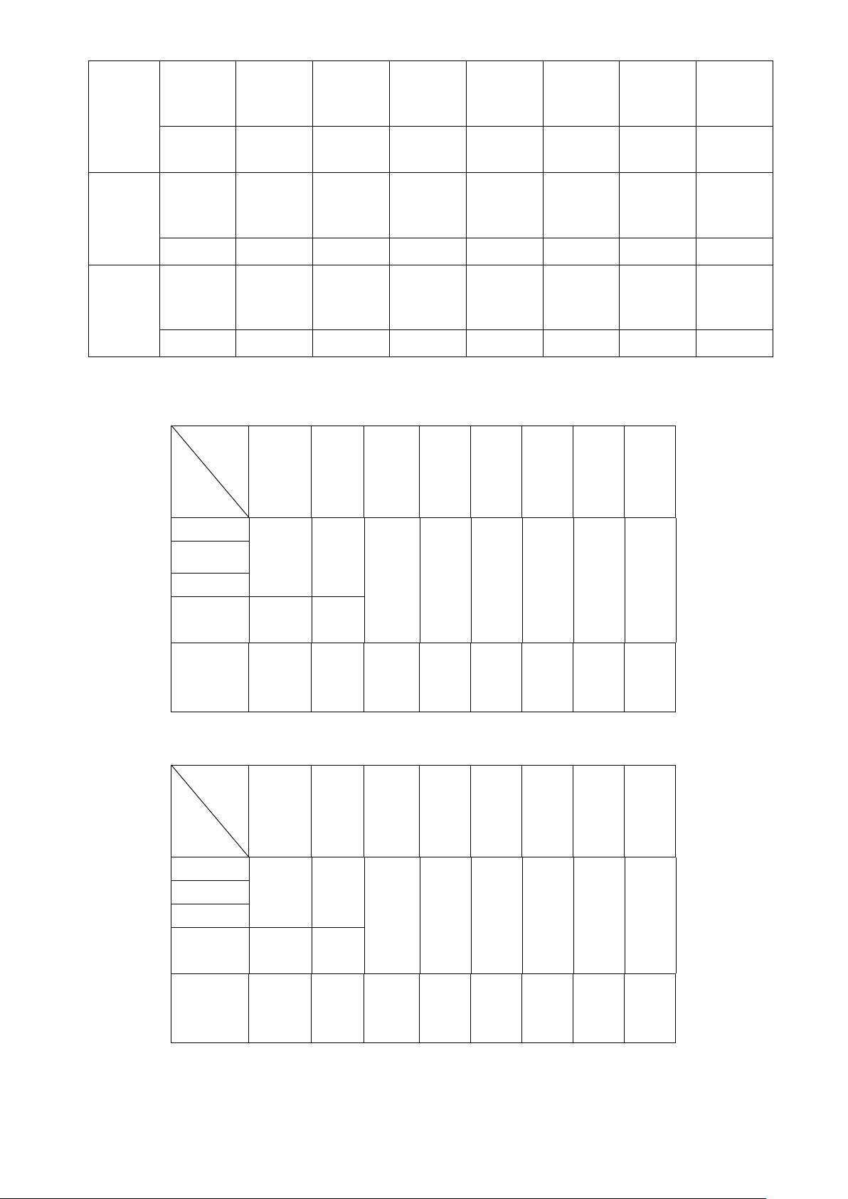
5. LCR Measurement:
Z Accuracy (Ae):
|Zx|
Freq.
DCR 2% ±1
100Hz
120Hz
1KHz
10KHz 5% ±1 2% ±1
100KHz
200KHz
20M ~
10M
(Ω)
NA 5% ±1 2% ±1 1% ±1 0.4% ±1 1% ±1 2% ±1 5% ±1
10M ~
1M
(Ω)
1% ±1 0.5% ±1 0.2% ±1 0.1% ±1 0.2% ±1 0.5% ±1 1% ±1
1M ~
100K
(Ω)
100K ~
10K
(Ω)
10K ~
Note:
1. The accuracy applies when the test level is set to 1Vrms.
2. Ae multiplies 1.25 when the test level is set to 250mVrms.
3. Ae multiplies 1.50 when the test level is set to 50mVrms.
4. When measuring L and C, multiply Ae by
: Ae is applied only when the test level is set to 1Vrms.
if the Dx>0.1.
1K
(Ω)
1K ~ 100
(Ω)
100 ~ 1
(Ω)
1 ~ 0.1
(Ω)
Page 8

7
C Accuracy:
NA
NA
100Hz
79.57pF
|
159.1pF
159.1pF
|
1.591nF
1.591nF
|
15.91nF
15.91nF
|
159.1uF
159.1nF
|
1.591uF
1.591uF
|
15.91uF
15.91uF
|
1591uF
1591uF
|
15.91mF
120Hz
1KHz
10KHz
100KHz
2% ± 1
66.31pF
|
132.6pF
2% ± 1
7.957pF
|
15.91pF
2% ± 1
0.795pF
|
1.591pF
5% ± 1
NA 0.159pF
1% ± 1 0.5% ± 1 0.2% ± 1 0.1% ± 1 0.2% ± 1 0.5% ± 1 1% ± 1
132.6pF
1.326nF
1% ± 1 0.5% ± 1 0.2% ± 1 0.1% ± 1 0.2% ± 1 0.5% ± 1
15.91pF
159.1pF
1% ± 1 0.5% ± 1 0.2% ± 1 0.1% ± 1 0.2% ± 1 0.5% ± 1
1.591pF
15.91pF
2% ± 1 0.5% ± 1 0.2% ± 1 0.1% ± 1 0.2% ± 1 0.5% ± 1
1.591pF
5% ± 1 2%± 1 1%± 1 0.4%± 1 1%± 1 2%± 1 5% ± 1
|
|
|
|
1.326nF
|
13.26nF
159.1pF
|
1.591nF
15.91pF
|
159.1pF
1.591pF
|
15.91pF
13.26nF
|
132.6nF
1.591nF
|
15.91nF
159.1pF
|
1.591nF
15.91pF
|
159.1pF
132.6nF
|
1.326uF
15.91nF
|
159.1nF
1.591nF
|
15.91nF
159.1pF
|
1.591nF
1.326uF
|
13.26uF
159.1nF
|
1.591uF
15.91nF
|
159.1nF
1.591nF
|
15.91nF
13.26uF
|
1326uF
1.591uF
|
159.1uF
159.1nF
|
15.91uF
15.91nF
|
1.591uF
1326uF
|
13.26mF
1% ± 1
159.1uF
|
1.591mF
1% ± 1
15.91uF
|
159.1uF
1% ± 1
1.591uF
|
15.91uF
200KHz
L Accuracy:
100Hz
120Hz
1KHz
NA 0.079pF
0.795pF
5% ± 1 2%± 1 1%± 1 0.4%± 1 1%± 1 2%± 1 5% ± 1
31.83KH
|
15.91KH
2% ± 1
26.52KH
|
13.26KH
2% ± 1
3.183KH
|
1.591KH
2% ± 1
15.91KH
1591H
1% ± 1 0.5% ± 1 0.2% ± 1 0.1% ± 1 0.2% ± 1 0.5% ± 1
13.26KH
1326H
1% ± 1 0.5% ± 1 0.2% ± 1 0.1% ± 1 0.2% ± 1 0.5% ± 1
1.591KH
159.1H
1% ± 1 0.5% ± 1 0.2% ± 1
0.795pF
|
|
|
|
|
7.957pF
1591H
|
159.1H
1326H
|
132.6H
159.1H
|
15.91H
7.957pF
|
79.57pF
159.1H
|
15.91H
132.6H
|
13.26H
15.91H
|
1.591H
79.57pF
|
795.7pF
15.91H
|
1.591H
13.26H
|
1.326H
1.591H
|
159.1mH
0.1% ± 1 0.2% ± 1
795.7pF
|
7.957nF
1.591H
|
159.1mH
1.326H
|
132.6mH
159.1mH
|
15.91mH
7.957nF
|
795.7nF
159.1mH
|
1.591mH
132.6mH
|
1.326mH
15.91mH
|
159.1uH
0.5%
± 1
795.7nF
|
7.957uF
1.591mH
|
159.1uH
1% ± 1
1.326mH
|
132.6uH
1% ± 1
159.1uH
|
15.91uH
1% ± 1
Page 9
8
10KHz
NA
NA
100K ~
100K ~
318.3H
|
159.1H
5% ± 1
159.1H
|
15.91H
2% ± 1 0.5% ± 1 0.2% ± 1 0.1% ± 1 0.2% ± 1 0.5% ± 1
15.91H
|
1.591H
1.591H
|
159.1mH
159.1mH
|
15.91mH
15.91mH
|
1.591mH
1.591mH
|
15.91uH
15.91uH
|
1.591uH
1% ± 1
100KHz
200KHz
D Accuracy:
31.83H
|
15.91H
15.91H
|
7.957H
|Zx|
Freq.
100Hz ±0.020 ±0.010 ±0.005 ±0.002 ±0.002 ±0.002 ±0.005 ±0.010
120Hz
1KHz
10KHz ±0.050 ±0.020
15.91H
|
1.591H
5% ± 1 2%± 1 1% ± 1 0.4% ± 1 1% ± 1 2%± 1 5% ± 1
7.957H
|
795.7mH
5% ± 1 2%± 1 1% ± 1 0.4% ± 1 1% ± 1 2%± 1 5% ± 1
20M ~
10M
(Ω)
1.591H
|
159.1mH
795.7mH
|
79.57mH
10M ~
1M
(Ω)
159.1mH
15.91mH
79.57mH
7.957mH
1M ~
100K
(Ω)
|
|
10K
(Ω)
15.91mH
|
1.591mH
7.957mH
|
795.7uH
10K ~
1K
(Ω)
1.591mH
159.1uH
795.7uH
79.57uH
1K ~
100
(Ω)
|
|
100 ~ 1
(Ω)
159.1uH
|
1.591uH
79.57uH
|
0.795uH
1 ~ 0.1
(Ω)
1.591uH
|
0.159uH
0.795uH
|
0.079uH
θ Accuracy:
100KHz
200KHz
|Zx|
Freq.
100Hz ±1.046 ±0.523 ±0.261 ±0.105 ±0.105 ±0.105 ±0.261 ±0.523
120Hz
1KHz
10KHz ±2.615
100KHz
200KHz
NA ±0.050 ±0.020 ±0.010 ±0.004 ±0.010 ±0.020 ±0.050
20M ~
10M
(Ω)
NA ±2.615 ±1.046 ±0.409 ±0.209 ±0.409 ±1.046 ±2.615
10M ~
1M
(Ω)
±1.046
1M ~
100K
(Ω)
10K
(Ω)
10K ~
1K
(Ω)
1K ~
100
(Ω)
100 ~ 1
(Ω)
1 ~ 0.1
(Ω)
Page 10

9
Z Accuracy:
1
2
1 Dx+
Ω=
−
⋅⋅⋅⋅
=
⋅⋅⋅
=
1590
9
10100
3
102
1
2
1
π
π
Cxf
Zx
LxfZx ⋅⋅⋅=
π
2
2
1 Dx+
Ω=
−
⋅⋅⋅=
⋅⋅⋅
=
283.6
3
10
3
102
2
π
π
LxfZx
As shown in table 1.
C Accuracy:
=
π
2
CAe = Ae of C
f : Test Frequency (Hz)
Cx : Measured Capacitance Value (F)
|Zx| : Measured Impedance Value (Ω)
Accuracy applies when Dx (measured D value) ≤ 0.1
When Dx > 0.1, multiply C
Example:
Test Condition:
Frequency : 1KHz
Level : 1Vrms
DUT : 100nF
Then
CxfZx⋅⋅⋅
Ae
by
Refer to the accuracy table, get CAe=±0.1%
L Accuracy:
LAe = Ae of L
f : Test Frequency (Hz)
Lx : Measured Inductance Value (H)
|Zx| : Measured Impedance Value (Ω)
Accuracy applies when Dx (measured D value) ≤ 0.1
When Dx > 0.1, multiply L
Example:
Test Condition:
Frequency : 1KHz
Level : 1Vrms
DUT : 1mH
Then
by
Ae
Refer to the accuracy table, get L
= ±0.5%
Ae
Page 11

10
ESR Accuracy:
100
Ae
Xx
Ae
ESR ⋅±=
Cxf
LxfXx
⋅⋅⋅
=⋅⋅⋅=
π
π
2
1
2
Ω=
−
⋅⋅⋅⋅
=
⋅⋅⋅
=
1590
9
10100
3
102
1
2
1
π
π
Cxf
Zx
Ω±=⋅±= 59.1
100
Ae
Xx
Ae
ESR
100
Ae
Ae
D ±=
Ω=
−
⋅⋅⋅⋅
=
⋅⋅⋅
=
1590
9
10100
3
102
1
2
1
π
π
Cxf
Zx
002.0
100
±=⋅±=
Ae
Ae
D
ESRAe = Ae of ESR
f : Test Frequency (Hz)
Xx : Measured Reactance Value (Ω)
Lx : Measured Inductance Value (H)
Cx : Measured Capacitance Value (F)
Accuracy applies when Dx (measured D value) ≤ 0.1
Example:
Test Condition:
Frequency : 1KHz
Level : 1Vrms
DUT : 100nF
Then
Refer to the accuracy table, get
=±0.1%,
C
Ae
D Accuracy:
DAe = Ae of D measurement value
Accuracy applies when Dx (measured D value) ≤ 0.1
When Dx > 0.1, multiply Dx by (1+Dx)
Example:
Test Condition:
Frequency : 1KHz
Level : 1Vrms
DUT : 100nF
Then
Refer to the accuracy table, get
=±0.1%,
C
Ae
Page 12

11
Q Accur acy :
DeQx
DeQx
Ae
Q
⋅
⋅
±=
1
2
1<⋅ DeQx
Ω=
−
⋅⋅⋅=
⋅⋅⋅
=
283.6
3
10
3
102
2
π
π
LxfZx
005.0
100
±=⋅±=
Ae
De
1.01
2
1
2
±=⋅
⋅
±=
DeQx
DeQx
Ae
Q
100
Ae
π
180
⋅=
Ae
θ
Ω=
−
⋅⋅⋅⋅
=
⋅⋅⋅
=
1590
9
10100
3
102
1
2
1
π
π
Cxf
Zx
deg057.0
100
1.0180
100
180
±=⋅±=
⋅±=
π
π
θ
Ae
Ae
QAe = Ae of Q measurement value
Qx : Measured Quality Factor Value
De : Relative D Accuracy
Accuracy applies when
Example:
Test Condition:
Frequency : 1KHz
Level : 1Vrms
DUT : 1mH
Then
Refer to the accuracy table, get
=±0.5%,
L
Ae
If measured Qx = 20
Then
θ Accuracy:
Example:
Test Condition:
Frequency : 1KHz
Level : 1Vrms
DUT : 100nF
Then
Refer to the accuracy table, get
=±0.1%,
Z
Ae
Page 13

12
Testing Signal:
Level Accuracy : ± 10%
Frequency Accuracy : 0.1%
Output Impedance : 100Ω ± 5%
General:
Temperature : 0°C to 40°C (Operating)
-20°C to 70°C (Storage)
Relative Humidity : Up to 85%
AC Power : 110/220V, 60/50Hz
Dimensions : 300mm x 220mm x 150mm (L x W x H) 11.8” x 8.7” x 5.9”
Weight : 4500g
Considerations
When LCR measurement mode is selected, the following factors shall be considered.
Test Frequency T he test frequenc y is user selec table and can be cha nged. Generall y, a 1 KHz test signal or
higher is used to m easure capacitors that are 0.01uF or sm aller and a 120Hz t est signal is used f or capacito rs
that are 10uF or larger. Typically a 1 KHz test signal or higher is used to measure inductors that are used in audio
and RF (radio frequ ency) circuits. This is because these k inds of inductors op erate at higher f requencies and
require that they shal l be measured at a higher fr equency. Generall y, inductors with induc tances below 2mH
should be measured at t est frequency of 1 KHz or h igher and inductors above 200H should be measured at
120Hz or lower.
It is best to check with the c omponent manufactur ers’ data sheet to determine the best test fr equency for the
device.
Charged Capacitors Always discharge an y capacitor prior to making a measurement since a charged
capacitor may seriously damage the meter.
Effect Of High D on Accuracy A low D (Dissipation Factor) reading is desirable. Electrolytic capacitors
inherently have a higher di ssipation factor due to their normally hi gh internal leakage characteris tics. If the D
(Dissipation Factor) is excessive, the capacitance measurement accuracy may be degraded.
It is best to chec k with the component manuf acturers’ data sheet t o determ ine the d esirable D valu e of a good
component.
Measuring Capacitance of Cables, Sw itches or Other Parts Measuring the c apacitance of c oaxial c able s is
very useful in determ ining the actual length of the cable. Most m anufacturer specifications list th e amount of
capacitance per foot of cable and therefore the length of the cable can be determined by measuring the
capacitance of that cable.
For example: A manufacturers, spec ification calls out a certain cab le, to have a c apacitance of 10 pF per foot,
After measuring the cable, a capacitance reading of 1.000nF is displayed. Dividing 1000pF (1.000 nF) by 10 pF
per foot yields the length of the cable to be approximately 100 feet.
Even if the manufacturers’ specification is not known, the capacitance of a measured length of cable (such as 10
feet) can be used to deter m ine t he capac itance per f oo t . Do n ot us e t oo s hort l en gth such as one foot, beca use
any error becomes magnified in the total length calculations.
Sometimes, the affecting s tray capacitance of switches , interconnect cables, circ uit board foils, or other parts,
could be critical to circuit design, or must be repeatable from one unit to another.
Series Vs Parallel Measurement (for Inductors) The series mode displays the more accurate measurement in
most cases. The series equivalent mode is essential f or obtaining an accurate Q reading of low Q induc tors.
Where ohm ic losses are most significant, th e series equivalent m ode is preferred. However, there are cases
Page 14

13
where the parallel equivalent mode may be more appropriate. For iron core inductors operating at higher
frequencies where hysteresis and eddy currents become significant, m easurement in the parallel equivalent
mode is preferred.
1.4 Accessories
Operating Manual 1 pc
AC Power Cord 1 pc
Kelvin Clip 1 pc
DMM Test Leads 1 pc
Page 15

14
2. Operation
2.1 Ph ysical Des crip tio n
1. Primary Parameter Display 2. Secondary Parameter Display
3. L/C/Z/DCR Function Key 4. DCA/ACA Function Key
5. Measurement Frequency Key 6. LCUR Terminal
7. Measurement Level Key 8. Range Hold Key
9. Model Number 10. LPOT Terminal
11. D/Q/θ/ESR Function Key 12. HPOT Terminal
13. Open Calibration Key 14. DCV/ACV Function Key
15. Rela ti ve Key 16. HCUR Terminal
17. Short Calibration Key 18. Diode/Continuity Function Key
19. Remote Function Key
21. P ower Swit ch
23. AC Power
25. A Terminal
20. COM T erminal
22. V/Diode/Continuity Terminal
24. USB Port
26. 2A Fuse
Page 16

15
2.2 Making Measurement
2.2.1 Open and Short Calibration The 889B provides open/s hort calibr ation capabil ity so the user c an get better accur acy in meas uring high and
low impedance. We recomm end that the user per form open/short calibr ation if the test leve l or frequency has
been changed.
Open Calibration
First, remaining the measurement terminals at the open status, press the Open key then the LCD will display:
This calibration takes about 15 seconds. After it is finished, the 889B will beep to show that the calibration is
done.
Short Calibration
To perform the short calibration, insert the Shor ting Bar into the measur ement terminals. Pr ess the Short key
then the LCD will display:
This calibration takes about 15 seconds. After it is fin ished, the 889B will beep to sho w that the calibration is
done.
2.2.2 Relative Mode The relative mode lets t he user to m ak e a quick sort of a bunch of c om ponents. First, insert the stand ard va lue
component to get the standard value reading. (Approximately 5 seconds to get a stable reading.) Then, press the
Relative key, the primary display will reset to zero. Remove the standard value component and insert the
unknown component, the LCD will show the value that is the difference between the standard value and unknown
value.
2.2.3 Range Hold T o set the range hold, insert a standard component in that measurement range. (Approximately 5 seconds to get
a stable reading.) Then, by pressing the Range Hold key it will hold the range within 0.5 to 2 times of the current
measurement range. When the Range Hold is pressed, the LCD will display:
Page 17

16
2.2.4 DC Resistance Measurement The DC resistance measurement measures the resistance of an unknown component by 1VDC. Press the
L/C/Z/DCR key to select the DCR measurement. The LCD will display:
2.2.5 AC Impedance Measurement
The AC impedance measurement measures the Z of an unknown device. Press the L/C/Z/DCR key to se lect the
Z measurement. The LCD will display:
The testing level and frequency can be selected by pressing the Level key and Freq key, respectively.
2.2.6 Capacitance Measurement To measure the capacitance of a component, users may be able to press the L/C/Z/DCR key to select either Cs
(Serial Mode) or C p ( Par a llel Mod e) measurement mode. If t he s erial mode (Cs ) i s selec te d, t he D , Q and ESR
can be shown on the secondary display. If the parallel mode (Cp) is selected, only the D and Q can be shown on
the secondary display. The following shows some examples of capacitance measurement:
The testing level and frequency can be selected by pressing the Level key and Freq key, respectively.
2.2.7 Inductance Measurement
Press the L/C/Z/DCR key to select Ls or Lp mode for measuring the inductance in serial mode or parallel mode.
If the serial mode (Ls) is selected, the D, Q and ESR can be shown on the secondary display . If the parallel mode
(Lp) is selected, only the D and Q can be shown on the secondary display. The following shows some examples
of inductance measurement:
The testing level and frequency can be selected by pressing the Level key and Freq key, respectively .
Page 18

17
3. Operation Modes
There are four operation modes in the 889B. They are Normal, Binning, Remote and Remote Bi nning modes.
By pressing the Remote button, users can select one of the 4 operation modes above.
Normal Mode:
The Normal mode is the default operation mode when power on. It is a local mode that the 889B is controlled
by the keypads and th e results of the measurement will be s ent to both LCD display and a remote USB
equipped PC through the build-in USB port.
Binning Mode:
The Binning mode is reserved for future use (such as GPIB). Currently, it is set to work the same way as the
Normal mode that receives commands from the keypads and sends the results of measurement to both LCD
display and a remote PC through the USB port.
Remote Binning Mode:
In the Remote Binning mode, the “R MT Bin” on the LCD will be lit, the o peration of 889B is control led by a
remote USB equipped PC or term inal, and t he res ults of the m easur ement will be sim ultaneously se nt t o t h e
local LCD display and remote workstation through the USB port.
In this mode all functional keypads except Remote button are locked.
Remote Binning m ode is opened for users to design your own private, fast an d high efficient application
programs. Users can design a server or driver (any software component that can do server’s job) with Graphic
interface, OSI network model, and powerful interpreter built in it to support Graphic display, Network
connectivity, structure command (SCPI, IEEE488 etc.) interpretations, and let it be a bridge between a higher
level application program such as VB , VISUAL C++, EXCEL , ACCESS etc. and the 889B. It is d escribed in
the following figure.
Server:
Model
889B
COM, DCOM, ATL,
CONTROL,
AUTOMATION EXE
Built in:
Graphic interface,
OSI network model,
and/or powerful
Interpreter or Parser
VB, VISUAL
C++, EXCEL,
ACCESS etc.
The communication protocol between the 889B and a remote USB equipped PC is described as follows.
1. The commands that will be sent from a remote PC to the 889B are use d to set-up the machine to a
selected measurement mode.
The command syntax is:
MOD current-state-code
It always starts with MOD follows by a space and then the current state code. The current state code that
is defined in the table below is 3 bytes (24 bits) long, bit-23, 22, 21… bit-0, where bit-23 is the MSB and bit-0
is the LSB.
Page 19

18
bit position LCR DC/AC V/A
Bit 2 – Bit 0
(test freq)
Reserved
001
120 Hz
011
10K Hz
101
200K Hz
111
Reserved
Bit 4 – Bit 3
00
50 mVrms
10
1 Vrms
Bit 5
Reserved
1
Reserved
Reserved
Bit 6
0
Relative
Relative
Bit 7
1
Normal
Normal
Bit 10 – Bit 8
000
Lp
010
Cp
100 Z
110
Reserved
Bit 12 – Bi t 11
Reserved
01 Q
11
ESR
Bit 16 – Bit 13
0000
RH nH
Reserved
0010
RH mH
RH V, A
0100
RH pF
0110
RH uF
1000
RH F
1010
RH K-Ohm
1100
Reserved
000 100 Hz
010 1K Hz
100 100K Hz
110 Reserved
(test level) Reserved
01 250 mVrms
11 Reserved
0 Default Default
1 Normal Normal
0 Calibration Calibration
Reserved
001 Ls
011 Cs
101 DCR
111 Reserved
00 D
10 DEG
0001 RH uH RH mV, mA
0011 RH H Reserved
0101 RH nF
0111 RH mF
1001 RH Ohm
1011 RH M-Ohm
Page 20

19
1101
1110
1111
Auto-Ranging
Auto-Ranging
Bit 17
Bit 21 – Bit 18
0100
Diode
0110
DCA
Bit 23 – Bit 22
00
10
02
09
M-B0
M-B1
M-B2
M-B3
S-B0
S-B1
S-B2
S-B3
CS
02
03
M-B0
M-B1
M-B2
M-B3
CS
0 Short Cal Short Cal
1 Open Cal Reserved
Measurement Modes
0000 Reserved
0001 LCR
0010 DCV
0011 ACV
0101 Continuity
0111 ACA
Others Reserved
Reserved
01
11
For example: if LCR f unc tion, Cp with D measurement m ode is s elected in Aut o-ranging with Relative and
Open/Short Calibration are turned off and test signal is 1 Vrms in 1 KHz, then the command is as following:
MOD 000001111110001011010010
2. The results of the m easurem ent that will be sent from the 889B to a r emote PC will be packed in either
7-byte or 11-byte format.
When dual data (such as Cp with D) will be sent, the data is packed in 11-byte format shown as following:
Lead_code1 : 02
Lead_code2 : 09
Data_code : 8-byte long; two 32-bit floating point number format; the first 4-byte is the main reading (Cp)
and the second 4-byte is the secondary reading (D)
Checksum : -((02+09+data_code) && 0x00FF)
where M-Bx and S-Bx are the four bytes floating point format of main and secondary reading which is sent
from the lowest byte first.
When only main reading (such as DCR) will be sent, the data is packed in 7-byte format described below:
Lead_code1 : 02
Lead_code2 : 03
Data_code : 4 bytes long; the 32-bit floating point format of the main reading
Checksum : -((02+03+data_code) && 0x00FF)
When only secondar y readi ng (such as DCV) will be s ent, the data is packed in 11-byte format desc ribed
below:
Lead_code1 : 02
Lead_code2 : 09
Page 21

20
Data_code : 8 bytes long; two 32-bit floating point format of the secondary reading
02
09
S-B0
S-B1
S-B2
S-B3
S-B0
S-B1
S-B2
S-B3
CS
Checksum : -((02+09+data_code) && 0x00FF)
Remote Mode:
When in the Remote mode, the “RMT” on the LCD will be lit and the 889B is capable of communicating to
remote USB equipped PC or terminal through the build-in USB port. The connection setting is as follow:
Transmission Mode : Half Duplex
Baud Rate : 9600
Parity Bit : None
Data Bits : 8
Stop Bit : 1
Handshake : None
In this mode, the LCD display and all keypads except the Remote button will b e locked. And the external
program through the USB port controls the operation of the 889B.
3.1 Remote Mode Command Syntax
The command syntax of Models 4090 is as following:
COMMAND(?) (PARAMETER)
The format of COMMAND and PARAMETER is as following:
1. There is at least one space between COMMAND and PARAMETER.
2. The PARAMETER should use only ASCII string not num er ical code.
3. Value parameter can be integer, floating or exponent with the unit. For example:
50mV
0.05V
5.0e1mV
4. The question mark (?) at the end of COMMAND means a query or a measuring command. For example:
“CpD” sets the measurement mode to Cp and D.
“CpD?” sets the measurement mode to Cp and D as well as measures the values and send them back.
5. The COMMAND and PARAMETER can be either upper or lower case. But the unit to describe the value in the
PARAMETER should have different between milli (m) and mega (M). For example:
1mV equals 0.001V.
1MV equals 1000000V.
6. The “end of command” character should be placed at the end. There are:
ASCII CR (0DH) or
ASCII LF (0AH)
3.2 Remote Mode Commands
Measurement Setting (or Querying) Command
The following measurement mode-setting and the query commands are supported in the 889B. When a mode-setting
command is entered the 889B will return “OK” after setting is complet e. When query comma nd is entere d, the 889B will send
back the values of measurement.
DCR(?) DC resistance measurement mode setting or querying command.
CpRp(?) Parallel capacitance and parallel resistance measurement mode setting or querying command.
CpQ(?) Parallel capacitance and quality factor measurement mode setting or querying command.
CpD(?) Parallel capacitance and dissipation factor measurement mode setting or querying command.
Page 22

21
CsRs(?) Serial capacitance and serial resistance measurement mode setting or querying command.
CsQ(?) Serial capacitance and quality factor measurement mode setting or querying command.
CsD(?) Serial capacitance and dissipation factor measurement mode setting or querying command.
LpRp(?) Parallel inductance and parallel resistance measurement mode setting or querying command.
LpQ(?) Parallel inductance and quality factor measurement mode setting or querying command.
LpD(?) Parallel inductance and dissipation factor measurement mode setting or querying command.
LsRs(?) Serial inductance and serial resistance measurement mode setting or querying command.
LsQ(?) Serial inductance and quality factor measurement mode setting or querying command.
LsD(?) Serial inductance and dissipation factor measurement mode setting or querying command.
RsXs(?) Serial resistance and serial reactance measurement mode setting or querying command.
RpXp(?) Parallel resistance and parallel reactance measurement mode setting or querying command.
ZTD(?) Impedance and angle (Deg) measurement mode setting or querying command.
ZTR(?) Impedance and angle (Rad) measurement mode setting or querying command.
DCV(?) DC Voltage measurement mode setting or query command.
ACV(?) AC Volt age measurement mode setting or query command.
DCA(?) DC Current measurement mode setting or query command.
ACA(?) AC Current measurement mode setting or query command.
Example:
CPD (set to Cp-D me asur e ment mo de)
OK
CPD?
0.22724 0.12840 (return values)
DCR?
5.1029 (return value)
*IDN?
Query the identity of the 889B. This command is used to identify the basic information of 889B. The return value
has four fields separated by comma (,). The total length will not greater than 100 characters. The four fields are:
1. Manufacturer Name
2. Model Number
3. Serial Number
4. Firmware Version Number
Example:
*IDN?
B&K PRECISION CORP. MODEL889B,123456789,4.096
*RST
Reset the 889B to the power on default status. The default status is:
1KHz 1Vrms CpD uF
After the 889B is reset, it will return the identity string back.
ASC
Set the format of the return value. This command sets the ASCII string return or the numerical code.
PARAMETER:
ON ASCII string
OFF Numerical code
Page 23

22
Example:
ASC ON
OK (return)
FREQ?
1KHz (return)
ASC OFF
OK (return)
FREQ?
CORR OPEN
Perform the open calibration. This command sets the 889B to do the open calibration. After the calibration is done,
the 889B will return the “OK” string back.
2 (return)
CORR SHORT
Perform the short calibration. This command sets the 889B to do the short calibration. After the calibration is done,
the 889B will return the “OK” string back.
FREQ(?) PARAMETER
Set (query) the measurement frequency.
FREQ PARAMETER
Set the measurement frequency according to the parameter. When setting command is entered, the 889B will
return “OK” string after setting is done.
PARAMETER:
ASCII string Numerical code
100Hz 0
120Hz 1
1KHz 2
10KHz 3
100KHz 4
200KHz 5
Example:
FREQ 100KHz
OK (return)
FREQ?
Return the current measurement frequency setting.
Example:
ASC ON
OK
FREQ?
1KHz (return value)
ASC OFF
OK
FREQ?
2 (return value)
LEV(?) PARAMETER
Set (query) the measurement level.
LEV PARAMETER
Page 24

23
Set the measurement level according to the parameter. When setting is done the 889B will return “OK” string.
PARAMETER:
ASCII string Numerical code
1VDC 0
1Vrms 1
250mVrms 2
50mVrms 3
Example:
LEV 1V
OK
LEV?
Return the current measurement level setting.
Example:
ASC ON
OK
LEV?
1Vrms (return value)
ASC OFF
OK
LEV?
1 (return value)
MODE?
Query the measurement mode. If in LCR measurement mode, six fields will be returned.
1. Frequency
2. Level
3. Measurement mode
4. Unit of primary display
5. Unit of secondary display
The existence of field 5 depends on the measurement mode. For example, there’s no field 5 if the measurement
mode is DCR. The separation between fields is space (ASCII 20H).
Example:
ASC ON
OK
CPD
OK
MODE?
1KHz 1Vrms CpD uF (return value)
ASC ON
OK
CPRP
OK
MODE?
1KHz 1Vrms CpRp uF Ohm (return value)
If in Voltage measurement mode, three fields will be returned.
1. Measurement mode
2. Unit of primary display
Page 25

24
Example:
ASC ON
OK
DCV
OK
MODE?
DCV V (return value)
RANG mV
OK
MODE?
DCV mV (return value)
RANG(?) PARAMETER
Set (query) the measurement unit.
RANG PARAMETER
Set the measurement unit according to the parameter. “OK” string will be returned when setting is complete.
PARAMETER:
ASCII string Numerical code
pF 0
nF 1
uF 2
mF 3
F 4
nH 8
uH 9
mH 10
H 11
KH 12
mOhm 17
Ohm 18
KOhm 19
MOhm 20
mV 21
V 22
mA 23
A 24
Example:
RANG pF
OK
RANG?
Return the current measurement unit setting.
Example:
ASC ON
OK
RANG?
pF (return value)
Page 26

25
ASC OFF
OK
RANG?
0 (return value)
READ?
Return the measurement value. This command will perform a measurement according to the current
measurement mode and return the measured value.
Example:
CPD
OK
READ?
0.22724 0.12840 (return value)
DCR
OK
READ?
5.1029 (return value)
The “DCR”, “DCV”, and “ACV” measurements will send only one measured value. The other measurement
modes will send two measured values separated by space (ASCII 20H).
Page 27

26
4. Application
R
H
CUR
H
POT
DUT
(b) BLOCK DIAGRAM
DUT
V
A
Co
o
L
o
R
o
L
o
(a) CONNECTION
(c) TYPICAL IMPEDANCE MEASUR EMENT RANGE(£[)
2T
1m 10m 100m 1 10 1K 10K 100K 1M100 10M
L
POT
L
CUR
DUT
V
A
(d) 2T CONNECTION WITH SHILDING
H
CUR
H
POT
DUT
(b) BLOCK DIAGRAM
DUT
V
A
Co
R
o
L
o
R
o
L
o
Co doesn't
effect
measurement
result
(a) CONNECTION
(c) TYPICAL IMPEDANCE MEASUREMENT RANGE(£[)
3T
1m 10m 100m 1 10 1K 10K 100K 1M100 10M
L
POT
L
CUR
4.1 Test Leads Connecti o n
Auto balancing bridge has four terminals (H
CUR
POT
CUR
and L
) to connect to the device under test (DUT).
POT
, H
, L
It is important to understand what connection method will affect the measurement accuracy.
2-Terminal (2T)
2-Terminal is the easiest way to connect the DUT, but it contents m any errors that are the inductance and
resistance as well as the parasitic capacitance of the test leads (Figure 4.1). Due to these errors in
measurement, the effective impedance measurement range will be limited at 100Ω to 10KΩ.
Figure 4.1
3-Terminal (3T)
3-Terminal uses c oaxial cable to reduce the effect of the parasitic capacitor (Figure 4.2). The shield of the
coaxial cable should connect to guard of the instrument to increase the measurement range up to 10MΩ.
Figure 4.2
4-Terminal (4T)
4-T er minal connection reduces the effect of the test lead resistance (Figure 4.3). This connection can improve
the measurement range down to 10mΩ. However, the effect of the test lead inductance can’t be eliminated.
Page 28

27
HCUR
HPOT
DUT
(b) BLOCK DI AGRAM
DUT
V
A
(a) CONNECTION
(c) TYPICAL IMPEDANCE MEASUREMENT RANGE (£[)
4T
1m 10m 100m 1 10 1K 10K 100K 1M100 10M
LPOT
LCUR
(d) WRO NG 4T CONNECTION
H
POT
DUT
(b) BLOCK DIAGRAM
(a) CONNECTION
(c) TYPICAL I MPEDANCE MEASUREMENT RANGE (£[)
5T
1m 10m 100m 1 10 1K 10K 100K 1M100 10M
H
CUR
DUT
V
A
DUT
V
A
L
POT
L
CUR
Figure 4.3
5-Terminal (5T)
5-Terminal connect ion is the combination of 3T and 4T (Figure 4.4). It has four coaxial cables. Due to the
advantage of the 3T and 4T, this connection can widely increase the measurement range for 10mΩ to 10MΩ.
4-Terminal Path (4TP)
4-T erminal Path connection solves the problem that caused by the test lead inductance. 4TP uses four coaxial
cables to isolate the current path and the voltage sense cable (Figure 4.5). The return current will flow through
the coaxial cable as well as t he shiel d. Ther efor e, the m agnetic f lux that g enera ted b y interna l conduc tor will
cancel out the m agnetic flux generated by extern al conductor (shield). The 4TP conn ection increases the
measurement range from 1mΩ to 10MΩ.
Figure 4.4
Page 29

28
(b) BLOCK DIAGRAM
(a) CONNECTION
DUT
V
A
(c) TYPICAL IMPEDANC E
MEASUREMENT RANGE(£[)
4T
1m 10m100m 1 10 1K 10K 100K 1M100 10M
H
POT
DUT
H
CUR
L
CUR
L
POT
H
POT
DUT
H
CUR
L
CUR
L
POT
(d) 4T CONNECTION WITH SHILDING
(a) Parastic Effect
H
CUR
HPOT
LPOT LCUR
Cd
Connection
Point
DUT
C
h C
l
Ground
(b) Guard Plant reduces
Parastic Effect
HCUR
HPOT LPOT
L
CUR
Guard
Plant
Figure 4.5
Eliminating the Effect of the Parasitic Capacitor
When measuring the high impedance com ponent (i.e. low capacitor), the parasitic capacitor becom es an
important issue (Figure 4.6). In f igure 4.6(a) , the parasi tic capacitor C d is parallel ed to DUT as well as the Ci
and Ch. To correct this problem, add a guard plane (Figure 4.6(b)) in between H and L terminals to break the
Cd. If the guard plane is connected to instrument guard, the effect of Ci and Ch will be removed.
4.2 Open/Short Compensation
For those precision im pedance-measuring instrum ents, the open and short compens ation need to be used to
reduce the parasitic effect of the tes t f ixtur e. The parasitic effect of the test f ixtur e c an be trea ted like the simple
passive components in figur e 4.7(a). When the DUT is open, the instrum ent gets the conductance Yp = Gp +
jωCp (Figure 4.7(b)). When the DUT is short, the instrument gets the impedance Zs = Rs + jωLs (Figure 4.7(c)).
After the open and short compensation, the 889B has Yp and Zs that can then be used for the real Zdut
calculation (Figure 4.7(d)).
Figure 4.6
Page 30

29
H
CUR
H
POT
L
CUR
L
POT
Zdut
C
o
R
s
L
s
G
o
Z
m
Redundant
Impedance
(Z
s
)
Parastic
Conductance
(Y
o
)
Parastic of the Test Fixture
(a) Parastic Effect of the Test Fixture
HCUR
HPOT
LCUR
LPOT
C
o
R
s
L
s
G
o
(b) OPEN Measurement
Y
o
OPEN
Y
o = Go + j£sCo
1
(Rs + j£s<< )
Go+j£sCo
H
CUR
H
POT
L
CUR
L
POT
C
o
R
s
L
s
G
o
(c) SHORT Measurement
Z
s
SHORT
Z
s
= R
s
+ j£sL
s
Z
m
Y
o
Zdut
Zm - Z
s
Zdut =
1-(Z
m
-Zs)Y
o
(d) Compensation Equation
Z
s
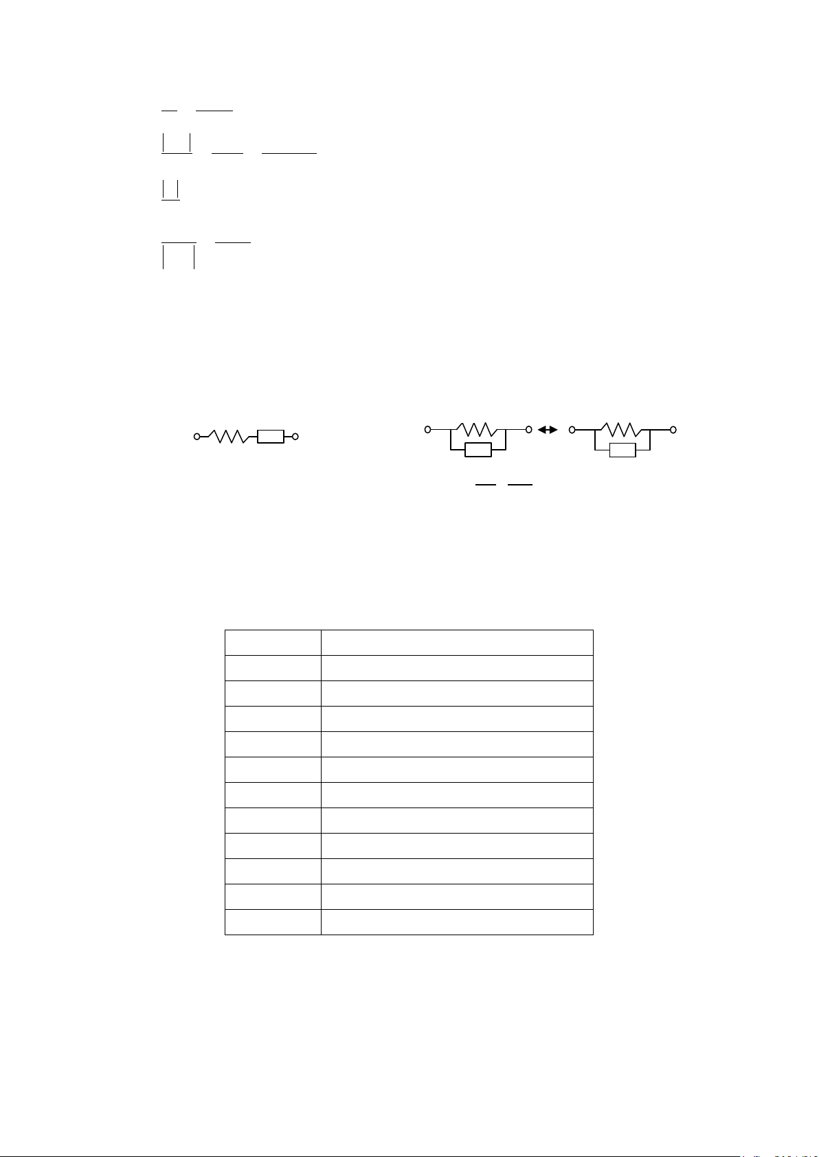
4.3 Selecting the Series or Parallel Mode
Figure 4.7
According to different measuring requirement, there are series and parallel modes to describe the
measurement results. It is depending on the high or low impedance value to decide what mode to be used.
Capacitor
The impedance and capacitance in the capacitor are negatively proportional. Therefore, the larger
capacitance means the low er im pedance, the s m aller capacitance m eans the hi gher im pedance. F igure 4.8
shows the equivalent circui t of capacitor. If the capacitance is small, the Rp is more important than the Rs . If
the capacitance is large, the Rs shouldn’t be avoided. He nce, it is properly to use parallel mode for low
capacitance measurement and series mode for high capacitance measurement.
Page 31

30
R
C
R
Effect
R
P
C
R
Effect
Figure 4.9
R
P
L
R
Effect
R
P
L
R
Effect
Small capacitor
(High impedance)
Large capacitor
(Low impedance)
P
S
No Effect
No Effect
S
Inductor
The impedance and inductance of a inductor are positively proportional when test frequency is fixed.
Therefore, the larger inductance equals to higher impedance and vice versa. Figure 4.9 shows the equivalent
circuit of inductor. When the induc tance is small, the Rs becom es more important than the R p. When the
inductance is large, the Rp s houl d be taking into considerati on. T her ef ore, it is properly using series mode to
measure an inductor with low inductance and parallel mode to measure an inductor with high inductance.
Large inductor
(High impedance)
Small inductor
(Low impedance)
No Effect
S
No Effect
S
Page 32

31
5. Limited THREE-Year Warranty
B&K Precision Corp. warrants to the original purchaser that its products and the component parts thereof, will be
free from defects in workmanship and materials for a period of th ree yea rs
B&K Precision Corp. will, without charge, repair or replace, at its option, defective product or component parts.
Returned product must be accompanied by proof of the purchase date in the form of a sales receipt.
To obtain warranty coverage in the U.S.A., this product must be registered by completing a warranty registration
form on our website
Exclusions: This warranty does not apply i n the event of misus e or abuse of the produc t or as a result of
unauthorized alterations or repairs. The warranty is void if the serial number is altered, defaced or
removed.
B&K Precision Corp. shall not be liable for any consequential damages, including without limitation damages
resulting from loss of use. Some states do not allow limitations of incidental or consequential damages. So the
above limitation or exclusion may not apply to you.
This warranty gives you specific rights and you may have other rights, which vary from state-to-state.
www.bkprecision.com within fifteen (15) days of purchase.
from date of purchase.
B&K Precision Corp.
22820 Savi Ranch Parkway
Yorba Linda, CA 92887
www.bkprecision.com
714-921-9095
 Loading...