

Page 1

Models
885 & 886
LCR METER
OPERATING
MANUAL
MANUAL DE INSTRUCCIÓNES
MEDIDOR LCR
Modelos 885 & 886
Find Quality Products Online at: sales@GlobalTestSupply.com
www.GlobalTestSupply.com
Page 2

Contents
1. INTRODUCTION ............................................................... 1
1.1 G
ENERAL
............................................................................. 1
MPEDANCE PARAMETERS
1.2 I
PECIFICATION
1.3 S
CCESSORIES
1.4 A
.................................................................... 6
.................................................................... 19
.................................................. 3
2. OPERATION ...................................................................... 21
2.1 P
HYSICAL DESCRIPTION
AKING MEASUREMENT
2.2 M
2.2.1 Battery Re placement ............................................................... 22
2.2.2 Battery Recharging/AC operation .......................................... 23
2.2.3 Open and Short Calibrati on ................................................... 24
2.2.4 Display Sp eed .......................................................................... 25
2.2.5 Relative Mode ......................................................................... 25
2.2.6 Range Hold.............................................................................. 25
2.2.7 DC Resistance Measurement .................................................. 26
2.2.8 AC Impedance Measurement .................................................. 26
2.2.9 Capacitance Measurement ..................................................... 26
2.2.10 Inductance Measurement ........................................................ 27
2.3 A
CCESSORY OPERATION
................................................... 21
................................................. 21
................................................... 28
4. APPLICATION .................................................................. 30
4.1 T
EST LEADS CONNECTION
PEN/SHORT COMPENSATION
4.2 O
ELECTING THE SERIES OR PARALLEL MODE
4.3 S
............................................... 30
.......................................... 35
.................. 37
5. LIMITED THREE-YEAR WARRANTY ...................... 37
6. SAFETY PRECAUTION .................................................
42
Find Quality Products Online at: sales@GlobalTestSupply.com
www.GlobalTestSupply.com
Page 3

1. Introduction
1.1 General
The B&K Precision Models 885 & 886 Synthesized In-Circuit
LCR/ESR Meter is a high accuracy hand held portable test
instrument used for measuring inductors, capacitors and resistors
with a basic accuracy of 0.2%. It i s the most advanced handheld
AC/DC impedance measurement instrument to date. The 885 or 886
can help engineers and student s to understand the character istic of
electronics components as well as being an essential tool on any
service bench.
The instrument is auto or manual ranging. Test frequencies of
100Hz, 120Hz, 1KHz 10KHz or 100KHz (886) may be selecte d on
all applicable ranges. The test voltages of 50mVrms, 0.25Vrms,
1Vrms or 1VDC (DCR only) may al s o be selected on all applicable
ranges. The dual display feature permits simultaneous
measurements.
Components can be measured in the series or parallel mode as
desired; the more standard method is automatically selected first but
can be overridden.
The Model 885 and 886 offers three useful modes for sorting
components.
The highly versatile Mode ls can perf orm virtua lly all the functions
of most bench type LCR bri dges. With a basic accuracy of 0.2%,
this economical LCR meter may be adequately substituted for a
1
Find Quality Products Online at: sales@GlobalTestSupply.com
www.GlobalTestSupply.com
Page 4

more expensive LCR bridge in many situations. The meter is
powered from two AA Batteries and is supplie d with an AC to DC
charging adapter and two AA Ni -Mh Rechargeabl e Batteries.
The instrument has applications in electronic engineering labs,
production facili ties, service shops, and schools. It can be used to
check ESR v alues of capacitors , sort values, selec t precision values,
measure unmarked and unknown i nductors, capacit ors or resistor s,
and to measure capacitance, inductance, or resistance of cables,
switches, circuit boar d foils, etc.
The key features are as following:
Te st condition:
Frequency : 100Hz / 120Hz / 1KHz / 10KHz /
1
100KHz (886)
Level : 1Vrms / 0.25Vrms / 50mVrms /
2.
1VDC (DCR only)
Measurement Parameters : Z, Ls, Lp , C s, C p , D C R ,
ESR, D, Q and
Basic Accu racy: 0.2%
Dual Liquid Crystal Display
Fast/Slow Measurement
Auto Range or Range Hold
Open/Short Calibrati on
Primary Parameters Display:
Z : AC Impedance
DCR : DC Resistance
Ls : Serial Inductance
Lp : Parallel Inductance
θ
2
Find Quality Products Online at: sales@GlobalTestSupply.com
www.GlobalTestSupply.com
Page 5

Cs : Serial Capacitance
Cp : Parallel Capacitance
Second Parameter Display:
θ
: Phase Angle
ESR : Equivalence Serial Resistance
D : Dissipati on Fact or
Q : Quality Factor
Combinations of Display:
θ
Serial Mode : Z –
Parallel M od e : Cp – D, Cp – Q, Lp – D, Lp – Q
1.2 Impedanc e Parameters
Due to the different test ing signal s on t he impedance mea surement
instrument, there are DC impedance and AC impedance. The
common digital multi -meter can only measure the DC impedance,
but the Model 885 can do both. It is a very important issue to
understand the impedance parameters of the electronic com ponent.
When we analysis the impedance by the impedance measurement
plane (Figure 1.1). It can be visualized by the rea l element on the
X-axis and the imaginary element on the y-axis. Thi s impedance
measuremen t plan e can also be seen as th e pola r coordin at es. Th e Z
is the magnitude and the
θ
, Cs – D, Cs – Q, Cs – ESR, Ls –
D, Ls – Q, Ls – ESR
is the phase of the impedance.
3
Find Quality Products Online at: sales@GlobalTestSupply.com
www.GlobalTestSupply.com
Page 6

( )
( )
( )
( )
( )
Ohm
Reactance
Resistance
Impedance
1
22
=Ω
=
=
=
==
+==
Ω∠=+=
−
S
S
s
s
s
sss
ss
X
R
Z
R
X
TanSinZX
XRZCosZR
ZjXRZ
θθ
θ
θ
s
X
s
R
( )
sX,RZ
s
Z
θ
Imaginary Axis
Real Axis
Figure 1.1
fCC
X
fLLX
C
L
πω
πω
2
11
2====
There are two different types of reactance: Inductive (X
Capacitive (X
). It can be defined as f ollows:
C
) and
L
L = Inductance (H)
C = Capacitance (F)
f = Frequency (Hz)
Also, there are quality factor (Q) and the dissi pation factor (D) that
need to be discussed. For component, the quality fa ctor serve s as a
measure of the reacta nce purity. In the re al world, t here is always
4
Find Quality Products Online at: sales@GlobalTestSupply.com
www.GlobalTestSupply.com
Page 7

some associated resistance that dissipates power, decreasing the
pp
p
p
p
p
sss
s
s
s
RC
L
R
X
R
G
B
RCR
L
R
X
D
Q
ω
ω
ω
ω
δ
===
=
===
==
1
tan
11
amount of energy that can be rec overed. The quality fac tor can be
defined as the ratio of the stored energy (reactance) and the
dissipated energy (resistance). Q is generally used for inductors and
D for capacito rs .
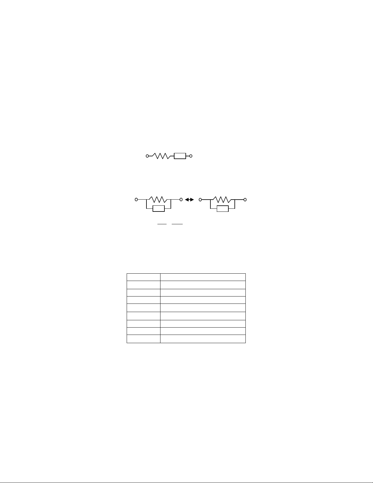
There ar e two types of the cir cuit mode. One is series mode, the
other is parallel mode. See Fi gure 1.2 t o find out t he rela tion of t he
series and parallel mode.
5
Find Quality Products Online at: sales@GlobalTestSupply.com
www.GlobalTestSupply.com
Page 8
Parameter
Range
Z
L
0.000 µH to 9999 H
C
0.000 pF to 9999 F
DCR
0.000 Ω to 9999 MΩ
ESR
D
0.000 to 9999
Q
0.000 to 9999
-180.0 ° to 180.0 °
Real and imaginary components are serial
ss
jXRZ +=
Real and imaginary components are Parallel
jB=1/jX
jBGY +=
jX
R
P
jX
1
P
R
1
Y +=
Rs jX
s
p
p
Figure 1.2
G=1/R
p
p
1.3 Specification
LCD Display Range:
0.000 Ω to 9999 MΩ
0.000 Ω to 9999 Ω
θ
6
Find Quality Products Online at: sales@GlobalTestSupply.com
www.GlobalTestSupply.com
Page 9

|Zx|
20M ~
10M ~
1M ~
100K ~
10 ~ 1
1 ~ 0.1
DCR
100Hz
120Hz
1KHz
10KHz
100KHz
NA
5%±1
2%±1
0.4% ±1
2%±1
5%±1
2
1 Dx+
Accuracy (Ae):
Z Accuracy:
Freq.
10M
(Ω)
2% ±1
5% ±1
1M
100K
(Ω)
1%
(Ω)
±
1 0.5% ±1 0.2% ±1 0.5% ±1 1% ±1
10
(Ω)
Ω
(
2% ±1
)
Ω
)
(
(886)
Note : 1.The accuracy appli es wh en th e test level is set to 1V rm s.
2.Ae multiplies 1. 25 when the test level is set to 250mVrms.
3.Ae multiplies 1.50 when the test level is set t o 50mVrms.
4.When measuring L and C, multiply Ae by
Dx
>
0.1.
: Ae is not specified if th e test level is set to 50mV.
if the
7
Find Quality Products Online at: sales@GlobalTestSupply.com
www.GlobalTestSupply.com
Page 10

C Accuracy :
79.57
pF
159.1
nF
1.591
nF
15.91
uF
159.1
uF
1591
mF
2% ± 1
1% ± 1
0.5%
1
0.2%
1
0.5%
1
1% ± 1
66.31
pF
132.6
nF
1.326
nF
13.26
uF
132.6
uF
1326
mF
2% ± 1
1% ± 1
0.5%
1
0.2%
1
0.5%
1
1% ± 1
7.957
pF
15.91
pF
159.1
nF
1.591
uF
15.91
uF
159.1
mF
2% ± 1
1% ± 1
0.5%
1
0.2%
1
0.5%
1
1% ± 1
0.795
pF
1.591
pF
15.91
pF
159.1
uF
1.591
uF
15.91
uF
5% ± 1
2% ± 1
0.5%
1
0.2%
1
0.5%
1
1% ± 1
NA
0.159
pF
1.591
pF
15.91
nF
159.1
uF
1.591
uF
NA
5% ± 1
2%± 1
0.4%
1
2%± 1
5% ± 1
100Hz
159.1
pF
|
pF
1.591
nF
|
15.91
nF
|
159.1
uF
|
1591
uF
|
|
15.91
pF
|
120Hz
1KHz
10KHz
100KHz
(886)
132.6
15.91
1.591
pF
|
pF
|
1.326
159.1
15.91
1.591
pF
|
pF
|
pF
|
pF
|
±
±
±
nF
|
pF
|
pF
|
pF
|
nF
132.6
±
nF
15.91
±
pF
1.591
±
pF
159.1
±
13.26
±
1.591
±
159.1
±
15.91
8
uF
|
1326
±
uF
|
159.1
±
uF
|
15.91
±
nF
|
1.591
uF
|
|
13.26
uF
|
|
1.591
uF
|
|
159.1
uF
|
|
15.91
Find Quality Products Online at: sales@GlobalTestSupply.com
www.GlobalTestSupply.com
Page 11

L Accuracy :
31.83
KH
15.91
H
1591
H
159.1
mH
15.91
mH
1.591
uH
2% ± 1
1% ± 1
0.5%
1
0.2%
1
0.5%
1
1% ± 1
26.52
KH
13.26
H
1326
H
132.6
mH
13.26
mH
1.326
uH
2% ± 1
1% ± 1
0.5%
± 1
0.2%
± 1
0.5%
± 1
1% ± 1
31.83
KH
1.591
H
159.1
H
15.91
mH
1.591
uH
159.1
uH
2% ± 1
1% ± 1
0.5%
± 1
0.2%
± 1
0.5%
± 1
1% ± 1
318.3
H
159.1
H
15.91
H
1.591
uH
159.1
uH
15.91
uH
5% ± 1
2% ± 1
0.5%
1
0.2%
1
0.5%
1
1% ± 1
31.83
H
15.91
H
1.591
mH
159.1
uH
15.91
uH
1.591
uH
NA
5% ± 1
2%± 1
0.4%
2%± 1
5% ± 1
KH
100Hz
120Hz
1KHz
10KHz
100KHz
(886)
15.91
KH
13.26
KH
1.591
159.1
15.91
H
H
KH
|
1591
KH
|
1326
KH
|
159.1
|
15.91
|
1.591
H
H
|
|
159.1
15.91
±
H
|
|
132.6
13.26
H
|
|
15.91
1.591
H
H
|
|
1.591
159.1
±
H
H
|
|
159.1
15.91
|
±
H
|
H
|
H
|
±
mH
|
mH
1.591
mH
1.326
mH
159.1
15.91
1.591
±
uH
±
uH
mH
|
|
159.1
mH
|
|
132.6
uH
|
|
15.91
uH
|
|
1.591
uH
|
|
0.159
9
Find Quality Products Online at: sales@GlobalTestSupply.com
www.GlobalTestSupply.com
± 1
Page 12

D Accuracy :
|Zx|
Freq.
20M ~
(Ω)
10M ~
(Ω)
1M ~
(Ω)
100K ~
(Ω)
10 ~ 1
(Ω)
1 ~ 0.1
(Ω)
0.020
0.010
0.005 ±0.002 ±0.005 ±0.010
0.050
0.020
100KHz
(886)
NA ±0.050
0.020 ±0.004 ±0.020 ±0.050
|Zx|
Freq.
20M ~
(Ω)
10M ~
(Ω)
1M ~
(Ω)
100K ~
(Ω)
10 ~ 1
(Ω)
1 ~ 0.1
(Ω)
1.046
0.523
0.261 ±0.105 ±0.261 ±0.523
2.615
1.046
100KHz
(886)
NA ±2.615
1.046 ±0.209 ±1.046 ±2.615
100Hz
120Hz
1KHz
10KHz
10M
±
±
1M
100K
±
±
±
±
10
θ Accuracy :
100Hz
120Hz
1KHz
10KHz
10M
±
±
1M
100K
±
±
±
±
10
10
Find Quality Products Online at: sales@GlobalTestSupply.com
www.GlobalTestSupply.com
Page 13

Z Accuracy:
CxfZx⋅⋅⋅
=
π
2
1
2
1 Dx+
Ω=
⋅⋅⋅⋅
=
⋅⋅⋅
=
−
1590
10100102
1
2
1
93
π
π
Cxf
Zx
As shown in table 1.
C Accuracy:
= Ae of |Zx|
C
Ae
f : Test Frequency (Hz)
Cx : Measured Capacitance Value (F)
|Zx| : Measured Impedance Value (
Accuracy applies when Dx (measured D value)
Ω
)
≦
0.1
When Dx > 0.1, multiply C
Ae
by
Example:
Tes t Condition:
Frequency : 1KHz
Level : 1Vrms
Speed : Slow
DUT : 100nF
Then
Refer to the accuracy table, get C
11
=±0.2%
Ae
Find Quality Products Online at: sales@GlobalTestSupply.com
www.GlobalTestSupply.com
Page 14

L Accuracy:
LxfZx ⋅⋅⋅=
π
2
2
1 Dx+
100
Ae
XxESR
Ae
⋅±=
Cxf
LxfXx
⋅⋅⋅
=⋅⋅⋅=
π
π
2
1
2
= Ae of |Zx|
L
Ae
f : Test Frequency (Hz)
Lx : Measured Inductance Value (H)
|Zx| : Measured Impedance V alue (
Accuracy applies when Dx (measured D value)
Ω
)
≦
0.1
When Dx > 0.1, multiply L
Ae
by
Example:
Tes t Condition:
Frequency : 1KHz
Level : 1Vrms
Speed : Slow
DUT : 1mH
Then
2
π
⋅⋅⋅=
π
LxfZx
−
33
Ω=⋅⋅⋅=
283.610102
Refer to the accuracy table, get L
=±0.5%
Ae
ESR Accuracy :
12
Find Quality Products Online at: sales@GlobalTestSupply.com
www.GlobalTestSupply.com
Page 15

ESRAe = Ae of |Zx|
Ω=
⋅⋅⋅⋅
=
⋅⋅⋅
=
−
1590
10100102
1
2
1
93
π
π
Cxf
Zx
Ω±=⋅±= 18.3
100
Ae
XxESR
Ae
100
Ae
D
Ae
±=
f : Test Frequency (Hz)
Ω
Xx : Measured Reactance Value (
)
Lx : Measured Inductance Value (H)
Cx : Measured Capacitance Value (F)
Accuracy applies when Dx (measured D value)
Example:
Tes t Condition:
Frequency : 1KHz
Level : 1Vrms
Speed : Slow
DUT : 100nF
Then
≦
0.1
Refer to the accuracy table, get
=±0.2%,
C
Ae
D Accuracy:
13
Find Quality Products Online at: sales@GlobalTestSupply.com
www.GlobalTestSupply.com
Page 16

DAe = Ae of |Zx|
Ω=
⋅⋅⋅⋅
=
⋅⋅⋅
=
−
1590
10100102
1
2
1
93
π
π
Cxf
Zx
002.0
100
±=⋅±=
Ae
D
Ae
DeQx
DeQx
Ae
Q
⋅
⋅
±=
1
2
Accuracy applies when Dx (measured D value)
When Dx > 0.1, multiply Dx by (1+Dx)
Example:
Tes t Condition:
Frequency : 1KHz
Level : 1Vrms
Speed : Slow
DUT : 100nF
Then
≦
0.1
Refer to the accuracy table, get
=±0.2%,
C
Ae
Q Accuracy:
Q
= Ae of |Zx|
Ae
Qx : Measured Quality Factor Value
De : Relative D Accuracy
14
Find Quality Products Online at: sales@GlobalTestSupply.com
www.GlobalTestSupply.com
Page 17

Accuracy applies when
1<⋅ DeQx
005.0
100
±=⋅±=
Ae
De
1.01
θ
100
Ae
π
180
e ⋅=θ
Example:
Tes t Condition:
Frequency : 1KHz
Level : 1Vrms
Speed : Slow
DUT : 1mH
Then
π
LxfZx
2
π
⋅⋅⋅=
33
−
Ω=⋅⋅⋅=
283.610102
Refer to the accuracy table, get
=±0.5%,
L
Ae
If measur ed Qx = 20
Then
2
⋅
1
±=⋅
DeQx
DeQx
±=
Q
Ae
2
Accuracy:
15
Find Quality Products Online at: sales@GlobalTestSupply.com
www.GlobalTestSupply.com
Page 18

Example:
Ω=
⋅⋅⋅⋅
=
⋅⋅⋅
=
−
1590
10100102
1
2
1
93
π
π
Cxf
Zx
deg115.0
100
2.0180
100
Ae180
Ae
±=⋅
π
±=
⋅
π
±=θ
Tes t Condition:
Frequency : 1KHz
Level : 1Vrms
Speed : Slow
DUT : 100nF
Then
Refer to the accuracy table, get
=±0.2%,
Z
Ae
Tes ting Signal:
Level Accuracy : ± 5%
Frequency Accuracy : 0.1%
Output Impedance : 100Ω ± 5%
Measuring Speed:
Fast : 4.5 meas. / sec.
Slow : 2.5 meas. / sec.
16
Find Quality Products Online at: sales@GlobalTestSupply.com
www.GlobalTestSupply.com
Page 19

General:
°
Temperature : 0
-20
Relative Humidity : Up to 85%
Battery Type : 2 AA size Ni-Mh or Alkaline
Battery Charge : Constant c urr ent 150mA
Battery Operatin g Time : 2.5 Hours typical
AC Operation : 110/220V A C, 60/50Hz with proper
Low Power Warning : under 2.2V
Dimensions : 174mm x 86mm x 48mm (L x W x H)
Weight : 470g
Considerations
Tes t Frequency. The test frequency is user selectable and can be
changed. G ene rally, a 1 KHz test signal or higher is used to measure
capacitors that are 0.01uF or smaller and a 120Hz test signal is used
for capacitors that are 10uF or larger. T ypically a 1 kHz test signal or
higher is used to measure induc tors that are used in audio and RF
(radio frequency) circuits. This is because these components operate
at higher frequencies and require that they be measure d at a hi gher
frequency of 1 KHz. Generally, inductors below 2mH should be
measured at 1 kHz and inductors above 200H should be measured at
120Hz.
It is best to check with the componen t manufacturers’ data sheet to
determine the best test fre quency for the device.
C to 70°C (Operating)
°
C to 70°C (Storage)
approximately
adapter
6.9” x 3.4” x 1.9”
17
Find Quality Products Online at: sales@GlobalTestSupply.com
www.GlobalTestSupply.com
Page 20

Charged Capacitors
Always discharge any capacitor prior to making a
measurement since a charged ca pacitor may serious ly damage
the meter.
Effect Of High D on Accuracy
A low D (Dissipation Factor) reading is desirable. Electrolytic
capacitor s i nherently have a higher dissipation factor due to their
normally high internal leakage characteristics. If the D (Dissipation
Factor) is ex c es sive, the capacitance measurement accuracy may be
degraded.
It is best to check with the componen t manufacturers’ data sheet to
determine the desirabl e D val ue of a good component.
Measuring Capacitance of Cables, Switches or Other Parts
Measuring the capacitance of coaxial cables is very useful in
determining the actual length of the cable. Most manufacturer
specifications list the amount of capacitance per foot of cable and
therefore the length of the cable can be determined by measuring the
capacitance of that cable.
For examp le: A manufa cturers , specificat ion calls out a certa in cable,
to have a capa citance of 10 pF per foot, After measuring the cable a
capacitance reading of 1.000 nF is displayed. Dividing 1000pF
(1.000 nF) by 10 pF per foot yields the length of the cable to be
approximately 100 feet.
18
Find Quality Products Online at: sales@GlobalTestSupply.com
www.GlobalTestSupply.com
Page 21

Even if the manufacturers’ specification is not known, the
capacitance of a measured length of cable (such as 10 feet) can be
used to determine the capacitance per foot; do not use too short a
length such as one foot, because any error becomes magnified in the
total leng th calculations.
Sometimes , the cap aci tan ce of switches, inter co n n ect cables, circuit
board foils, or other parts, affecting stray capacitance can be critical
to circuit design, or must be repeatable from one unit to another.
Series Vs P a ra llel Measu rem en t (for Inductors)
The seri es mode dis plays the more accurate me asurement in most
cases. The series equivalent mode is essential for obtaining an
accurate Q reading of l ow Q inductors. Where ohmic losses are
most significant, the series equivalent mode is preferred. However,
there are cases where the parallel equivalent mode may be more
appropriate. For iron core induct or s operating at higher fre quenci es
where hysteresis and eddy currents become significant,
measurement in the parallel equivalent mode is preferred.
1.4 Accessories
Operating Manual 1 pc
2 AA Size Ni-Mh Rechargeable Batteries 2 pc
Shorting Bar 1 pc
AC to DC Adapter 1 pc
TL885A SMD Test Probe 1 pc
TL885B 4-Wire Test Clip (Optional)
TL08C Kelvin Clip (Optiona l)
19
Find Quality Products Online at: sales@GlobalTestSupply.com
www.GlobalTestSupply.com
Page 22

Carrying Case (Optional)
20
Find Quality Products Online at: sales@GlobalTestSupply.com
www.GlobalTestSupply.com
Page 23

2. Operation
1. NA
2. Primary Parameter Display
5. Model Number
6. Power Switch
7. Relative Key
8. Measurement Level Key
9. Open/Short Calibration Key
10. Measurement Frequency Key
13. Range Hold Key
14. L/C/Z/DCR Function Key
15. Battery Cha rge Indicator
16. DC Adapter Input Jack
17. Guard Terminal
18. HPOT/HCUR Terminal
19. LPOT/LCUR Terminal
20. Battery Compartment
2.1 Physical Description
G
H
POT
CUR
UARD
L
POT
LH
CUR
G
UARD
3. Secondary Parameter Display 4. Low Battery Indicator
12. D/Q/
θ
11. Display Update Speed Key
/ESR Function Key
21
Find Quality Products Online at: sales@GlobalTestSupply.com
www.GlobalTestSupply.com
Page 24

2.2 Making Measurement
1
Screws
Battery Compartment
4
Norm/Ni-Mh Switch
5
Back Case
6
Tilt Stand
2.2.1 Battery Replacement When the LOW BATTERY INDICATOR lights up duri ng normal
operation, the batteries in the Models 885 & 886 should be replaced
or recharged to maintain proper operation. Please perform the
following steps to change the batteries:
1. Remove the battery hatch by unscrewing the screw of the
battery compartment.
2. Take out the old batteries and insert the new batteries int o the
battery compartment. Please watch out for battery polarity
when installing new batteries.
3. Replace the battery hatch by rever sing the procedure used t o
remove it.
2
Hatch
3 Batteries
Battery Replacement
22
Find Quality Products Online at: sales@GlobalTestSupply.com
www.GlobalTestSupply.com
Page 25

23
2.2.2 Battery Recharging/AC operation
!
rechargeable batteries.
Caution
Only the Models 885 or 886 st andar d acces sory AC t o DC
adapter can be used with Model 885. Other battery elimina tor
or charger may result in damage to Modes 885 or 886.
The Models 885 & 886 works on external AC power or internal
batteries. To power the Mode l 885 wi th A C source, make s ure t hat
the Models 885 or 886 is off, then plug one end of the AC to DC
adapter into the DC jack on the right si de of the instr ument and the
other end into an AC outlet.
There is a small slide switch inside the battery compartment
called Battery Select Switch. If the Ni-Mh or Ni-Cd rechargeable
batteries are installed in Models 885 or 886, set the Batter y Select
Switch to "Ni -Mh" posi tion. The Ni-Mh or Ni-Cd batteries ca n be
recharged when the instrument i s oper at ed by AC source. The LED
for indicating battery charging will light on. If the non-rechargeable
batteries (such as alkaline bat teries) are i nstalled in Models 885 or
886, set the Battery Select Switch to "NORM" position for
disconnecting the charging circuit to the batteries.
Warning
The Battery Select Switch must be set in the "NORM"
position when using nonNon-rechargeable batt erie s may e xplode if the AC a dapter is
used with non-rechargea ble batteries. Warranty is voided if
this happened.
Find Quality Products Online at: sales@GlobalTestSupply.com
www.GlobalTestSupply.com
Page 26
24
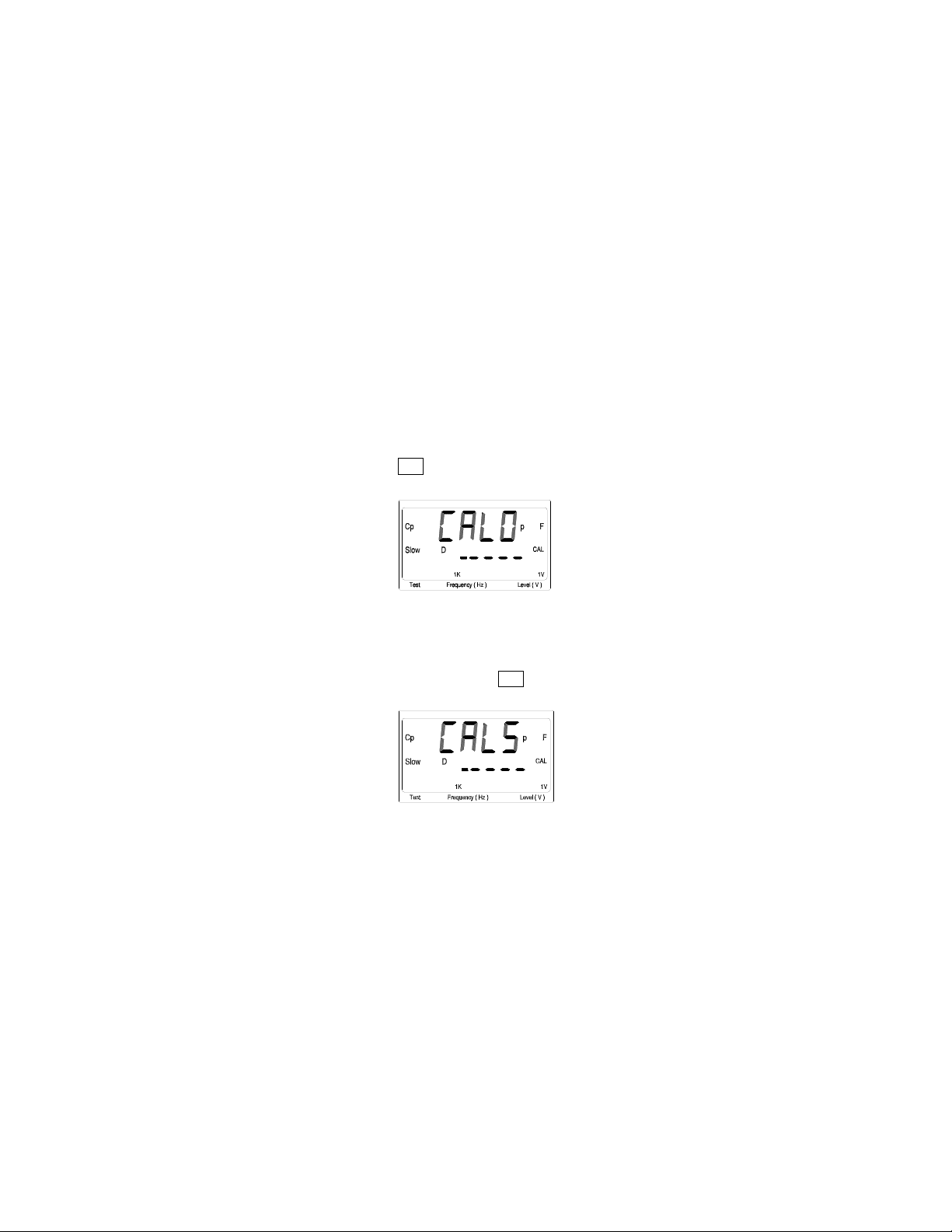
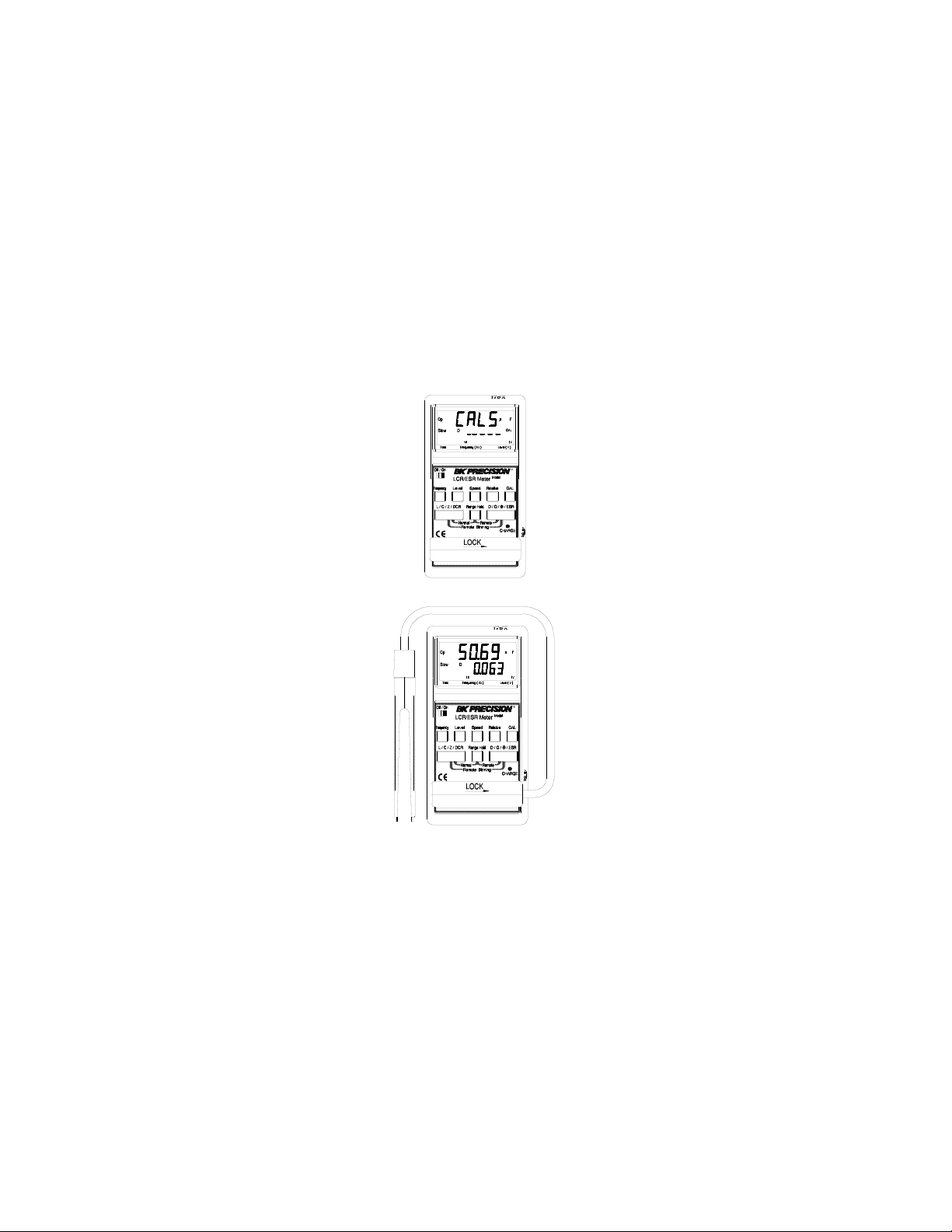
2.2.3 Open and Short Calibrati on The Models 885 & 886 provides open/short calibration
capability so the user can get better accuracy in measuring high and
low impedance. We recommend that the user performs open/shor t
calibratio n if the test level or frequency has been changed.
Open Calibration
First, remain ing the m easurem ent terminals with the open status,
then press the CAL key shor tly ( no more than t wo sec ond), t he
LCD will display:
This calibration ta kes about 10 se con ds. After it is finished, the
Model 885 will beep to show that the calibration is done.
Short Calibration
To pe rform the short calibration, insert the Shorting Bar into the
measurement terminals. Press the CAL key for more than two
second, the LCD will display:
This calibration ta kes about 10 se con ds . After it i s fi nishe d, t he
Model 885 will beep to show that the calibration is done.
Find Quality Products Online at: sales@GlobalTestSupply.com
www.GlobalTestSupply.com
Page 27
25
2.2.4 Display Speed
The Models 885 & 886 provides two different display speeds
(Fast/Slow). It is controlled by the Speed key. When the speed is set
to fast, the display will update 4.5 readings every second. When the
speed is set to slow, it’s only 2.5 readings per second.
2.2.5 Relative Mod e
The relative mode lets t he user to make quick sort of a bunch of
components. First, insert the standard value compone nt to get the
standard value reading. (A pproximate ly 5 seconds in Fast Mode to
get a stable reading.) Then, press the Relative key, the primary
display will reset to zero. Remove the standard value component
and insert the unknown component, the LCD will show the value
that is the difference between the standard value and unknown
value.
2.2.6 Range Hold
To set the range hold, insert a standard component in that
measurement range. (A pproximately 5 seconds in Fast Mode to get
a stable reading.) Then, by pressing the Range Hold key it will hold
the range within 0.5 to 2 times of the curr ent measurement range.
When the Range Hold is pr ess the LCD display:
Find Quality Products Online at: sales@GlobalTestSupply.com
www.GlobalTestSupply.com
Page 28

26
2.2.7 DC Resistance Measurement
The DC resistance measurement measures the resistance of an
unknown component by 1VDC. Select the L/C/Z/DCR key to make
the DCR measurement. The LCD display:
2.2.8
AC Impedan ce Mea s u r em ent
The AC impedance measurement measures the Z of an unknow n
device. Sele ct th e L/C/Z/DCR key to m ake th e Z m e asur emen t. T h e
LCD display:
The testing level and fre quency can by selected by pressing the
Level key and Frequency key, respectively.
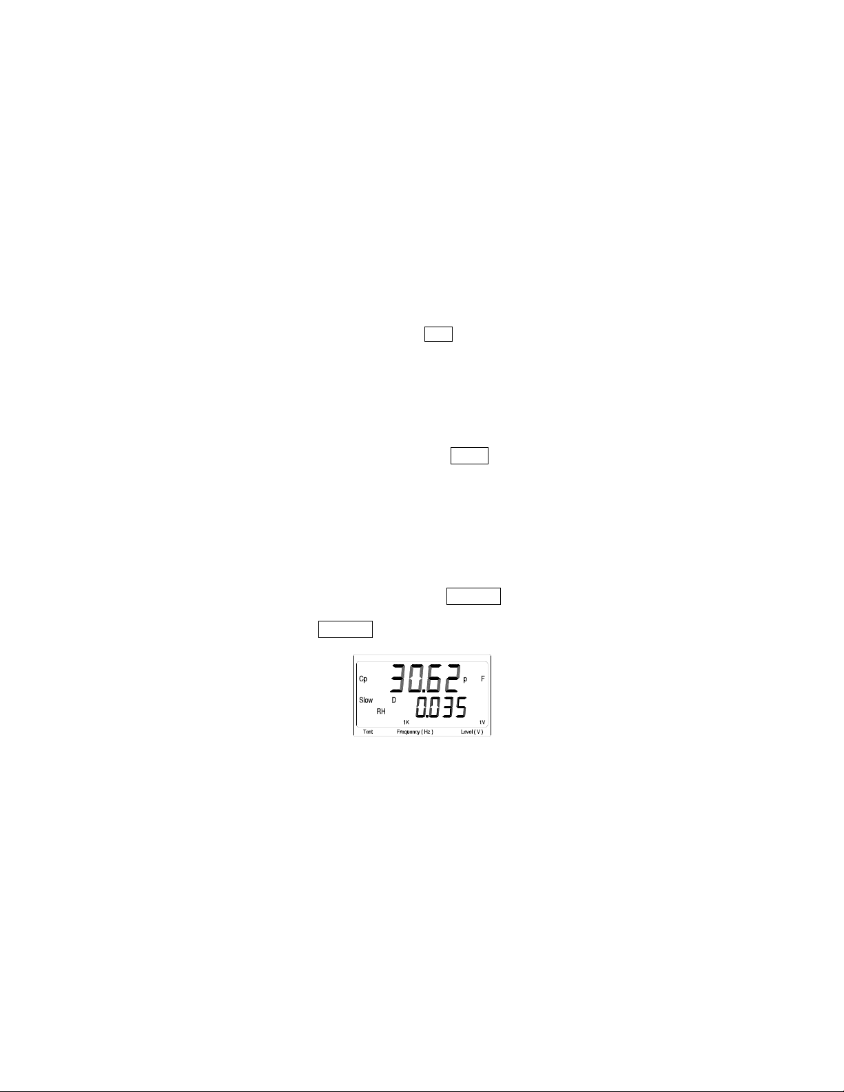
2.2.9 Capacitance Measurement
To measure the capacitance o f a com ponent, select the L/C/Z/DCR
key to Cs or Cp mode. Due to the circuit structure, t here are two
modes can by selected (Serial Mode – Cs and Parall el Mode – Cp).
If the serial mode (Cs) is selected, the D, Q and ESR can be shown
on the secondary display. If the parallel mode (Cp) is selected, only
the D and Q can be shown on the secondary display. The following
Find Quality Products Online at: sales@GlobalTestSupply.com
www.GlobalTestSupply.com
Page 29
27
shows some examples of capacitance measurement:
The testing level and fre quency can by selected by pressing the
Level key and Frequency key, respectively.
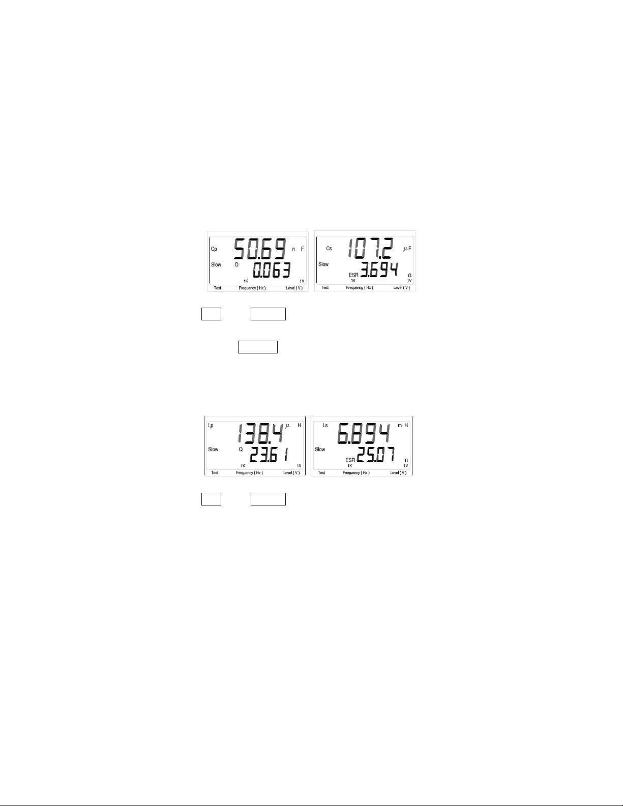
2.2.10 Inductance Measurement
Select the L/C/Z/DCR key to Ls or Lp mode for measuring the
inductance in serial mode or parallel mode. If the serial mode (Ls) is
selected, the D, Q and ESR can be shown on the seconda ry display.
If the parallel mode (Lp) is selected, only the D and Q can be shown
on the secondary display. The following shows some examples of
capacitance measurement:
The testing level and fre quency can by selected by pressing the
Level key and Frequency key, respectively.
Find Quality Products Online at: sales@GlobalTestSupply.com
www.GlobalTestSupply.com
Page 30
28
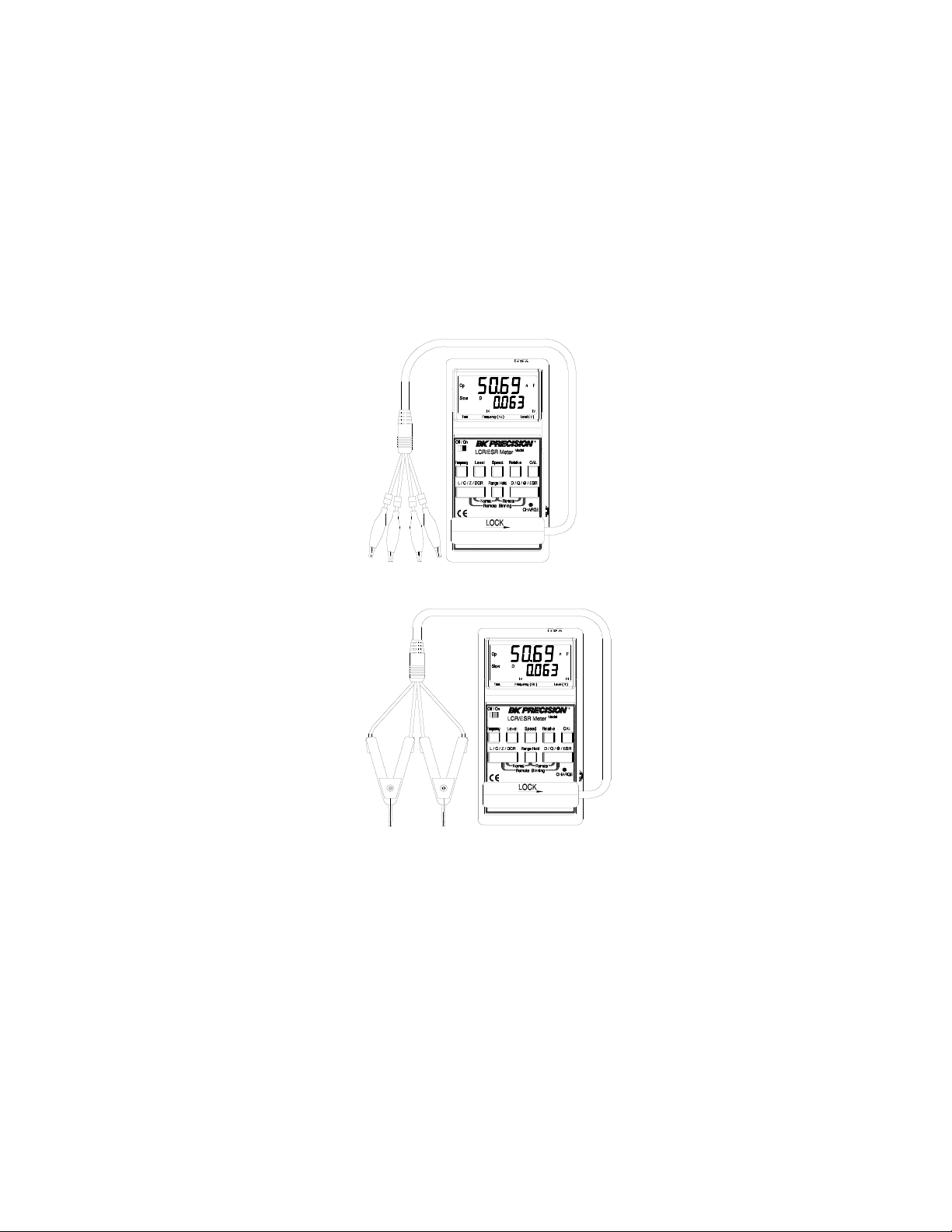
2.3 Accessory Operation
Follow the figures below to attach the test probes for making
measurement.
Shorting Bar
TL885A SMD Test Probe
Find Quality Products Online at: sales@GlobalTestSupply.com
www.GlobalTestSupply.com
Page 31
29
H
H
P
C
C
L
L
P
TL885B 4-Wire Test Clip
TL08C Kelvin Clip
Find Quality Products Online at: sales@GlobalTestSupply.com
www.GlobalTestSupply.com
Page 32

30
4. Application
R
H
CUR
H
POT
DUT
(b) BLOCK DIAGRAM
DUT
V
A
Co
o
L
o
RoL
o
(a) CONNECTION
(c) TYPICAL IMPEDANCE MEASUREM ENT RANGE(£[)
2T
1m 10m 100m 1 10 1K 10K 100K1M100 10M
L
POT
L
CUR
4.1 Test Leads Connection
Auto balancing bridge has four terminals (H
) to connect to the device under test (DUT). It i s important to
L
POT
CUR
, H
POT
, L
CUR
and
understand what connection method will affect the measurement
accuracy.
2-T e rminal (2T)
2-T erminal is the easiest way to connect the DUT , but it contents
many errors which are the inductor and resi stor as well as the
parasitic capacitor of the test leads (Figure 3.1). Due to these
errors in measurement, the effective impedance measurement
Ω
range will be limited at 100
to 10KΩ.
Figure 3.1
3-T e rminal (3T)
Find Quality Products Online at: sales@GlobalTestSupply.com
www.GlobalTestSupply.com
Page 33

31
3-Terminal uses coaxial cable to reduce the effect of the
DUT
V
A
(d) 2T CONNECTION WITH SHILDING
H
CUR
H
POT
DUT
(b) BLOCK DIAGRAM
DUT
V
A
Co
Ro
Lo
Ro L
o
Co doesn't
effect
measurement
result
(a) CONNECTION
(c) TYPICAL IMPEDANCE MEASUREMENT RANGE(£[)
3T
1m 10m 100m 1 10 1K 10K 100K 1M100 10M
L
POT
L
CUR
parasitic capacitor (Figure 3.2). The shield of the coaxi al cable
should connect to guard of the instrument to increase the
Ω
measurement range up to 10M
.
Figure 3.2
4-T e rminal (4T)
4-Terminal connection reduces the effect of the test lead
Find Quality Products Online at: sales@GlobalTestSupply.com
www.GlobalTestSupply.com
Page 34

32
resistance (Figure 3.3). This connection can improve the
H
CUR
H
POT
DUT
(b) BLOCK DIAGRAM
DUT
V
A
(a) CONNECTION
(c) TYPICAL IMPEDANCE MEASUREM ENT RANGE (£[)
4T
1m 10m 100m 1 10 1K 10K 100K1M100 10M
L
POT
L
CUR
Ω
measurement range down t o 10m
. However, the effect of the
test lead inductance can’t be eliminated.
Figure 3.3
5-T e rminal (5T)
5-Ter mi nal connection is the c ombi nation of 3T and 4T (Figure
3.4). It has four coaxial cables. Due to the advanta ge of the 3T
and 4T, this connection can widely increase the measurement
Ω
range for 10m
to 10MΩ.
Find Quality Products Online at: sales@GlobalTestSupply.com
www.GlobalTestSupply.com
Page 35

33
(d) WRONG 4T CONNECTION
H
POT
DUT
(b) BLOCK DIAGRAM
(a) CONNECTION
(c) TYPICAL IMPEDANCE MEASUREM ENT RANGE (£[)
5T
1m 10m 100m 1 10 1K 10K 100K1M100 10M
H
CUR
DUT
V
A
DUT
V
A
L
POT
L
CUR
Figure 3.4
4-T e rminal Path (4TP)
4-Ter minal Path connection solves the proble m that caused by
the test lead inductance. 4TP uses four coaxial cables to isolate
the current path and the vol tage sense cable (Figure 3.5). The
return current will flow through t he coaxial ca ble as well as the
shield. Theref ore, the magnetic flux that generated by int ernal
conductor will cancel out the magnetic flux generated by
external conductor ( shield). The 4TP connection increase s the
Find Quality Products Online at: sales@GlobalTestSupply.com
www.GlobalTestSupply.com
Page 36

34
measuremen t range from 1mΩ to 10MΩ.
(b) BLOCK DIAGRAM
(a) CONNECTION
DUT
V
A
(c) TYPICAL IMPEDANCE
MEASUREMENT RANGE(£[)
4T
1m 10m100m 1 10 1K 10K 100K1M100 10M
H
POT
DUT
H
CUR
L
CUR
L
POT
H
POT
DUT
H
CUR
L
CUR
L
POT
(d) 4T CONNECTION W ITH SHILDING
Figure 3.5
Eliminating the Effect of the Parasitic Capacitor
When measuring the high impedance component (i.e. low
capacitor), the par asitic capacitor becomes an important issue
(Figure 3.6). In figure 3.6(a), the parasitic capacitor Cd is
paralleled to DUT as well as the Ci and Ch. To correct this
problem, add a guard pla ne (F igure 3.6(b)) in be twee n H and L
terminals to break the Cd. If the guard plane is connected to
instrument guard, t he effect of Ci a nd Ch will be removed.
Find Quality Products Online at: sales@GlobalTestSupply.com
www.GlobalTestSupply.com
Page 37

35
HCUR HPOT LPOT LCUR
HCUR HPOT LPOT LCUR
Cd
DUT
Ch Cl
(a) Parastic Effect
Guard
Plant
Connection
Point
Ground
(b) Guard Plant reduces
Parastic Effect
Figure 3.6
4.2 Open/Short Compensation
For those precision impeda nce mea suri ng instr ument, the ope n and
short compensation nee d to be used to reduce the parasit ic effect of
the test fixture. The parasitic effect of the test fixture can be treated
like the simple passive components in figure 3.7(a). When the DUT
ω
is open, the instrument gets the conductance Yp = Gp + j
Cp
(Figure 3.7(b)). When the DUT is short, the instrument gets the
ω
impedance Z s = Rs + j
Ls (Figure 3.7(c)). After the open and short
compensation, Yp and Zs are for calculating the real Zdut ( Figure
3.7(d)).
Find Quality Products Online at: sales@GlobalTestSupply.com
www.GlobalTestSupply.com
Page 38

36
H
CUR
H
POT
L
CUR
L
POT
Zdut
C
o
RsL
s
G
o
Z
m
Redundant
Impedance
(Z
s
)
Parastic
Conductance
(Y
o
)
Parastic of the Test Fixture
(a) Parastic Effect of the Test Fixture
H
CUR
H
POT
L
CUR
L
POT
C
o
R
s
L
s
G
o
(b) OPEN Measurement
Y
o
OPEN
Y
o
= Go + j£sC
o
1
(R
s
+ j£s<< )
G
o
+j£sC
o
H
CUR
H
POT
L
CUR
L
POT
C
o
R
s
L
s
G
o
(c) SHORT Measurement
Z
s
SHORT
Z
s
= Rs + j£sL
s
Figure 3.7
Find Quality Products Online at: sales@GlobalTestSupply.com
www.GlobalTestSupply.com
Page 39

37
Zs
Zm
Yo Zdut
(d) Compensation Equation
Zm - Zs
Zdut =
1-(Z
m-Zs)Yo
Figure 3.7 (Continued)
4.3 Selecting t h e Series or Paral lel Mode
According to different measuring requirement, there are ser ie s
and parallel modes to describe the measurement result. It is
depending on the hi gh or low i mpeda nce va lue t o deci de what
mode to be used.
Capacitor
The impedance and capacitance in the capacitor are negatively
proportional. Therefore, the large capacitor means the low
impedance; the small capacitor means the high impedance.
Figure 3.8 shows the equivalent circuit of capacitor. If the
capacitor is small, the Rp is more i mportant than the Rs. If the
capacitor is large, the Rs shouldn’t be avoided. Hence, uses
parallel mode to measure low capacitor and series mode to
measure high capacitor.
Find Quality Products Online at: sales@GlobalTestSupply.com
www.GlobalTestSupply.com
Page 40

38
R
C
R
Effect
No Effect
Large capacitor
R
P
C
R
Effect
Figure 3.8
Small capacitor
(High impedance)
(Low impedance)
P
S
Inductor
No Effect
S
The impedance and inductive in the inductor are positively
proportional. Therefore, the large inductor equals to the high
impedance and vice versa. Figure 3.9 shows the equivalent
circuit of inductor. If the inductor is small, the Rs is more
important than the Rp. I f the inductor is large, the Rp shoul d be
taking care of. So, uses series mode to measure low inductor and
parallel mode to measure hi gh inductor.
Find Quality Products Online at: sales@GlobalTestSupply.com
www.GlobalTestSupply.com
Page 41

39
R
P
L
R
(High impedance)
No Effect
R
P
L
R
Large inductor
Effect
S
Small inductor
(Low impedance)
No Effect
S
Effect
Figure 3.9
Find Quality Products Online at: sales@GlobalTestSupply.com
www.GlobalTestSupply.com
Page 42

40
5. Limited Three-Year Warranty
B&K Precision Corp. warrants to the original
purchaser that its products and the component parts
thereof, will be free from defects in workmanship and
materials for a period of three years
purchase.
B&K Precision Corp. will, without c harge, repair or
replace, at its option, defective product or component
parts. Returned product must be accompanied by
proof of the purchase date in the form of a sales
receipt.
lusions: This warranty does not apply in the event of misuse or
Exc
abuse of the product or as a result of unauthor ized alternations or
repairs. It is void if the serial number is alternated, defaced or
removed.
B&K Precision Corp. shall not be liable for any consequential
damages, including wit hout limitati on damages resul ting from loss
of use. Some states do not allow limitation of incidental or
consequential da mages, so the above limitation or exclusion may
not apply to you.
This warranty gives you specific rights and you may have other
rights, which vary from state-to-state.
from date of
Find Quality Products Online at: sales@GlobalTestSupply.com
www.GlobalTestSupply.com
 Loading...