

Page 1
INSTRUCTION MANUAL
MANUAL DE INSTRUCCIÓNES
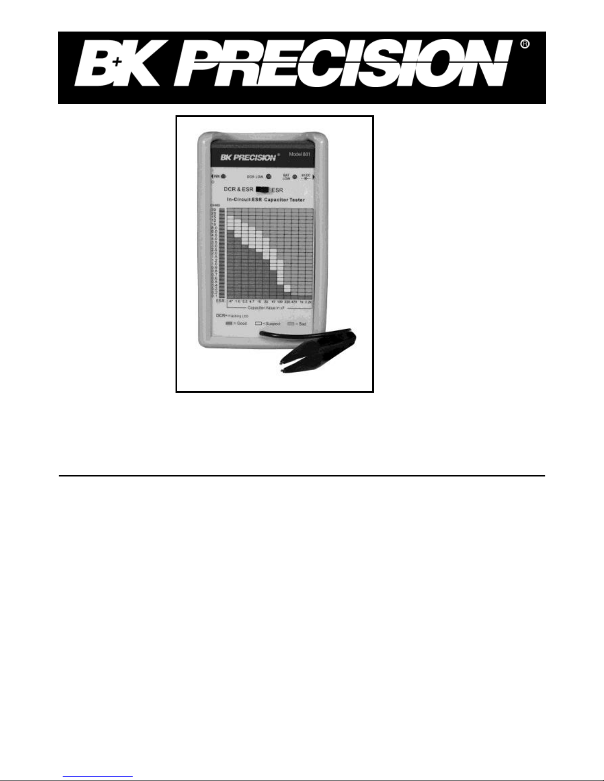
In-Circuit ESR & DCR Cap Tester
Model 881
MEDIDOR DE RESISTENCIA ESR&DSR DE
CAPACITORES
MODELO 881
Page 2

2
SAFETY GUIDELINES
WARNING
An electrical current of over 10 milliamps passing through the heart
will stop most human hearts. Voltage of as low as 35 Volts dc or ac
rms should be considered hazardous since it can produce lethal
current under certain conditions. Be sure to observe the following
safety precautions:
1. There are no high voltages in the Cap Tester, but the equipment
under test usually contains hazardous high voltage. Always follow
the safety recommendations of the manufacturer of your
equipment.
2. Some equipment may be wired as a "hot chassis" type; equipment
using two-wire power plugs are always suspect and it may even
include those with polarized plugs. Never touch chassis of "hot
chassis" type equipment to avoid the possibility of a serious,
possibly fatal electrical shock.
3. Don't expose yourself needlessly to high voltage; only remove
housings and covers when necessary.
4. Familiarize yourself with the equipment being tested and the
location of its high voltage points. However be aware that high
voltage may appear at unexpected points in defective equipment.
5. Never work alone. Someone should be nearby to render aid if
needed. Training in CPR (Cardio-pulmonary resuscitation) is
highly recommended.
Page 3

3
SPECIFICATIONS
Specifications
Open circuit probe voltage 15mV pp (typical)
Output test frequency 100 KHz sine wave (typical)
Measures ESR
ESR range ohms 0.1 – 30
(25 segment LED bar scale) Beeps from 1 to 5 beeps depending on
ESR of capacitor
Measures DCR
DCR range ohms 0.5 - 30 flashing
the LED
Power One 9V battery or
an external AC
adapter (9V DC
150mA 5.5mm x
2.1 mm center
pin+)
Power drain 10mA typical
Dimensions 2.1" x 3.6" x 6.0"
NOTE: Specifications and information are subject to change without
notice. Please visit www.bkprecision.com for the most current product
information.
Page 4

4
CONTROLS AND INDICATORS
1. Power Switch - Power on or off
2. DCR Low Indicator - LED turns on when DCR low
3. Mode switch - Selects test modes "ESR" or
"DCR&ESR"
4. ESR or DCR Indicator - Indicate the ESR or DCR
5. Colored chart - The three-colored chart that show typical ESR
readings of good, fair, and bad capacitors depending
on their capacitance.
6. Square connector - Capacitance
7. Bat Low - Indicates battery condition.
8. AC Adapter Jack - 9V DC, 100mA center pin + adapter
input.
8 7
Page 5

5
In-Circuit ESR & DCR Capacitor Tester
MODEL 881
8
7
6
Page 6

6
INTRODUCTION:
The In-circuit ESR & DCR capacitor tester is specially designed to
measure ESR (equivalent Series Resistance) on capacitors in the range of
0.47uf and up, in or out of circuit. The output test frequency of the meter
is a 100KHz SINE WAVE. The output voltage is 15mV pp and will not
turn on any solid state devices in the circuit under test.
It includes a one-handed tweezers test probe, microprocessor controlled,
automatically discharges the capacitors under test, checks for low DCR,
checks and displays ESR on a 25 segment LED bar scale, and beeps from
one to five beeps depending on the ESR reading of the capacitor. It has a
three-colored chart on the front panel that show typical ESR readings of
good, fair, and bad capacitors depending on their capacitance.
OPERATION:
1. Place the mode switch to the position for measurement.
2. Turn the unit on and wait for it to beep once to indicate it is ready.
3. Hold the tweezers’ test probe cross the capacitor leads to measure
ESR of the capacitor
4. Read the ESR of the capacitor according to the LED bar scale and
three-colored chart.
APPLICATIONS:
Using the tester to measure electrolytic capacitors in or out of circuit,
When the meter is turned on, it will automatically calibrate the internal circuit,
and then it will beep once to indicate it's ready. (Note: Before the unit beeps to
signal it is ready, don't have the tweezers’ test probes shorted together or
connected to a capacitor, otherwise the meter will continue to sound an alarm
until the test probe is opened or the capacitor is removed.)
The meter has two modes for performing in-circuit ESR measurements ("DCR
& ESR" mode and "ESR" mode). Place the mode switch to the position for
measurement.
Page 7

7
To measure the ESR on a capacitor, hold the tweezers’ test probe cross the
capacitor leads. The meter's probes are nonpolar.
On the "ESR" mode, the meter performs a set cycle of tests each time it is
connected to a capacitor. First it discharges the capacitor, then it measures the
ESR and indicates the range of the value with the 25 LED bar, and also sounds
one or more times depending on the ESR of the capacitor (see table 1). The
three-color chart on the panel shows typical electrolytic capacitors ESR readings.
If the capacitor's ESR range is in the green areas, it is good, and if the capacitor's
ESR range is in the red areas, it must be replaced. If the capacitor's ESR range is
in the yellow areas it's questionable and is up to the technician to decide on
whether to replace this capacitor, or not. The capacitor with higher voltage
ratings and used in circuits not requiring particularly low ESR may still work
adequately in the yellow area. However, the modem solid circuits such as switch
power supplies require low ESR capacitor. The ESR of a good capacitor depends
upon the type of material, value and voltage rating.
On the "ESR" mode, the meter will indicate that a shorted capacitor is good
because the meter does not perform the DCR measurement. Therefore, only in
the "OCR & ESR mode" will the meter detect shorted capacitor in its DCR cycle.
Table 1
On the "DCR & ESR" mode, first it discharges the capacitor, then it checks the
DC resistance and if the DC resistance is less than 30 ohm, it will stop on the
DCR cycle, otherwise, it measures the ESR and indicates the range of the value
with the 25 LED bar. On this mode, the meter detects shorted capacitor in its
Beeps from 1 to 5 beeps depending on ESR
ESR range ohms: 0 - 0.552
0.5 -152
1 -. 352
3 - 852
8-3052
One sound
Two sounds
Three sounds
Four sounds
Five sounds
Beeps from 1 to 5 beeps depending on ESR
SR range ohms: 0 - 0.552 One sound
0.5 -152 Two sounds
1 -. 352 Three sounds
3 - 852 Four sounds
8 - 3 0 5 2 Five sounds
Page 8

8
DCR cycle.
If the meter stops on the DCR cycle, it first sounds an alarm and turns on the
DCR LOW led, then indicates DC resistance by flashing the LED on the LED
bar and also sounds one or more times depending on the DC resistance (see table
2).
Table 2
The meter automatically discharges capacitors before testing. However, if
capacitors are large enough, and there is enough voltage stored, it may damage
the test probe. We recommend that for a large capacitor, you should discharge it
before you
test it.
You can use the "ESR" mode to test a capacitor with a parallel inductor if the
inductor has a large inductance at 100 kHz test frequency and have no affect on
the ESR reading. For example, there are motor, switch power supply transformer
and TV yoke windings etc.
On the "ESR" mode, the meter is an AC ohm meter, it can be used to measure
low value non-inductive resistors. It also may be used to measure small inductors
and compare meter reading to the known good inductors.
Measures DCR by flashing the LED on the LED bar
DCR range ohms: 0 - 0.5Ω flashing the 0.5ΩLED
0.5- 1.2Ω flashing the 1.2Ω LED
1.2 - 2.5Ω flashing the 2.5Ω LED
2.5 - 4.5Ω flashing the 4.5Ω LED
4.5 - 10Ω flashing the 10ΩLED
10 - 20Ω flashing the 20Ω LED
20- 30Ω flashing the 30Ω LED
Beeps from 1 to 3 beeps depending on DCR
DCR range ohms: 0 - 1.252 One sound
1.2 - 4.552 Two sounds
4.5 - 3 052 Three sounds
Beeps from 1 to 5 beeps depending on ESR
ESR range ohms: 0 - 0.552
0.5 -152
1 -. 352
3 - 852
8-3052
One sound
Two sounds
Three sounds
Four sounds
Five sounds
Page 9

9
Limited One-Year Warranty
B&K Precision Corp. warrants to the original purchaser that its products
and the component parts thereof, will be free from defects in
workmanship and materials for a period of one year from date of
purchase.
B&K Precision Corp. will, without charge, repair or replace, at its
option, defective product or component parts. Returned product must be
accompanied by proof of the purchase date in the form of a sales
receipt.
To obtain warranty coverage in the U.S.A., this product must be
registered by completing a warranty registration form on
www.bkprecision.com within fifteen (15) days of purchase.
Exclusions: This warranty does not apply in the event of misuse or
abuse of the product or as a result of unauthorized alterations or
repairs. The warranty is void if the serial number is altered,
defaced or removed.
B&K Precision Corp. shall not be liable for any consequential damages,
including without limitation damages resulting from loss of use. Some
states do not allow limitations of incidental or consequential damages.
So the above limitation or exclusion may not apply to you.
This warranty gives you specific rights and you may have other rights,
which vary from state-to-state.
B&K Precision Corp.
22820 Savi Ranch Parkway
Yorba Linda, CA 92887
www.bkprecision.com
714-921-9095
Page 10

10
SERVICE INFORMATION
Warranty Service: Please return the product in the original packaging
with proof of purchase to the address below. Clearly state in writing the
performance problem and return any leads, probes, connectors and
accessories that you are using with the device.
Non-Warranty Service: Return the product in the original packaging
to the address below. Clearly state in writing the performance problem
and return any leads, probes, connectors and accessories that you are
using with the device. Customers not on open account must include
payment in the form of a money order or credit card. For the most
current repair charges please visit www.bkprecision.com and click on
“service/repair”.
Return all merchandise to B&K Precision Corp. with pre-paid shipping.
The flat-rate repair charge for Non-Warranty Service does not include
return shipping. Return shipping to locations in North American is
included for Warranty Service. For overnight shipments and non-North
American shipping fees please contact B&K Precision Corp.
B&K Precision Corp.
22820 Savi Ranch Parkway
Yorba Linda, CA 92887
www.bkprecision.com
714-921-9095
Include with the returned instrument your complete return
shipping address, contact name, phone number and description of
problem.
Page 11

11
22820 Savi Ranch Parkway
Yorba Linda, California 92887
www.bkprecision.com
©2006 B&K Precision Corporation
Printed in 481-417-001
 Loading...