

Page 1
Model 878B, 879B
Dual Display LCR
METER
INSTRUCTION MANUAL
Page 2

Page 3

Safety Summary
The following safety precautions apply to both
operating and maintenance personnel and
must be observed during all phases of
operation, service, and repair of this
instrument.
DO NOT OPERATE IN AN EXPLOSIVE
ATMOSPHERE
Do not operate the instrument in the presence
of flammable gases or fumes. Operation of
any electrical instrument in such an
environment constitutes a definite safety
hazard.
KEEP AWAY FROM LIVE CIRCUITS
Instrument covers must not be removed by
operating personnel. Component
replacement and internal adjustments must be
made by qualified maintenance personnel.
DO NOT SUBSTITUTE PARTS OR MODIFY
THE INSTRUMENT
Do not install substitute parts or perform any
unauthorized modifications to this instrument.
Return the instrument to B&K Precision for
1
Page 4

service and repair to ensure that safety
features are maintained.
WARNINGS AND CAUTIONS
WARNING and CAUTION statements, such
as the following examples, denote a hazard
and appear throughout this manual. Follow all
instructions contained in these statements.
A WARNING statement calls attention to an
operating procedure, practice, or condition,
which, if not followed correctly, could result in
injury or death to personnel.
A CAUTION statement calls attention to an
operating procedure, practice, or condition,
which, if not followed correctly, could result in
damage to or destruction of part or all of the
product.
Safety Guidelines
To ensure that you use this device safely,
follow the safety guidelines listed below:
2
Page 5

This meter is for indoor use, altitude up to
2,000 m.
The warnings and precautions should be
read and well understood before the
instrument is used.
When measuring in-circuit components, first
de-energize the circuits before connecting to
the test leads.
Discharge capacitor before testing.
The meter is safety-certified in compliance
with EN61010 (IEC 1010-1) Installation
Category II (CAT. II) 50 V, Pollution Degree
2 environment.
Use the meter only as specified in this
manual. Otherwise, the protection provided
by the meter may be impaired.
The power for the meter is supplied with a
single standard 9V battery. But also a line
operation is possible using a 12V AC to DC
adaptor. If a power adaptor is selected,
please be sure it fulfills the safety
requirements of a relevant IEC standard.
3
Page 6
outside is negative (-)
Safety Symbols
This symbol is a warning and
indicates that the user should refer to
the operating instructions located in
the manual.
DC Current
Indicates inside pin is positive (+),
Compliance Statements
Disposal of Old Electrical & Electronic Equipment
(Applicable in the European
Union and other European countries with separate
collection systems)
4
Page 7
This product is subject
Council of the European
electrical and electronic
equipment (WEEE) , and
ipal waste. Please
to Directive 2002/96/EC
of the European
Parliament and the
Union on waste
in jurisdictions
adopting that Directive,
is marked as being put
on the market after
August 13, 2005, and
should not be disposed
of as unsorted
munic
utilize your local WEEE
collection
facilities in the
disposition of this
product and otherwise
observe all applicable
requirements.
5
Page 8

Operating Environment
Storage Humidity
0 – 80% R.H.
Storage Environment
-20 °C to +50 °C
Pollution degree
Pollution degree 2
Environmental Conditions
0 °C to 40 °C
6
Page 9

TABLE OF CONTENTS
Safety Summary ........................................................ 1
Safety Guidelines ...................................................... 2
Compliance Statements ........................................... 4
INTRODUCTION ....................................................... 10
PACKAGE CONTENTS ........................................... 11
FRONT PANEL OVERVIEW .................................... 12
Front Panel Display Descriptions .................................. 13
Front Panel Buttons ...................................................... 14
LCD DISPLAY OVERVIEW ...................................... 16
LCD Display Descriptions ............................................. 16
Special Display Indicators ............................................. 18
POWERING INSTRUMENT ..................................... 19
Installing Battery ........................................................... 19
Connecting External Power Source .............................. 21
Low Battery Indication .................................................. 23
Backlit Display (model 879B only) ................................ 24
OPERATION INSTRUCTIONS ................................. 26
Data Hold ...................................................................... 26
Static Recording ........................................................... 26
7
Page 10

L/C/R/Z Select Mode .................................................... 29
D/Q/θ/ESR Select Mode ............................................... 30
Test Frequency ............................................................. 30
Relative Mode ............................................................... 31
Tolerance ...................................................................... 33
Utility Menu ................................................................... 37
Parallel and Series Measurement Mode ....................... 48
Calibration..................................................................... 49
USB .............................................................................. 53
Automatic Fuse Detection ............................................. 53
QUICK START GUIDE ............................................. 55
CAUTION...................................................................... 55
Inductance Measurement ............................................. 56
Capacitance Measurement ........................................... 58
Resistance Measurement ............................................. 60
Impedance Measurement (Model 879B only) ............... 61
REMOTE COMMUNICATION .................................. 63
Connecting Instrument to PC ........................................ 63
USB (Virtual COM) Configuration ................................. 65
USB Operation .............................................................. 65
Command Protocols ..................................................... 67
8
Page 11

SUPPLEMENTAL INFORMATION .......................... 80
Selecting Test Frequency ............................................. 80
Selecting Series or Parallel Mode ................................. 82
Accuracy Discrepancies................................................ 83
Guard Terminal ............................................................. 85
SPECIFICATIONS .................................................... 87
General Specifications .................................................. 88
Accuracy Specifications ................................................ 89
MAINTENANCE ........................................................ 95
Service .......................................................................... 95
Cleaning........................................................................ 95
SERVICE INFORMATION ........................................ 97
LIMITED WARRANTY .............................................. 98
9
Page 12

INTRODUCTION
B&K Precision’s 878B and 879B 40,000-count L/C/R
hand-held meter is designed ideally for measuring
inductance, capacitance and resistance components.
Simple to operate, the instrument not only takes
absolute parallel mode measurements, but also series
mode measurement. The meter provides direct and
accurate measurements with selectable testing
frequencies.
Front panel push buttons maximize the convenience
of function and feature selection such as data hold,
maximum, minimum and average record mode,
relative mode, tolerance sorting mode, frequency and
L/C/R selection.
The test data can be transferred to PC through a Mini
USB connection, great for applications that require
data logging
A tilt stand provides position flexibility for viewing and
operating the meter. The over-molding rubber case
protects the meter for better durability. Additionally,
top rubber visor molding above the screen is designed
to prevent scratches on the display when meter is
positioned upside down.
10
Page 13

A single 9V battery or the included DC 12V power
adaptor (model 879B only) can be used to power the
meter. This gives user flexibility for portable or benchtop use.
PACKAGE CONTENTS
Each 878B and 879B LCR meters are shipped with
the following contents.
• 878B or 879B LCR meter
• Instruction Manual
• Mini USB Interface Cable
• Red & Black Banana to Alligator Test Leads
• 9V Battery
• *AC Adapter (model 879B only)
*This can be purchased as an optional accessory for
model 878B.
Please locate them from the original packaging to
ensure nothing is missing. If in the case that an item
is missing, please contact B&K Precision immediately.
11
Page 14
+ -
R
!
LCR
REL
ESR
MAX
AVG
MIN
¦ÈQ
AUTO
D
1%5%10%20%
deg
%
kHz
PAL
SER
¦ÌH
p F
¦Ì
RMT
Mk
TOL
DH
n
n
@
OFF
Z
1
2
4
5
3
6
7
8
9
10
13
12
11
USB
D/Q/
/ESR
L/C/R/Z
POWER
REC
REL
HOLD
CAL
P
S
FREQ
TOL
UTIL
LCR Meter
879B
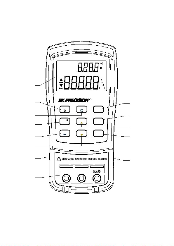
FRONT PANEL OVERVIEW
Figure 1 - Front Panel Display (model 879B shown)
12
Page 15

Front Panel Display Descriptions
1. LCD Display
2. Power ON/OFF Button
3. USB Communication / *Back light button
4. Secondary Display mode (for dissipation
factor(D), quality factor (Q), *phase angle (θ),
*equivalent series resistance (ESR)
measurement) selection button
5. Primary Display mode (for inductance,
capacitance, resistance, and *impedance
measurements) / Parallel or Series
measurement method selection button
6. Tolerance mode / Utility down arrow selection
button
7. Hold Display mode / Record mode selection
button
8. Utility menu button
9. Test Frequency / Utility up arrow selection
button
10. Relative mode / Calibration mode selection
button
11. 12V DC adapter input (use with an external
power adapter (rated 12VDC, 150mA, 4mm
power plug))
Note: Use with included power adapter only.
Use with improper power adapters may
damage instrument.
13
Page 16

WARNING: Before connecting an external
power adapter, please check the battery
compartment in the rear side of the unit. If
a battery is installed, be sure that the
polarity matches the (+) and (-) labels as
indicated inside the battery compartment.
If it is not installed correctly, please
remove the battery and install it with
correct matching polarity as indicated in
the compartment. See “Installing Battery
section for details. DO NOT, at any time,
connect an external power adapter when a
battery is installed incorrectly. Doing so
will damage the instrument and void its
warranty.
12. Input sockets (banana jack inputs) and
terminals for positive, negative, and guard
(see “Guard Terminal” in “SUPPLEMENTAL
INFORMATION” section for details)
13. Standard mini USB port (for remote
controllability)
For model 879B only. Not included on model 878B.
*
”
Front Panel Buttons
All front panel buttons have specific colored labels on
them. They are all marked in white, blue, or yellow
14
Page 17

color. Each color has a specific representation, as
described below:
White – With the exception of the
button, all white colored labels
represent the primary function of that
button; meaning that function will be
set or configured upon pressing it.
Blue – Some of the buttons have a blue label
underneath a white label. This means
the function indicated by the blue
label will be set or configured if that
button is pressed and hold down for 2
seconds.
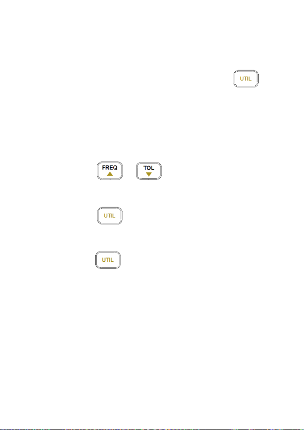
Yellow – There are total of 3 buttons with
yellow labels. They are
. These functions are
exclusively for use when entering
UTIL menu only. See “Utility Menu”
section for details.
15
Page 18

L
C
R
REL
ESR
MAX
AVG
MIN
¦ÈQ
AUTO
D
1%5%10%20%
deg
kHz
PAL
SER
¦Ì
H
p F
¦Ì
RMT
Mk
TOL
DH
n
n
@
OFF
Z
1
2 5
9 10
12
14
16
2021
26
27
28
8
3
2324
25
4
15
11
13
6 7
22
17
18
19
%
29
LCD DISPLAY OVERVIEW
Figure 2 - LCD Indicator Display
LCD Display Descriptions
1. LCRZ – Primary display function indicator (*Z
display)
2. MAX – Maximum reading indicator
3. AVG – Average reading indicator
4. MIN – Minimum reading indicator
5. REL – Relative mode indicator
16
Page 19

6. Θ – *Phase angle indicator for secondary
display
7. Q – Quality factor indicator
8. ESR – *Equivalent series resistance indicator
9. – Secondary display
10. – Beeper tone indicator for tolerance
mode
11. deg – *Phase angle degree indicator
12. Ω – *ESR(ohm) units indicator
13. % - Tolerance percentage indicator
14. kHz – Frequency units indicator
15. PAL – Parallel mode indicator
16. SER – Series mode indicator
17. – Inductance units (Henry) indicator
18. – Capacitance units (Farad) indicator
19. MkΩ – Resistance units (Ohm) indicator
20. RMT – Remote mode indicator
21. – Primary display
22. D – Dissipation factor indicator
23. DH – Data hold indicator
24. AUTO – Auto-ranging indicator
25. TOL – Tolerance mode indicator
26. – Low battery indicator
27. @OFF – Auto power-off indicator
28. 1%5%10%20% - Tolerance sorting
percentage indicator
17
Page 20
29. MAX AVG MIN – Recording mode indicators
For model 879B only. Not included on model 878B.
*
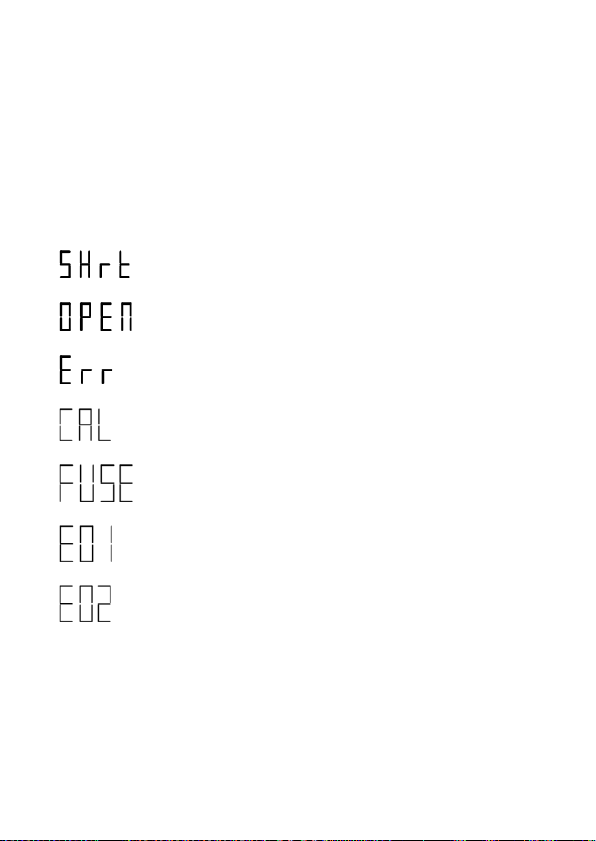
Special Display Indicators
Indicates short connectors
Indicates open connectors
Error indication
Indicates calibration mode
Indicates damaged or open fuse
AD converter error
AD converter error
18
Page 21

POWERING INSTRUMENT
Before beginning to operate the instrument, a power
source is necessary for it to turn on. There are two
methods to power the instrument: Battery and
external source.
Installing Battery
The 878B and 879B LCR meters can use a battery to
provide power to the instrument so that it can be
portable.
The meters use a standard 9V size battery (or
NEDA 1604, JIS006P, IEC6F22 carbon-zinc or
alkaline battery).
To install the battery:
1. Place the meter upside down. Open up the
back-flip stand, and locate the screw that
tightens the battery compartment cover as
indicated in Figure 3. Use a screwdriver to
unscrew and remove the cover.
19
Page 22
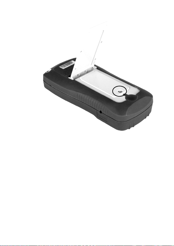
Figure 3 - Back Cover
2. Insert 9V battery into compartment. Note the
positive (+) and negative (-) terminals as
indicated inside the battery compartment (See
Figure 4). Be sure to insert the battery with
matching polarity.
20
Page 23
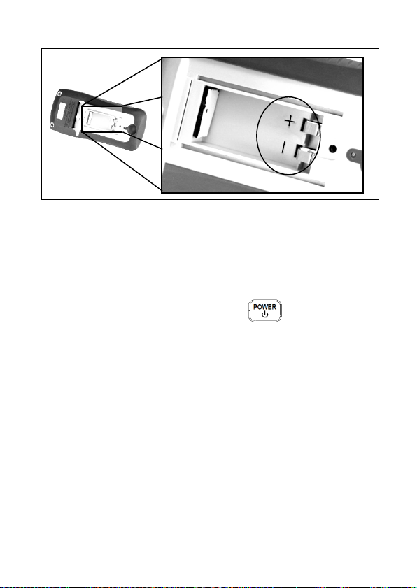
Figure 4 - Battery Compartment
3. Place the battery compartment cover piece by
sliding it into the top slid first. Place screw at
the bottom of the cover piece and tighten
down with a screw driver.
4. Push and hold down the button for 2
seconds to turn on the instrument.
Connecting External Power Source
The 878B and 879B can also be powered using an
external AC adapter. The model 879B comes with
this adapter included in the package, while it is
optional for model 878B.
21
Page 24

For external power, use AC adapter rated for
output 12VDC, 150mA, with a standard 4mm
connector only.
WARNING: Use of incorrect adapters may damage
the instrument. Please use B&K Precision’s adapter
only.
To connect the adapter, do the following:
1. If a battery is installed, please check the
battery compartment again that the polarity of
the battery matches the polarity as indicated
by the labels inside the compartment. If it is
not, please remove and insert the battery with
matching polarity. If a battery is not installed,
continue to the next step.
WARNING: DO NOT, at any time, connect
an external power adapter when a battery
is installed incorrectly (reverse polarity or
non-matching polarity to indicator of
battery compartment). Doing so will
damage the instrument and void its
warranty.
2. Connect the AC adapter connector into the
right side panel of the instrument. See Figure
5 below.
22
Page 25
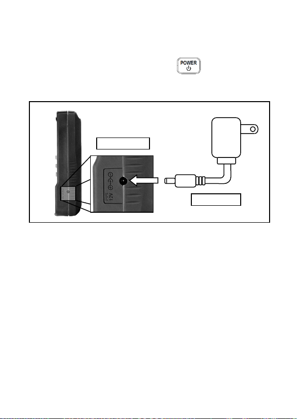
12VDC Input
AC Adapter
Figure 5 - Connecting AC Adapter to Meter
3. Now, connect the AC Adapter socket into an
electrical outlet.
4. Push and hold down the button for 2
seconds to turn on the instrument.
Note: The meter can be operated with a battery
installed while an AC adapter is plugged in at the
same time (As long as the battery is inserted properly
with correct polarity). In this event, the meter will
automatically switch to consume power from the AC
adapter instead of the battery to preserve battery life.
Low Battery Indication
The LCR meter has a low battery indicator to notify
the user when to replace battery. When the display
23
Page 26
starts flashing the indicator, the battery voltage
is below normal working voltage. In this case,
accuracy of the meter will also decrease. It is
recommended that the battery be replaced as soon as
possible before continuing operation. See “Installing
Battery” for instructions.
Backlit Display (model 879B only)
Model 879B LCR meter has a backlit display that
allows you to see the LCD display in dark conditions.
To turn on the back light, press and hold down
button for 2 seconds. Back light will turn on and
brighten the LCD display.
To turn off the back light at any time, press and hold
down button for 2 seconds again. Back light
will turn off and return to normal display.
When Using Battery Power
When the meter is powered using 9V battery, the back
light display will turn on upon holding down the
button for 2 seconds. It will stay at maximum
24
Page 27
brightness for 15 seconds. After another 15 seconds
(30 seconds total from the time of turning on), the
back light will automatically turn off to conserve
battery power.
When Using External Power
When the meter is powered using an external AC
adapter, the back light display will turn on upon
holding down the button for 2 seconds. It will
stay at maximum brightness continuously until the
user presses and holds down the button for 2
seconds again.
Note: If a battery is installed while using an AC
adapter simultaneously, unplugging the AC adapter
will automatically turn off the back light after it has
been lit for 30 seconds.
25
Page 28

OPERATION INSTRUCTIONS
Data Hold
The data hold function allows the user to freeze the display
when pressed, holding the measured value until data hold is
turned off.
Turn On Data Hold
To use data hold, press the button once. The “DH”
indicator will display on the screen when data hold is active.
Turn Off Data Hold
To disable the data hold, press again. The “DH”
indicator will disappear on the screen, and meter will remain
in normal operation mode.
Note: Changing the primary function, secondary function,
or test frequency will automatically turn off the data hold.
Static Recording
This mode is used for recording maximum, minimum, and
average values. It is often useful for testing the range of
values in which a component is expected to fall within upon
measurement.
26
Page 29
Enable Static Recording
Press and hold down the button for two seconds to
enter the static recording mode. The display should indicate
“MAX AVG MIN” simultaneously. This indicates the meter is
in static recording mode and recording is performed
immediately.
Using Static Recording
There are four different modes that can be selected in
static recording. They are indicated by the
descriptions below. These modes can be changed
with each button press. Per each press of the
button, the modes will change and repeat in
the following order:
Recording Mode Maximum Mode Minimum
Mode Average Mode
Recording Mode
This is the default mode when first enabling static
recording. In this mode, the screen will display “MAX
AVG MIN” indicator. At this point, the meter will start
making recordings based on measured values from
27
Page 30

the input sockets or terminals. As recording is
performed, maximum, minimum, and average values
will be stored after a brief moment. A beep tone will
sound once a recording has been stored.
Note: Subsequent beep tones may occur in this mode if
there are new values that are recorded. For example, if a
new maximum is detected, it will beep once again to indicate
that the new value has been stored. Any previously stored
values will be overwritten with the new recorded values.
Maximum Mode
In this mode, the “MAX” indicator will be shown on display.
This indicates that the value in the primary display
represents the recorded maximum value.
Minimum Mode
In this mode, the “MIN” indicator will be shown on display.
This indicates that the value in the primary display
represents the recorded minimum value.
Average Mode
In this mode, the “AVG” indicator will be shown on display.
This indicates that the value in the primary display
represents the recorded average value. This average value
is obtained by taking the maximum and minimum recorded
values and taking the average of the two values.
28
Page 31

Disable Static Recording
To exit this mode, press and hold the button for two
seconds. The “MAX AVG MIN”, “MAX”, “MIN”, or “AVG”
indicator will disappear on screen.
Note: Changing the primary function, secondary function,
or test frequency will automatically turn off static recording.
L/C/R/Z Select Mode
The primary display of the LCR meter is used to
indicate measured values under four different modes
(three modes for model 878B, which excludes Z
(impedance) measurements). These modes are:
L (inductance), C (capacitance), R (resistance), and Z
(impedance).
To change between these four primary modes of
measurement, press the (or for model
878B) button. The modes will change and repeat
upon each button press. On the screen, the indicators
“L”, “C”, “R”, or “Z” (model 879B only) will be
displayed to indicate which mode the meter is in.
29
Page 32

D/Q/θ/ESR Select Mode
The secondary display of the LCR meter is used to
indicate measured values for four various parameters
(two for model 878B, which excludes θ and ESR
measurement mode), which provide additional
information of the component being tested and is
supplementary to the primary mode measurements.
These modes are: D (Dissipation factor), Q (Quality
factor), θ (Phase angle), and ESR (Equivalent series
resistance).
To change between these measurement parameters,
press the (or for model 878B) button.
The parameters for measurement will change and
repeat upon each button press. On the screen, the
indicators “D”, “Q”, “θ” (model 879B only), or “ESR”
(model 879B only) will be displayed to indicate which
secondary mode the meter is in.
Test Frequency
The 879B and 878B LCR meters use an AC signal to test
and measure components at the input sockets or terminals.
With this measurement method, a test frequency must be
selected. The test frequency can affect the accuracy of the
results depending on what frequency is selected and what
type and value of a component is being measured or tested.
30
Page 33

For details on selecting the optimal test frequency for
measurement, refer to the “SUPPLEMENTAL
INFORMATION” section.
Selecting Frequency
To select or change the test frequency, push the
button once. With each press, the test
frequency will be indicated on the secondary display
of the meter. This will remain displayed until a
different function for the secondary display is selected.
The selectable test frequencies for 879B meter are:
100 Hz, 120 Hz, 1 kHz, and 10 kHz.
The selectable test frequencies for 878B meter are:
120 Hz and 1 kHz.
Relative Mode
Relative mode is used when the user wants to “zero”
the meter based on a reference value or wants to
obtain a reading that is relative to a reference value.
For example, if test leads are used in the
measurement, the user may want to set a reference
with the test leads inserted into the input terminals so
31
Page 34

that any measurements taken will not take into
account the test leads.
Setup Relative Mode
To setup the relative mode, simply press the
button once. The value that is on the display will
immediately be stored as the “reference” value. This
reference value will be used for all measurements so
as long as the meter is in relative mode, which is
indicated by the “REL” indicator on the display.
A common use of relative mode is to “zero” out the
meter. With nothing connected to the input sockets
and terminals, simply press the button once and
the meter will “zero” out, meaning all display reading
will become 0.
To make measurements within a specific test setup or
with test leads, it is recommended that the user first
have test leads or wires connected to the meter in the
fashion that they desire. Then, press the button
once to “zero” out the meter as reference. This way,
any measurements taken would not be affected by the
test leads or setup.
32
Page 35

Disable Relative mode
To disable relative mode, simply press the
button once more. The “REL” indicator will disappear,
which indicates the relative mode is disabled.
Note: Changing the primary function, secondary function,
or test frequency will automatically disable relative mode.
Tolerance
The tolerance mode feature is specifically used for
component sorting purposes. Users who need to test
and sort through a large number of components will
find this function quite helpful.
Tolerance Range
The tolerance function is configured primarily by range
in percentage, meaning a percentage is used to
define whether a measured value is within tolerance
or out of tolerance.
(for model 879B) Selectable tolerance range is: 1%,
5%, 10%, and 20%.
(for model 878B) Selectable tolerance range is: 1%,
5%, and 10%.
33
Page 36

Setup Tolerance
1. Select the primary measurement mode based
on the type of components to be measured.
This is done by pressing the (or
for model 878B) button to configure the
desired measurement mode.
Note: Be sure to select the correct
measurement mode, as tolerance mode
cannot be activated unless the correct mode
is selected. For example, if the component is
a capacitor, be sure to select “C” for
capacitance. If not, tolerance mode will not
be activated following the proceeding steps
below.
2. Insert the component to be used as the
“standard” reference value. Another words,
insert a known “good” component that will be
used for testing against all other components.
(See Figure 6 for illustration)
Note: The tolerance mode cannot be
activated unless the meter senses a
component is connected to either the input
sockets or terminals.
34
Page 37

WARNING: If the component to be measured
is a capacitor, be sure that the capacitor is
fully discharged BEFORE inserting it into the
input sockets or terminals. For large
capacitors, it may take longer periods of time
for a full discharge. Inserting a charged or
partially charged capacitor into the meter’s
input sockets or terminals may produce an
electric hazard and may also damage the
instrument, making it unusable.
Figure 6 - Inserting Component to Inputs
35
Page 38

3. Once the desired measured reading is
displayed, press the button once to
store the reading as the “standard” value or
test reference value. At this point, the “TOL”
will be displayed on the screen, indicating that
the tolerance mode is activated.
Note: Any value which appears on the LCD
display, such as DH (data hold) or
MAX/MIN/AVG, can also be used as the
“standard” value or test reference value for
sorting components.
4. To select the tolerance range, press the
button once more. For each button
press, the meter will cycle through the
tolerance range percentage in this order: 1%,
5%, 10%, 20% (model 879B only). These
percentage ranges will also be indicated on
the LCD display by the indicators “1%”, “5%”,
“10%”, or “20%” (model 879B only)
respectively. The component to be tested for
will be verified with the tolerance within the
selected % of the “standard” value or test
reference value (as configured from step 3).
5. Within a few seconds, an audible tone will be
heard.
36
Page 39

One single “beep” or tone means the
component is within tolerance.
Three “beeps” or tone means the component
is out of tolerance.
Disable Tolerance Mode
To disable or exit out of tolerance mode, simply press
and hold down the button for two seconds. The
“TOL” and/or the percentage indicators “1%”, “5%”,
“10%”, or “20%” (for model 879B only) will disappear
on the LCD display.
Note: Changing the primary function, secondary function,
or test frequency will automatically disable tolerance mode.
Utility Menu
The LCR meter has a built-in utility menu that allows
you to configure some user preferences and settings.
The buttons used to set and control the menu are
colored in yellow. They are , , and
. User can configure the beep sound, auto
37
Page 40

SETTINGS /
PARAMETERS
bEEP
ON / OFF
AoFF
5 / 15 / 30 / 60 / OFF
PuP
PrE / Set
dEF
yES / NO
power-off timing, power-up state, and reset instrument
to default settings.
Entering Utility Menu
Press and hold down the button for two
seconds or until the primary display shows “bEEP”.
This indicates the meter is currently in the utility menu.
Configuration and Settings
There are four different menu options and
configurable settings under each option. Below is a
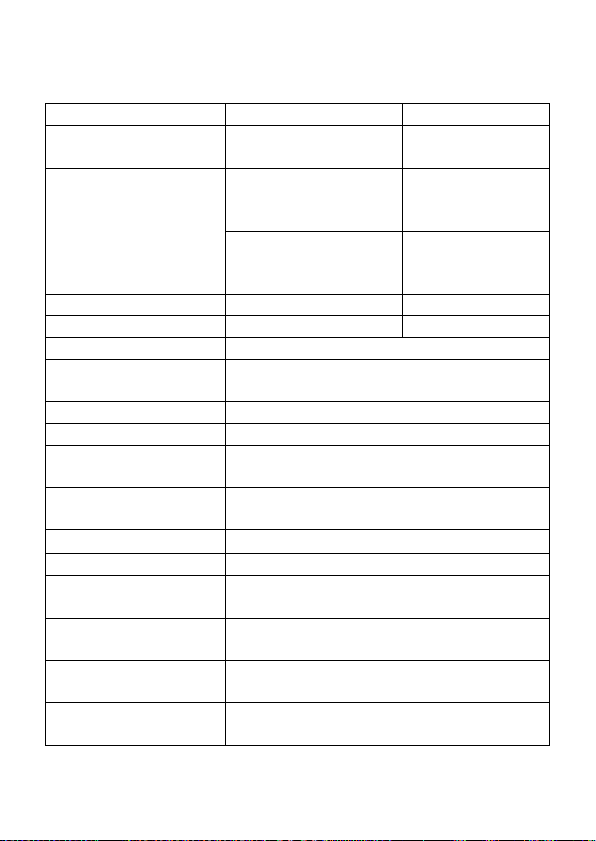
table that lists these options and settings.
Table 1 - Utility Menu Options and Settings
MENU OPTIONS
38
Page 41

The four menu options allow users to control the beep
sound setting (bEEP), auto power off setting (AoFF),
power-up state settings (PuP), and resetting
instrument to default settings (dEF).
By default, the first option after entering the utility
menu is “bEEP”. The primary display indicates the
menu option, and the secondary display indicates the
current settings or parameters configured for the
selected option. To change the settings or
parameters, use the and arrow keys. To
change or select a different menu option, press the
button once. For each button press, the
meter will traverse through each menu options and
will repeat itself in the following order:
bEEP AoFF PuP dEF
Note: The settings and parameters are temporarily
“remembered” once the button is pressed to
select a different menu option. To save all settings
permanently, exit the menu using the save and exit
method. With the exception of “bEEP” and “AoFF”
settings, in which case under these settings, changes
are temporarily saved even when exiting the menu
without saving. (See “Exit Utility Menu” section for
details).
39
Page 42
Beep Sound Setting (bEEP)
The “bEEP” menu option allows the user to enable or
disable the beep sound for every key press.
Note: This option only disables the beep sound for
each key press. It does not disable the beep sound
for “Static Recording” and “Tolerance” mode, as well
as the “auto power-off” warning.
To turn ON the beep, push either the or
arrow keys until the secondary display shows “ON”.
To turn OFF the beep, push either the or
arrow keys until the secondary display shows “OFF”.
Default Setting: ON
Auto power-off Setting (AoFF)
The “AoFF” menu option allows the user to select the
auto power-off timer. This timer is always counting
continuously. It resets every time a button is pressed
or if an action occurred. If the meter is left untouched
or unattended, the timer will count until the configured
time is up. This is particularly important if the user
wants to preserve battery life or run the meter
continuously without interruption.
40
Page 43

SECONDARY
DISPLAY
REPRESENTATION
5
5 minutes
15
15 minutes
30
30 minutes
60
60 minutes
OFF
No timer. Manual
power off only
Note: When the timer has reached the configured
time, the meter will make an audible “beep” sound
continuously for 10 seconds before auto power-off.
To stop the “beep” sound, simply press any button to
resume operation and reset the timer count.
The available timer settings are: 5 minutes, 15
minutes, 30 minutes, 60 minutes, and off.
When the primary display shows “AoFF”, push the
or button to select the timer setting. The
settings will be shown on the secondary display as
follows:
Table 2 - Auto Power-off Options
Default Setting: 15
41
Page 44

When the auto power-off option is set to any of the
configured settings in Table 2 (except for “OFF”),
upon exiting the utility menu the LCD display will have
a “@OFF” indicator. This means a timer has been set
for auto power-off.
Note: When an external 12VDC AC adapter is used
to power the instrument, the auto power-off feature
will automatically be disabled. This is indicated on the
LCD display when the “@OFF” indicator disappears.
Under this condition, the meter will remain powered
ON continuously. In this state, powering off the
instrument would require manually pushing and
holding down the button for 2 seconds.
When external power is removed, the meter will
automatically re-enable auto power-off again and
“@OFF” indicator will re-appear if a time has been set
from the “AoFF” option of the utility menu.
Power-up State (PuP)
The “PuP” menu option allows user to configure the
power-up state of the LCR meter, allowing user to
restore settings saved into internal EEPROM memory
at power-up.
42
Page 45

In the utility menu, when the primary display shows
“PuP”, there are two settings selectable and shown on
the secondary display. “PrE” and “SEt”.
Default Setting: PrE
Storable Settings
• Primary function mode (i.e. L/C/R)
• Test frequency
• Secondary function mode (i.e. D/Q)
• Tolerance mode state
• Reference value for Tolerance mode
• Relative mode state
• Reference value for Relative mode
Configure and Save Power-up State
Follow the below procedure to setup and store a
power-up state into internal memory.
1. Before entering into the utility menu, configure
all the settings and parameters desired for
power up state. Do this by turning on any
modes and setting values as desired. (Only
the settings listed above in “Storage Settings”
are stored). If the meter is currently in the
utility menu, exit first and setup the desired
43
Page 46
settings for recalling at power-up. (see “Exit
Utility Menu” for details)
2. Once settings are configured, enter/re-enter
the utility menu by holding down the
button for 2 seconds.
3. Traverse through the utility menu until you see
“PuP” on the primary display. The secondary
display should also show “PrE”.
4. In order to save the current meter settings for
power-up state into internal memory, use
either or button to change the
settings so that the secondary display shows
“SEt”.
5. Press button to select the next menu
option. Once all other utility options are
configured, exit the utility menu by holding
down button for 2 seconds.
6. The meter has now saved all current settings
into internal memory. At next power-up, the
meter will turn on and recall the saved
settings.
Note: The meter allows one set of settings to be
stored into memory. Therefore, the same
44
Page 47

procedure is used to overwrite previously stored
settings into memory.
Prevent Overwrite of Stored Settings
In the utility menu, the “PuP” option default setting is
always “PrE”. This represents “previous settings”.
Keeping this setting will prevent the meter from
overwriting previously stored settings for power-up
state. Therefore, when entering the utility menu, be
sure not to change to “SEt” to prevent overwriting any
previously stored power-up settings.
Reset Default Settings (dEF)
The last option in the utility menu allows you to reset
the meter to default settings. When the primary
display shows “dEF”, the secondary display will show
“NO” by default. The meter will also default this
setting to “NO” to prevent accidental reset of
instrument settings.
Default Setting: No
To reset the meter to default settings, first select the
“dEF” menu option by using the use button to
browse through the utility menu. When the primary
45
Page 48

Settings
Default Configuration
Primary Function
C (Capacitance)
Secondary Function
None
Measurement Method
SER (Series)
Test Frequency
1 kHz
Beep
On
Auto Power-off
15 (15 minutes)
Power-up State
PrE
Reset Default Settings
No
display shows “dEF”, either press or
button to change the setting so that the secondary
display shows “yES”. Upon saving and exiting the
utility menu, the instrument will automatically reset
back to its original settings. Below is a table of all the
settings that will be restored.
Table 3 - Instrument Default Settings
Note: In the case where under “PuP” option, “SEt” is
selected and “dEF” is set to “yES”, the “PuP” setting
has priority over the “dEF” setting. This means the
instrument will not be set back to default upon saving
and exiting the utility menu. Instead, the power-up
settings will be stored and will be recalled upon the
next power-up of the instrument.
46
Page 49

Exit Utility Menu
There are two methods for exiting the utility menu.
One saves all the changed settings before exiting, and
the other exits the menu without saving any changes.
Saving and Exiting
To save all utility menu option settings and to exit the
menu, press and hold down the button for 2
seconds. After this, the meter will exit the menu, and
all settings will be saved.
Exiting without Saving
If user decides to exit the utility menu without making
any changes or saving any changes to “PuP” or
“dEF”, it can be done by simply pressing any front
panel buttons except , , , and
. Note that settings that are changed under
“bEEP” and “AoFF” options are still temporarily set
until the next power-up of the instrument.
47
Page 50

Parallel and Series Measurement Mode
The LCR meter offers the option to select between parallel
or series measurement mode. Depending on which mode is
selected, the method to measure the component will be
different. Additionally, one measurement mode may provide
better accuracies over the other measurement mode
depending on the type of component and the value of the
component to be tested. For more details, refer to the
“SUPPLEMENTAL INFORMATION” section.
Default Settings
For Capacitance and Resistance measurements, the
default measurement mode is parallel.
For Inductance measurements, the default
measurement mode is series.
Selecting Measurement Mode
The measurement mode of the meter is displayed by
the indicators “SER” or “PAR” on the LCD screen.
“SER” means meter is in series measurement mode.
“PAR” means meter is in parallel measurement mode.
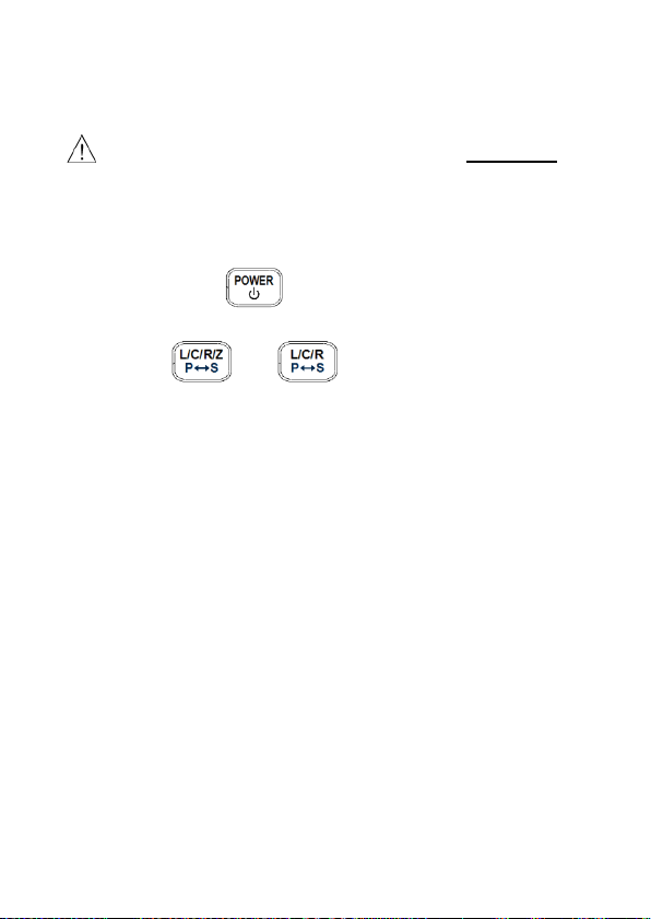
To toggle between the two modes, press and hold
down (or for model 878B) button for 2
48
Page 51

seconds. The indicators on the display should toggle
between “SER” and “PAR”.
Calibration
Calibration is available on all modes. It is
recommended that to achieve optimal readings,
calibration should be done before making any
measurements.
To enter calibration mode, simply press and hold
down the button for 2 seconds. A calibration
prompt will be displayed. There are two types of
calibration available. One is the open circuit
calibration. The other is the short circuit calibration.
To exit calibration mode, simply press and hold down
the button for 2 seconds again.
Open Calibration
Open calibration can be done when meter first enters
into calibration mode. If the input sockets or terminals
have nothing connected, the display should show
Figure 7. Also, “REL” indicator will be blinking on the
display. This is to prompt the user that the meter is
waiting for an action. At this point, open calibration
49
Page 52

will be done when the button is pressed once.
Within a few seconds, the meter will return to normal
display and meter will be calibrated based on the test
frequency and settings selected prior to entering the
calibration mode.
Figure 7 - Open Calibration
Short Calibration
Short calibration can be done when meter first enters
into calibration mode. If the input sockets or terminals
have nothing connected, the display will be like Figure
7. For short calibration, simply put a shorting bar or a
short piece of conductive metal (i.e. paper clip) across
the “+” and “-“ input sockets or terminals. Within 2
seconds, the meter will display the same screen as
50
Page 53
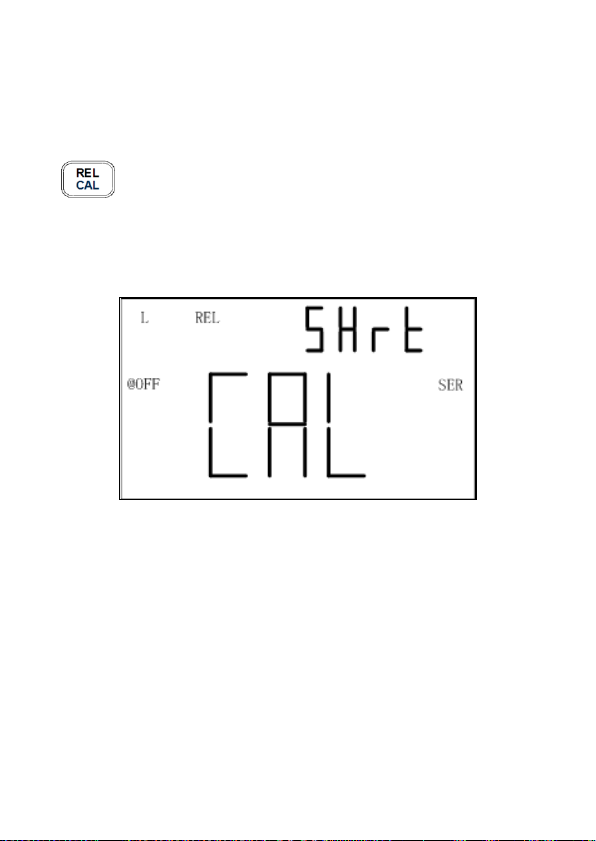
Figure 8, which prompts for a “short”. Also, “REL”
indicator will be blinking on the display. This is to
prompt the user that the meter is waiting for an action.
At this point, short calibration will be done when the
button is pressed once. Within a few seconds,
the meter will return to normal display and meter will
be calibrated based on the test frequency and settings
selected prior to entering the calibration mode.
Figure 8 - Short Calibration
Quick Procedure
Below is an example of steps to follow to do both
open and short calibration.
1. Select the primary function mode for
measurement (i.e. L/C/R/Z).
2. Select the test frequency for measurement.
51
Page 54

3. Select the measurement mode (i.e. Series or
Parallel)
4. Once all settings are configured, hold down
button for 2 seconds to enter into
calibration mode.
5. First, do open calibration. Follow instructions
under “Open Calibration” section.
6. Next, do short calibration. Follow instructions
under “Short Calibration” section.
7. Now, the meter should go back to normal
display and user may proceed to take
measurements of components.
Recommendations
To achieve optimal measurement results, both open
and short calibration should be done. It is highly
recommended to calibrate extremely high or low
values for L, C, R and Z before making precision
measurements.
Notes:
1. If test frequency is changed, calibration
should be done again before making precision
measurements. Once calibration is done on a
selected test frequency, calibration data will
remain until power off.
52
Page 55

2. Either open or short calibration is not
associated with measurement function,
therefore changing the test function does not
require re-calibration.
3. Re-calibration may be necessary depending
on many factors such as prolonged use,
changing environments, and contact variation
(i.e. alligator test leads or socket contacts).
USB
The USB button (or for model 878B) are
used for remote communication. See “REMOTE
COMMUNICATION” section for details.
Automatic Fuse Detection
The LCR meter has an internal fuse that protects the
inputs from severely damaging the instrument. When
the meter detects that the protective fuse is open, the
“FUSE” indicator will appear on the primary display
(see Figure 9) and an internal “beep” will sound
continuously. In this situation, none of the function
buttons can be operated and all other meter functions
will be disabled.
53
Page 56

Figure 9 - Fuse Display
In the event that the above screen is displayed, a fuse
replacement is required. Turn off the meter by
pressing and holding down the button for 2
seconds. If this does not power off the meter, remove
external AC adapter if that is used and/or remove the
battery from the battery compartment. Refrain from
further operation until fuse is replaced. Please
contact B&K Precision for assistance.
54
Page 57

QUICK START GUIDE
CAUTION
• Do not measure a capacitor that is not fully
discharged. Connecting a charged or partially
charged capacitor to the input terminals will
damage the instrument.
• When measuring within a circuit, the circuit must be
de-energized before connecting the test leads.
• When used in a dusty environment, the instrument
should be wiped and cleaned regularly.
• Do not leave the instrument exposed to direct heat
from the sun for long periods of time.
• Before removing the cover, ensure that the
instrument is disconnected from any circuit and is
powered OFF.
55
Page 58
Note:
To achieve optimum precision for all L, C, and R
measurements at either the highest or lowest
ranges, calibrate the meter before testing. See
“Calibration” section for details.
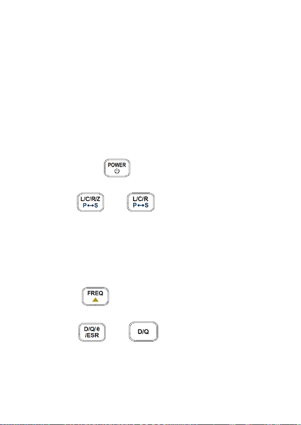
Inductance Measurement
1. Press down button for one second to turn
on the meter.
2. Press (or for model 878B) button
until “L” is displayed on the screen to select
inductance measurement.
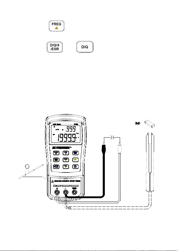
3. Insert an inductor into either the input sockets or
connect alligator leads into the banana jack input
terminals and connect the clips to the component
leads as illustrated in Figure 10.
4. Press button until the desired test
frequency is displayed on screen.
5. Press (or for model 878B) button
to select between D factor, Q factor, θ angle, or
56
Page 59

ESR measurement for secondary display. (θ and
ESR function for model 879B only)
6. Read the display readings for inductance
measured values and selected measured values
on secondary display.
Figure 10 - Inductance Measurement Setup
57
Page 60
Capacitance Measurement
WARNING Fully discharge capacitor BEFORE
inserting it into the instrument. Failure to do this may
result in damage to the meter and may cause
electrical hazards.
1. Press down button for one second to turn
on the meter.
2. Press (or for model 878B) button
until “C” is on the screen to select capacitance
measurement.
3. CAUTION: BEFORE inserting a capacitor or
capacitive component into the input sockets
or terminals, be sure to fully discharge the
component. Some larger capacitive
components may take longer to discharge. In
these cases, please allot enough time for a full
discharge. If proper discharging of the
component is not done correctly, it will
damage the input terminals of the meter.
4. Insert the DISCHARGED capacitor or capacitive
component into the input sockets or connect
alligator leads into the banana jack input terminals
and connect the clips to the component leads as
illustrated in Figure 11.
58
Page 61
5. Press button until the desired test
frequency is displayed on screen.
6. Press (or for model 878B) button
to select between D factor, Q factor, θ angle, or
ESR measurement for secondary display. (θ and
ESR function for model 879B only).
7. Read the display readings for capacitance
measured values and selected measured values
on secondary display.
Figure 11 - Capacitance Measurement Setup
59
Page 62
Resistance Measurement
1. Press down button for one second to turn
on the meter.
2. Press (or for model 878B) button
until “R” is on the screen to select resistance
measurement.
3. Insert resistor or resistive component into the
input sockets or connect alligator leads into the
banana jack input terminals and connect the clips
to the component leads as illustrated in Figure 12.
4. Press button until the desired test
frequency is displayed on screen.
Note: This meter does not provide a DC
resistance measurement of the component. It
uses an AC signal for measurement. For this
reason, some applications or device under test
may not give correct readings if they are designed
for measurement in DC.
5. Read the display readings for resistance
measured values.
60
Page 63
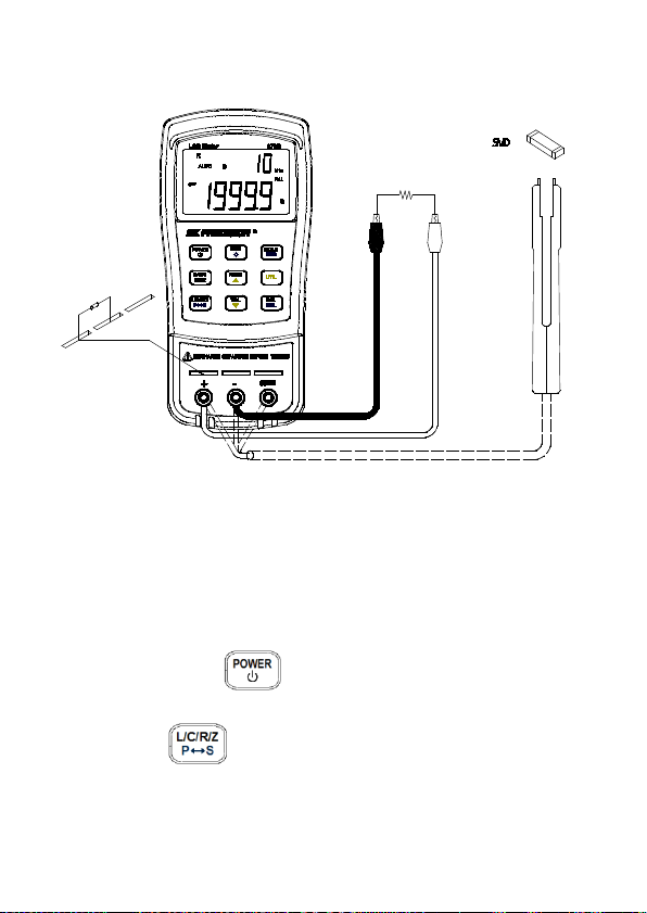
Figure 12 - Resistance Measurement Setup
Impedance Measurement (Model 879B only)
1. Press down button for one second to turn
on the meter.
2. Press button until “Z” is on the screen to
select impedance measurement.
61
Page 64

+ -
R
!
AUTO
@
OFF
SMD
D
PAL
kHz
Z
USB
D/Q/
/ESR
L/C/R/Z
POWER
REC
REL
HOLD
CAL
P
S
FREQ
TOL
UTIL
LCR Meter
879B
3. Insert component into the input sockets or
connect alligator leads into the banana jack input
terminals and connect the clips to the component
leads as illustrated in Figure 13.
4. Press button until the desired test
frequency is displayed on screen.
5. Read the display readings for impedance
measured values.
Figure 13 - Impedance Measurement Setup
62
Page 65

REMOTE COMMUNICATION
The meter has the capability to communicate with a
PC over the mini USB interface. Upon installation of a
USB driver, the PC can control the instrument over
virtual COM (RS-232). The mini USB communication
interface of the meter is designed in full duplex and
has a 64-byte input and output buffer, making it
reliable and efficient for data transmission.
Connecting Instrument to PC
Follow the below procedures for connection setup.
1. Download the USB drivers from
www.bkprecision.com
2. With the included mini USB cable, connect the
mini USB end to the LCR meter and the other
end to an available USB port on the PC (see
Figure 14).
3. When Windows recognize the USB
connection, do not follow the default Windows
driver installation wizard. Simply run the
setup file from the downloaded USB drivers
and follow the prompt to install drivers.
4. When completed, the computer will recognize
the instrument as a USB (virtual COM) device,
meaning it will be detected as a serial COM
.
63
Page 66

port. Windows will automatically assign a
COM port to the instrument. Please verify
which COM port Windows has assigned by
going into “Device Manager”.
Figure 14 - USB Connection
64
Page 67

USB (Virtual COM) Configuration
The USB will be recognized as a virtual COM on the
PC, thus serial port settings must be configured
properly for remote communication to be successful.
Below are the settings used by the 878B and 879B
meters.
• Baudrate: 9600
• Data bits: 8
• Parity: None
• Stop bits: 1
• Flow Control: None
USB Operation
There are two modes that describe the operation of
the meter when it is setup for remote communication.
They are remote mode and auto fetching mode.
Remote Mode
Upon connecting to the instrument, sending any
commands listed in the “Command Protocols
will automatically set the LCR meter into remote
mode. In remote mode, the LCD display will show the
” section
RMT indicator. When this is shown, all front panel
65
Page 68

buttons will be disabled, except for the (or
for model 878B) button.
To exit remote mode and go back to local mode,
press the (or for model 878B) button
once. The
display. Pushing the same button once more will put
the meter into auto fetching mode, which is described
in the next section.
Auto Fetching Mode
When connected to a PC, the meter can be
configured to auto-fetching mode. This means, the
meter will continuously fetch data to the PC after
every measurement cycle is completed. It fetches
data from measured readings of primary display and
secondary display, as well as tolerance compared
results. This mode is useful when doing quick data
logging using PC.
RMT indicator will disappear on the LCD
66
Page 69

Enable/Disable Auto Fetching
To toggle between enabling and disabling auto
fetching, press the (or for model
878B) button. When enabled, data will be fetched
constantly after every measurement cycle is
completed. When disabled, no fetched data will be
available.
Note: Alternatively, auto fetching mode can be
disabled when a remote command is sent to the
instrument, turning it back into remote mode. In this
event, the
display, and auto fetching will be disabled
automatically. To re-enabled auto fetching again in
this state, first press the (or for model
878B) button once to exit out of remote mode and
return to local mode. Then, press the button once
more to have it set to auto fetching mode again.
RMT indicator will appear on the LCD
Command Protocols
Overview of Command Type and Format
All commands are entered in either the upper case or
the lower case. There are two types of the meter
programming commands: IEEE 488 common
67
Page 70

commands and Standard Commands for
Programmable Instruments (SCPI). Some commands
are device-specific to the meter. They are not included
in the version 1999.0 of the SCPI standard. However,
these commands are designed with the SCPI format
in mind and they follow the syntax rules of the
standard.
Common Command Format
The IEEE 488 standard defines the common
commands as commands that perform functions like
reset and system query. Common commands usually
come with the asterisk “*” character, and may include
parameters. Some examples of Common command
like: *IDN?, *GTL, *LLO.
SCPI Command Format and Query Format
The SCPI commands control instrument
functions. A subsystem command has a hierarchical
structure that usually consists of a top-level (or root)
keyword, one or more lower level keywords, and
parameters. The following example shows a
command and its associated query:
A. FUNCtion:impa L
Select L as primary parameter
B. FUNCtion:impa?
Return primary parameter
68
Page 71

function is a root level keyword with the second level
keyword, impa, and L is the command parameter. The
query command ends with a question mark “?”.
Note: SCPI stems from IEEE488.1 and IEEE 488.2.
Although the IEEE 488.2 standard addressed some
instrument measurements, it principally dealt with
common commands and syntax or data formats.
Please refer to the IEEE488.2 and SCPI reference
manual for more information.
Termination Character
A terminator is a character sent by a host, which
identifies the end of a command string. A valid
terminator consists of two-byte data:
<CR> (Carriage Return, ASC(&H0D)) or <LF> (Line
Feed, ASC(&H0A)) or <CR><LF>
Responding Message
Returned result
After the meter executes a query command, the return
of the result will be in the following format:
<Result> + <CR> <LF>
For example, in auto fetching mode, the meter will
send the measured data automatically when the
69
Page 72

Data Type
Explanation
Example
<NR1>
An integer
+800,-200,100,-50
This numeric
point
This representation
exponent
A parameter for
or “1” for Boolean
measurement cycle is completed. The format of the
printed data will be shown as the following:
<Primary measured data, Secondly measured
data, Tolerance Result > + <CR> <LF>
Data Types
Returned message is an ASCII string from the meter
responding to a query. A query is a command
accompanied a “?” mark. Table 4 below explains the
different data types.
Table 4 - Data Type of Responded Messages
<NR2>
<NR3>
<Boolean>
representation has
an explicit radix
has an explicit
radix point and an
Boolean setting.
Always return “0”
70
+1.56,-0.001,10.5
+2.345678E+04
-1.345678E-01
ON or OFF
Page 73

query command
A string is used as
short literal form
Text Symbol
Meaning
[ ]
Option; can be omitted
|
Exclusive OR
< >
Defined element
( )
Comment
?
Question mark
Separated two command
keywords
<Literal>
command
parameters with
HOLD
SCPI Commands
This section described all the SCPI commands
supported by the meter. The meter can accept both
upper case and lower case commands.
Table 5 - SCPI Symbol Conventions
:
71
Page 74

Description: Queries the instrument ID.
version>, <serial number>
Description: Set measurement frequency
Set 100Hz frequency
Description: Query the measurement frequency
only)
*IDN?
Response: <instrument model>, <firmware
*LLO
Local Lockout. This means that all front panel
buttons, including the "USB" key is not available.
*GTL
Go to local.
Puts the meter into the local state,
clearing the remote state and front panel lockout.
FREQuency Subsystem
FREQuency <value>
Parameters: Parameters are 100, 120, 1000,
10000 (879B only) or
100hz,120hz,1khz,10khz (879B
only)
Example: FREQuency 100hz
FREQuency?
Response: 100hz, 120hz, 1khz, 10khz (879B
72
Page 75

Description: Select primary parameter
Selects L as primary parameter
Description: Query primary parameter
only),NULL
Description: Select secondly parameter
Select D as secondly parameter
Description: Query secondly parameter
ESR (879B only), NULL
FUNCtion subsystem
FUNCtion:impa < L | C | R | Z >
(Z for model 879B only)
Example: FUNCtion:impa L
FUNCtion:impa?
Response: Return L, C, R, Z (879B
FUNCtion:impb < D | Q | THETA | ESR >
(THETA and ESR for model879B only)
Example: FUNCtion:impb D
FUNCtion:impb?
Response: Return D, Q, THETA (879B only),
73
Page 76

Description: Set equivalent mode
Set series mode
Description: Query the equivalent mode
string
Description: Enable or disable relative
CALCulate:RELative:STATe ON
Description: Query the relative state
Response: Return ON or OFF
FUNCtion:EQUivalent < SERies | parallel |
PAL >
Parameters: SERies — serial mode
Parallel — parallel mode
Pal — parallel mode
Example: FUNCtion:EQUivalent SERies
FUNCtion:EQUivalent?
Response: Return “SER” or “PAL” format
CALCulate subsystem
CALCulate:RELative:STATe < ON | OFF >
function
Example:
CALCulate:RELative:STATe?
74
Page 77

Description: Query the relative value
Response: Return <NR3> or “-----” format string
Description: Enable or disable tolerance function
Example: CALCulate:TOLerance:STATe ON
Description: Query the tolerance state
Response: Return ON or OFF
Description: Query the nominal value of
Response: Return <NR3> or “-----” format string
Description: Query the percent value of
Response: Return <NR3> or “-----” format string
Description: Set tolerance range
Set 1% tolerance range
CALCulate:RELative:VALUe?
CALCulate:TOLerance:STATe < ON | OFF >
CALCulate:TOLerance:STATe?
CALCulate:TOLerance:NOMinal?
tolerance
CALCulate:TOLerance:VALUe?
tolerance
CALCulate:TOLerance:RANGe < 1 | 5 | 10 |
20 >
Parameters: 20 (879B only)
Example: CALCulate:TOLerance:RANGe 1
75
Page 78
Description: Query the tolerance range
“BIN4” or “----” format string
Description: Enable or disable recording
ON
Description: Query the recording state
Response: Return ON or OFF
Description: Query the maximum value of
string
Description: Query the minimum value of
string
CALCulate:TOLerance:RANGe?
Response: Return “BIN1”, “BIN2”, “BIN3”,
CALCulate:RECording:STATe < ON | OFF >
function
Example: CALCulate:RECording:STATe
CALCulate:RECording:STATe?
CALCulate:RECording:MAXimum?
recording function
Response: Return <NR3, NR3> or “-----” format
CALCulate:RECording:MINimum?
recording function
Response: Return <NR3, NR3> or “-----” format
76
Page 79

Description: Query the average value of
string
Description: Query the present value of
string
Description: Returns the primary, secondary
Example: FETCh?
CALCulate:RECording:AVERage?
recording function
Response: Return <NR3, NR3> or “-----” format
CALCulate:RECording:PRESent?
recording function
Response: Return <NR3, NR3> or “-----” format
FETCh Subsystem
FETCh?
display value and tolerance
compared result of device’s output
buffer.
Response: Return <NR3, NR3, NR1> format
string
77
Page 80

Command
Parameter
Explanation
FREQuency
<Value>
Set Test Frequency
FREQuency?
Query Test Frequency
FUNCtion
:impa
<Literal>
Select primary display
parameter
:impa?
Query primary display
parameter
:impb
<Literal>
Select secondary display
parameter
:impb?
Query secondary display
parameter
:EQUivalent
<Literal>
Set equivalent mode
:EQUivalent?
Query equivalent mode
CALCulate
:RELative
:STATe
<Boolean>
Enable/disable relative
function
:STATe?
Query relative state
:VALUe?
Query relative value
:TOLerance
:STATe
<Boolean>
Enable/disable tolerance
function
:STATe?
Query tolerance state
:NOMinal?
Query nominal value of
tolerance
:VALUe?
Query percent of tolerance
:RANG
<Value>
Set tolerance range
:RANGe?
Query tolerance range
:RECording
Summary of Supported SCPI Commands
Table 6 - Summary of SCPI Commands
78
Page 81

:STATe
<Boolean>
Enable/disable recording
function
:STATe?
Query recording state
:MAXimum?
Query max. value of
recording
:MINimum?
Query min. value of recording
:AVERage?
Query average value of
recording
:PRESent?
Query present value of
recording
FETCh?
Return data any time last
reading is valid
Error Codes
In certain situations, errors may occur, and an error
code will be displayed on the meter. Below defines
the error description based on the error code.
E10: Unknown command
E11: Parameter Error
E12: Syntax Error
79
Page 82

SUPPLEMENTAL INFORMATION
This section provides supplemental information for
user consideration when operating the LCR meters.
Some recommendations and explanations are
provided to help aid in the use of some functions and
features, in which can help the user gain optimal and
accurate measurement results.
Selecting Test Frequency
Test frequency can greatly affect the results of
measurement reading, especially when measuring
inductors and capacitors. This section provides some
recommendations and suggestions to consider.
Capacitance
When measuring capacitance selecting, the right
frequency is important in obtaining the most accurate
measurement results. Generally, a 1 kHz test
frequency is used to measure capacitors that are 0.01
µF or smaller. For capacitors that are 10 µF or larger,
a lower frequency of 120 Hz is used. Following this
trend, high test frequencies are best for testing very
low capacitance components. For large capacitance
components, low frequency would be optimal. For
80
Page 83

example, if the capacitance of the component is to be
in the mF range, than selecting 100 Hz or 120 Hz for
test frequency would give much better results. The
results will also be obvious because if the same
component was tested with 1 kHz or 10 kHz, the
measured readings may look erroneous on the
display.
In all cases, it is best to check with the manufacturer’s
data sheet in order to determine the best test
frequency to use for measurement.
Inductance
Typically, a 1 kHz test frequency is used to measure
inductors that are used in audio and RF circuits. This
is because these components operate at higher
frequencies and require that they be measured at
higher frequencies such as 1 kHz or 10 kHz.
However, a 120 Hz test signal is used to measure
inductors that are used for applications such as filter
chokes in power supplies, in which are typically
operated at 60 Hz AC (in U.S.) with 120 Hz filter
frequencies.
In general, inductors below 2 mH should be measured
at 1 kHz frequency while inductors above 200 H
should be measured at 120 Hz.
81
Page 84

In all cases, it is best to check with the manufacturer’s
data sheet in order to determine the best test
frequency to use for measurement.
Selecting Series or Parallel Mode
Just as test frequency can greatly affect measurement
results, selecting between series or parallel
measurement mode can also affect the accuracy of
the meter, especially for capacitive and inductive
components. Below are some recommendations to
consider.
Capacitance
For most capacitance measurement, selecting
parallel mode is the best. Hence, the meter defaults
to this mode when selecting capacitance mode. Most
capacitors have very low dissipation factor (high
internal resistance) compared to the impedance of the
capacitance. In these cases, the paralleled internal
resistance has negligible impact upon the
measurement.
Though in some cases, series mode would be
preferred. For instance, measuring a large capacitor
would require using series mode for optimal reading.
Otherwise, the meter may show the reading results as
82
Page 85

out of accuracy or erroneous. Series mode is use
because large capacitors often have higher
dissipation factor and lower internal resistance.
Inductance
For most inductance measurement, selecting series
mode is the best. Hence, the meter defaults to this
mode when selecting inductance mode. This is
because in this mode, accurate Q (quality factor)
reading can be obtained from reading low Q inductors
and ohmic losses are significant.
Though in some cases, parallel mode would be
preferred. For example, iron core inductors operating
at higher frequencies where hysteresis and eddy
currents become significant would require
measurement in parallel mode for optimal results.
Accuracy Discrepancies
In some special cases, inaccuracies may occur in the
measurement of capacitive, inductive, and resistive
components.
83
Page 86

Capacitance
When measuring capacitors, it is always most
desirable if the dissipation factor is low. Electrolytic
capacitors inherently have a higher dissipation factor
due to their normally high internal leakage
characteristics. In some cases, if the D (dissipation
factor) is excessive, measurement accuracy may
degrade and even read out of specification.
Inductance
Some inductors are intended to operate at a certain
DC bias to achieve a certain inductance value.
However, the 878B and 879B LCR meters cannot
produce such biasing scheme and external biasing
should not be attempted because external power
would be applied to the instrument and cause serious
damage to the meter. Therefore, in some cases,
measured inductance reading may not agree with
manufacturer’s specification. It is important to check if
specification pertains to DC biasing or not.
Resistance
When measuring resistance of devices, it is important
to know that there are two types or ways of
measurement. One type is DC resistance
measurement. Another type is AC resistance
measurement. The 879B and 878B uses AC
resistance measurement method and does not
84
Page 87

provide an option for DC resistance measurements.
Therefore, when measuring a resistive component
that is designed to be measured with DC, readings will
be incorrect or inaccurate. Before using the meter to
measure resistance, please verify whether the DUT
(device under test) requires DC or AC resistance
measurement method. Depending on the method,
results will vary greatly.
Guard Terminal
One of the input sockets and terminals is labeled as
“GUARD”. This terminal does not have to be used in
all instances for the meter to make measurements.
But in some instances, it is very useful. Guard
terminal generally serves two purposes.
If user is using test leads, the guard terminal can be
used to connect to the shielding of the test leads.
Doing so can be useful when making large resistive
component measurements. For example, when
measuring a 10 MΩ resistor with test leads, at the
high range the reading may seem to be unstable as a
few digits may continuously be changing. Having the
shield of the test leads connected to the guard
terminal will help stabilize the reading in some
instances.
85
Page 88

Guard terminal is also used to minimize noise and to
help minimize parasitic effects coming from the
component to be measured, thus allowing high
precision results.
86
Page 89

SPECIFICATIONS
Below are some remarks in regards to all
specifications pertaining to both 878B and 879B LCR
meters.
*Specifications are subject to change without notice.
Notes:
1. Measurement performed at the test socket.
2. Measurements performed after correct open
and short calibration.
3. DUT and test leads must be properly shielded
to guard if necessary.
4. Based after 30 minutes of warm up time and
operated at 23 °C + 5 °C, <75% R.H.
5. Q value is the reciprocal of DF.
6. Accuracies based within 10% to 100% of full
scale of range; values outside of range should
be used as reference only.
7. Based on battery powered operation.
8. --- means parallel or series measurement
mode.
87
Page 90
Items
879B
878B
Measurement
Parameters
L/C/R/Z/D/Q/θ/ESR
L/C/R/D/Q
Test Frequency
100 Hz, 120 Hz,
(test setting)
120 Hz, 1 KHz
100Hz, 120.048Hz,
(actual frequency)
120.048 Hz,
frequency)
Tolerance Mode
1%, 5%, 10%, 20%
1%, 5%, 10%
Backlit Display
Yes
None
Test Signal Level
≈ 0.6 Vrms
Measuring
Circuit Mode
Series mode / Parallel mode
Basic accuracy
0.5%
Ranging Mode
Auto
Measuring
Terminals
3 terminals with sockets
Measurement Rate
1.5 reading/second (range auto
search not included)
Response Time
Response Time: ≈680 ms/DUT
Auto Power-Off
5, 15, 30, 60 mins, None
Operation
Temperature
32 °F to 104 °F(0 °C to 40 °C);
0-70 % R.H.
Storage
Temperature
-4 ° F to 122 °F (-20 °C to +50 °C);
0-80 % R.H.
Low Battery
Indication
≈ 6.8 V
Battery Life
≈16 hours using Alkaline Battery @ 1
kHz with 100 Ω DUT, with backlight
General Specifications
Accuracy is 0.02%
of actual frequency
1 kHz, 10 kHz
1 kHz, 10 kHz
(test setting)
1 kHz (actual
88
Page 91

off
Power
Consumption
≈ 28 mA (under full power battery) for
operation/ 2 µA after Power-off.
Power
1) DC 9V Battery
(Load 50 mA Min.)
Dimensions
(L/W/H)
7.5 x 3.5 x 1.6”
(190 × 90 × 41 mm)
Weight
0.7 lbs. (330 grams)
Inductance
Frequency = 100 Hz*/120 Hz
Range
Display
Accuracy
<0.5)
Mode
1000 H
1000.0 H
1.5% + 3
digits
1.5% +
50 digits
Parallel
400 H
399.99 H
0.7% + 2
digits
0.7% +
50 digits
Parallel
40 H
39.999 H
0.7% + 2
digits
0.7% +
50 digits
---
4000 mH
3999.9 mH
0.5% + 1
digits
0.5% +
50 digits
Series
400 mH
399.99 mH
0.6% + 2
digits
0.6% +
50 digits
Series
40 mH
39.999 mH
0.9% + 2
digits
0.9% +
50 digits
Series
4 mH
3.9999 mH
2.8% + 3
digits
2.8% +
50 digits
Series
Requirements
2)Ext. AC Adapter: DC
12 Vmin –15 Vmax.
Accuracy Specifications
Max
Lx
DF(Dx
Measurement
89
Page 92

Frequency = 1 kHz
Range
Display
Accuracy
<0.5)
Mode
100 H
100.00 H
1.5% + 3
digits
1.5% +
50 digits
Parallel
40 H
39.999 H
0.7% + 2
digits
0.7% +
50 digits
Parallel
4000 mH
3999.9 mH
0.7% + 2
digits
0.7% +
50 digits
---
400 mH
399.99 mH
0.5% + 1
digits
0.5% +
50 digits
Series
40 mH
39.999 mH
0.6% + 2
digits
0.6% +
50 digits
Series
4000 μH
3999.9 μH
0.9% + 2
digits
0.9% +
50 digits
Series
400 μH
399.99 μH
2.8% + 3
digits
2.8% +
50 digits
Series
Frequency = 10 kHz*
Range
Display
Accuracy
<0.5)
Mode
1000 mH
1000.0 mH
1.5% + 3
digits
1.5% +
50 digits
Parallel
400 mH
399.99 mH
0.7% + 2
digits
0.7% +
50 digits
---
40 mH
39.999 mH
0.5% + 1
digits
0.5% +
50 digits
Series
4000 μH
3999.9 μH
0.6% + 2
digits
0.6% +
50 digits
Series
Max
Lx
DF(Dx
Measurement
Max
Lx
DF(Dx
Measurement
90
Page 93
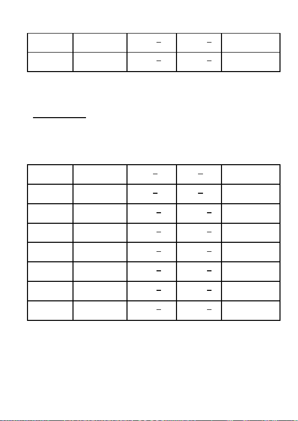
400 μH
399.99 μH
0.9% + 2
digits
0.9% +
50 digits
Series
40 μH
39.99 μH
2.8% + 3
digits
2.8% +
50 digits
Series
Capacitance
Frequency = 100 Hz*/120 Hz
Range
Display
Accuracy
<0.5)
Mode
20 mF
20.000 mF
8% + 3
digits
8% + 50
digits
Series
4000 μF
3999.9 μF
2% + 2
digits
2% + 50
digits
Series
400 μF
399.99 μF
0.7% + 2
digits
0.7% +
50 digits
Series
40 μF
39.999 nF
0.5% + 1
digits
0.5% +
50 digits
Series
4000 nF
3999.9 nF
0.5% + 1
digits
0.5% +
50 digits
---
400 nF
399.99 nF
0.5% + 2
digits
0.5% +
50 digits
---
40 nF
39.999 nF
0.7% + 1
digits
0.7% +
50 digits
Parallel
4 nF
3.9999 nF
2.5% + 2
digits
2.5% +
50 digits
Parallel
Max
Cx
91
DF(Dx
Measurement
Page 94
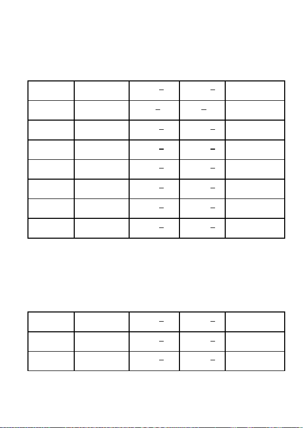
Frequency = 1 kHz
Range
Display
Accuracy
<0.5)
Mode
1000 μF
1000.0 μF
3.7% + 3
digits
3.7% +
50 digits
Series
400 μF
399.99 μF
2% + 2
digits
2% + 50
digits
Series
40 μF
39.999 μF
0.7% + 2
digits
0.7% +
50 digits
Series
4000 nF
3999.9 nF
0.5% + 1
digit
0.5% +
50 digit
Series
400 nF
399.99 nF
0.5% + 2
digits
0.5% +
50 digits
---
40 nF
39.999 nF
0.5% + 2
digits
0.5% +
50 digits
---
4000 pF
3999.9 pF
0.7% + 2
digits
0.7% +
50 digits
Parallel
400 pF
399.9 pF
2.5% + 2
digits
2.5% +
50 digits
Parallel
Frequency = 10 kHz*
Range
Display
Accuracy
<0.5)
Mode
100 μF
100.00 μF
3.9% + 5
digits
3.9% +
50 digits
Series
40 μF
39.999 μF
3.7% + 3
digits
3.7% +
50 digits
Series
4000 nF
3999.9 nF
0.7% + 2
digits
0.7% +
50 digits
Series
Max
Max
Cx
Cx
DF(Dx
DF(Dx
Measurement
Measurement
92
Page 95
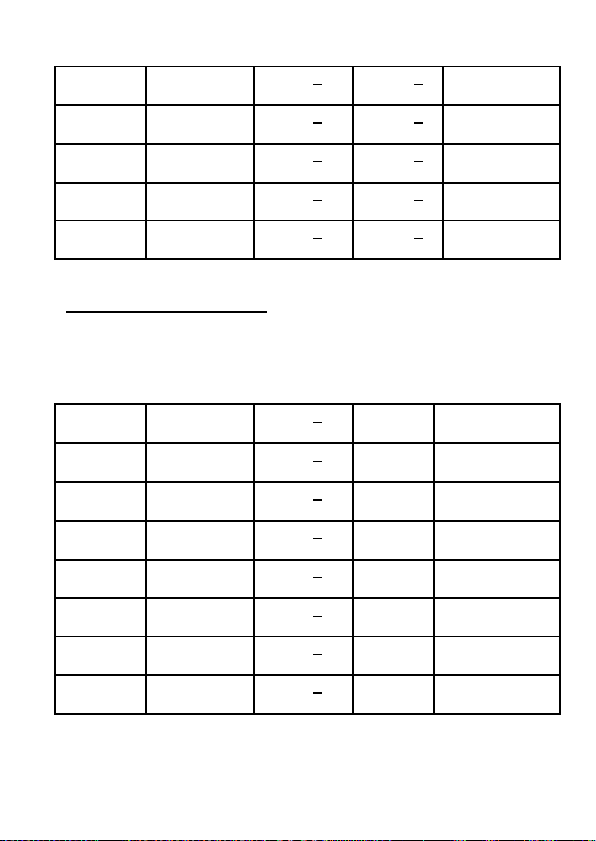
400 nF
399.99 nF
0.5% + 2
digits
0.5% +
50 digits
Series
40 nF
39.999 nF
0.5% + 1
digit
0.5% +
50 digit
---
4000 pF
3999.9 nF
0.5% + 2
digits
0.5% +
50 digits
---
400 pF
399.99 pF
0.7% + 2
digits
0.7% +
50 digits
Parallel
40 pF
39.99 pF
2.5% + 2
digits
2.5% +
50 digits
Parallel
Resistance/Impedance*
Frequency = 100 Hz*/120 Hz/ 1 kHz/10 kHz*
Range
Display
Accuracy
Accuracy
Mode
10 MΩ
10.000 MΩ
5.5% + 3
digits
±3.2°
Parallel
4000 kΩ
3999.9 kΩ
2.5% + 2
digits
±1.5°
Parallel
400 kΩ
399.99 kΩ
0.7% + 2
digits
±0.4°
Parallel
40 kΩ
39.999 kΩ
0.5% + 2
digits
±0.3°
---
4000 Ω
3999.9 Ω
0.5% + 2
digits
±0.3°
---
400 Ω
399.99 Ω
0.5% + 2
digits
±0.3°
Series
40 Ω
39.999 Ω
0.7% + 2
digits
±0.4°
Series
4 Ω
3.9999 Ω
2.0% + 2
digits
±1.2°
Series
Max
R/Zx
93
Θ*
Measurement
Page 96

ESR*
Frequency = 100 Hz*/120 Hz/ 1 kHz/10 kHz*
Range
Display
Accuracy
Mode
1000 Ω
999.9 Ω
0.5% + 2
digits
Series
100 Ω
99.99 Ω
0.5% + 2
digits
Series
10 Ω
9.999 Ω
0.7% + 2
digits
Series
1 Ω
.9999 Ω
2.0% + 2
digits
Series
* = Model 879B only
Max
ESR
Measurement
94
Page 97

MAINTENANCE
WARNING: Do not perform any service by yourself.
Service should only be done by qualified personnel
and trained technicians.
Service
If the instrument fails to operate, check battery and
test leads. Replace them as necessary. If the
instrument still cannot work, verify with the operating
instructions to make sure correct procedures are
followed.
When servicing, use specified replacement parts only.
Note: The meter must be completely turned off while
replacing the battery. Refer to “Installing Battery”
section for details.
Cleaning
WARNING: To avoid electrical shock or damaging
the meter, prevent water from getting inside the case.
In the case that water gets inside, remove the battery
immediately and do not operate the instrument
95
Page 98

immediately. Doing so will immediately damage the
instrument and void it’s warranty.
Before cleaning this meter, make sure the power is
OFF and remove external AC adapter if one is used.
To clean the meter, wipe the dirty parts with a soft
cloth soaked with diluted neutral detergent. Avoid
having the instrument too wet to prevent the detergent
from penetrating into the inside components of the
meter, causing damages. After cleaning, make sure
the instrument is completely dried before operating it
again.
96
Page 99

SERVICE INFORMATION
Warranty Service: Please go the support and service section on our
website www.bkprecision.com
the original packaging with proof of purchase to the address below.
Clearly state on the RMA the performance problem and return any leads,
probes, connectors and accessories that you are using with the device.
Non-Warranty Service: Please go the support and service section on our
website www.bkprecision.com
the original packaging to the address below. Clearly state on the RMA the
performance problem and return any leads, probes, connectors and
accessories that you are using with the device. Customers not on an open
account must include payment in the form of a money order or credit card.
For the most current repair charges please refer to the service and support
section on our website.
Return all merchandise to B&K Precision Corp. with pre-paid
shipping. The flat-rate repair charge for Non-Warranty Service does
not include return shipping. Return shipping to locations in North
America is included for Warranty Service. For overnight shipments
and non-North American shipping fees please contact B&K
Precision Corp.
Include with the returned instrument your complete return
shipping address, contact name, phone number and
description of problem.
to obtain a RMA #. Return the product in
to obtain a RMA #. Return the product in
B&K Precision Corp.
22820 Savi Ranch Parkway
Yorba Linda, CA 92887
www.bkprecision.com
714-921-9095
97
Page 100

LIMITED WARRANTY
B&K Precision Corp. warrants to the original purchaser that its
products and the component parts thereof, will be free from defects
in workmanship and materials for a period of three years from date
of purchase.
B&K Precision Corp. will, without charge, repair or replace, at its
option, defective product or component parts. Returned product
must be accompanied by proof of the purchase date in the form of a
sales receipt.
To help us better serve you, please complete the warranty
registration for your new instrument via our website
www.bkprecision.com
Exclusions: This warranty does not apply in the event of
misuse or abuse of the product or as a result of unauthorized
alterations or repairs. The warranty is void if the serial number
is altered, defaced or removed.
B&K Precision Corp. shall not be liable for any consequential
damages, including without limitation damages resulting from loss
of use. Some states do not allow limitations of incidental or
consequential damages. So the above limitation or exclusion may
not apply to you. This warranty gives you specific rights and you
may have other rights, which vary from state-to-state.
B&K Precision Corp.
22820 Savi Ranch Parkway
Yorba Linda, CA 92887
www.bkprecision.com
714-921-9095
98
 Loading...