

Page 1

INSTRUCTION MANUAL
MANUAL DE INSTRUCCIÓNES
Dual Display LCR Meter
Model 878A / 879
Medidor LCR de Doble Exhibicion
Visual
Modelos 878A/ 879
Page 2
1
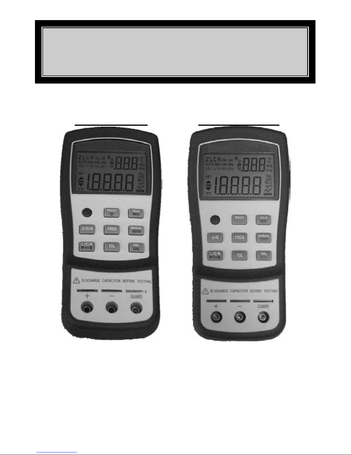
DUAL DISPLAY L/C/R METER
INSTRUCTION MANUAL
Model-A = 879
Model-B = 878A
Page 3

2
TABLE OF CONTENTS
PAGE
Safety
3
Introduction
5
Front Panel Illustration
6
LCD Display Ill ustration
7
How to Operate
9
Operati ng Instruct ions
13
Data Hold
13 Static Recording
13 Dissipation Factor / Quality Factor/ Phase Angle
13 Test F requency
14 L/C/R function selector
14 Relative
14 Tolerance
14 Auto/manual ranging
15 Automatic Fuse Detection
15
Parallel / Series Mode 15
Calibration
16 Auto Power Off/ Disable Auto Power Off
17 Low Battery Indicat ion
17 Backlit Display
17 Communication
18
General Specification
19
Electrical Specification
20
Maintenance
28
Spanis h M anual
33
Page 4
3
SAFTEY
Read "SAFETY INFORMATION" before using this meter.
NOTE
The meter is a hand-held, battery-operated instrum e nt fo r testing
inductance, capacitance and resistance. If this device is damaged or
something i s missing, cont act the place of purchase immediately.
This manual contains information and warnings must be followed to
ensure safe operation as well as to maintain the meter in a safe
condition. Some common international electrical symbols used in this
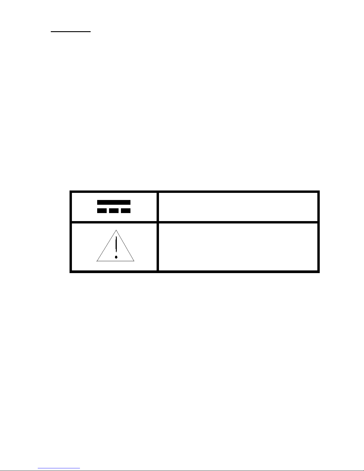
manual are shown below Table:
DC - Direct Current
See Explanation In The Manual
Table 1-1. International Electrical Symbols
Before using the meter, read the following safety information carefully.
In this manual, "WARNING", is reserved for conditions and actions
that pose hazard(s) to the user; "CAUTION", is reserved for conditions
and actions that may damage your meter.
Page 5

4
SAFETY INFORMATION
To ensure that you use this device safely, follow the safety guidelines
listed below:
•
This meter is for indoor use, altitude up to 2,000 m.
•
The warnings and precautions should be read and well
understood before the instrument is used.
•
Use this device only as specified in this manual; otherwise,
the protection provided by the meter may be impaired.
•
When measuring in-circuit components, first de-energize th e
circuits befo r e connecting to the test lead s.
•
Disc h arge capacitor b efore testing.
•
The meter is safety-certified in compliance with EN61010
(IEC 1010-1) Installation Category II (CAT. II) 50 V,
Pollution Degree 2 envi ronment.
•
Use the meter only as specified in this manual. Otherwise,
the protection provided by the meter may be impaired.
•
The power for the meter is supplied with a single standard
9V battery. But also a line operation is possible using a 12V
AC to DC ad aptor. If a power adaptor is selected, plea se be
sure t o u s e fu lfi lled t h e s af et y req u i rem en t s of a r ele van t IEC
standard.
Page 6

5
INTRODUCTION
This 19,999-count L/C/R hand-held meter is a special microprocessorcont rolled meter for mea su rin g func tion s of in duct anc e, cap acit anc e and
resistance. Extremely simple to operate, the instrument not only takes
absolute parallel mode measurements, but also capable of series mode
measu rement . The meter provi des di rect a nd accu rate m easuremen ts of
inductors, capacitors and resistors with different testing frequencies. It is
selecta ble for auto and manual ranging.
Front panel pushbuttons maximize the convenience of function and
feature selection such as data hold; maximum, minimum and average
record mode; relative mode; tolerance sorting mode; frequency and
L/C/R selection.
The test data can be transferred to PC through an optiona l full isolat ed
optical RS232C interface.
Backlight display for easy reading in dark places (Model-A only).
A tilt stand provides position flexibility for viewing and operating the
meter. The over-molding rubber case protects the meter to be stronger.
With single 9V battery operation is standard for the meter, a DC 12V
pow er ada ptor can also be used as an optio na l power input.
Page 7
6
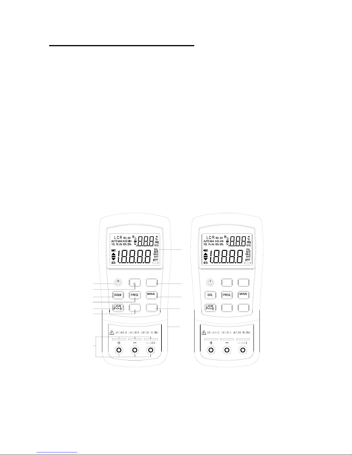
FRONT PANEL ILLUSTRATION
1.
LCD display
2.
Power ON/OFF button
3.
RS232 and Ba cklit button
4.
Dissipation factor, Quality factor and Phase an gl e selection
button
5.
Test frequency selection button
6.
Inductance, Capacitance and Resistance function selection
button. Parallel and series mode selection button
7.
Tolerance mode s electio n button
8.
Data h old, Maxi mum, Minim um and Averag e readi ng select ion
button
9.
Range selection button
10.
Relative mode and Calib ration selection button
11.
DC 12V adaptor inp ut
12.
Input sockets and Terminals
REL
CAL
AUTO
TOL
AUTO
TOL
REL
CAL
RS232
HOLD
REC
HOLD
REC
RS232
1
8
9
10
11
2
3
4
5
6
7
12
u
u
RS232 RS232
u
u
Figure-1. Front panel for Model-A and Model-B.
Page 8
7
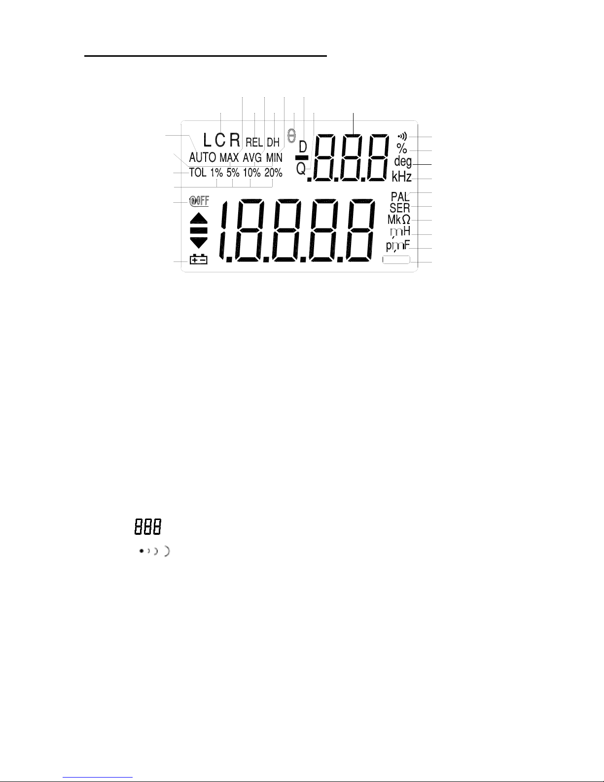
LCD DISPLAY ILLUSTRATION
12
13
14
15
22
24
23
21
25
26
1
16
17
18
19
20
2
3 4 6 10
119875
RS232
u
u
Figure 2. LCD Display.
1.
AUTO:
Auto-ranging indicator
2.
LCR:
L, C or R function indicator
3.
MAX:
Maximum reading indicator
4.
AVG:
Average reading indicator
5.
REL:
Relative mode indicator
6.
MIN:
Minimum reading indica t or
7.
DH:
Data hold indicator
8.
Θ:
Phase angle indicator (Model-A only )
9.
Q:
Quality factor ind icator
10.
D:
Dissipation factor indicator
11.
:
Secondary display
12.
:
Beeper tone indicator for tolerance mode
13.
%:
Tolerance (percentage) indicator
14.
deg:
Phase Angle degree indicator (Model-A only )
15.
kHz:
Fr eque nc y i nd icator
16.
MAX AVG MIN:
Recording mode indicators
17.
TOL:
Tolerance mode indicator
18.
1%5%10%20%:
Tolerance sorting (percent) indicator
Page 9
8
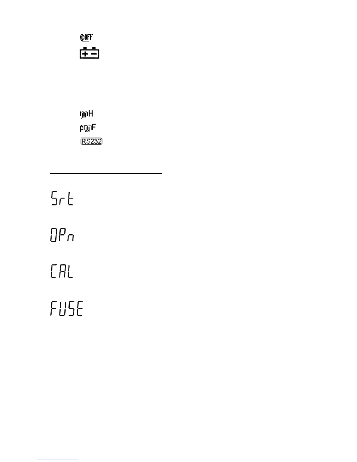
19.
:
Auto power- off indicator
20.
:
Low battery indicator
21.
PAL:
Para l lel mode indicator
22.
SER:
Series mode indicato r
23.
MkΩ:
Resi stance (Ohm) indicator
24.
:
Inductance (Henry) indicator
25.
:
Capacitan ce (Farad) indicator
26.
:
RS232 ind icator
Special Indication Charac ters
: Indicates short connectors
: Indicat es open connectors
: Indicates calibration mode
: Indicat es damaged or open fuse
Page 10

9
HOW TO OPERATE
Caution
•
When measuring within a circuit, the circuit must be deenergiz ed before conn ectin g the test leads.
•
The instrument that used in dusty environment should be
wiped and cleaned regularly.
•
Do not leave the instrument exposed to direct heat from the
sun or beat s ource for long periods.
•
Before removing the cover, ensure that the instrument is
disconnected from any circuit and in power "OFF" position.
Note:
For achieving optimum precision for all L, C and R
measurements at either the highest or lowest ranges, it is
recommended to calibrate the meter b efore testing.
Page 11
10
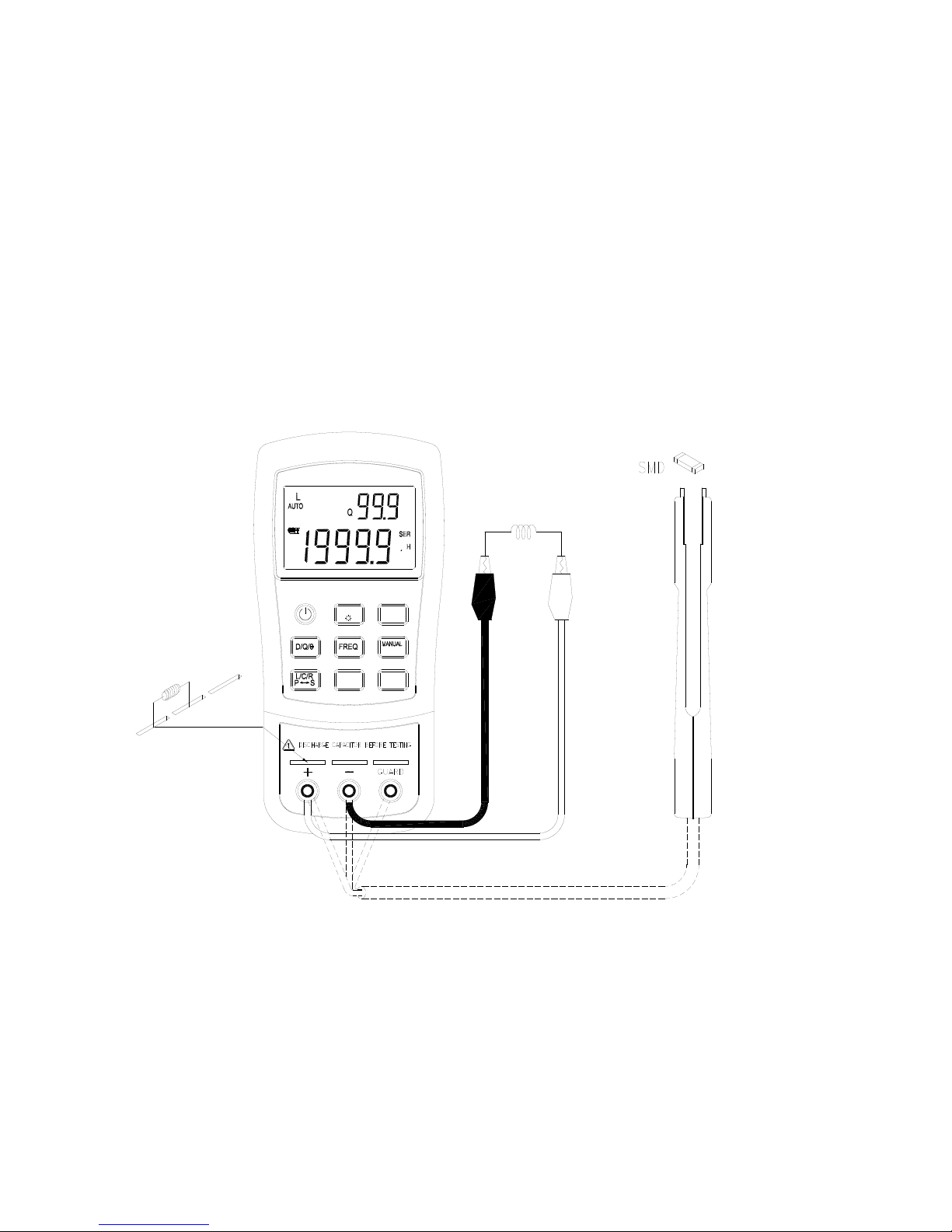
I
nductance Measurement
1.
Press the "
POWER
" button to tu rn on the meter.
2.
Press “
L/C/R
” button to sel ect inductance measurement.
3.
Insert a n induc tor int o componen t recept acle s ocket or co nnect th e
test clip to the component leads as required.
4.
Press “
FREQ
” button to select testing frequency.
5.
Press “
D/Q
” button to select Q factor for secondary display.
6.
Read the display readings for inductance value and quality factor.
AUTO
TOL
REL
CAL
HOLD
REC
RS232
u
Figure-3. Induct an c e M easurement.
Page 12

11
Capacitance Measurement
1.
Press "
POWER
" button to turn on the meter.
2.
Press “
L/C/R
” button to select cap acitan ce measurement .
3.
Insert a capacit or into th e component recepta cle socket or connect
the test clip to the component leads as required.
4.
Press “
FREQ
” button to select testing frequency.
5.
Press “
D/Q
” button to select D factor for secondary display.
6.
Read the display readings for capacitance value and dissipation
factor.
Warning
To avoid electrical hazards, discharge the capacitor to be tested before
measuring.
AUTO
TOL
REL
CAL
HOLD
REC
RS232
Figure-4. Capacitance Measurement.
Page 13

12
Resistance Measurement
1.
Press "
POWER
" button to turn on the meter.
2.
Press “
L/C/R
” button to sel ect Resistance measurement.
3.
Insert a resistor into the component receptacle socket or connect
the test clip to the component leads as required.
4.
Press “
FREQ
” button to select testing frequency (this meter will
not give you the DC resi stance of a comp o nent).
5.
Read the display readings for resistance value.
AUTO
TOL
REL
CAL
HOLD
REC
RS232
Figure-5. Resistance Measurement.
Page 14

13
OPERATING INSTRUCTIONS
Data Hold
This data hold function allows the operat or to freeze the di s play. To
enter this mode, press the “HOLD” pushbutton; press again to release.
Static Recording
Press the “
REC
” pushbutton for more than one second to enter the static
recording mode. The maximum and minimum readings are then stored
in memory, whil e a beepi ng to ne i s produced when a new tested value
has been recorded. Push the same button to cycle through the
maximum, minimum and average of the present readings. The
MAX
,
MIN
or
AVG
indicators will display on LCD will turn on to indicate
what value is being displayed. When ever the “
MAX AVG MIN
”
indicators appear on the LCD simultaneously, the display reading is
always a present value.
To exit this mode, press and hold the pushbutton for more than one
second.
Notes:
1. Static rec ording cap tures on ly stable val ues and upd ates the m emory;
it will not record any “
OL
” (overload) value for any of the
L/C/R
functions. In addition, the meter will not record which values are
below 50 counts in Capacitance measurement.
2. Static recording is only available in manual ranging; however,
activation while in auto-ranging will automatically set meter to
manual ran ging and cause ca libration p rompts to be displayed in the
recommended ranges.
Dissipation Factor / Quality Factor/ Phase Angle
The “
D/Q/Θ
” value can be displayed interchangeably by pressing the
“
D/Q/Θ
” button when the meter is set to Inductance or Capacitance
mode. It does not apply to resistance measurement. The ph ase angle i s
available on Model-A only.
Page 15

14
Test Frequency
Default testing frequency is 1KHz. Push “
FREQ
” key to se l ect the
desi r ed test f r equency.
L/C/R Function Selector
Simply press the “
L/C/R
” pushbutton to select the desired L, C or R
function.
Relative
Press the “REL” key t o enter the relat ive mode and sto r es the display
reading as a reference value. It will then display all subsequent readings
in relative t o referen ce valu e. Press the button again to exit the relative
mode.
Notes:
1.
The rela tive mode can ’t be activated if the display value i s either
“
OL
” or “
0000
”.
2.
Relative mode is only available in manual ranging; however,
activation while in auto-ranging will automatically set the meter to
manual ranging and cause calibration prompts to be displayed in
the recommen ded ranges.
3.
The relative mode cannot be activated if the meter is set at autoranging with data hold activated.
Tolerance
There are 1%, 5%, 10% an d 2 0% tolerance range. To enter th is
tolerance mode, insert the appropriate component as a standard value
into the socket or connect the component to the test probes, then pre s s
the “TOL” pushbutton to set this va lue, as the standard reference
tolerance. Similarly, any value which appears on the LCD display, such
as DH or MAX/MIN/AVG, can be u sed as a standard value to sort
components. Press this button again to cycle through 1%, 5%, 10% and
20% tolerance as desire.
This funct i on is des ign ed for con ven ient comp onent sorting. An audible
tone will sound whenever the component under test exceeds the setting
Page 16

15
toleran ce. Con versely, a single ton e of “Be” indica tes the component is
within the setting tolerance.
Notes:
1.
The tole ra n c e mod e c an ’t be act i vat ed if th e t est ed di sp la y is ei t h er
“
OL
” or “
0000
”; nor can it be activated the tested capacitance
value is below 10 counts.
2.
Tolerance mode is only available in manual ranging; however,
activati on while in aut o-ranging will automatically set the meter to
manual ranging and cause calibration prompts to be displayed in
the recommen ded ranges.
3.
The tolerance mode can’t be activated if the meter is set at autoranging with data hold mod e ac tivated.
4.
For 20% selection is available on Model-A only.
Auto / Manual Range
The auto-ranging mode is default status when the meter is powered on.
For sp ecifi c measu r ement, pr ess “AUTO” button to select man ual
ranging. To return to the auto -ranging mode, press and hold the
“AUTO” button for more than one second.
Automatic Fuse Detection
When t he meter detects that the protective fuse is open, the “FUSE”
character will appear and an internal beep will sound continuously. In
this situation, none of the function keys can be operated and all other
meter functions will be discontin ued. Fuse replacem ent i s requi red.
Figure-6. Fuse Det ection
Parallel / Series Mod e
The meter is capable of displaying Parallel and Series mode data fo r all
ranges. The parallel mode is default for Capacitance and Resistance
Page 17

16
measurements, and the series mode is default for Inductance
measurement. Press “L/C/R” button for more than 1 second to toggle
“SER” and “PAL” mode.
Calibration
Calibration is available to all ranges. Simply press and hold “
CAL
”
button for more than one second to enter the calibration mode and
calibration prompts will be displayed. Follow the prompts for open
connector (
) or short connector ( ) connection and press the
“
CAL
” button. After calibration is completed, the meter will be
restored to normal display and ready for n ormal usage.
Figure-7. Open/ Short Calibration
The function calibrates the meter’s internal parameters as well as
external connector residues for further measuring. It is highly
recommen ded t o calibra te extremel y high or low ranges for L, C an d R
before making precision measurements. Calibration prompts will be
displayed automatically every time those ranges are manually or
functionally selected, (e.g.
REL, TOL, REC
etc.), and calibration is
recommended. Simply follow the open connector (
) or short
connector (
) instruction and then press the “
CAL
” button. You
may skip the calibration by pressing the “
D/Q
” button.
Notes:
1.
Changing measurement frequencies is handled the same as
selecting a different hardware range, and so automatic calibration
prompts will be displayed in the recomm ended ranges.
Page 18

17
2.
Be sure to use same testing position after short calibration.
Auto Power Off/ Disable Auto Power Off
When the meter has not been used for five minutes after the last
operat io n was made, a long “beep” tone will sound. The meter will then
automatically enter a “sleep” mode and there will be no display on the
LCD. To reactivate the meter, simply press any pushbutton. After reactivating.
When th e meter i s to be used for long peri od, the aut o power-off c an b e
disabled by pressing and holding “
L/C/R
” button while turning meter
ON. Release the button, and press any button again. The
symbol
will be disappeared to confirm that the auto power off has been disabled.
By using a 12V AC adaptor as an optional power source, auto power off
is disabl e d au tomatically.
Note: It i s recommended that the meter should always be switched off
when not in use.
Low Batt ery Indication
When the “ “ symbol flashes on the display, the battery voltage is
below normal working voltage and is weakening . Repl ace battery with a
new one t o maintain accurac y of the meter.
Backlit Display
(Model-A only)
Press and hold “ “ key for more than one second to toggle backlit
ON/OFF.
Page 19

18
Communication
This meter has communication capability. By using the optional RS23 2
package (AK 87X), with full optical isolated cable and software. This
function will assist user to record data easily.
Referring the following procedures to set up the communication
between your meter and personal computer.
1.
Fixes one side of cable to the meter, and the text side shall be
facing up. To connect the 9-pin’s terminal of cable to
communica tion port 1 or 2 of personal comput er. See the
Figure-
8
.
2.
Press “RS232” button to enable this interface. You will find that
the symbol of “
” is lit on the display.
3.
Execute the software to take the data for your applications.
4.
Be sure to push the snap ends on the cable of meter side for
removing th e cable.
Figure-8. Cable Connection Of Communication
The text
side shall
be facing
Page 20

19
GENERAL SPECIFICATION
Items
879
878A
Parameters Measured
L/C/R/D/Q/Θ
L/C/R/D/Q
Measuring C ircuit Mo de
Inductance (L)
–Defaults to series mode
Capacitance/ Resistance (C/R)
-De faults to pa r allel mode
Displays
L/C/R: Maximum display 19999
D/Q: Maximum display 999 (Auto Range ).
Ranging Mode
Auto & Manual
Measuring Terminals
3 terminals with sockets
Test Frequency
Accuracy:
±0.1 %
100Hz=100 Hz
120Hz= 120 Hz
1KHz =1010 Hz
10KHz= 9.6 KHz
120Hz= 120 Hz
1KHz =1010 Hz
Backlit display
Included
Excluded
Tolerance mode
1%, 5%, 10%, 20%
1%, 5%, 10%
Test Signal Le ve l
0.6Vrms approx.
Measuring Rate
1 time/second, nominal
Response time
Approx. 1 second/ DUT (device under test)(@
manual range)
Auto Power-Off
5 minutes approx. without operation
Temperature Coefficient
0.15 x (Specified Accuracy) / °C(0-18° or 28-40°)
Operation Temperature
0°C to 40°C; 0-70% R.H.
Storage Temperature
-20°C to +50°C; 0-80% R.H.
Low Battery Indication
Approx. 6.8V
Power Consumption
Approx. 40mA for operation/ 0.08 mA after Auto
Power-off.
Power Requirements
1) DC 9V Battery
2) E xt. DC Adaptor: DC 12Vmin –15Vmax.
(Load 50mA Min.)
Protective Fuse
0.1A/250V Fuse (input protective)
S tandard Accessories
Test a lliga tor clips (pair)
DC 9V Battery.
User manual
Dimensi ons (L/W/ H)
7.2 x 3.4 x 1.6” (184 x 87 x 41 mm)
We ight
11.6oz (330 grams)
Page 21

20
ELECTRICAL SPECIFICATI ONS
Accuracy is expressed as: ± (% of reading + n o. of least signif icant
digits) at 23℃±5℃and <75% R.H.
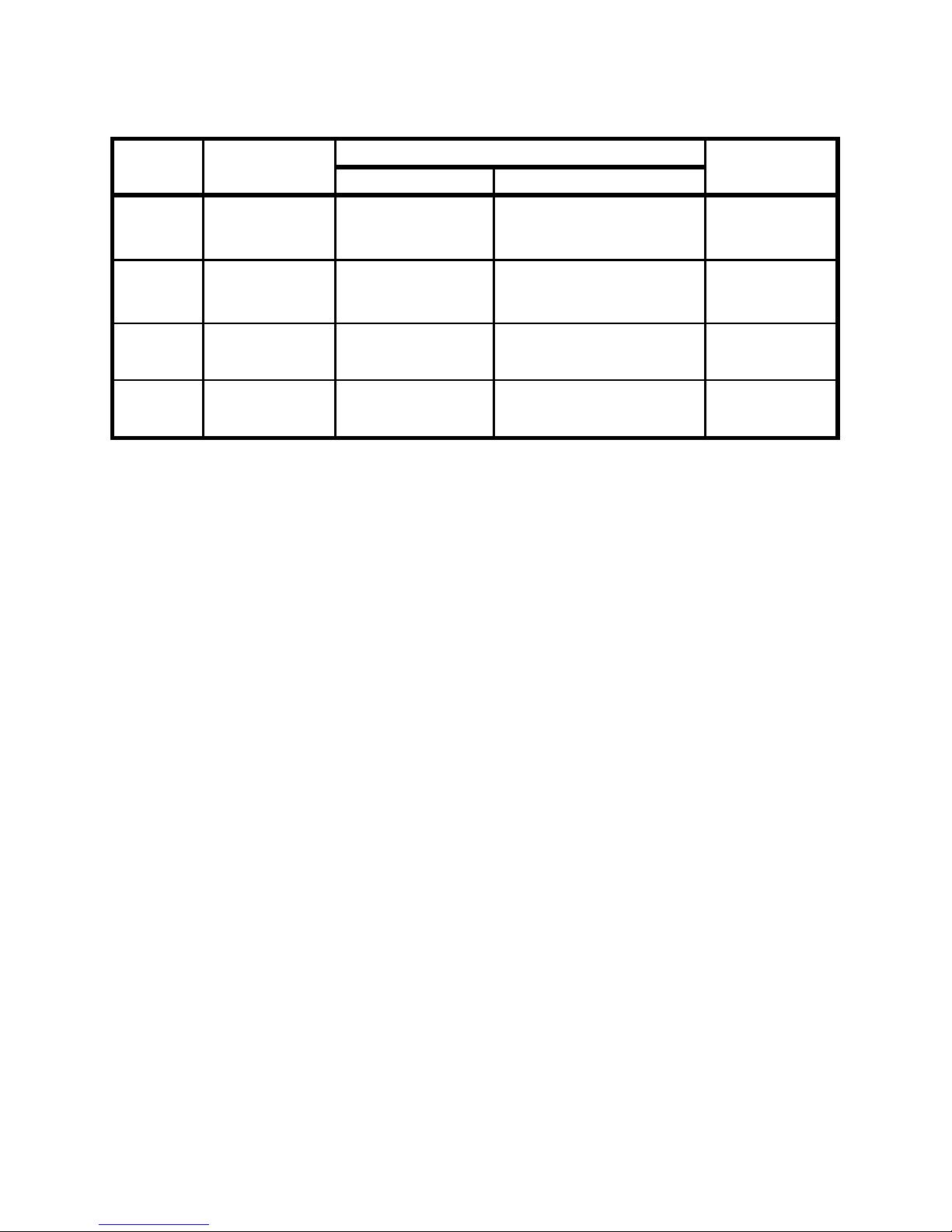
Mode l 8 79:
Resistance (Parallel mode)
Test Frequency: 100 / 120 Hz
Range
Maximum
Display
Accuracy
Specified Note
@100 Hz
@120Hz
10MΩ 9.999MΩ
2.0%+8 *3 2.0%+8 *3 After open ca l.
2000KΩ 1999.9KΩ
0.5%+5 0.5%+5 After ope n cal.
200KΩ
199.99KΩ
0.5%+3 0.5%+3 -
20KΩ 19.999KΩ
0.5%+3 0.5%+3 -
2000Ω 1999.9Ω
0.5%+3 0.5%+3 -
200Ω
199.99Ω
0.8%+5 0.8%+5 After short cal.
20Ω
19.999Ω
1.2%+40 1.2%+40 After short cal.
Test Frequency: 1K / 10K Hz
Range
Maximum
Display
Accuracy
Specified Note
@1K Hz
@10KHz
10 MΩ
9.999MΩ
2.0%+8 * 3 3.5%+10 * 3 After ope n cal.
2000 KΩ 1999.9KΩ
0.5%+5 2.0%+10 After open cal.
200 KΩ 199.99KΩ
0.5%+3 1.5%+5 -
20 KΩ
19.999KΩ
0.5%+3 1.5%+5 -
2000 Ω
1999.9 Ω
0.5%+3 1.5%+5 -
200 Ω 199.99 Ω
0.8%+5 2.0%+10 Aft e r short cal.
20 Ω 19.999 Ω
1.2%+40 2.5%+200 After short c al.
Notes:
1.
This specification is based on the measurement performed at the test socket.
2.
DUT (Device Under Test) & Test leads be properly s hie lded to GUARD if
necessary.
3.
This specification is based on battery operation.
Page 22

21
Capacitance (Parallel mode)
Test Frequency: 100 / 120 Hz
Range Maximum
Display
Accuracy
Spec. Note
Capacitance
DF
10mF
19.99mF *5
3.0%+5
(DF<0.1)
10%+100/Cx+5
(DF<0.1)
After short c al.
1000μF
1999.9μF*6
1.0%+5
(DF<0.1)
2%+100/Cx+5
(DF<0.1)
After short c al.
200μF
199.99μF
0.7%+3
DF<0.5
0.7%+100/Cx+5
(DF<0.5)
-
20μF 19.999μF 0.7%+3
(DF<0.5)
0.7%+100/Cx+5
(DF<0.5)
-
2000nF
1999.9nF
0.7%+3
(DF<0.5)
0.7%+100/Cx+5
(DF<0.5)
-
200nF
199.99nF
0.7%+5
(DF<0.5)
0.7%+100/Cx+5
(DF<0.5)
After ope n cal.
20nF
19.999nF
1.0%+5
(DF<0.1)
2%+100/Cx+5
(DF<0.1)
After ope n cal.
Test Frequency: 1 KHz
Range
Maximum
Display
Accuracy
Spec. Note
Capacitance
DF
1mF
1.999mF *5
3.0%+5
(DF<0.1)
10%+100/Cx+5
(DF<0.1)
After short c al.
200μF
199.99μF
1.0%+5
(DF<0.1)
2.0%+100/Cx+5
(DF<0.1)
After short c al.
20μF
19.999μF
0.7%+3
(DF<0.5)
0.7%+100/Cx+5
(DF<0.5)
-
2000nF
1999.9nF
0.7%+3
(DF<0.5)
0.7%+100/Cx+5
(DF<0.5)
-
200nF 199.99nF 0.7%+3
(DF<0.5)
0.7%+100/Cx+5
(DF<0.5)
-
20nF 19.999nF 0.7%+5
(DF<0.5)
0.7%+100/Cx+5
(DF<0.5)
After ope n cal.
2000pF 1999.9pF 1.0%+5
(DF<0.1)
2.0%+100/Cx+5
(DF<0.1)
After ope n cal.
Page 23

22
Test Frequency: 10 KHz
Range
Maximum
Display
Accuracy
Spec. Note
Capacitance
DF
50μF 50.0μF 3.0%+8
(DF<0.1)
12%+100/Cx+10
(DF<0.1)
After short c al.
20μF 19.999μF 3.0%+6
(DF<0.2)
5.0%+100/Cx+8
(DF<0.2)
After short c al.
2000nF 1999.9nF 1.5%+5
(DF<0.5)
1.5%+100/Cx+6
(DF<0.5)
-
200nF 199.99nF 1.5%+5
(DF<0.5)
1.5%+100/Cx+6
(DF<0.5)
-
20nF 19.999nF 1.5%+5
(DF<0.5)
1.5%+100/Cx+6
(DF<0.5)
-
2000pF 1999.9pF 2.0%+6
(DF<0.5)
3.0%+100/Cx+6
(DF<0.5)
After ope n cal.
200pF 199.99pF 3.0%+8
(DF<0.1)
5.0%+100/Cx+8
(DF<0.1)
After ope n cal.
Notes:
1.
Q Value is the reciprocal of DF.
2.
This specification is based on the measurement performed at the test socket.
3.
DUT & Tes t leads should be properly shielded to GUARD if necessar y.
4.
Cx=Counts of displayed C value, e.g. C=88. 88μF then Cx=8888.
5.
This reading can be extended to 1999 MAX display with accuracy not
specified.
6.
This reading can be extended to 19999 MAX display with accuracy not
specified.
Page 24

23
Inductance (Series mode)
Test Frequency: 100 / 120Hz
Range
Maximum
Display
Accuracy (DF<0.5)
Spec. Note
Inductance
DF
1000H 999.9H 1.0%+(Lx
/10000) %+5
2%+100/Lx+5 After open cal.
200H 199.99H 0.7%+(Lx
/10000)%+5
1.2%+100/Lx+5 -
20H 19.999H 0.7%+(Lx
/10000)%+5
1.2%+100/Lx+5 -
2000m 1999.9mH 0.7%+(Lx
/10000)%+5
1.2%+100/Lx+5 -
200mH 199.99mH 1.0%+(Lx
/10000)%+5
3%+100/Lx+5 After short ca l.
20mH 19.999mH 2.0%+(Lx
/10000)%+5
10%+100/Lx+5 After short c al.
Test Frequency: 1 KHz
Range
Maximum
Display
Accuracy (DF<0.5)
Spec. Note
Inductance
DF
100H 99.99H 1.0%+(Lx
/10000) %+5
2.0%+100/Lx+5 After open cal.
20H 19.999H 0.7%+(Lx
/10000)%+5
1.2%+100/Lx+5 -
2000mH 1999.9mH 0.7%+(Lx
/10000)%+5
1.2%+100/Lx+5 -
200mH 199.99mH 0.7%+(Lx
/10000)%+5
1.2%+100/Lx+5 -
20mH 19.999mH 1.0%+(Lx
/10000)%+5
3.0%+100/Lx+5 After short cal.
2000µH 1999.9µH
2.0%+
(Lx/10000)%+5
10%+100/Lx+5 After short c al.
Page 25
24
Test Frequency: 10 KHz
Range
Maximum
Display
Accuracy (DF<0.5)
Spec. Note
Inductance
DF
1000mH 999.9mH 2.0%+(Lx
/10000)%+ 8
2.0%+100/Lx+10 -
200mH 199.99mH 1.5%+(Lx
/10000)%+8
2.0%+100/Lx+10 -
20mH 19.999mH 1.5%+(Lx
/10000)%+10
3.0 %+100/Lx+15 -
2000µH 1999.9µH
2.0%+(Lx
/10000)%+10
8.0 %+100/Lx+20
After short c al.
Notes:
1.
1.Q Value is the reciprocal of DF.
2.
This specification is based on the measurement performed at the
test socket.
3.
DUT & Test leads shall be properly shielded to GUARD if
necessary.
4. Lx=counts of displayed L value, e.g. L=88.88H, then Lx=8888.
Page 26

25
Model 878A:
Resistance (parallel mode)
Test Frequency: 120Hz / 1KHz
Range Maximum
Display
Accuracy
Specified Note
@120 Hz
@1KHz
10MΩ 9.999MΩ
2.0%+8 *3 2.0%+8 *3 After open cal.
2000KΩ
1999.9KΩ
0.5%+5
0.5%+5
After ope n cal.
200KΩ 199.99KΩ
0.5%+3
0.5%+3
-
20KΩ 19.999KΩ
0.5%+3 0.5%+3 -
2000Ω
1999.9Ω
0.5%+3
0.5%+3
-
200Ω 199.99Ω
0.8%+5
0.8%+5
After short c al.
20Ω 19.999Ω
1.2%+40 1.2%+40 After short ca l.
Notes:
1.
This specification is based on the measurement performed at the test socket.
2.
DUT (Device Under Test) & Test leads be properly shielded to GUARD i f
necessary.
3.
This specification is based on battery operation.
Capacitance (parallel mode)
Test Frequency: 120 Hz
Range Maximum
Display
Accuracy Spec. Note
Capacitance
DF
10mF
19.99mF *5
3.0%+5
(DF<0.1)
10%+100/Cx+5
(DF<0.1)
After short c al.
1000μF 1999.9μF*6
1.0%+5
(DF<0.1)
2%+100/Cx+5
(DF<0.1)
After short c al.
200μF 199.99μF 0.7%+3
DF<0.5
0.7%+100/Cx+5
(DF<0.5)
-
20μF
19.999μF
0.7%+3
(DF<0.5)
0.7%+100/Cx+5
(DF<0.5)
-
2000nF
1999.9nF
0.7%+3
(DF<0.5)
0.7%+100/Cx+5
(DF<0.5)
-
200nF
199.99nF
0.7%+5
(DF<0.5)
0.7%+100/Cx+5
(DF<0.5)
After open cal.
20nF
19.999nF
1.0%+5
(DF<0.1)
2%+100/Cx+5
(DF<0.1)
After ope n cal.
Page 27

26
Test Frequency: 1 KHz
Range
Maximum
Display
Accuracy
Spec. Note
Capacitance
DF
1mF
1.999mF *5
3.0%+5
(DF<0.1)
10%+100/Cx+5
(DF<0.1)
After short c al.
200μF 199.99μF 1.0%+5
(DF<0.1)
2.0%+100/Cx+5
(DF<0.1)
After short c al.
20μF 19.999μF 0.7%+3
(DF<0.5)
0.7%+100/Cx+5
(DF<0.5)
-
2000nF
1999.9nF
0.7%+3
(DF<0.5)
0.7%+100/Cx+5
(DF<0.5)
-
200nF
199.99nF
0.7%+3
(DF<0.5)
0.7%+100/Cx+5
(DF<0.5)
-
20nF
19.999nF
0.7%+5
(DF<0.5)
0.7%+100/Cx+5
(DF<0.5)
After ope n cal.
2000pF
1999.9pF
1.0%+5
(DF<0.1)
2.0%+100/Cx+5
(DF<0.1)
After ope n cal.
Notes:
1.
Q Value is the reciprocal of DF.
2.
This specification is based on the measurement performed at the test socket.
3.
DUT & Tes t leads should be properly shielded to GUARD if necessary.
4.
Cx=Counts of displayed C value, e.g. C=88. 88μF then Cx=8888.
5.
This reading can be extended to 1999 MAX display with accuracy not
specified.
6.
This reading can be extended to 19999 MAX display with accuracy not
specified.
NOTE: Specifications and inf o r m ation are s ubject t o change withou t
notice. Please visit
www.bkprecision.com for the most current product
information.
Page 28

27
Inductance (Series mode)
Test Frequency: 120Hz
Range Maximum
Display
Accuracy (DF<0.5) Spec. Note
Inductance
DF
1000H
999.9H
1.0%+(Lx
/10000) %+5
2%+100/Lx+5
After ope n cal.
200H 199.99H 0.7%+(Lx
/10000)%+5
1.2%+100/Lx+5 -
20H 19.999H 0.7%+(Lx
/10000)%+5
1.2%+100/Lx+5 -
2000m
1999.9mH
0.7%+(Lx
/10000)%+5
1.2%+100/Lx+5
-
200mH
199.99mH
1.0%+(Lx
/10000)%+5
3%+100/Lx+5
After short cal.
20mH
19.999mH
2.0%+(Lx
/10000)%+5
10%+100/Lx+5
After short c al.
Test Frequency: 1 KHz
Range
Maximum
Display
Accuracy (DF<0.5)
Spec. Note
Inductance
DF
100H
99.99H
1.0%+(Lx
/10000) %+5
2.0%+100/Lx+5
After ope n cal.
20H
19.999H
0.7%+(Lx
/10000)%+5
1.2%+100/Lx+5
-
2000mH
1999.9mH
0.7%+(Lx
/10000)%+5
1.2%+100/Lx+5
-
200mH
199.99mH
0.7%+(Lx
/10000)%+5
1.2%+100/Lx+5
-
20mH 19.999mH 1.0%+(Lx
/10000)%+5
3.0%+100/Lx+5 After s hort cal.
2000µH 1999.9µH
2.0%+
(Lx/10000)%+5
10%+100/Lx+5 After short ca l.
Notes:
1.
Q Va lue is the reciprocal of DF.
2.
This specification is based on the measurement performed at the
test socket.
3.
DUT & Test leads shall be properly shielded to GUARD if
necessary.
4. Lx=counts of displayed L value, e.g. L=88.88H, then Lx=8888.
Page 29

28
MAINTENANCE
WARNING
To avoid electrical shock, do not perform any service unless you are
qualified to do so.
SERVICE
If the instrument fails to operate, to check battery and test leads, and
replaces them if necessary. If the instrument still can’t work, double
check ope rating procedure as desc r i bed in thi s instructio n ma nual. When
servicing, use sp ecified replacement par ts only. The meter mu st be
comp letely turned o ff wh ile replacing either the fuse or battery.
Battery Replacement
The meter is powe red a single 9V battery, with NEDA1604, JIS006P,
IEC6F22 carbon-zinc or alka l ine battery. Replace bat tery if the low
battery sign (
) is displayed and flashing. Use the following
procedures to replace the battery:
1.
Loosen screws with suitable screwdriver and remove
battery cover as
Figure-9
.
2.
Replace the degraded battery with a new battery.
Figure-9. Battery Replacement.
Page 30

29
Fuse Replacement
The meter can sel f-detect if its input protective fuse is either open or
damaged. In this case, the LCD will display the symbol "FUSE" and an
audible beep will sounds continuously, warning the user to replace the
damaged fuse to maintain the accuracy of measurement. While
replacing t he fuse, the power of the meter must be completely shut off.
1.
Loos en screws with suitable screwdriver and remove battery cover
as
Figure-9
.
2.
Loosen screws with sui table sc re wdriver a n d remove b ot tom cover
as
Figure-10
.
3.
Replace the damaged fuse wit h specified one.
Figure-10. Fuse Replacement
Page 31

30
Cleaning the Meter
WARNING
To avoid electrical shock or damaging the meter, never get water inside
the case.
Before c lean ing this meter, make sure the power is switched in
OFF position and remove external DC adaptor. To clean the
meter, wipe t he di rty pa rts with ga uze or soft c loth soaked with
diluted neutral detergent. Do not get too wet to prevent the
detergent from penetrating into inside parts and causing
damages. After cleaning, make sure the instrument is dried
completely before using.
Page 32

31
Limited One-Year Warranty
B&K Precision Corp. warrants to the original purchaser that its products
and the component pa rts thereof , will be free from def ects in
workmanship and materials for a period of one year from date of
purchase.
B&K Precision Corp. will, without charge, repair or replace, at its
option, defective product or component parts. Returned product must be
acc o mpanied by proof of the purchase date in the form of a sales receipt.
To obtain warranty coverag e in the U.S.A., this product m us t be
registered by completing a warranty registration form on
www.bkprecision.com within fifteen (15) days of purchase.
Exclusions: This warranty does not apply in the event of misuse or
abuse of the product or as a resul t of unautho rize d al terations or
repairs. The warra nty is void if the seria l number is altered, defaced
or remo ved.
B&K Precision Corp. shall not be liable for any consequential damages,
including without limitation damages resulting from loss of use. S om e
states do not allow limita tions of incidental or cons equential damages .
So the above lim itation or exc lusion may not ap ply to you.
This warranty gives you specific rights and you may have other rights,
which vary from state-to-state.
B&K Precision Corp.
22820 Savi Ranch Parkway
Yorba Linda, CA 92887
www.bkprecision.com
714-921-9095
Page 33

32
Service Information
Warranty Service: Please return the product in the original packaging
with proof of purchase to the address below. Clearly state in writing the
performance problem and return any leads, probes, connectors and
acc essories that you are usi ng with th e devic e.
Non-Warranty Service: Return the product in the origi nal packaging to
the address below. Clear ly state in writing the performance problem and
return any leads, probes, connectors and accessories that you are using
with the device. Customers not on open account must include payment
in the form of a money order or credit card. For the most current rep ai r
charges please visit
www.bkprecision.com and click on “service/repair”.
Return all merchandise to B&K Precision Corp. with pre-paid shipping.
The flat-rate repair charge for Non-Warranty Service does not include
return shipping. Return shipping to locations in North American is
included for Warranty Service. For overnight shipments and non-North
American shipping fees plea se contact B&K Precisi o n Corp.
B&K Precision Corp.
22820 Savi Ranch Parkway
Yorba Linda, CA 92887
www.bkprecision.com
714-921-9095
Include with the returned instrument your complete return
shipping address, contact name, phone number and description of
problem.
Page 34

33
22820 Savi Ranch Parkway
Yorba Linda, California 92887
www.bkprecision.com
©2006 B&K Precision Corporation
Printed in 481-524-9-001
 Loading...