

Page 1

Instruction Manual
MANUAL DE INSTRUCCIÓNES
Model 875B Digital LCR Meter
Medidor Digital LCR Modelo 875B
Page 2

TABLE OF CONTENTS
ONE: INTRODUCTION
1.1 Inspection
1.2 Included Items
1.3 Unit Descriptions
TWO: OPTERATION AND MEASUREMENT
2.1 Warning
2.2 Cautions
2.3 875B Zero Adjustment and
Impedance Measurement
2.3.1 Zero Adjustment and Capacitance
Measurement
2.3.2 Zero Adjustment and Inductance
Measurement
2.3.3 Resistance Measurement
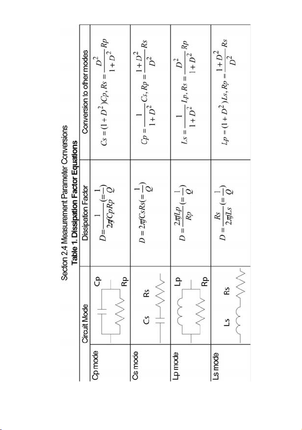
2.4 Measurement Parameter Conversions
THREE: SPECIFICATIONS
3.1 Power Source
3.2 Instrument Specifications
3.3 General Specifications
FOUR: USEER MAINTENANCE
4.1 Battery Replacement
4.2 In Case of Difficulties
FIVE: SERVICE INFORMATION
SPANISH MANUAL
1
Page 3

ONE: INTRODUCTION
Congratulations! You ha ve just pur chased some of t he mo st
advanced hand-held digital LCR meter available. This meter is
sure to provide years of reliable service.
The 875B is designed to m easure the param eters of an
impedance e lement w ith high accuracy and speed.
Measurements o f inductance, capacita nce, resistance
(equivalent series resistance) and dissipation factor are provided
for over a broad band of ra nges. In ad dition, you’ll find that it is
ideal for testing SMD ty pe compon ents. P lus, the instrument
offers advanced features, such as the ability to perform precision
measurements of very low resistan ces w ith t he 2 o hm and
20ohm r anges, and id eal for mea suring indu ctances w ith the
200μH t o 200H ranges, a long w ith the un ique drop- proof
construction, comb ine to make the unit the most versatile
handheld LCR meter available today.
With proper care a nd use , the se meters can pro vide y ears of
reliable op eration. Therefore, it is very important t o com pletely
familiarize yourself with the instrument before attempted use.
Please read this manual carefully, paying particular attention to
the safety section.
Inspection
1.1
When y ou unpa ck y our new Meter from it s or iginal p ackaging,
carefully check each item for damage that may have occurred in
shipment. I f any thing is d amaged or missin g, t ake the ent ire
instrument, including the box and pa cking mat erials, back to the
distributor from w hom it w as pur chased, w here t hey w ill e ither
replace the missing or damaged item or the entire instrument.
Included Items
1.2
Meter Test Leads (1 pair) Battery
1
Page 4

1.3 Unit Description
Please use the dr awings of the 87 5B, in co njunction with the
following descriptions of the con trols and co nnections to help
familiarize you with the unit:
(1) Liquid Crystal Display : Indicates the value of capacitance
(2) LCR/D Mode Switch : Selects either LCR or Dissipation
(3) Function/Range Switch : Selects the function and ra nge for
(4) Common Terminal Slot : The ne gative ( common) te st
(5) Positive Terminal Slot : The positive (high) test connector
(6) Common Terminal Jack : The negative (low) banana jack for
(7) Positive Terminal Jack : The positive (high) banana jack for
(8) Battery Compartment : Access for the battery.
(9) Tilt Stand : Used to hold the instrument at an
(10) Zero Adjust : Control used to zero the display.
(11) Power Switch : Turns power to t he in strument on
connected to the test inputs.
Factor measurement mode.
the desired measurement.
connector for all measurements.
for all measurements.
measurements r equiring t he us e
of te st leads.
measurements requiring the use
of te st leads.
angle on a level surface, or w hen
reversed to han g it from a
projection.
and off.
2
Page 5

TWO: OPERATION AND MEASUREMENT
Warning
2.1
Electricity can cause severe injur ies or even d eath, sometimes
even with relatively low voltages or currents.
Therefore it is vitally important that any electronic instruments such
as these meters be totally understood before use.
Please do not use this instrument, or any other piece of electrical
or electr onic test e quipment, w ithout f irst th oroughly familiarizin g
yourself with its correct operation and use.
Cautions
2.2
(1) To obtain accurate impedance values, perform zero
adjustment before measurements.
(2) Attempted measurement of charged capacitors will overload
the instrument.
(3) If a dead or partially discharged battery is left in the instrument
for an ext ended period, da mage to the unit could result from
battery lea kage. Therefore it is important t o rep lace a
discharged battery prompt ly. Ple ase dispo se o f the u sed
battery in a proper manner. Additionally, if t he instrument will
not be u sed for an extend ed p eriod, a lways remove the
battery from the unit and store it separately.
(4) Do not use solvents or aromatic hy drocarbons to cle an the
instrument, or the plastic case may be damaged. If cleaning is
necessary, use only a mild solution of warm water and soap.
(5) Capacitors are manufactured to operate under certain
conditions. Since the meter
different conditions than of the manufacturer, the values
might not be identical. This is not
the method of test. Therefore, if this is the case, check
the capacitor’s dissipation factor (≦0.1) and whether the
test was conducted in series or parallel mode (ref.
Section 3.6). Use the equations to convert between the
modes. At this point, one should obtain a value to that
test a capacitor under
may
due to meter error, just
3
Page 6

stated on the capacitor.
(6) To ascertain if the meter is accurate, please use a
standard capacitor that states test conditions.
875B Zero Adjustments and Impedance Measurements
2.3
IMPORTANT INFORMATION:
1. As an added feature, the 875B has +/- offsets. The +/-offsets
allow for measurements when the LCD is not at zero. The +/offsets are applicable to components that are measured in the
following mode s: capacitor para llel (C p), in ductor series (Ls)
and resistance series (Rs). The +/- o ffsets are no t applicable
for components th at are te sted C s, Lp or Rp. To u se th is
feature, just simply add/subtract the value from the measured
value of a component.
2. For imp edance measurements there are tw o d ifferent test
modes: parallel and series. The se distinct t est modes ob tain
different results. Refer to section 2.4 for conversions.
2.3.1 Zero Adjustment and Capacitance Measurement
(1) Set the power switch to the “on” position.
(2) Set the mode switch to the “LCR” position.
(3) Set the Function/Range switch to the appropriate capacitance
range for the capacitor under test. If the capacitance value is
unknown, select the 200pF range.
NOTE: If test leads will be used in the measurement, have them
plugged in the banana jacks, but not connected.
200pF, 2nF, 20nF, 200nF & 2µF Range (Cp):
Zero Ad justment (Cp Mode)
(4) Set the Capacitance meter to the se lected Capacitance
range.
(5) Using a small, flat-blade screwdriver, slowly turn the “0 Adj”
control to calibrate the display for a zero re ading. Now the
meter is calibrated for these four ranges.
4
Page 7

(6) Set the m eter to p roper capacitance range and go to step
seven to measure capacitance.
20µF, 200µF , 2mF & 20mF (Cs): Range
Zero A djustment (Cs Mode)
(4) Set the capacitance meter to the 2µF Capacitance range.
(5) Using a small, flat-blade screwdriver, slowly turn the “0 Adj”
control to calibrate the display for a zero re ading. Now the
meter is calibrated for these four ranges.
(6) Set the meter to p roper capacitance range a nd g o to step
Capacitance & Dissipation Factor Measurements
seven to measure capacitance.
(7) Discharge the capacitor to be measured.
(8) Insert the capacitor leads into the component test sockets at
the front of the meter. If the capacitor leads are too short, use
the alligator clip leads provided with the instrument to connect
to the capacitor. Be sure to o bserve the proper po larity if t he
capacitor is a polarized type.
(9) Read the capacitance value in the d isplay. If “1---“(a one w ith
the following 3 dig its blanked) is shown (w hich indicates an
over-range reading), move the range switch to the next higher
capacitance. If necess ary
measurement.
(10) To measure the “D issipation Factor” of the capacitor, set the
mode switch to th e “D” po sition, a nd read t he d issipation
factor value in the display.
(11) ESR Fur capacitors
“Equivalent Series Resistance” is ty pically much larger than
the actual “ohmic” series resistance of the wire leads and foils
that ar e phy sically in series w ith the heart of a ca pacitor,
because ESR includes also the effect of dielectric loss. SR is
related to D by the formu la E SR=Rs=D/wCs (w here w
represents “ome ga” =2 p i times frequency). In 20 mf ra nge,
the d issipation fa ctor can be obtained by the formu lary D=
, perform ze ro ad justment b efore
5
Page 8

WCsRs w here C s in th e mea sured va lue and R s is
measured by 2Ω r ange.
NOTE: To avoid possible damage to the instrument, discharge all
capacitors before attemp ting to measure the va lue or
dissipation factor.
2.3.2 Zero Adjustment and Inductance Measurements
200µH, 2mH, 20m H, 200mH range (Ls):
Zero Adjustment & Measurements
(1) Set the power switch to the “on” position.
(2) Set the mode switch to the “LCR” position.
(3) Set the Function/Range switch to the appropriate range for the
inductor under test. If the inductance value is unknown, select
the 200µH range.
NOTE: Each range must have zero adjustment performed.
(4) Using a short piece of w ire, such as a paper clip, temporarily
connect the po sitive and nega tive m easurement terminals
together. A lternatively, if t he clip leads w ill b e u sed for the
measurement plug them into the banana jacks and connect
the clips together.
(5) Use a small, flat-blade screwdriver and slowly turn the “ 0 Adj”
control to calibrate the display for a zero reading. Remove the
calibration short.
(6) Insert the inductor leads into the component test sockets at the
front of th e meter. If the leads are too short, u se the alligator
clip leads pro vided w ith the instrum ent to connect t o the
inductor.
(7) Read the inductance value in the display. If “1---“ (a one with
the fo llowing 3 d igits b lanked) is shown, move the ra nge
switch to the next higher range until the over range indication is
gone from the display. Repeat steps 4-7.
6
Page 9

2H, 20H, 200H, range (Lp): Zero Adjustment & Measurements
(1) Set the power switch to “on” position.
(2) Set the mode switch to the “LCR” position.
NOTE: These three ranges (Lp mode) must be zero calibrated at
200mH range.
(3) Set the Function/Range switch to the 200mH range.
(4) Using a short piece of w ire, such as a paper clip, temporarily
connect the po sitive and nega tive m easurement terminals
together. A lternatively, if t he clip leads w ill b e u sed for the
measurement, plug them into t he banana jacks an d connect
the clip together.
(5) Use a small, flat-blade screwdriver and slowly turn the “ 0 Adj”
control to calibrate the display for a zero reading. Remove the
calibration short.
(6) Insert the inductor leads into the component test sockets at the
front of th e meter. If the leads are too short, u se the alligator
clip leads pro vided w ith the instrum ent to connect t o the
inductor.
(7) Read the inductance value in the display. If “1---“ (a one with
the fo llowing 3 d igits b lanked) is shown, move the ra nge
switch to the next higher range until the over range indication is
gone from the display and a value is obtained.
(8) To measure the “ Dissipation Fa ctor” of th e inductor, set the
mode switch to the “D” position, and read the dissipation factor
value in the display.
2.3.3 Resistance Measurements
NOTE: A. The 2, 20, 200, 2K, 20K, 200K, ohm ranges of resistance
needs to be zero adjusted separately.
B. It can not be zero adjusted at 2M and 20M range. There
is always a reading about .120-.140 when input
terminals are shorted to zero adjust, set the range
switch to 200K range and zero adjust.
7
Page 10

(1) Turn unit on.
(2) Set the mode switch to the “LCR” position.
(3) Set the Fun ction/Range switch to the appro priate resista nce
range. If the value of resistance is unknown, select the 2 ohm
range.
(4) Using a short piece of w ire, such as a paper clip, temporarily
connect the po sitive and nega tive m easurement terminals
together. A lternatively, if t he clip leads w ill b e u sed for the
measurement, plug them into t he banana jacks an d connect
the clips together.
(5) Use a small, flat-blade screwdriver and slowly turn the “O A dj”
control to calibrate the display for a zero reading. Remove the
calibration short.
(7) Insert the resistor leads into the component test sockets at the
front of th e meter. If the leads are too short, u se the alligator
clip leads provided with the instrument to connect to resistor.
2.4 Measurement Parameter Conversions
The paramet er va lue for a co mponent mea sured in a parallel
equivalent circuit and tha t value me asured in a series equivalent
circuit may be diff erent fro m ea ch o ther. Th is means t hat the
parallel-measured capacitance (inductance) of any given capacitor
(inductor) w ill no t b e equa l t o the ser ies-measured capacitance
(inductance) unless
equals zero. The equat ions in t he tab le be low sh ow the
relationship be tween the para llel- a nd the serie s- m easured
parameters of any given components:
E.G.1: With a m easurement fre quency of 1KH z, a para llel mo de
capacitance of 1000pF with a dissipation factor of 0.5 is equal to a
the dissipation factor of the capacitor (inductor)
Dissipation Factor Equations
(See table 1)
8
Page 11

series mode capacitance of 1250pF.
Cs=( 1 + D × D ) × Cp
Cs=( 1 + 0.5 × 0.5 ) × 1000pF
Cs=1250pF
E.G.2: With a me asurement frequ ency of 1K Hz, a series inductance of
1000uH with a dissipation factor of 0.5 has a series resistance of
3.14 ohms.
Rs=2 × 3.14 × f × Ls × D
Rs=2 × 3.14 × 1K × 1m × 0.5
However, a t a ny given mea surement frequency, the d issipation
factor of a component is the same for both parallel equivalent and
series equivalent circuits.
Additionally, the recipro cal of the dissipation fa ctor (1/D) is
equivalent to the quality factor (Q).
THREE: SPECIFICATIONS
3.1
Power Source
Battery Type: 006P 9V battery.
Power Consumption’s: 155mW
NOTE: Specifications and information are subject to
change without notice. Please visit www.bkprecision.com
the most current product information.
Rs=3.14
for
9
Page 12
10
Page 13

3.2 INSTRUMENT SPECIFICATIONS
Electrical Specifications
(See tables 2)
NOTE: (1) The test leads should be as short as possible to
minimize the measurement error.
(2) For best accuracy, zero adjustment should be
performed appropriately before testing.
Table 2.
CAPACITANC E
Range *Accuracy Resolution Test Condition
200pF 0.1pF
2nF 1pF
20nF 10pF
200nF 100pF
1%+2
Parallel Mode
1KHz, 0.5Vrms
2µF 1000pF
20µF 0.01µF Series Mode 120Hz, 1mArms
200µF
2mF 1µF
20mF
2%+10
0.1µfF
10µfF
Series Mode
120Hz, 10mArms
*Accuracy is ± ( % of reading+number of digits ) When D≦0.1
DISIPATION FACTOR
Range Accuracy
200pF 2nF≦Cx≦2µF 2µF<Cx≦2mF 20mF
0 ~ 1.999
N.S.
2000
10%1 ++
Cx
2000
20%2 ++
Cx
N.S.
Accuracy is ± ( % of reading+number of digits ).
Cx is capacitance readout in counts.
Accuracy is applied when C is from 20 to 100% of full scale range in series
mode measurements.
Parallel Mode
Dc
1
=
2
fCpRp
π
11
Cp
Rp
Page 14

π
=
Cs Rs
fCsRsDc
2
Series Mode
RESISTANCE
Range Accuracy Resolution Test Condition
2Ω 1%+5 1mΩ 10mArms
20Ω 10mΩ 10mArms
200Ω 100mΩ 1mArms
2KΩ 1Ω 0.1mArms
20KΩ 10Ω 10µArms
200KΩ
2MΩ 1KΩ
20MΩ
Accuracy is ± ( % of reading+number of d igits ) an d is applied from 10 to
100% of full scale range in parallel mode measurements.
In series mode measurements, the compliance voltage (voltage drop on the
device under test) should be less than 0.2 Vrms.
INDUCTANCE
Range Accuracy Resolution Test Condition
200µH 2%+2 0.1µH 10mArms, 1KHz
2mH 1µH 10mArms, 1KHz
20mH 10µH 1mArms, 1KHz
200mH
2H 1mH
20H 10mH
200H
Accuracy is ± ( % of reading+number of digits ) When D≦0.1.
The accuracy is applied from 10 to 100% of full scale range in parallel mode
measurements.
*Ranges for reference only.
1%+2
2%+2
1%+2
Not
Specified*
100Ω
10KΩ
100µH
100mH
Series
Mode
1KHz
Series
Mode
1µArms
Parallel Mode
1KHz, 0.5Vrms
0.1mArms,1KHz
Parallel Mode
120Hz, 0.5Vrms
12
Page 15

DISSIPATION FACTOR
Range Accuracy
Lx≦200mH 200mH<Lx<200H
0 ~ 1.999
10%1 ++
2000
Lx
20%2 ++
2000
Lx
Accuracy is ± ( % of reading+number of digits ).
Lx is inductance readout in counts.
Accuracy is applied when L is from 20 to 100% of full scale range in parallel
mode measurements.
Parallel Mode
Lp
π
2=
fD
L
Rp
Lp
Rp
Series Mode
Rs
D
=
π
2
fLs
L
Ls Rs
NOTE : ALL THE ACCURACY IS GUARANTEED AT TEMPERATURE
OF 15℃ TO 28℃, RELATIVE HUMIDITY TO 80% AND HALF
YEAR CALIBRATION CYCLE.
3.3 GENERIAL SPECIFICATIONS
Power Single 9V 006P Battery
0.5
〞
Display
Low Battery Warning
digital height, 3 1/2 digits liquid crystal
display with “LOBAT” and decimal annunciates
Display will show “LOBAT” in the last 5% of
Battery life
Current Consumption 17.3mA
Temperature
0℃ ~ 40℃, Operating
-20℃ ~ 70℃, Storage
Dimensions 177×88×40mm
Weight 400 gram
Standard Accessories
Test Clips (red & black) 1 pair
Operation Manual 1 piece
Optional Accessories Measurement clip TL-8 for SMD type component
13
Page 16

FOUR: USER MAINTENANCE
Battery Replacement
4.1
When the instrument displays the “LO BAT” ind ication, the battery
must be replaced t o maintain proper operation. Please perform the
following steps to change the battery:
(1) Remove the battery hatch by sliding it towards the bottom of the
instrument.
(2) Unsnap the ba ttery clip from t he o ld battery . Snap the clip in
place on a new battery . Plea se dispose of used batteries in a
proper manner.
(3) Place the new battery in the battery compartment.
(4) Replace the battery hatch by reversin g the pro cedure u sed to
remove it.
In Case of Difficulties
4.2
These meters are designed to be accurate, reliable, and easy-to-use.
However, it is po ssible that y ou may experien ce d ifficulties dur ing
operation. If there appears t o be any kind of problem during use of
the instrument, please perform the following steps to help determine
the source:
(1) Reread the operating instructions. It is very easy to inadvertently
make mistakes in operating procedure.
(2) Inspect and check the continuity of the test leads. The instrument
will not function properly with broken test leads.
(3) Remove and te st t he battery . The in strument w ill not fu nction
properly with a discharged battery.
If the proceeding three steps fail to resolve the problem, please refer
to the “S ervice I nformation” section or con tact y our nearest
distributor.
NOTE: ATTEMPTED REPAIR, MODIFICAT IONS, OR TAM PERING BY
UNAUTHORIZED PERSONNELWILL VOID THE WARRANTTY.
14
Page 17

Limited Three-Year Warranty
B&K Precision Corp. warrants to the original purchaser that its
products and the component parts thereof, will be free from
defects in workmanship and materials for a period of three
years from date of purchase.
B&K Precision Corp. will, without charge, repair or replace, at
its option, defective product or component parts. Returned
product must be accompanied by proof of the purchase date in
the form of a sales receipt.
To obtain warranty coverage in the U.S.A., this product must
be registered by completing a warranty registration form on
www.bkprecision.com
Exclusions: This warranty does not apply in the event of
misuse or abuse of the product or as a result of unauthorized
alterations or repairs. The warranty is void if the serial number
is altered, defaced or removed.
B&K Precision Corp. shall not be liable for any consequential
damages, including without limitation damages resulting from
loss of use. Some states do not allow limitations of incidental
or consequential damages. So the above limitation or exclusion
may not apply to you.
This warranty gives you specific rights and you may have other
rights, which vary from state-to-state.
B&K Precision Corp.
22820 Savi Ranch Parkway
Yorba Linda, CA 92887
www.bkprecision.com
714-921-9095
within fifteen (15) days of purchase.
15
Page 18

Service Information
Warranty Service: Please return the product in the original
packaging with proof of purchase to the address below. Clearly
state in writing the performance problem and return any leads,
probes, connectors and accessories that you are using with the
device.
Non-Warranty Service: Return the product in the original
packaging to the address below. Clearly state in writing the
performance problem and return any leads, probes, connectors
and accessories that you are using with the device. Customers
not on open account must include payment in the form of a
money order or credit card. For the most current repair charges
please visit
“service/repair”.
Return all merchandise to B&K Precision Corp. with pre-paid
shipping. The flat-rate repair charge for Non-Warranty Service
does not include return shipping. Return shipping to locations
in North American is included for Warranty Service. For
overnight shipments and non-North American shipping fees
please contact B&K Precision Corp.
B&K Precision Corp.
22820 Savi Ranch Parkway
Yorba Linda, CA 92887
www.bkprecision.com
714-921-9095
Include with the returned instrument your complete return
shipping address, contact name, phone number and description
of problem.
www.bkprecision.com
and click on
16
Page 19

MANUAL DE INSTRUCCIÓNES
Medidor Digital LCR Modelo 875B
Page 20

INDICE
UNO: INTRODUCCION
1.1 Inspección
1.2 P
artes incluidas
1.3 Descripción
DOS: OPERACIÓN Y MEDICIONES
2.1 Advertencia
2.2 P
recauciones
2.3 Ajuste de cero
impedancia
2.3.1Ajuste de cero y medición de
capacitancia
2.3.2 Ajuste de cero y medición de
inductancia
2.3.3 Medición de resistencia
2.4 Conversiones de parámetros de
medición
TRES: 3.1 Fuente de poder
3.2 Es
pecificaciones del Instrumento
pecificaciones Generales
3.3 Es
CUATRO: MANTENIMIENTO DEL USUARIO
4.1 Reemplazo de batería
4.2 En caso de dif
CINCO: INFORMACION SOBRE SERVICIO
de la unidad
y medición de
icultades
18
Page 21

UNO: INTRODUCCION
¡Felicidades! Ha adquirido Ud. uno de los medidores portátiles
digitales LCR
de servicio confiable.
El 875B está diseñado para medir los parámetros de un elemento de
i
mpedancia con gran precisión y velocidad. Mide inductancia,
capacitancia, resistencia (en serie) y factor de disipación con un rango
amplio de valores. Además, es ideal para probar componentes del tipo
SMD. El instrumento ofrece características avanzadas, como la
capacidad de medir resistencias muy bajas en los rangos de 2 y 20
ohms, y inductancias en los rangos de 200µH a 200H; además, su
construcción única a prueba de caídas hacen al 875B el instrumento
portátil más versátil de los disponibles actualmente.
Con el uso y atención cuidadosos, este medidor puede brindar años de
servicio conf
completamente con él antes de usarlo. Lea por favor con cuidado este
manual, con atención particular a la sección de seguridad.
1.1 Inspección
Al sacar el instrumento de su empaque original, revise cada
co
mponente para detectar daños que pudieran haberse causado al
transportarse. En caso de cualquier daño o falta, regrese el instrumento
con su empaque al distribuidor que le vendió el aparato, quien
reemplazará cualquier parte dañada o faltante, o todo el instrumento.
1.2 Partes incluidas
Medidor Plomos de prueba (1 par) Batería
1.3 Descripción de la unidad
Por favor, use los diagramas del 875B junto con la descripción de los
controles e indicadores siguiente para
unidad:
1) Pantalla de c
2) Switch de
más avanzados. Este medidor le brindará de seguro años
iable. Por ello, es muy importante familiarizarse
ayudarlo a familiarizarse con la
ristal líquido : Indica el valor de la capacitancia
conectada a las puntas de prueba
modo LCR/D : Selecciona el modo LCR o de
factor de disipación
19
Page 22

3) Switch de Función/Rango : Selecciona la función y rango
para la medición deseada
4) Ter
minal común : Conector negativo (común) para
todas las mediciones
5) Ter
minal positiva : Conector positivo (alto) para
todas las mediciones
6) Jack de ter
para mediciones que requieren
puntas de prueba
7) Jack de ter
para mediciones que requieren
puntas de prueba
8) Co
9) Soporte inclinable
instrumento a un ángulo respecto a
la superficie, o para colgarlo si se
coloca en posición inversa
10) Ajuste de cero
ceros
11) Switch de encendido
instrumento
DOS: OPERACIÓN Y MEDICION
2.1 Advertencia
Una descarga eléctrica puede causar lesiones severas o incluso
m
corriente. Por tanto es de vital importancia que se entienda
totalmente la operación de cualquier instrumento como éste antes
de usarlo, y se ruega al usuario familiarizarse por completo con la
operación correcta del instrumento.
2.2 Precauciones
1) Para obtener
antes de efectuar mediciones
2) La
instrumento
minal común : Jack tipo banana negativo (bajo)
minal positiva : Jack tipo banana positivo (alto) )
mpartimiento de batería : Acceso a la batería
: Usado para colocar el
: Control para poner la pantalla a
: para encender y apagar el
uerte, en ocasiones con valores relativamente bajos de voltaje o
resultados de impedancia exactos, ajuste el cero
medición de capacitares cargados pueden sobrecargar al
20
Page 23

3) Reemplace cuanto la batería si está muerta o parcialmente
descargada, ya que si la mantiene en el instrumento por un
periodo largo puede dañarlo. Además, si no pretende usar el
instrumento por un tiempo largo, remueva la batería y
almacénela separadamente.
4) No use solventes o hidrocarbonos arom
instrumento, pues podría dañar la cubierta de plástico. Use una
solución suave de agua tibia y jabón si es preciso limpiarlo.
5) Los capacitar
Dado que el medidor puede probar un capacitor bajo condiciones
diferentes, los valores pueden ser distintos. Esto no s debe a error
del instrumento, sino al método de medición. En dichos casos,
verifique el factor de disipación (≤0.1) y si la prueba se efectuó
en modo serie o paralelo (ver sección 3.6). Use las ecuaciones de
conversión entre modos. Con ello, debe obtener el valor
establecido del capacitor.
6) Para ver
que establezca las condiciones de prueba.
2.3 Ajuste de cero y mediciones de impedancia
INFORMACION IMPORTANTE
1. El 875B incluy
permiten la medición ciando el LCD no está en cero. Los
desplazamientos son aplicables para componentes que se miden
en los modos siguientes: Cp (capacitor en paralelo), Ls (inductor
serie), y Rs (resistencia serie). No aplican para mediciones Cs,
Lp o Rp. Para usar dicha característica, simplemente sume o
reste el desplazamiento del valor medido
2. Para
serie. Los modos arrojan resultados diferentes. Refiérase a la
sección 2.4 para las conversiones.
2.3.1 Ajuste de cero y medición de capacitancia
1) Fije el sw
2) Fije el sw
es se fabrican para operar bajo ciertas condiciones.
ificar la exactitud del medidor, use un capacitor estándar
e desplazamientos +/-. Estos desplazamientos
medir impedancias hay dos modos de medición: paralelo y
itch de encendido en la posición “ON”
itch de modo en la posición “LCR”
áticos para limpiar el
21
Page 24

3) Fije el switch de función/rango en el rango de capacitancia
apropiado. Si desconoce el valor del capacitor, seleccione el
rango de 200pF
NOTA: Si usa las puntas de prueba, insértelas en los jacks tipo
banana, pero no las conecte.
Rango 200pF, 2nF, 20nF, 200nF & 2µF (Cp); modo de ajuste de
cero (
modo Cp)
4) +Fije el
5) Rote lenta
6) Fije el
Rango 20µF
cero (modo Cs)
4) Fije el
5) Rote lenta
6) Fije el
Mediciones de capacitancia & Factor de disipación
7) Descargue el
8) Inserte las
9) Lea el
10) Para
11) Resistencia serie equivalente (ESR)
medidor de capacitancia al rango seleccionado
plano para mostrar cero en pantalla. Ahora el medidor queda
calibrado en estos rangos.
plano para mostrar cero en pantalla. Ahora el medidor queda
calibrado en estos rangos.
del medidor. Si sus puntas son muy cortas, use los clips tipo
cocodrilo conectándolos al capacitor. Asegúrese de respetar la
polaridad correcta si el capacitor es del tipo polarizado.
(un uno con los 3 siguientes dígitos en blanco, lo cual indica un
rebasamiento), mueva el switch de rango al valor mayor
siguiente. De ser necesario, ajuste el ajuste de cero de nuevo.
lea el valor en pantalla
mente el control “0 Adj” con un desarmador pequeño
rango de capacitancia y siga al paso 7 para la medición
, 200µF, 20nF, 2mF & 20mF (Cs); modo de ajuste de
medidor de capacitancia al rango de 2µF
mente el control “0 Adj” con un desarmador pequeño
rango de capacitancia y siga al paso 7 para la medición
capacitor por medir
puntas del capacitor en los sockets de prueba al frente
valor de la capacitancia en pantalla. Si muestra un “1-“
medir el factor de disipación, fije el switch a la posición D y
.
22
Page 25

La resistencia serie equivalente es usualmente mucho mayor que
la resistencia óhmica serial de las puntas y envoltura de un
capacitor, pues incluye también el efecto de pérdida dieléctrica.
ESR se relaciona con D mediante la fórmula ESR = Rs = D/wCs
(w representa “omega” = 2 pi veces la frecuencia). En el rango
de 20mF, el factor de disipación se obtiene de la fórmula D =
WCsRs donde Cs es el valor medido y Rs se mide en el rango de
2 Ohms.
NOTA: Para evitar daños al instrumento, descargue los
capacitares
2.3.2 Ajuste de cero y medición de inductancia en el rango
1) Fije el switch de encendido en la posición “ON”
2) Fije el sw
3) Fije el sw
apropiado. Si desconoce el valor del inductor, seleccione el
rango de 200µH
NOTA: Debe ajustar el cero en cada rango
4) Use un trozo pequeño de ala
conectar en corto las terminales positiva y
negativa. Si las puntas del clip se usa
insértelas en los jacks banana y conéctelas
juntas.
5) Rote lenta
plano para mostrar cero en pantalla.
Remueva el corto circuito de calibración
6) Inserte las
del medidor. Si sus puntas son muy
cortas, use los clips tipo cocodrilo conectándolos al inductor.
7) Lea el
uno con los 3 siguientes dígitos en blanco, lo cual indica un
rebasamiento), mueva el switch de rango al valor mayor
siguiente. Repita los pasos 4 a 7.
antes de medir el factor de disipación.
200µH, 2mH, 20mH (Ls)
Ajuste de cero & mediciones
itch de modo en la posición “LCR”
itch de función/rango en el rango de inductancia
mente el control “0 Adj” con un desarmador pequeño
puntas del inductor en los sockets de prueba al frente
valor de la inductancia en pantalla. Si muestra un “1-“ (un
mbre, como un clip de papel, para
n para la medición,
23
Page 26

Rangos 2H, 20H (Lp); ajuste de cero & mediciones
1) Fije el sw
2) Fije el sw
NOTA: Estos 3 rangos (modo Lp) deben calibrarse en el rango de
200
mH
3) Fije el sw
200mH
4) Use un trozo pequeño de ala
conectar en corto las terminales positiva y
negativa. Si las puntas del clip se usa
insértelas en los jacks banana y conéctelas
juntas.
5) Rote lenta
plano para mostrar cero en pantalla.
Remueva el corto circuito de calibración
6) Inserte las
del medidor. Si sus puntas son muy cortas, use los clips tipo
cocodrilo conectándolos al inductor.
7) Lea el
uno con los 3 siguientes dígitos en blanco, lo cual indica un
rebasamiento), mueva el switch de rango al valor mayor
siguiente hasta obtener una lectura válida
8) Para
lea el valor en pantalla
2.3.3
NOTA: A: Los rangos de 2,20,200,2K,20K oh
ajustarse por separado
B: Para ajustar a cero los rangos de 2M y 20M fije el switch de
1) Fije el sw
2) Fije el sw
3) Fije el sw
desconoce el valor del resistor, use el rango de 2 Ohms
itch de encendido en la posición “ON”
itch de modo en la posición “LCR”
itch de función/rango en el rango de inductancia de
mbre, como un clip de papel, para
mente el control “0 Adj” con un desarmador pequeño
puntas del inductor en los sockets de prueba al frente
valor de la inductancia en pantalla. Si muestra un “1-“ (un
medir el factor de disipación, fije el switch a la posición D y
Mediciones de resistencia
rango en 200KΩ y efectúe el ajuste
itch de encendido en la posición “ON”
itch de modo en la posición “LCR”
itch de función/rango en el rango apropiado. Si
24
n para la medición,
ms de resistencia deben
Page 27

4) Use un trozo pequeño de alambre, como un clip de papel, para
conectar en corto las terminales positiva y
negativa. Si las puntas del clip se usa
medición,insértelas en los jacks banana y conéctelas juntas.
5) Rote lenta
plano para mostrar cero en pantalla.
Remueva el corto circuito de calibración
Inserte las puntas del resistor en los s
medidor. Si sus puntas son muy
cortas, use los clips tipo cocodrilo conectándolos al resistor
2.4 Conversión de parámetros de medición
El valor de un parámetro medido en un circuito paralelo
puede diferir del medido en un circuito serie equivalente. El valor de
un capacitor o inductor en paralelo no será igual al medido en serie a
menos que el factor de disipación del capacitor o inductor sea cero.
Las ecuaciones de la Tabla 1 relacionan los valores serie y paralelo de
los componentes.
Ejemplo 1: Con una frecuencia de medición de 1KHz, la capacitancia
paralelo Cp de 1000pF con un factor de disipación de 0.5 equivale a la
capacitancia serie
Cs = (1+DxD)xCp = (1+0.5x0.5)x1000pF = 1250pF
Ejemplo 2: Con una frecuencia de medición de 1KHz, una inductancia
serie de 1000µH con un factor de dis
resistencia serie de 3.14 Ohms.
Rs = 2x3.14xfxLsxD = 2x3.14x1Kx1mx0.5 = 3.14 Ohms
Sin embargo, a cualquier frecuencia,
componente es el mismo para los circuitos equivalentes serie y
paralelo. Además, el recíproco del factor de disipación (1/D) es
equivalente al factor de calidad (Q).
mente el control “0 Adj” con un desarmador pequeño
Cs de 1250pF:
n para la
ockets de prueba al frente del
equivalente
ipación de 0.5 tiene una
el factor de disipación de un
25
Page 28

26
Page 29

TRES: ESPECIFICACIONES
3.1 Fuente de poder
Tipo de batería: 006P de 9V
Consumo de batería: 155mW
3.2
Especificaciones del instrumento
Especificaciones eléctricas
NOTA: (1) Las puntas de prueba deben ser tan cortas como sea
posible para minimizar errores del Instrumento
antes de la prueba.
Tabla 2
CAPACITANCIA
* La precisión es ±(% de lectura + número de dígitos) cuando D≤ 0.1
FACTOR DE DISIPACION
(Vea las tablas 2)
(2) Para la mejor precisión, ajuste el cero correctamente
Rango *Precision Resolucion Condicion de prueba
200pF 0.1pF
2nF 1pF
20nF 10pF
200nF 100pF
2µF 1000pF
20µF 0.01µF Modo serial, 120Hz, 1mArms
200µF
2mF 1µF
20mF
Rango Precision
0 ~ 1.999
1%+2
2%+10
200pF 2nF≦Cx≦2µF 2µf<Cx≦2mF 20mF
N.S.
0.1µF
10µF
10%1 ++
2000
Cx
Modo Paralelo
1KHz, 0.5Vrms
Modo serial
120Hz, 10mArms
20%2 ++
2000
Cx
N.S.
27
Page 30

La precisión es ±(% de lectura + número de dígitos)
Cx es la lectura de la capacitancia en cuentas
La precisión se aplica cuando Cx es del 20 al 100% de la escala
completa del rango en modo de medición serial
Modo paralelo
Dc
1
=
2
fCpRp
π
Cp
Rp
Cs Rs
Modo serial
fCsRsDcπ2=
RESISTENCIA
Rango Precision Resolucion Condicion de prueba
2Ω 1%+5 1MΩ 10mArms
20Ω 10MΩ 10mArms
200Ω 100MΩ 1mArms
2KΩ 1Ω 0.1mArms
1%+2
Modo
Serial
1KHz
20KΩ 10Ω 10µArms
200KΩ
2MΩ 1KΩ
20MΩ
2%+2
100Ω
10KΩ
1µArms
Modo Paralelo
1KHz, 0.5Vrms
La precisión es ±(% de lectura + número de dígitos) y se aplica del 10
al 100% de la escala completa en mediciones de modo paralelo. En
modo serial, la caída de voltaje del dispositivo bajo prueba debe ser
menor que 0.2V rms
28
Page 31

INDUCTANCIA
Rango Precision Resolucion Condicion de prueba
200µH 2%+2 0.1µH 10mArms, 1KHz
2mH 1µH 10mArms, 1KHz
20mH 10µH 1mArms, 1KHz
200mH
2H 1mH
20H 10mH
200H
1%+2
Not
Specified*
100µH
100mH
Modo
Serial
Modo Paralelo
120Hz, 0.5Vrms
0.1mArms,1KHz
La precisión es ±(% de lectura + número de dígitos) y se aplica del 10
al 100% de la escala completa en mediciones de modo paralelo
FACTOR DE DISIPACION
Rango Precision
Lx≦200mH 200mH<Lx<200H
0 ~ 1.999
10%1 ++
2000
Lx
20%2 ++
2000
Lx
La precisión es ±(% de lectura + número de dígitos)
Lx es la lectura de la inductancia en cuentas
La precisión se aplica cuando L es del 20 al 100% de la escala
completa del rango en modo de medición paralelo
Modo paralelo
Lp
π
2=
fD
Rp
L
Lp
Rp
Modo serial
Rs
D
=
L
fLs
π
2
Ls Rs
29
Page 32

NOTA: LA PRECISION TOTAL SE GARANTIZA A
TEMPERATURAS DE 15°C a 28°C Y MEDIO AÑO DE CICLO DE
CALIBRACION
3.3
ESPECIFICACIONES GENERALES
Energía Batería sencilla de 9V 006P
Pantalla Altura de 0.5”, digital, 3 ½ LEDS con
Advertencia de
batería baja
Consumo de
corriente
Temperatura 0°C a 40°C en operación. -20°C a 70°C en
Dimensiones 177 x 88 x 40mm
Peso 400 gramos
Accesorios estándar Clips de prueba (rojo&azul) 1 par. Manual de
Accesorios
opcionales
NOTA: Las espec
cambio sin el aviso de B&K Precision Corp. Por favor visite
www.bkprecision.com
información de nuestros productos.
anunciadores “LO BAT” y decimal
Indicador en pantalla muestra “LO BAT” al
5% de vida de la batería
17.2mA
almacenamiento
operación 1 ejemplar
Clip de medición pata componentes tipo SMD
TL-8
ificaciones y la información están conforme a
para las especificaciones más corriente y
30
Page 33

CUATRO: MANTENIMIENTO POR EL USUARIO
4.1 Reemplazo de batería
Cuando el instrumento exhibe “LO BAT” es preciso reemplazar la
batería para
1) Re
2) Libere la
3) Coloque la batería
4) Ree
4.3 En caso de dificultades
Estos medidores se han diseñado para ser precisos, confiables y fáciles
(1) L
(2) Inspecciones y ver
(3) Re
Si estos pasos fallan en resolver el p
NOTA: REPARACIONES O MOFDIFICACIONES NO
una operación adecuada. Siga los pasos siguientes:
mueva el receptáculo de la batería deslizándolo hacia el fondo
del instrumento
batería vieja del sujetador. Sujete con éste la batería
nueva. Por favor, deshágase de la batería vieja de manera
conveniente.
mplace el receptáculo aplicando el procedimiento (1) a la
inversa
de usar. Sin e
durante su operación. En caso de problemas, favor de seguir los
pasos siguientes para ayudar a identificar las causas:
operación. Es muy fácil equivocarse inadvertidamente en los
procedimientos.
las puntas de prueba. El instrumento no funciona correctamente
con puntas rotas.
instrumento no funciona correctamente con una batería
descargada.
“Información sobre servicio” o contacte a su distribuidor más
cercano.
AUTOR
IZADAS O MANIPULACION DEL INSTRUMENTO
POR PERSONAL NO AUTORIZADO INVALIDARAN LA
GARANTIA.
nueva en su compartimiento.
mbargo, es posible que experimente dificultades
ea de nuevo las instrucciones de
ifique la continuidad de
mueva y pruebe la batería. El
roblema, refiérase a la sección
31
Page 34

Garantía Limitada de Tres Anos
B&K Precision Corp. Autorizaciones al comprador original que su
productos y componentes serán libre de defectos por el periodo de tres anos
desde el día en que se compro.
B&K Precision Corp. sin carga, repararemos o sustituir, a nuestra opción,
producto defectivo o componentes. Producto devuelto tiene que ser
acompañado con prueba de la fecha del la compra en la forma de tres recibo
de las ventas.
Para obtener cobertura en los EE.UU., este producto debe ser registrado por
medio de la forma de registro en www.bkprecision.com dentro de quince
(15) días de la compra de este producto.
Exclusiones: Esta garantía no se aplica en el evento de uso en error o
abuso de este producto o el resultado de alteraciones desautorizado o
reparaciones. La garantía es vacía si se altera, se desfigura o se quita el
número de serie.
B&K Precision Corp. no será obligado a dar servicio por danoss
consecuente, incluyendo sin limitaciones a danoss resultando en perdida de
uso. Algtresos estados no permiten limitaciones de daños fortuitos o
consecuentes. Tan la limitación o la exclusión antedicha puede no aplicarse
a usted.
Esta garantía le da ciertos derechos y pueden tener otros derechos, cuales
cambian estado por estado.
B&K Precision Corp.
22820 Savi Ranch Parkway
Yorba Linda, CA 92887
www.bkprecision.com
714-921-9095
32
Page 35

Información de Servicio
Servicio de Garantía: Por favor regrese el producto en el
empaquetado original con prueba de la fecha de la compra a la
dirección debajo. Indique claramente el problema en escritura, incluya
todos los accesorios que se estan usado con el equipo.
Servicio de No Garantía: Por favor regrese el producto en el
empaquetado original con prueba de la fecha de la compra a la
dirección debajo. Indique claramente el problema en escritura, incluya
todos los accesorios que se estan usado con el equipo. Clientes que no
tienen cuentas deben de incluir pago en forma de queque, orden de
dinero, o numero de carta de crédito. Para los precisos mas corriente
visite www.bkprecision.com
Vuelva toda la mercancía a B&K Precision Corp. con el envío pagado
por adelantado. La carga global de la reparación para el servicio de la
No-Garantía no incluye el envío de vuelta. El envío de vuelta a las
localizaciones en norte americano es incluido para el servicio de la
garantía. Para los envíos de noche y el envío del no-Norte los
honorarios americanos satisfacen el contacto B&K Precision Corp.
B&K Precision Corp.
22820 Savi Ranch Parkway
Yorba Linda, CA 92887
www.bkprecision.com
714-921-9095
Incluya con el instrumento la dirección de vuelto para envío,
nombre del contacto, número de teléfono y descripción del
problema.
y oprime “service/repair”.
33
Page 36

The equipment herewith complies with the requirementsents of the EMC Directive 89/
336/EEC and the LVD 73/23/EEC and 93/68/EEC.
Declares that this equipment conforms to the following product specifications:
EMC: CISPR22 : 1993, and EN 55022, 1994, Class B
IEC 1000-4-2 : 1995,and prEN 50082-1, 1994-4KV CD, 8KC AD
IEC 1000-4-3 : 1995, and prEN 50082-1, 1994-3V/m
IEC 1000-4-4 : 1995, and IEC 801-4, 1988-1KV,5/50ns, 5KHz AC power port
IEC 1000-4-5 : 1995, and prEN 50082-1, 1994, Surge-1KV, AC power port
EN 60555-2 : 1987, Harmonics, Class A
EN 60555-3 : 1987, Voltage Fluctuations
Test Report Number : 500-8410-10 (EMI)
500-8409-27 (EMS )
LVD: EN 61010-1/EN 61010-2-031
Test Report Number : 97407-1 ( LVD )
Manufacture’s Name : B&K Precision
Manufacture’s Address : 22820 Savi Ranch Parkway
Yorba Linda, CA 92887.
Modification : The 875B is not designed for use with a AC to DC adaptor, only
Just enough use with 9V 006P Battery. (please cancel item 3.1 on
Page9 of operation manual).
Current Consumption : 10mA average (see manual page14). 17.3mA maxima
Type of Equipment : Hand-held LCR Meter
Model No : 875B
Year of Manufacture 1997
CE97
EC Declaration of Conformity
-Electro Magnetic Compatibility-
-Low V oltage Directive -
Page 37

22820 Savi Ranch Parkway
Yorba Linda, California 92887
U.S.A.
Tel. 714.921.9095
Fax. 714.921.6422
P/N: 480-796-9-001
18
 Loading...