

Page 1

TF7050-M2/TF7025-M2 Setup Manual
FCC Information and Copyright
This equipment has been tested and found to comply with the limits of a Class
B digital device, pursuant to Part 15 of the FCC Rules. These limits are designed
to provide reasonable protection against harmful interference in a residential
installation. This equipment generates, uses, and can radiate radio frequency
energy and, if not installed and used in accordance with the instructions, may
cause harmful interference to radio communications. There is no guarantee
that interference will not occur in a particular installation.
The vendor makes no representations or warranties with respect to the
contents here and specially disclaims any implied warranties of merchantability
or fitness for any purpose. Further the vendor reserves the right to revise this
publication and to make changes to the contents here without obligation to
notify any party beforehand.
Duplication of this publication, in part or in whole, is not allowed without first
obtaining the vendor’s approval in writing.
The content of this user’s manual is subject to be changed without notice and
we will not be responsible for any mistakes found in this user’s manual. All the
brand and product names are trademarks of their respective companies.
Page 2

Table of Contents
Chapter 1: Introduction ........................................ 3
1.1 Before You Start ................................................................................ 3
1.2 Package Checklist............................................................................. 3
1.3 Motherboard Features...................................................................... 4
1.4 Rear Panel Connectors (for TF7050-M2)....................................... 6
1.5 Rear Panel Connectors (for TF7025-M2) ....................................... 7
1.6 Motherboard Layout (for TF7050-M2) .......................................... 8
1.7 Motherboard Layout (for TF7025-M2) .......................................... 9
Chapter 2: Hardware Installation ........................ 10
2.1 Installing Central Processing Unit (CPU)..................................... 10
2.2 FAN Headers.................................................................................... 12
2.3 Installing System Memory .............................................................. 13
2.4 Connectors and Slots....................................................................... 15
Chapter 3: Headers & Jumpers Setup .................. 17
3.1 How to Setup Jumpers .................................................................... 17
3.2 Detail Settings.................................................................................. 17
Chapter 4: RAID Functions .................................. 25
4.1 Operation System............................................................................ 25
4.2 Raid Arrays...................................................................................... 25
4.3 How RAID Works............................................................................. 25
Chapter 5: OverClock Quick Guide ....................... 29
5.1 T-Power Introduction...................................................................... 29
5.2 T-Power BIOS Feature.................................................................... 30
5.3 T-Power Windows Feature ............................................................ 39
Chapter 6: Useful Help ........................................ 48
6.1 Driver Installation Note.................................................................. 48
6.2 Award BIOS Beep Code.................................................................. 49
6.3 Extra Information............................................................................ 49
6.4 Troubleshooting............................................................................... 50
Appendencies: SPEC In Other Language .............. 52
German.................................................................................................................. 52
France .................................................................................................................... 54
Italian ..................................................................................................................... 56
Spanish ................................................................................................................... 58
Portuguese ............................................................................................................ 60
Polish...................................................................................................................... 62
Russian ................................................................................................................... 64
Arabic..................................................................................................................... 66
Japane se ................................................................................................................ 68
Page 3
CHAPTER 1: INTRODUCTION
TF7050-M2/TF7025-M2
1.1 B
EFORE YOU START
Thank you for choosing our product. Before you start installing the
motherboard, please make sure you follow the instructions below:
Prepare a dry and stable working environment with
sufficient lighting.
Always disconnect the computer from power outlet
before operation.
Before you take the motherboard out from anti-static
bag, ground yourself properly by touching any safely
grounded appliance, or use grounded wrist strap to
remove the static charge.
Avoid touching the components on motherboard or the
rear side of the board unless necessary. Hold the board
on the edge, do not try to bend or flex the board.
Do not leave any unfastened small parts inside the
case after installation. Loose parts will cause short
circuits which may damage the equipment.
Keep the computer from dangerous area, such as heat
source, humid air and water.
1.2 PACKAGE CHECKLIST
HDD Cable X 1
Serial ATA Cable X 2
Rear I/O Panel for ATX Case X 1
User’s Manual X 1
Fully Setup Driver CD X 1
FDD Cable X 1 (optional)
USB 2.0 Cable X1 (optional)
S/PDIF out Cable X 1 (optional)
Serial ATA Power Cable X 1 (optional)
Note : The package contents may differ by area or your motherboard version.
3
Page 4
Motherboard Manual
1.3 MOTHERBOARD FEATURES
TF7050- M2 TF7025- M2
Socket AM2
AMD Athlon 64 / Athlon 64 FX / Athlon 64 x2 /
CPU
FSB
Chipset GeForce 7050PV/NF630a GeForce 7025/NF630a
Super I/O
Main
Memory
Graphics
IDE
SATA II
LAN
Sempron processors
AMD 64 Architecture enables 32 and 64 b it
computing
Supports Hyper Transport and Cool=n=Quiet
Supports up to 1 GHz Bandwidth
Support HyperTransport
ITE 8716F
Prov ides the most common ly us ed legac y Super
I/O functionality.
Low Pin Count Interface
En viro nm ent Cont ro l init iati ves,
H/W Mon ito r
Fan Sp eed Contro ller
ITE's "S mart Guard ian " funct ion
DDR2 DIMM Slots x 4
Max Memory Capacity 8GB
Each DIMM supports 256/512MB/1GB/2GB DDR2
Dual Cha nnel Mode DDR 2 me mory modu le
Supports DDR2 400/ 533 / 667 / 800
Register ed D IMM and ECC D IMM is not
supported
Integrated in GeForce 7050PV/NF630a Chipset
Max S hared V id eo Memory is 256 MB
Int eg r at ed IDE Co nt ro lle r
Ultra DMA 33 / 66 / 100 / 133 Bus Master Mode
supports PIO Mode 0~4,
Integrated Serial ATA Controller
Data transfer rates up to 3 Gb/s.
SATA Vers ion 2.0 spe cificat ion co mp liant .
Realtek RTL 8111B / 8101E (optional)
10 / 100 Mb/s / 1Gb/s auto negotiation (Gigabit
bandwidth is for RTL 8111B only)
Half / Full duplex capability
Socket AM2
AMD Athlon 64 / Athlon 64 FX / Athlon 64 x2 /
Sempron processors
AMD 64 Architecture enables 32 and 64 b it
computing
Supports Hyper Transport and Cool=n=Quiet
Supports up to 1 GHz Bandwidth
Support HyperTransport
ITE 8716F
Prov ides t he most commonly used legacy Super
I/O functionality.
Low Pin Count Interface
En viro nm ent Cont ro l init iati ves,
H/W Mon ito r
Fan Sp eed Contro ller
ITE's "S mart Guard ian " funct ion
DDR2 DIMM Slots x 4
Max Memory Capacity 8GB
Each DIMM supports 256/512MB/1GB/2GB DDR2
Dual Cha nnel Mode DDR 2 me mory modu le
Supports DDR2 400/ 533 / 667 / 800
Register ed D IMM and ECC D IMM is not
supported
Integrated in GeForce 7025/NF630a Chipset
Max S hared V id eo Memory is 256 MB
Int eg r at ed IDE Co nt ro lle r
Ultra DMA 33 / 66 / 100 / 133 Bus Master Mode
supports PIO Mode 0~4,
Integrated Serial ATA Controller
Data transfer rates up to 3 Gb/s.
SATA Vers ion 2.0 spe cificat ion co mp liant .
Realtek RTL 8111B / 8101E (optional)
10 / 100 Mb/s / 1Gb/s auto negotiation (Gigabit
bandwidth is for RTL 8111B only)
Half / Full duplex capability
4
Page 5
TF7050-M2/TF7025-M2
TF7050- M2 TF7025- M2
ALC888 (Ver 5.x) / ALC861VD (Ver 6.x)
7.1 channels audio out (Ver 5.x) /
Sound
Slots
On Board
Connector
Back Panel
I/O
Board Size 235 mm(W) x 244 mm(L) 235 mm(W) x 244 mm(L)
Special
Features
OS Support
5.1 channels audio out (Ver 6.x)
High Definition Audio
2 channels audio out for HDMI Audio
PCI slot x2 PCI slot x2
PCI Express x16 slot x1 PCI Express x16 slot x1
PCI Express x 1 slot x1 PCI Express x 1 slot x1
Floppy connecto r x1 Floppy connector x1
Printer Po rt conne ctor x1 Printer Port connector x1
IDE Conn ecto r x1 ID E C onn ector x1
SATA Connector x4 SATA Connector x4
Front Panel Connector x1 Front Panel Connector x1
Front Audio Connector x1 Front Audio Connector x1
CD-in Connector x1 CD-in Connector x1
S/PD IF out connector x1 S/PDIF out connecto r x1
S/PD IF in connector (Optional) x1 S/PD IF in connector (Opt ional) x 1
CPU Fan header x1 CPU Fan header x1
System Fan head er x3 S ystem Fan h ead er x3
CMOS clear header x1 CMOS clear header x1
USB connector x3 USB co nnector x3
Serial port Connector x1 Serial port Connector x1
Power Connector (24pin) x1 Power Conn ector (24pin) x1
Power Connector (4pin) x1 Power Conn ector (4pin) x1
PS/2 Keyboard x 1
PS/2 Mouse x1
S-Video port x1
HDMI po rt x1
VGA port x1
LAN port x1
USB Port x4
Audio Jack (for Ver 5.x) x6
Audio Jack (for Ver 6.x) x3
RAID 0 / 1 / 5 / 0+1 support RAID 0 / 1 / 5 / 0+1 support
Windows 2000 / XP / VISTA
Biostar Reserves the right to add or remove
support for any OS With or without notice.
ALC888 (Ver 5.x) / ALC861VD (Ver 6.x)
7.1 channels audio out (Ver 5.x) /
5.1 channels audio out (Ver 6.x)
High Definition Audio
PS/2 Keyboard x 1
PS/2 Mouse x1
VGA port x1
DVI-D port x1
LAN port x1
USB Port x4
Audio Jack (for Ver 5.x) x6
Audio Jack (for Ver 6.x) x3
Windows 2000 / XP / VISTA
Biostar Reserves the right to add or remove
support for any OS With or without notice.
5
Page 6
Motherboard Manual
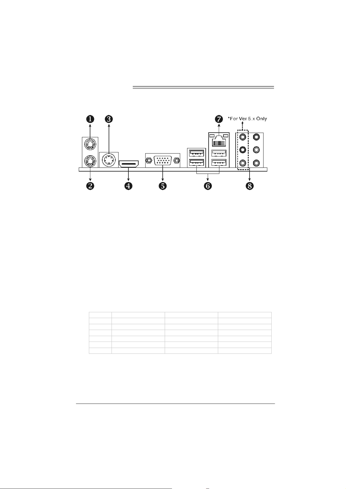
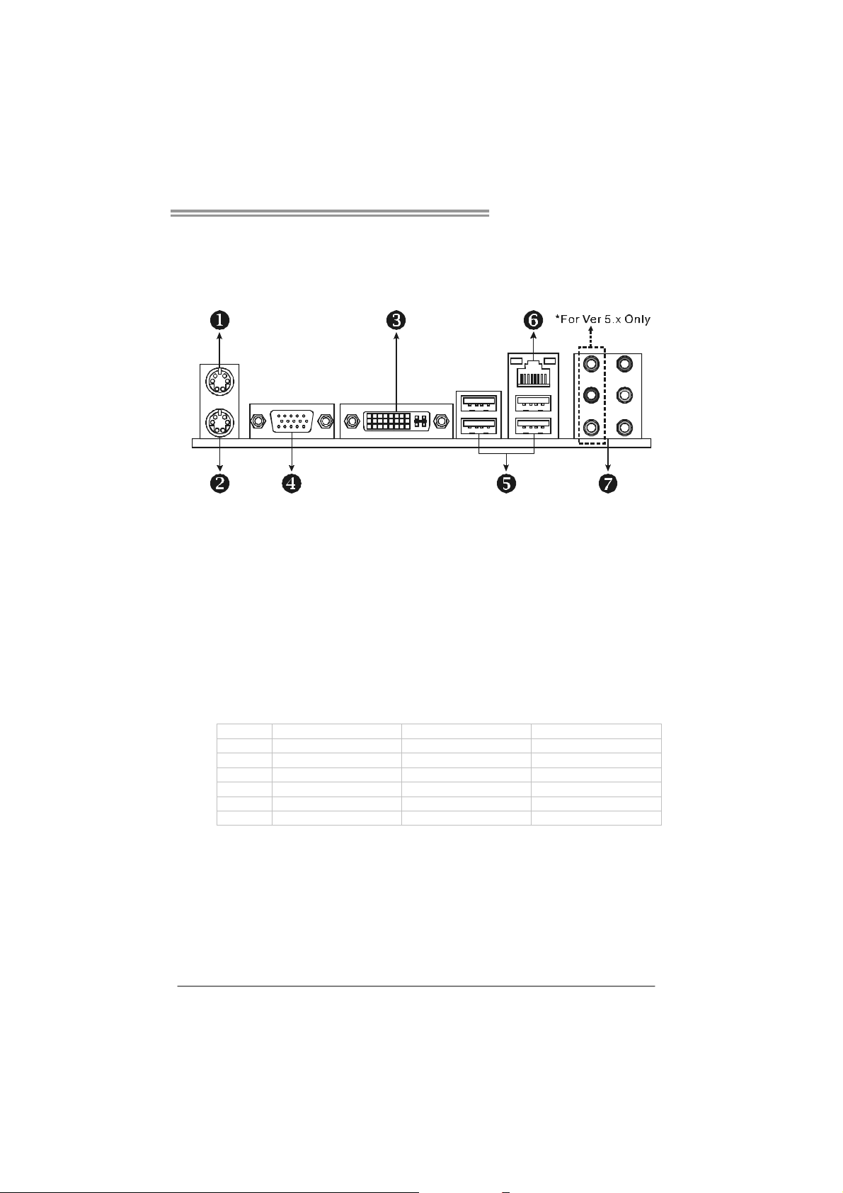
1.4 REAR PANEL CONNECTORS (FOR TF7050-M2)
X PS/2 Mouse Port Y PS/2 Keyboard Port
S-Video TV-Out Port
Z
Trans mit analog video signals to TV or any other display panels equipped with S-Video
input.
HDMI Port
[
The High-Definition Multimedia Interface (HDMI) is an all-digital audio/video interface
capable of transmitting uncompressed streams to a n AV receiver or a ny compatible digital
audio and/or video monitor, such as a digital television.
D-Sub VGA Port
\
Trans mit analog video signals to computer monitor or any othe r display panels equipped
with D -Sub VGA i nput.
USB 2.0 Port x 4
]
RJ-45 LAN Port
^
Audio Jack x 6 (for Ver 5.x) / Audio Jack x 3 (for Ver 6.x)
_
Port 2-Channel 4-Channel 6-Channel/8-Channel
Blue Li ne-In Li ne- In L ine- In
Green Line-Out Front Speaker Out Front Speaker Out
Pink Mic In Mic In Mic In
Orange Cente r/S ubwoofer
Black Rear Speaker Out Rear Speaker Out Rear Speaker Out
Grey Side Speaker Out
NOTE: The GeForce 7050PV/NF630a chipset uses the same channe l to control S-Video and
6
D-Sub for transmitting analog video signals, so these ports cannot work simultaneously.
Page 7
TF7050-M2/TF7025-M2
1.5 REAR PANEL CONNECTORS (FOR TF7025-M2)
X PS/2 Mouse Port Y PS/2 Keyboard Port
DVI-D VGA Port
Z
The Digital Visual Interface (DVI) is a video interface transmitting digital video signals to
digital display de vices such as flat panel LCDs or digital projectors. The DVI-D connector
allows digital signals transmission only.
D-Sub VGA Port
[
Trans mit analog video signals to computer monitor or any othe r display panels equipped
with D -Sub VGA i nput.
USB 2.0 Port x 4
\
RJ-45 LAN Port
]
Audio Jack x 6 (for Ver 5.x) / Audio Jack x 3 (for Ver 6.x)
^
Port 2-Channel 4-Channel 6-Channel/8-Channel
Blue Li ne-In Li ne- In L ine- In
Green Line-Out Front Speaker Out Front Speaker Out
Pink Mic In Mic In Mic In
Orange Cente r/S ubwoofer
Black Rear Speaker Out Rear Speaker Out Rear Speaker Out
Grey Side Speaker Out
7
Page 8
Motherboard Manual
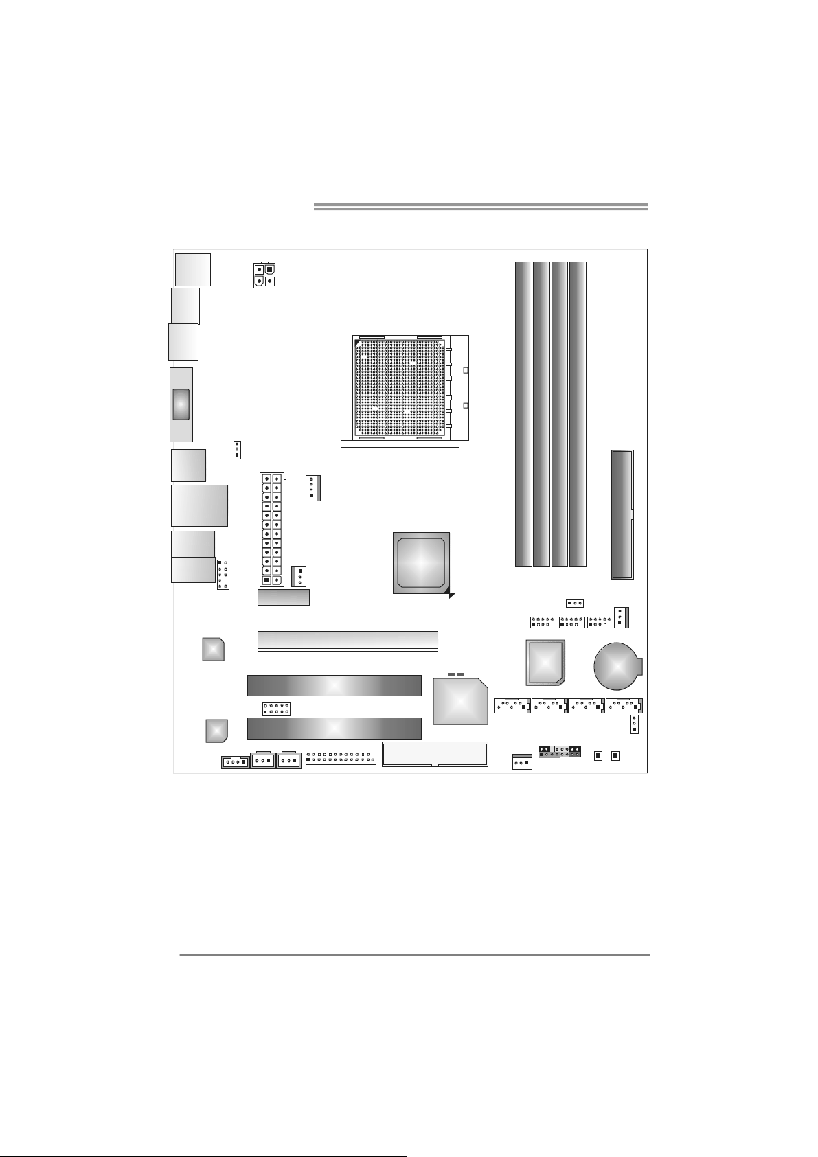
1.6 MOTHERBOARD LAYOUT (FOR TF7050-M2)
JKBMS1
JTVOUT1
JHDMI
JATXPWR2
Socket A M2
VGA
JUSB1
JUSBLAN1
JAUDIO2
(for V er 5.x)
JAUDIO1
(for V er 6.x)
JCDIN1
JUSBV1
JAUDIOF1
LAN
Codec
Note: represents the 1■
JATXPWR1
PEX1_1
JSPDIF_OUT 1JSPDIF_IN1
JCFAN1
JNFAN1
JCOM1
PEX16_1
PCI1
PCI2
JPRNT1
st
pin.
GeForce
7050PV/
FDD1
aNF630
LED_D1
LED_D2
Super I/O
DIMMA1
DIMMB1
JUSB2 JUSB3 JUSB4
BIOS
SATA 2SATA1
JPANEL1
JSFAN1
DIMMB2
DIMMA2
JUSBV2
BAT1
SATA 3 SATA 4
JCMOS1
PWRSW 1 RSTSW1
IDE1
JSFAN2
8
Page 9
TF7050-M2/TF7025-M2
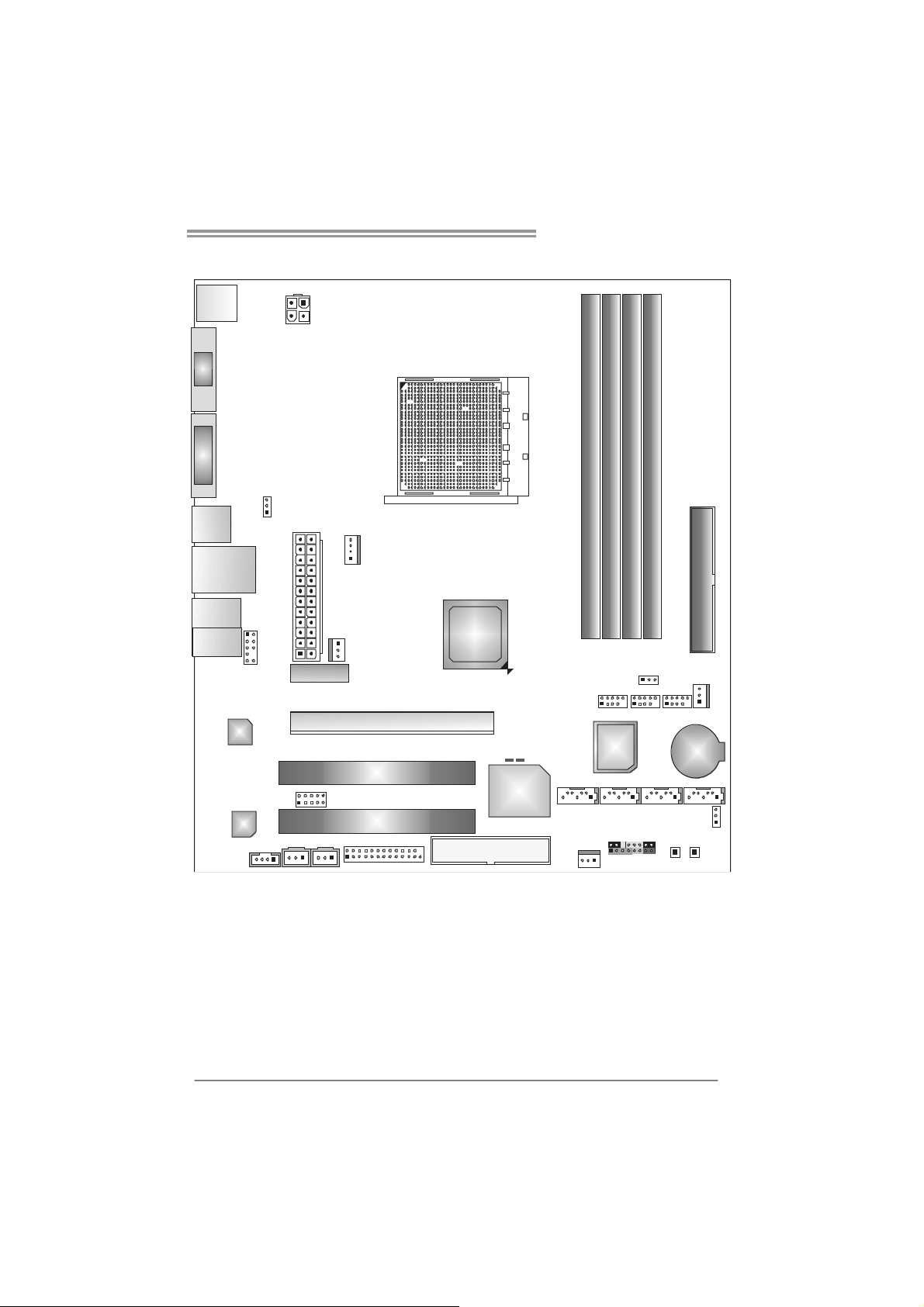
1.7 MOTHERBOARD LAYOUT (FOR TF7025-M2)
JKBMS1
JATXPWR2
VGA
Socket A M2
DVI-D
JUSB1
JUSBLAN1
JAUDI O2
(for Ver 5.x)
JA UDIO 1
(for Ver 6.x)
JCDIN1
JUSBV1
JAUDIOF1
LAN
Codec
Note: represents the 1■
JATXPWR1
PEX1_1
JSPDIF_OUT1JSPDIF_IN1
JCFAN1
JNFAN1
JCOM1
PEX16_1
PCI1
PCI2
JPRNT1
st
pin.
GeForce
7025 /
FDD1
aNF630
LED_D1
LED_D2
Super I/O
DIMMA1
DIMMB1
JUSB2 JUSB3 JUSB4
BIO S
SATA 2SA TA1
JPANEL1
JSFAN1
DIMMB2
DIMMA2
JUSBV2
BAT1
SATA3 SATA4
JCMOS1
PWR SW 1 RS TS W1
IDE1
JSFAN2
9
Page 10
Motherboard Manual
CHAPTER 2: HARDWARE INSTALLATION
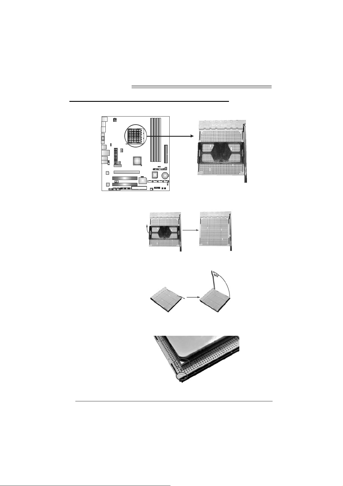
2.1 I
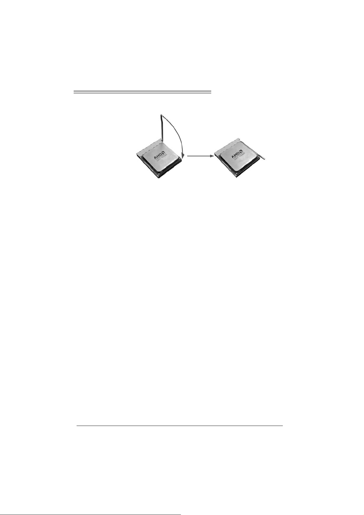
NSTALLING CENTRAL PROCESSING UNIT (CPU)
Step 1: Remove the socket protection cap.
Step 2: Pull the lever toward direction A from the socket and then raise the
lever up to a 90-degree angle.
Step 3: Look for the white triangle on socket, and the gold triangle on
CPU should point towards this white triangle. The CPU will fit only
in the correct orientation.
10
Page 11
TF7050-M2/TF7025-M2
Step 4: Hold the CPU down firmly, and then close the lever toward direct
B to complete the installation.
Step 5: Put the CPU Fan on the CPU and buckle it. Connect the CPU
FAN power cable to the JCFAN1. This completes the installation.
11
Page 12
Motherboard Manual
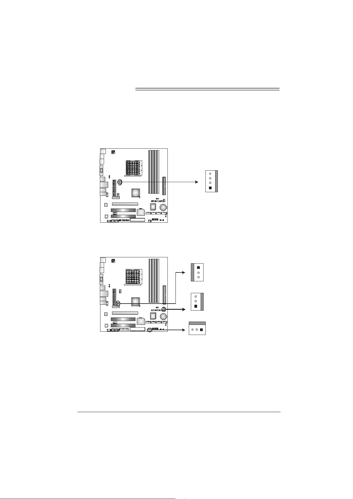
2.2 FAN HEADERS
These fan headers support cooling-fans built in the computer. The fan
cable and connector may be different according to the fan manufacturer.
Connect the fan cable to the connector while matching the black wire to
pin#1.
JCFAN1: CPU Fan Header
4
1
JNFAN1: North Bridge Fan Header
JSFAN1/JSFAN2: System Fan Header
JNFAN1
1
3
JSFAN2
3
1
Pin
1 Ground
2 +12V
3
4 Smart Fan
Pin
Assignment
FAN RPM r ate
sense
Control (By Fan)
Assignment
1 Ground
2 +12V
3 FAN RPM
rate sense
12
JSFAN1
13
Note:
The JCFAN1 supports 4-pin head connector. The JSFAN1/JSFAN2 and JNFAN1
support 3-pin head connectors. When connecting with wires onto connectors, please
note that the red wire is the positive and should be connected to pin#2, and the black
wire is Ground and s hould be connected to GND.
Page 13
TF7050-M2/TF7025-M2
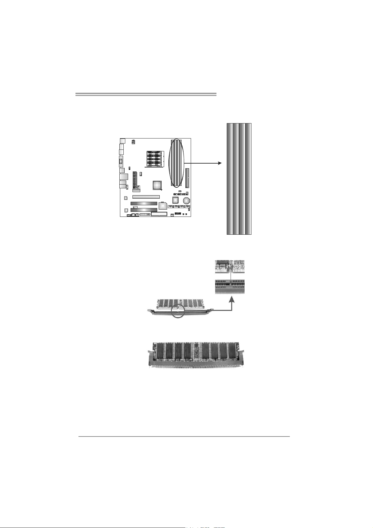
2.3 INSTALLING SYSTEM MEMORY
A. Memory Modules
DIMMA1
DIMMB1
DIMMA2
DIMMB2
1. Unlock a DIMM slot by pressing the retaining clips outward. Align a
DIMM on the slot such that the notch on the DIMM matches the
break on the Slot.
2. Insert the DIMM vertically and firmly into the slot until the retaining
chip snap back in place and the DIMM is properly seated.
13
Page 14
Motherboard Manual
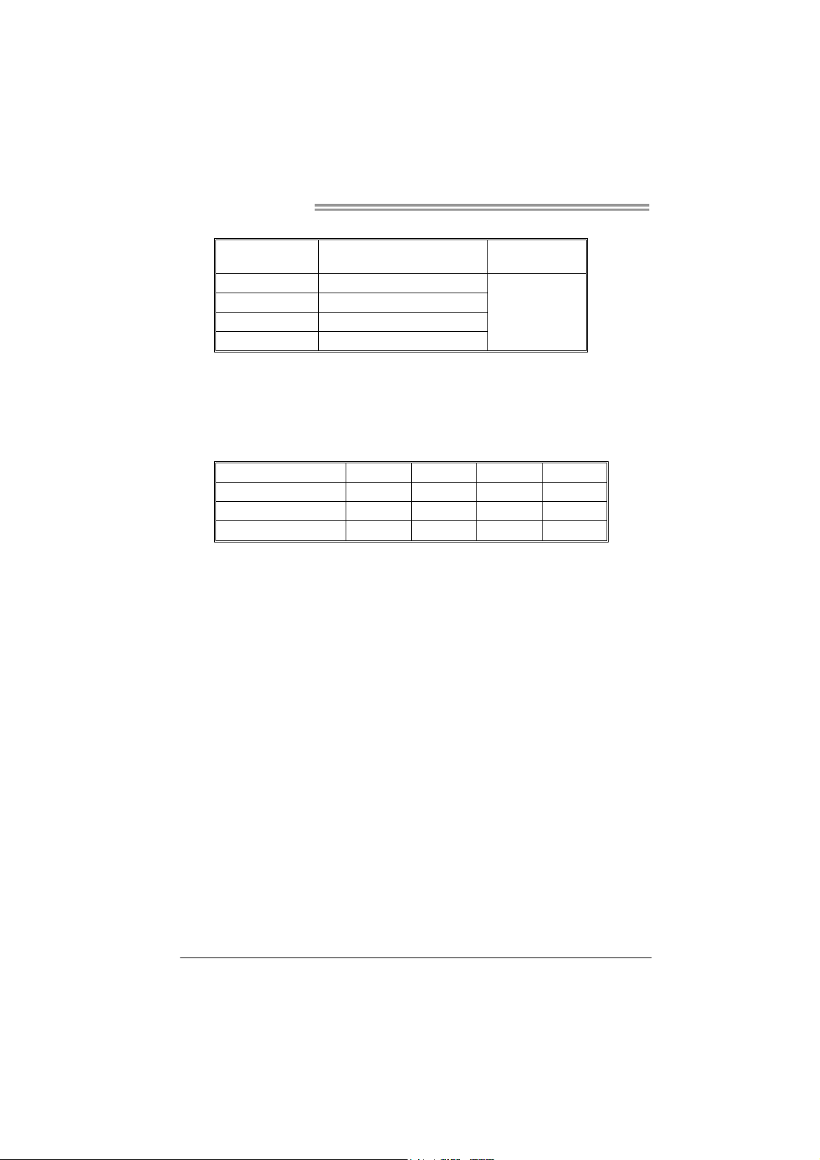
B. Memory Capacity
DIMM Socket
Location
DIMMA1 256MB/512MB/1GB/2GB
DIMMB1 256MB/512MB/1GB/2GB
DIMMA2 256MB/512MB/1GB/2GB
DIMMB2 256MB/512MB/1GB/2GB
DDR2 Module
C. Dual Channel Memory installation
To trigger the Dual Channel function of the motherboard, the memory module
must meet the following requirements:
Install memory module of the same density in pairs, shown in the following table.
Dual Channel Status
Enabled O O X X
Enabled X X O O
Enabled O O O O
(O means memory installed, X means memory not installed.)
The DRAM bus width of the memory module must be the same (x8 or
x16)
DIMMA1
Total Mem o ry
Size
Max is 8GB.
DIMMB1 DIMMA2 DIMMB2
14
Page 15
TF7050-M2/TF7025-M2
2.4 CONNECTORS AND SLOTS
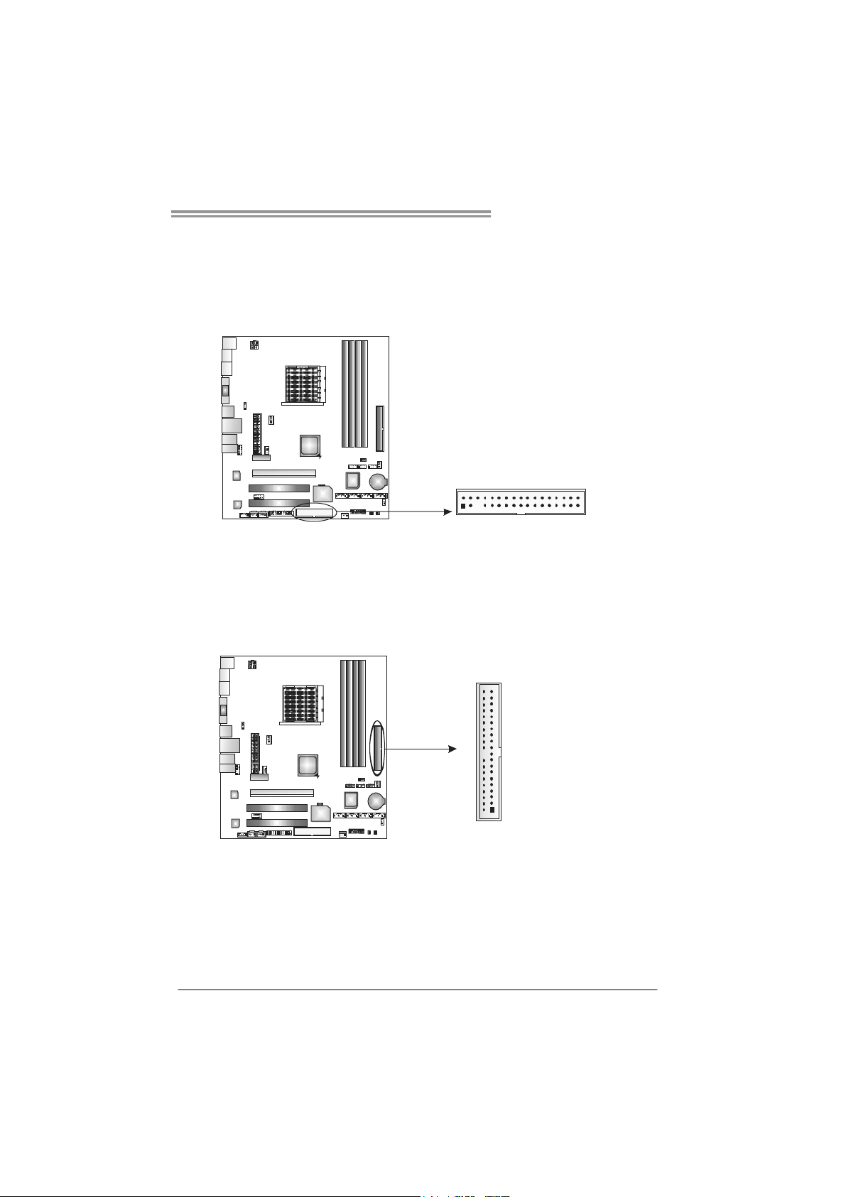
FDD1: Floppy Disk Connector
The motherboard provides a standard floppy disk connector that supports 360K,
720K, 1.2M, 1.44M and 2.88M floppy disk types. This connector supports the
provided floppy drive ribbon cables.
234
IDE1: Hard Disk Connector
The motherboard has a 32-bit Enhanced PCI IDE Controller that provides PIO
Mode 0~4, Bus Master, and Ultra DMA 33/66/100/133 functionality.
The IDE connector can connect a master and a slave drive, so you can connect
up to two hard disk drives.
133
3940
21
15
Page 16
Motherboard Manual
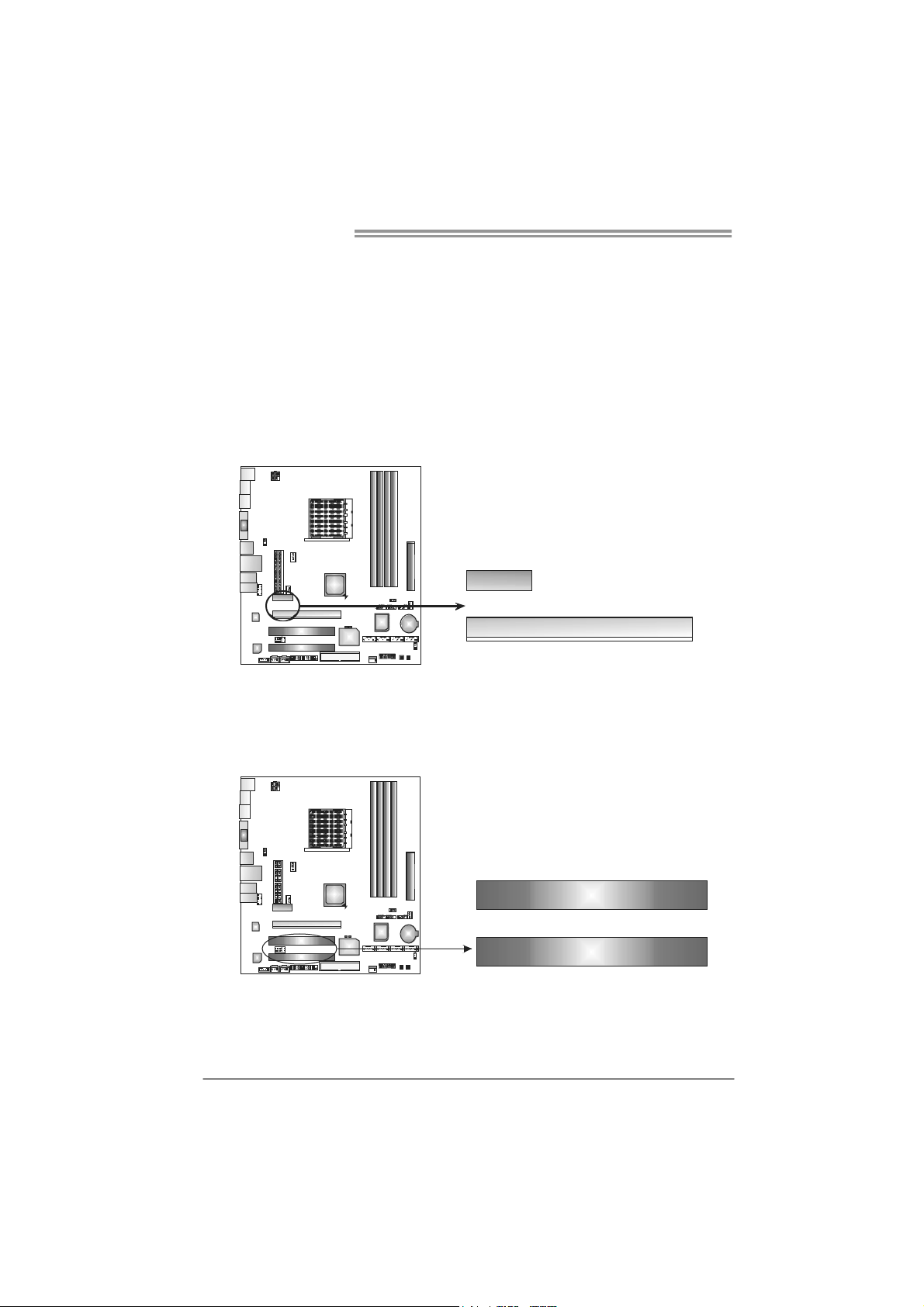
PEX16_1: PCI-Express x16 Slot
- PCI-Express 1.0a compliant.
- Maximum theoretical realized bandwidth of 4GB/s simultaneously per
direction, for an aggregate of 8GB/s totally.
PEX1_1: PCI-Express x1 Slot
- PCI-Express 1.0a compliant.
- Data transfer bandwidth up to 250MB/s per direction; 500MB/s in total.
- PCI-Express supports a raw bit-rate of 2.5GB/s on the data pins.
- 2X bandwidth over the traditional PCI architecture.
PEX1_1
PEX16_ 1
PCI1~PCI2: Peripheral Component Interconnect Slots
This motherboard is equipped with 2 standard PCI slots. PCI stands for
Peripheral Component Interconnect, and it is a bus standard for expansion
cards. This PCI slot is designated as 32 bits.
16
PCI1
PCI2
Page 17
TF7050-M2/TF7025-M2
CHAPTER 3: HEADERS & JUMPERS SETUP
3.1 H
OW TO SETUP JUMPERS
The illustration shows how to set up jumpers. When the jumper cap is
placed on pins, the jumper is “close”, if not, that means the jumper is
“open”.
Pin opened Pin closed Pin1-2 closed
3.2 DETAIL SETTINGS
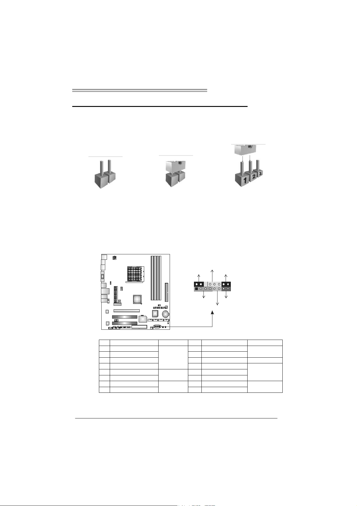
JPANEL1: Front Panel Header
This 16-pin connector includes Power-on, Reset, HDD LED, Power LED, Sleep
button and speaker connection. It allows user to connect the PC case’s front
panel switch functions.
PW R_LED
SLP
9
1
SPK
++
HLED
+
On/Off
-
-
RST
16
8
Pin Assignment Function Pin Assignment Function
1 +5V 9 Sleep control
2 N/A 10 Ground
3 N/ A 11 N/ A N/A
4 Speaker
5 HDD LED (+) 13 Power LED (+)
6 HDD LED (-)
7 Ground 15 Power button
8 Reset control
Speaker
Connector
Hard drive
LED
Reset button
12 Power LED (+)
14 Power LED (-)
16 Ground
Sleep button
Power LED
Power-on button
17
Page 18
Motherboard Manual
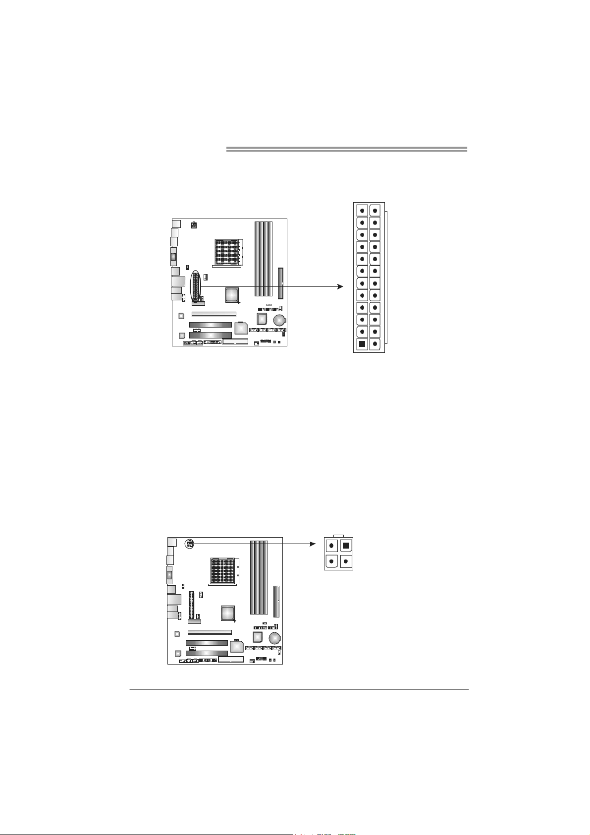
JATXPWR1: AT X Power Source Connector
This connector allows user to connect 24-pin power connector on the ATX
power supply.
12
1
Pin Assignment Pin Assignment
13 +3.3V 1 +3.3V
14 -12V 2 +3.3V
15 Ground 3 Ground
16 PS_ON 4 +5V
17 Ground 5 Ground
18 Ground 6 +5V
19 Ground 7 Ground
20 NC 8 PW_OK
21 +5V 9 Standby Voltage+5V
22 +5V 10 +12V
23 +5V 11 +12V
24 Ground 12 +3.3V
24
13
JATXPWR2: AT X Power Source Connector
By connecting this connector, it will provide +12V to CPU power circuit.
18
324
1
Pin
1 +12V
2 +12V
3 Ground
4 Ground
Assignment
Page 19
TF7050-M2/TF7025-M2
SATA1~SATA4: Serial ATA Connectors
The motherboard has a PCI to SATA Controller with 4 channels SATA interface.
SATA 1
SATA3
SATA2 SATA4
147
JUSB2/JUSB3/JUSB4: Headers for USB 2.0 Ports at Front Panel
This header allows user to connect additional USB cable on the PC front panel,
and also can be connected with internal USB devices, like USB card reader.
Pin Assignment
JUSB2
JU SB3
JUSB4
2
1
10
9
Pin
Assignment
1 Ground
2 TX+
3 TX4 Ground
5 RX6 RX+
7 Ground
1 +5V (fused)
2 +5V (fused)
3 USB-
4 USB-
5 USB+
6 USB+
7 Ground
8 Ground
9 Key
10 NC
19
Page 20
Motherboard Manual
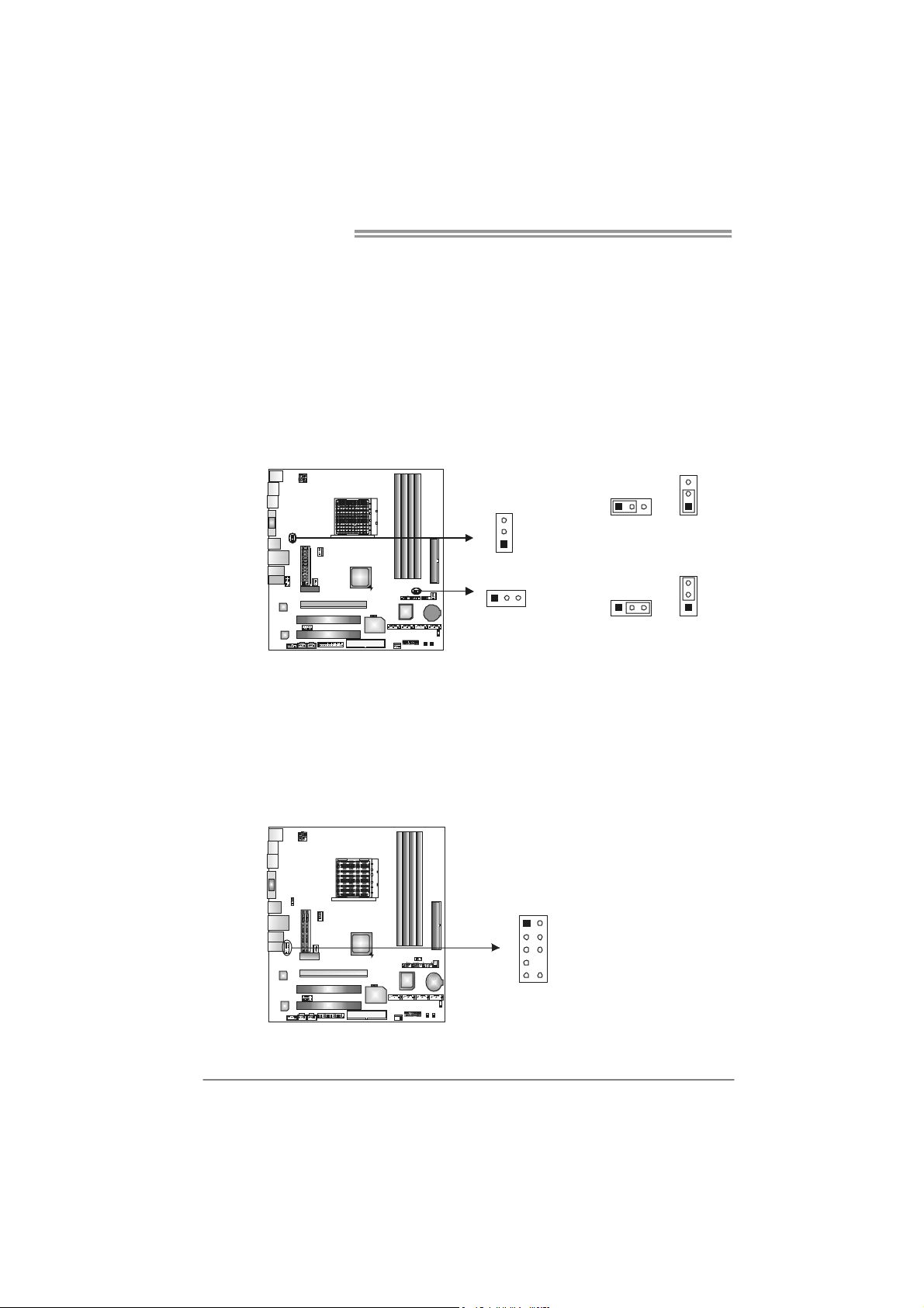
JUSBV1/JUSBV2: Power Source Headers for USB Ports
Pin 1-2 Close:
JUSBV1: +5V for USB ports at JUSB1/JUSBLAN1.
JUSBV2: +5V for USB ports at front panel (JUSB2/JUSB3/JUSB4).
Pin 2-3 Close:
JUSBV1: USB ports at JUSB1/JUSBLAN1 are powered by +5V standby
voltage.
JUSBV2: USB ports at front panel (JUSB2/JUSB3/JUSB4) are powered by
+5V standby voltage.
JUSBV1
3
1
Pin 1-2 close
3
3
1
113
JUSBV2
1
Pin 2-3 close
3
3
1
Note:
In order to support this function “Power-On system via USB device,” “JUSBV1/ JUSBV2”
jumper cap should be placed on Pin 2-3 individually.
JAUDIOF1: Front Panel Audio Header
This header allows user to connect the front audio output cable with the PC front
panel. It will disable the output on back panel audio connectors.
Pin Assignment
1 Mic Left in
2 Ground
3 Mic Right in
1
9
2
10
4 GPIO
5 Right line in
6 Jack Sense
7 Front Sense
8 Key
9 Left line in
10 Jack Sense
20
Page 21
TF7050-M2/TF7025-M2
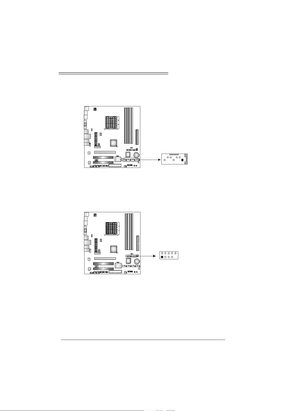
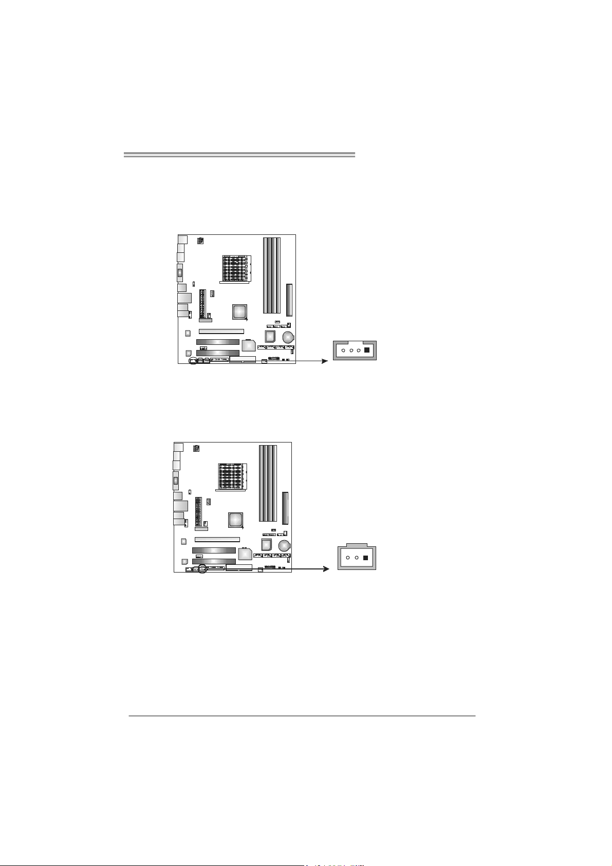
JCDIN1: CD-ROM Audio-in Connector
This connector allows user to connect the audio source from the variaty devices,
like CD-ROM, DVD-ROM, PCI sound card, PCI TV turner card etc..
Assignment
Pin
1 Left Channel
Input
2 Ground
3 Ground
4 Right Channel
14
Input
JSPDIF_OUT1: Digital Audio-out Connector
This connector allows user to connect the PCI bracket SPDIF output header.
Pin
Assignment
1 +5V
2 SPDIF_OUT
3 Ground
13
21
Page 22

Motherboard Manual
JSPDIF_IN1: Digital Audio-out Connector (Optional)
This connector allows user to connect the PCI bracket SPDIF input header.
JCMOS1: Clear CMOS Header
By placing the jumper on pin2-3, it allows user to restore the BIOS safe setting
and the CMOS data, please carefully follow the procedures to avoid damaging
the motherboard.
3
1
Pin
Assignment
1 +5V
2 SPDIF_IN
3 Ground
13
3
1
Pin 1-2 Close:
Normal Operation
(default).
3
1
Pin 2-3 Close:
Clear CMOS data.
22
※ Clear CMOS Procedures:
1. Remove AC power line.
2. Set the jumper to “Pin 2-3 close” .
3. Wait for five seconds.
4. Set the jumper to “Pin 1-2 close” .
5. Power on the AC.
6. Reset your desired password or clear the CMOS data.
Page 23

TF7050-M2/TF7025-M2
On-Board Buttons
There are 2 on-board buttons.
PWRSW1 RSTSW1
PWRSW1:
This is an on-board Power Switch button.
RSTSW1:
This is an on-board Reset button.
On-Board LED Indicators
There are 2 LED indicators on the motherboard to show system status.
LED_D1
LED_D2
LED_D1 and LED_D2:
These 2 LED indicate system power on diagnostics.
Please refer to the table below for different messages:
LED_D1 LED_D2 Message
ON ON Normal
ON OFF Memory Error
OFF ON VGA Erro r
OFF OFF Abnormal: CPU / Chipset error.
23
Page 24

Motherboard Manual
JPRNT1: Printer Port Connecto r
This header allows you to connector printer on the PC.
2
1
25
Pin Assignment Pin Assignment
1 -Strobe 14 Ground
2 -ALF 15 Data 6
3 Data 0 16 Ground
4 -Error 17 Data 7
5 Data 1 18 Ground
6 -Init 19 -ACK
7 Data 2 20 Ground
8 -Scltin 21 Busy
9 Data 3 22 Ground
10 Ground 23 PE
11 Data 4 24 Ground
12 Ground 25 SCLT
13 Data 5 26 Key
JCOM1: Serial Port Connector
The motherboard has a Serial Port Connector for connecting RS-232 Port.
Pin
Assignment
210
19
1 Carrier detect
2 Received data
3 Transmitted data
4 Data terminal ready
5 Signal ground
6 Data set ready
7 Request to send
8 Clear to send
9 Ring indicator
10 Key
24
Page 25

CHAPTER 4: RAID FUNCTIONS
TF7050-M2/TF7025-M2
4.1 O
z Supports Windows XP Home/Professional Edition, and Windows 2000 Professional.
PERATION SYSTEM
4.2 RAID ARRAYS
RAID supports the following types of RAID arrays:
RAID 0: RAID 0 defines a disk striping scheme that improves disk read and write times for
many applications.
RAID 1: RAID 1 defines techniques for mirroring data.
RAID 0+1: RAID 0+1 combines the techniques used in R AID 0 and RAID 1.
RAID 5: RAID 5 provides fault to lerance and better utilization of disk capacity.
4.3 HOW RAID WORKS
RAID 0:
The controller “stripes” data across multiple drives in a RAID 0 array system. It breaks
up a lar ge f ile in to sm aller blocks and p er forms disk reads a nd w rites across mult ip le
drives in parallel. The size of each block is determined by the stripe size parameter,
which you set during the creation of the RAID set based on the system environment. This
technique reduces overall disk access time and offers high bandwidth.
Features and Benefits
Drives: Minimum 1, and maximum is up to 6 or 8. Depending on the
platform.
Uses: Intended for non-critical data requiring high data throughput, or any
environment that does not require fault tolerance.
Benefits: provides increased data throughput, especially for large files. No
capacity loss penalty for parity.
Drawbacks: Does not deliver any fault tolerance. If any drive in the array
fails, all data is lost.
Fault Tolerance: No.
Block 1
Block 3
Block 5
Block 2
Block 4
Block 6
25
Page 26

Motherboard Manual
RAID 1:
Every read and write is actually carried out in parallel across 2 disk drives in a RAID 1
array system. The mirrored (backup) copy of the data can reside on the same disk or on a
second redundant drive in the array. RAID 1 provides a hot-standby copy of data if the
active volume or drive is corrupted or becomes unavailable because of a hardware failure.
RAID techniques can be applied for high-availability solutions, or as a form of automatic
backup that eliminates tedious manual backups to more expensive and less reliab le
media.
Features and Benefits
Drives: Minimum 2, and maximum is 2.
Uses: RAID 1 is ideal for small databases or any other application that
requires fault tolerance and minimal capacity.
Benefits: Provides 100% data redundancy. Should one drive fail, the
controller switches to the other drive.
Drawbacks: Requires 2 drives for the storage space of one drive.
Performance is impaired during drive rebuilds.
Fault Tolerance: Yes.
26
Block 1
Block 2
Block 3
Block 1
Block 2
Block 3
Page 27

TF7050-M2/TF7025-M2
RAID 0+1:
RAID 0 drives can be mirrored using RAID 1 techniques. Resulting in a RAID 0+1
solution for improved performance plus resiliency.
Features and Benefits
Drives: Minimum 4, and maximum is 6 or 8, depending on the platform.
Benefits: Optimizes for both fault tolerance and performance, allowing for
automatic redundancy. May be simultaneously used with other RAID levels
in an array, and allows for spare disks.
Drawbacks: Requires twice the available disk space for data redundancy,
the same as RAID level 1.
Fault Tolerance: Yes.
GeForce
7050PV
or
GeForce
7025
Block 1
Block 3
Block 5
Block 2
Block 4
Block 6
Block 1
Block 3
Block 5
Block 2
Block 4
Block 6
27
Page 28

Motherboard Manual
RAID 5:
RAID 5 stripes both data and parity information across three or more drives. It writes
data and parity blocks across all the drives in the array. Fault tolerance is maintained by
ensuring that the parity information for any given block of data is placed on a different
drive from those used to store the data itself.
Features and Benefits
Drives: Min i mu m 3.
Uses: RAID 5 is recommended for transaction processing and general
purpose service.
Benefits: An ideal combination of good performance, good fault tolerance,
and high capacity and storage efficiency.
Drawbacks: Individual block data transfer rate same as a single disk. Write
performance can be CPU intensive.
Fault Tolerance: Yes.
Disk 1
DATA 1
DATA 3
PARITY
DATA 7
DATA 9
PARITY
Disk 2
GeForce
7050PV
or
GeForce
7025
DATA 2
PARITY
DATA 5
DATA 8
PARITY
DATA 11
Disk 3
PARITY
DATA 4
DATA 6
PARITY
DATA 10
DATA 12
※ For more detailed setup information, please refer to the Driver CD, or go to
http://www.nvidia.com/page/pg_20011106217193.html to download NVIDIA nForce Tutorial Flash.
28
Page 29

TF7050-M2/TF7025-M2
CHAPTER 5: OVERCLOCK QUICK GUIDE
5.1 T-P
OWER INTRODUCTION
Biostar T-Power is a whole new utility that is designed for overclock users.
Based on many precise tests, Biostar Engineering Team (BET) has
developed this ultimate overclock engine to raise system performance.
No matter whether under BIOS or Windows interface, T-Power is able to
present the best system state according to users’ overclock setting.
T-Power BIOS Features:
Overclocking Navigator Engine (O.N.E.)
CMOS Reloading Program (C.R.P.)
Memory Integration Test (M.I.T., under Overclock Navigator Engine)
Integrated Flash Program (I.F.P.)
Smart Fan Function (under PC Health Status)
Self Recovery System (S.R.S)
T-Power Windows Feature:
Hardware Monitor
Overclock Engine
Smart Fan Function
Live Update
!! WARNING !!
For better system performance, the BIOS firmware is being
continuously updated. The BIOS information described below in
this manual is for your reference only and the actual BIOS
information and settings on board may be different from this
manual. For further information of setting up the BIOS, please
refer to the BIOS Manual in the Setup CD.
29
Page 30

Motherboard Manual
5.2 T-POWER BIOS FEATURE
A. Overclocking Navigator Engine (O.N.E.):
ONE provides two powerful overclocking engines: MOS and AOS for both
Elite and Casual overclockers.
Manual Overclock System (M.O.S.)
MOS is designed for experienced overclock users.
It allows users to customize personal overclock settings.
30
↓
Page 31

TF7050-M2/TF7025-M2
CPU Frequency
CPU Frequency is directly in proportion to system performance. To
maintain the system stability, CPU voltage needs to be increased also
when raising CPU frequency.
K8<->NB HT Speed
This function allows you to choose K8<->NB HT Speed.
K8<->NB HT Width
This function allows you to choose K8<->NB HT Width.
Onboard GPU Overclock
This function allows you to set the onboard GPU frequency.
DRAM Configuration
Enter this item for more advanced DRAM settings.
CPU Spread Spectrum
This item allows you to select the CPU Spread Spectrum function.
PCIE Spread Spectrum
This item allows you to select the PCIE Spread Spectrum function.
SATA Spread Spectrum
This item allows you to select the SATA Spread Spectrum function.
iGPU Spread Spectrum
This item allows you to select the iGPU Spread Spectrum function.
PCIE Clock
It helps to increase VGA card performance.
NPT Fid Contro l
This function allows you to adjust the frequency ratio of CPU.
Ti mi ng Mode
This function allows you to choose to manually or automatically regulate
the DDR2 timing.
Memory Clock Value or Limit
This function allows you to choose the DRAM clock.
CAS Latency
The CAS Latency (tCL) is the time (in number of clock cycles) that elapses
after the memory controller sends a request to read a memory location
and before the data is sent to the module's output pins.
DRAM Command Mode
This function allows you to choose the command mode of DRAM.
CPU Voltage
This function will increase CPU stability when overclocking. However, the
CPU temperature will increase when CPU voltage is increased.
31
Page 32

Motherboard Manual
DDR Voltage
This function will increase memory stability when overclocking.
NB Voltage
This function will increase chipset stability when overclocking.
Automatic Overclock System (A.O.S.)
For beginners in overclock field, BET had developed an easy, fast, and
powerful feature to increase the system performance, named A.O.S.
Based on many tests and experiments, A.O.S. provides 3 ideal overclock
configurations that are able to raise the system performance in a single
step.
V6 Tech Engine:
This setting will raise about 10%~15% of whole system performance.
32
Page 33

TF7050-M2/TF7025-M2
V8 Tech Engine:
This setting will raise about 15%~25% of whole system performance.
V12 Tech Engine:
This setting will raise about 25%~30% of whole system performance.
Notices:
1. Not all types of AMD CPU perform above overclock setting ideally; the difference will be based
on the selected CPU model.
2. From BET experiments, the Atholon64 FX CPU is not suitable for this A.O.S. feature.
33
Page 34

Motherboard Manual
B. CMOS Reloading Program (C.R.P.):
It allows users to save different CMOS settings into BIOS-ROM.
Users are able to reload any saved CMOS setting for customizing system
configurations.
Moreover, users are able to save an ideal overclock setting during overclock
operation.
There are 50 sets of record addresses in total, and users are able to name the
CMOS data according to personal preference.
34
Page 35

TF7050-M2/TF7025-M2
C. Memory Integration Test (M.I.T.):
This function is under “Overclocking Navigator Engine” item.
MIT allows users to test memory compatibilities, and no extra devices or
software are needed.
Step 1:
The default setting under this item is “Disabled”; the condition parameter should
be changed to “Enable” to proceed this test.
↓
Step 2:
Save and Exit from CMOS setup and reboot the system to activate this test.
Run this test for 5 minutes (minimum) to ensure the memory stability.
Step 3:
When the process is done, change the setting back from “Enable” to “Disable”
to complete the test.
35
Page 36

Motherboard Manual
D. Self Recovery System (S.R.S.):
This function can’t be seen under T-Power BIOS setup; and is always on
whenever the system starts up.
However, it can prevent system hang-up due to inappropriate overclock
actions.
When the system hangs up, S.R.S. will automatically log in the default BIOS
setting, and all overclock settings will be re-configured.
E. Integrated Flash Program (I.F.P.):
IFP is a safe and quick way to upgrade BIOS.
Step 1:
Go to Biostar website (http://www.biostar.com.tw
file. Then, save the file into a floppy disk.
Step 2:
Insert the floppy disk and reboot the system to get into CMOS screen.
Step 3:
Select the item “Integrated Flash Program” to get the following frame and
choose the BIOS file downloaded in step 1.
) to download the latest BIOS
36
Step 4:
Press “Enter” key to start BIOS file loading, and BIOS updating will process
automatically.
Step 5:
When the BIOS update is completed, press YES to the message “Flash done,
Reset system”, and the system will reboot automatically to finish the process.
Advise:
You can update the system BIOS by simply pressing “Enter” key for three times.
Page 37

TF7050-M2/TF7025-M2
F. Smart Fan Function:
Smart Fan Function is under “Smart Fan Option” in “PC Health Status”.
This is a brilliant feature to control CPU/System Temperature vs. Fan speed.
When enabling Smart Fan function, Fan speed is controlled automatically by
CPU/System temperature.
This function will protect CPU/System from overheat problem and maintain the
system temperature at a safe level.
↓
Smart Fan Calibration
Choose this item and then the BIOS will automatically test and detect the
CPU/System fan functions and show CPU/System fan speed.
PWM Duty Off <℃>:
If the CPU/System temperature is lower than the set value, the
CPU/System fan will turn off. The range is from 0℃~127℃, with an
interval of 1℃.
37
Page 38

Motherboard Manual
PWM Duty Start <℃>
The CPU/System fan starts to work when CPU/System temperature
arrives to this set value. The range is from 0℃~127℃, with an interval of
1℃.
Start PWM Value
When CPU/System temperature arrives to the set value, the CPU/System
fan will work under Smart Fan Function mode. The range is from 0~127,
with an interval of 1.
Smart Fan Slope
Increasing the value of slope PWM will raise the speed of CPU/System fan.
The range is from 1~127, with an interval of 1.
38
Page 39

TF7050-M2/TF7025-M2
5.3 T-POWER WINDOWS FEATURE
A.Hardware Monitor:
T-Power Hardware monitor allows users to monitor system voltage,
temperature and fan speed accordingly.
Additionally, a rescue action will be taken by the program automatically
while the system faces an abnormal condition. The program will trigger an
alarm or shut down the system when unpredictable errors occur.
All the monitoring items are illustrated by a waveform diagram.
Hardwa re Monitor Toolbar
i. Start-up Setting
Click on this item to run Hardware Monitor Program when the Windows
starts-up.
ii. Dialogue-Box Setting
Click on this item to pop-up warning dialogue-box when PC system is
abnormal.
iii. Exit
Click on this item to exit Hardware Monitor Program.
iv. Hide
Click on this item to hide this program in system tray. When hiding the
program, there will be a check icon in the system tray.
39
Page 40

Motherboard Manual
CPU Temperature
This column configures the CPU temperature. There is a waveform to
represent the status of CPU temperature.
By adjusting , users can easily configure the upper limit of CPU
temperature for system operating.
In this diagram, the white line represents the upper limit which user-set for CPU
temperature and the green line shows present CPU temperature.
If the CPU temperature is higher than the upper limit, the status line color will
change from green to red, and a warning sound will alert you. Also, the system
tray icon
would change to .
FAN Speed
40
By adjusting , users can easily configure the lower limit of the fan speed.
In this diagram, the green line shows present CPU Fan speed, and the yellow
line shows System Fan speed (if any).
If any one of the fans speeds is lower than the set value, the status line will
change into a red warning line, and the program will trigger an alarm system
automatically. Also, the system tray icon
would change to .
Page 41

TF7050-M2/TF7025-M2
CPU/Battery Voltage
i. VCore
This item displays the CPU voltage, represented by a light blue line.
Users can set the upper and lower limit by adjusting
CPU operating voltage.
If CPU voltage is higher or lower than the set value, the status line will
change into a red warning line, and a warning sound will alert you. Also,
the system tray icon
ii. VBAT
This item displays the CMOS battery voltage, represented by a light green
line.
Users can set the upper and lower limit by adjusting
status of battery voltage.
If battery voltage is higher or lower than the set value, the status line will
change to a red warning line, and a warning sound will alert you. Also, the
system tray icon
will change to .
will change to .
to monitor the
to monitor the
Reference data
This column represents the status of power supply voltage and cannot be
adjusted, it is only for present status reference.
41
Page 42

Motherboard Manual
B. Overclocking Configurations
This diagram is designed for T-series
Overclocking utility. Friendly interface and solid
overclock features are the major concept of this
utility.
Graphic 1 will appear when activating this utility.
Graphic 2
By adjusting the overclocking
features in 4 sub-screens, users can
tune the system performance to an
optimal level.
Graphic 1
A. Clicking on “Biostar” will lead you to the
Biostar Homepage.
B. This column shows the CPU speed
information.
C. Click on this button and the utility will
pop-up 4 sub-screens (Please refers to
Graphic 3).
D. Click on this button to minimize this
program to taskbar.
E. This column shows present CPU speed
and overclocking percentage.
F. Clicking on this button will make the
program start up as soon as the
Windows starts up.
G. Click on this button to exit this overclock
utility.
H. Click on this button to reset all the
overclock features to default setting.
42
Graphic 3
Page 43

CPU Overclocking Settings:
By adjust i ng can configure three items
for CPU overclocking.
A. CPU Frequency
Range: 200MHz~450MHz.
Inter val: 1 MHz.
B. CPU Ratio
Range: 4~25.
Inter val: 1 .
C. CPU Voltage
Range: 0.8V~2.0V.
Interval: 0.0125V.
Memory Overclocking Settings:
By adjust i ng can co nfig ur e tw o it ems f or
Memory overclocking.
A. Memory Clock Frequency
Choices: 100, 133, 200, 266, 333, 400, 533,
667, 800.
B. Memory Voltage
Range: 1.8V~2.8V.
Inter val: 0 .1V.
TF7050-M2/TF7025-M2
AGP/PCI-Express Overclocking Setting:
By adjust i ng can configure VGA card
overclocking. And this function helps to
increase VGA card performance.
Range: 100MHz~150MHz.
Inter val: 1 MHz.
43
Page 44

Motherboard Manual
PCI Overclocking Setting:
This diagram shows present PCI working
status and helps to monitor PCI peripherals
working status.
This item cannot be adjusted.
44
Page 45

TF7050-M2/TF7025-M2
C. Smart Fan Function
When Smart Fan Function is activated, screens will pop-up to illustrate
the fan speed information.
i. CPU Temperature:
Show current CPU temperature.
ii. CPU Fan speed:
Show current CPU Fan speed.
iii. System Fan speed:
Show current system Fan speed.
iv. Calibrate:
When changing CPU Fan or System Fan, click on this button to
re-calibrate the Fan speed.
Note:
1. Whe n Smart Fa n Function ac tivates for the first time, t his calibrate function wo uld
auto-run to get upper and lower limitation of CPU Fan and System Fan.
2. When calibrating process is done, the calibrating window will auto-close, and the
main screen will show new fan speed data.
45
Page 46

Motherboard Manual
v. Auto:
If the green indicator is lit up, the Smart Fan Function is “On”
(Default Setting).
Click on this button again to close Smart Fan Function, and a
screen as below would pop-up.
There will be pulling-meter besides the CPU Fan and System Fan,
the CPU Fan and the System Fan speed can be adjusted by
adjusting the Cursor Up or Down.
vi. Program Tool Bar:
z About:
Click on this button to get program-related information.
z Minimize:
Click on this button to minimize the program to system tray
46
z Exit:
Click on this button to exit this program.
Page 47

TF7050-M2/TF7025-M2
D. Live Update
When Live Update program is activated, a screen will pop up to illustrate
BIOS related information.
i. Link to Internet:
Click on this button will link to Biostar website and BIOS file will
be downloaded.
ii. Update BIOS:
Click on this button to run BIOS flashing process, and it’s easy
and safe.
iii. Backup BIOS:
Click on this button, and BIOS file will be saved into the
user-selected folder.
iv. Clear CMOS:
Click on this item will clear the CMOS Data. When carrying this
job, the prev ious CMOS data would be cleared and returned to
default setting.
47
Page 48

Motherboard Manual
CHAPTER 6: USEFUL HELP
6.1 D
RIVER INSTALLATION NOTE
After you installed your operating system, please insert the Fully Setup
Driver CD into your optical drive and install the driver for better system
performance.
You will see the following window after you insert the CD
The setup guide will auto detect your motherboard and operating system.
Note:
If this window didn’t show up after you insert the Drive r CD, please use file browser to
locate and execute the file SETUP.EXE under your optical drive.
A. Driver Installation
To install the driver, please click on the Driver icon. The setup guide will
list the compatible driver for your motherboard and operating system.
Click on each device driver to launch the installation program.
B. Software Installation
To install the software, please click on the Software icon. The setup guide
will list the software available for your system, click on each software title
to launch the installation program.
C. Manual
Aside from the paperback manual, we also provide manual in the Driver
CD. Click on the Manual icon to browse for available manual.
Note:
You will need Acrobat Reader to open the manual file. Please download the latest version
of Acrobat Reader so ftware from
http://www.adobe.com/products/acrobat/readstep2.html
48
Page 49

TF7050-M2/TF7025-M2
6.2 AWARD BIOS BEEP CODE
Beep Sound Meaning
One long beep followed by two short
beeps
High-low siren sound CPU overheated
One Short beep when system boot-up No error found during POST
Long beeps every other second No DRAM detected or install
Video card not found or video card
memory bad
System will shut down automatically
6.3 EXTRA INFORMATION
CPU Overheated
If the system shutdown automatically after power on system for
seconds, that means the CPU protection function has been activated.
When the CPU is over heated, the motherboard will shutdown
automatically to avoid a damage of the CPU, and the system may not
power on again.
In this case, please double check:
1. The CPU cooler surface is placed evenly with the CPU surface.
2. CPU fan is rotated normally.
3. CPU fan speed is fulfilling with the CPU speed.
After confirmed, please follow steps below to relief the CPU protection
function.
1. Remove the power cord from power supply for seconds.
2. Wait for seconds.
3. Plug in the power cord and boot up the system.
Or you can:
1. Clear the CMOS data.
(See “Close CMOS Header: JCMOS1” section)
2. Wait for seconds.
3. Power on the system again.
49
Page 50

Motherboard Manual
6.4 TROUBLESHOOTING
Probable Solution
1. No power to the system at all
Power light don’t illuminate, fan
inside power supply does not turn
on.
2. Indicator light on keyboard does
not turn on.
System inoperative. Keyboard lights
are on, power indicator lights are lit,
and hard drive is spinning.
System does not boot from hard disk
drive, can be booted from optical drive.
System only boots from optical drive.
Hard disk can be read and applications
can be used but booting from hard disk
is impossible.
Screen message says “Invalid
Configuration” or “CMOS Failure.”
Cannot boot system after installing
second hard drive.
1. Make sure power cable is
securely plugged in.
2. Replace cable.
3. Contact technical support.
Using even pressure on both ends of
the DIMM, press down firmly until the
module snaps into place.
1. Check cable running from disk to
disk controller board. Make sure
both ends are securely plugged
in; check the drive type in the
standard CMOS setup.
2. Backing up the hard drive is
extremely important. All hard
disks are capable of breaking
down at any time.
1. Back up data and applications
files.
2. Reformat the hard drive.
Re-install applications and data
using backup disks.
Review system’s equipment. Make sure
correct information is in setup.
1. Set master/slave jumpers
correctly.
2. Run SETUP program and select
correct drive types. Call the drive
manufacturers for compatibility
with other drives.
50
Page 51

TF7050-M2/TF7025-M2
This page is intentionally left blank.
51
Page 52

Motherboard Manual
APPENDENCIES: SPEC IN OTHER LANGUAGE
G
ERMAN
TF7050- M2 TF7025- M2
Sockel AM2
AMD Athlon 64 / Athlon 64 FX / Athlon 64 x2 /
CPU
FSB
Chipsatz GeForce 7050PV/NF630a GeForce 7025/NF630a
Super E/A
Arbeitsspeich
er
Grafik
IDE
SATA II
LAN
52
Sempron Prozessoren
Die AMD 64-Architektur unt ers tützt eine 32-Bitund 64-Bit-Datenverarbeitung
Unterstützt Hyper Transport und Cool’n’Quiet
Unterstützt HyperTransport mit einer Bandbreite
von bis zu 1 GHz
ITE 8716F
Biet et die häufig ver wend eten alten Super
E/A-Funktionen.
Low Pin Count-Schnittstelle
Umgebungskontrolle,
Hardware-Überwachung
Lüfterdrehza hl-Controller
"Smart Guardian"-Funktion von ITE
DDR2 DIMM-Steckplätze x 4
Max. 8GB Arbeitsspeicher
Jeder DIMM unterstützt 256/512MB/1GB/2GB
DDR2.
Dual-Kanal DDR2 Speichermodul
Unterstützt DDR2 400 / 533 / 667 / 800
registrierte DIMMs. ECC DIMMs werden nicht
unterstützt.
Integrierter GeForce 7050PV /NF630a-Chipsatz
Max. 256MB gemeinsam benutzter
Videospeicher
Int eg r iert er IDE- Controlle r
Ultra DMA 33 / 66 / 100 / 133 Bus
Master-Modus
Unterstützt PIO-Modus 0~4,
Integrierter Serial ATA-Controller
Datentransferrate b is zu 3Gb/s
Konform mit d er SATA-Spezifikation Version 2.0.
Realtek RTL 8111B / 8101E (optional)
10 / 100 / 1000 Mb/s Auto-Negotiation
(Gigabit-Bandbreite nur beim RTL 8111B )
Halb-/ Vollduplex-Funktion
Sockel AM2
AMD Athlon 64 / Athlon 64 FX / Athlon 64 x2/
Sempron Prozessoren
Die AMD 64-Architektur unt ers tützt eine 32-Bitund 64-Bit-Datenverarbeitung
Unterstützt Hyper Transport und Cool’n’Quiet
Unterstützt HyperTransport mit einer Bandbreite
von bis zu 1 GHz
ITE 8716F
Biet et die häufig ver wend eten alten Super
E/A-Funktionen.
Low Pin Count-Schnittstelle
Umgebungskontrolle,
Hardware-Überwachung
Lüfterdrehza hl-Controller
"Smart Guardian"-Funktion von ITE
DDR2 DIMM-Steckplätze x 4
Max. 8GB Arbeitsspeicher
Jeder DIMM unterstützt 256/512MB/1GB/2GB
DDR2.
Dual-Kanal DDR2 Speichermodul
Unterstützt DDR2 400 / 533 / 667 / 800
registrierte DIMMs. ECC DIMMs werden nicht
unterstützt.
Integrierter GeForce 7025/NF630a-Chipsatz
Max. 256MB gemeinsam benutzter
Videospeicher
Int eg r iert er IDE- Controlle r
Ultra DMA 33 / 66 / 100 / 133 Bus
Master-Modus
Unterstützt PIO-Modus 0~4,
Integrierter Serial ATA-Controller
Datentransferrate b is zu 3Gb/s
Konform mit d er SATA-Spezifikation Version 2.0.
Realtek RTL 8111B / 8101E (optional)
10 / 100 / 1000 Mb/s Auto-Negotiation
(Gigabit-Bandbreite nur beim RTL 8111B )
Halb-/ Vollduplex-Funktion
Page 53

TF7050-M2/TF7025-M2
TF7050- M2 TF7025- M2
Audio-Codec
Steckplätze
Onboard-Ans
chluss
Rückseiten-E
/A
Platinengröße
.
Sonderfunkti
onen
OS-Unterstüt
zung
ALC888 (Ver 5.x) / ALC861VD (Ver 6.x)
7.1-Kanal-Audioausgabe (Ver 5.x) /
5.1-Kanal-Audioausgabe (Ver 6.x)
Unterstützt High-Definition Audio
2-Kanal-Audioausgabe (HDMI Audio)
PCI-St eckp lat z x2 PCI-St eckp lat z x2
PCI Express x16 Steckplatz x1 PCI Express x16 Steckplatz x1
PCI Express x 1-Steckplatz x1 PCI Express x 1-Steckplatz x1
Diskettenlaufwerkanschluss x1 Diskettenlaufwerkanschluss x1
Druckeranschluss Anschluss x1 Druckeranschluss Anschluss x1
IDE-Anschluss x1 IDE-Anschluss x1
SATA-Anschluss x4 SATA-Anschluss x4
Fronttafelanschluss x1 Fronttafelanschluss x1
Front-Audioanschluss x1 Front-Audioanschluss x1
CD-IN-Anschluss x1 CD-IN-Anschluss x1
S/PDIF- Ausgangsanschluss x1 S/PDIF- Ausgangsanschluss x1
S/PDIF Eingangsanschluss (optional) x1 S/PDIF Eingangsanschluss (optional) x1
CPU-Lüfter-Sockel x1 CPU-Lüfter-Sockel x1
System-Lüfter-Sockel x3 System-Lüfter-Sockel x3
"CMOS lös chen "-Sockel x 1 "C MOS löschen"-Sockel x1
USB-Anschluss x3 USB-Anschluss x3
Serieller Anschluss x1 Serieller Anschluss x1
Stromanschluss (24-polig) x1 Stromanschluss (24-polig) x1
St romans ch luss (4- polig ) x1 S tro man sch luss (4 -po lig) x1
PS/2-Tastatur x 1
PS/2-Maus x1
S-Video-Anschluss x1
HDMI-Anschluss x1
VGA-Anschluss x1
LAN-Anschluss x1
USB-Anschluss x4
Audioanschluss (Ver 5.x) x6
Audioanschluss (Ver 6.x) x3
235 mm (B) X 244 mm (L) 235 mm (B) X 244 mm (L)
Unterstützt RAID 0 / 1 / 5 / 0+1 Unterstützt RAID 0 / 1 / 5 / 0+1
Windows 2000 / XP / VISTA
Biostar behält sich das Recht vor, ohne
Ankündigung die Unterstützung für ein
Betriebssystem hinzuzufügen oder zu
entfernen.
ALC888 (Ver 5.x) / ALC861VD (Ver 6.x)
7.1-Kanal-Audioausgabe (Ver 5.x)
5.1-Kanal-Audioausgabe (Ver 6.x)
Unterstützt High-Definition Audio
PS/2-Tastatur x 1
PS/2-Maus x1
VGA-Anschluss x1
DVI-D-Anschluss x1
LAN-Anschluss x1
USB-Anschluss x4
Audioanschluss (Ver 5.x) x6
Audioanschluss (Ver 6.x) x3
Windows 2000 / XP / VISTA
Biostar behält sich das Recht vor, ohne
Ankündigung die Unterstützung für ein
Betriebssystem hinzuzufügen oder zu
entfernen.
53
Page 54

Motherboard Manual
FRANCE
Socket AM2
Processeurs AMD Athlon 64 / Athlon 64 FX /
UC
Bus frontal
Chipset GeForce 7050PV/NF630a GeForce 7025/NF630a
Super E/S
Mémoire
principale
Graphiques
IDE
SATA II
LAN
Athlon 64 x2 / Sempron
L'architecture AMD 64 permet le calcul 32 et 64
bits
Prend en charge Hyp er Transport et Cool’n’Qu iet
Prend en charge Hyper Transport jusqu'à une
bande passante de1 GHz
ITE 8716F
Fournit la fonctionnalité de Super E/S
patrimoniales la plus utilisée.
Int e rface à f aib le co mpte de bro ch es
Initiatives de contrôle environnementales,
Mon iteur d e mat ériel
Contrôleur de vitesse de ventilateur
Fonction "Gardien intelligent" de l'ITE
Fentes DDR2 DIMM x 4
Capac ité mémo ire max imale de 8 Go
Chaque DIMM prend en charge des DDR2 de
256/512 Mo et 1Go/2Go
Module de mémoire DDR2 à mode à double voie
Prend en charge la DDR2 400 / 533 / 667 / 800
Les DIMM à registres et DIMM avec code
correcteurs d'err eurs ne sont pas prises en
charg e
Integré dans la chipset GeForce 7050PV/NF630a
Mémoire vidéo partagée maximale de 256 Mo
Contrôleur IDE intégré
Mode principale de Bus Ultra DMA 33 / 66 / 100 /
133
Prend en charge le mode PIO 0~4,
Contrô leur Serial ATA int ég r é :
Taux de transfert jusqu'à 3 Go/s.
Co nforme à la spéc if icat ion S ATA Vers ion 2 .0
Realtek RTL 8111B / 8101E (optional)
10 / 100 / 1000 Mb/s négociation automatique
(La bande passante Gigabit est pour le RTL
8111B uniquement)
Half / Full duplex capability
TF7050- M2 TF7025- M2
Socket AM2
Processeurs AMD Athlon 64 / Athlon 64 FX /
Athlon 64 x2 / Sempron
L'architecture AMD 64 permet le calcul 32 et 64
bits
Prend en charge Hyp er Transport et Cool’n’Qu iet
Prend en charge Hyper Transport jusqu'à une
bande passante de1 GHz
ITE 8716F
Fournit la fonctionnalité de Super E/S
patrimoniales la plus utilisée.
Int e rface à f aib le co mpte de bro ch es
Initiatives de contrôle environnementales,
Mon iteur d e mat ériel
Contrôleur de vitesse de ventilateur
Fonction "Gardien intelligent" de l'ITE
Fentes DDR2 DIMM x 4
Capac ité mémo ire max imale de 8 Go
Chaque DIMM prend en charge des DDR2 de
256/512 Mo et 1Go/2Go
Module de mémoire DDR2 à mode à double voie
Prend en charge la DDR2 400 / 533 / 667 / 800
Les DIMM à registres et DIMM avec code
correcteurs d'err eurs ne sont pas prises en
charg e
Integré dans la chipset GeForce 7025/NF630a
Mémoire vidéo partagée maximale de 256 Mo
Contrôleur IDE intégré
Mode principale de Bus Ultra DMA 33 / 66 / 100 /
133
Prend en charge le mode PIO 0~4,
Contrô leur Serial ATA int ég r é :
Taux de transfert jusqu'à 3 Go/s.
Co nforme à la spéc if icat ion S ATA Vers ion 2 .0
Realtek RTL 8111B / 8101E (optional)
10 / 100 / 1000 Mb/s négociation automatique
(La bande passante Gigabit est pour le RTL
8111B uniquement)
Half / Full duplex capability
54
Page 55

Codec audio
Fentes
Connecteur
embarqué
E/S du
panneau
arrière
Dimensions
de la carte
Fonctionnali
tés
spéciales
Support SE
TF7050-M2/TF7025-M2
TF7050- M2 TF7025- M2
ALC888 (Ver 5.x) / ALC861VD (Ver 6.x)
Sortie audio à 7.1 vo ies (Ver 5.x) /
Sortie audio à 5.1 vo ies (Ver 6.x)
Prise en charge de l' aud io haute definit ion
Sortie aud io à 2 vo ies ( HD MI audio)
Fente PCI x2 Fente PCI x2
Slot PCI Express x16 x1 Slot PCI Express x16 x1
Slot PCI Express x 1 x1 Slot PCI Express x 1 x1
Connecteur de disquette x1 Connecteur de d isquette x1
Connecteur de Port d'imprimante x1 Connecteur de Port d'imprimante x1
Connecteur IDE x1 Connecteur IDE x1
Connecteur SATA x4 Connecteur SATA x4
Connecteur du panneau avant x1 Connecteur du panneau avant x1
Connecteur Audio du panneau avant x1 Connecteur Audio du panneau avant x1
Connecteur d' entrée CD x1 Connecteur d'entrée CD x1
Connecteur de sortie S/PDIF x1 Connecteur de sortie S/PDIF x1
Connecteur d' entrée S/PD IF x1
(en option)
Embase de ventilateur UC x1 Embase de ventilateur UC x1
Embase de ventilateur système x3 Embase de ventilateur système x3
Embase d'effacement CMOS x1 Embase d'effacement CMOS x1
Connecteur USB x3 Connecteur USB x3
Connecteur de Port série x1 Connecteur de Port série x1
Connecteur d' aliment at ion x1
(24 broches)
Connecteur d' aliment at ion x1
(4 broch es)
Clavier PS/2 x1
Souris PS/2 x1
Port S-Video x1
Port HD MI x1
Port VGA x1
Port LA N x1
Port USB x4
Fiche audio (Ver 5.x) x6
Fiche audio (Ver 6.x) x3
235 mm (l) X 244 mm (H) 235 mm (l) X 244 mm (H)
Prise en charge RAID 0 / 1 / 5 / 0 +1 Pr ise en ch arg e RAID 0 / 1 / 5 / 0+1
Windows 2000 / XP / VISTA
Biostar se réserve le droit d'ajouter ou de
supprimer le support de SE avec ou sans préavis.
ALC888 (Ver 5.x) / ALC861VD (Ver 6.x)
Sortie audio à 7.1 vo ies (Ver 5.x) /
Sortie audio à 5.1 vo ies (Ver 6.x)
Prise en charge de l' aud io haute definit ion
Connecteur d' entrée S/PD IF x1
(en option)
Connecteur d' aliment at ion x1
(24 broches)
Connecteur d' aliment at ion x1
(4 broch es)
Clavier PS/2 x1
Souris PS/2 x1
Port VGA x1
Port DVI-D x1
Port LA N x1
Port USB x4
Fiche audio (Ver 5.x) x6
Fiche audio (Ver 6.x) x3
Windows 2000 / XP / VISTA
Biostar se réserve le droit d'ajouter ou de
supprimer le support de SE avec ou sans préavis.
55
Page 56

Motherboard Manual
ITALIAN
TF7050-M2 TF7025- M2
Socket AM2
Processori AMD Athlon 64 / Athlon 64 FX /
CPU
FSB
Chipset GeForce 7050PV/NF630a GeForce 7025/NF630a
Super I/O
Memoria
principale
Grafica
IDE
SATA II
LAN
Athlon 64 x2 / Sempron
L’arch itett ura A MD 64 abil ita la
computazione 32 e 64 bit
Supporto di Hyper Transport e Cool’n’Quiet
Supporto di HyperTransport fino a1 GHz di
larghezza di banda
ITE 8716F
Fo rn isce le funz ional ità lega cy Su per I/O
usate più comunemente.
Interfaccia LPC (Low Pin Count)
Funzioni di controllo dell’ambiente:
Monitoraggio hardware
Co ntro ller veloc it à vent olina
Funzione "Smart Guardian" di ITE
Alloggi DIMM DDR2 x 4
Capacità massima della memoria 8GB
Ciascun DIMM supporta DDR2 256/512MB e
1GB/2GB
Modulo di memoria DDR2 a canale doppio
Supporto di DDR2 400 / 533 / 667 / 800
DIMM r egistrati e DIMM ECC non sono
supportati
Integrata nel Chipset GeForce
7050PV/NF630a
La memo ria video con divis a mas sima è di
256MB
Co ntro ller IDE integr ato
Modalità Bus Master Ultra DMA 33 / 66 /
100 / 133
Supporto modalità PIO Mode 0-4
Co ntro ller Serial ATA integrato
Velocità di trasferimento dei dati fino a 3
Gb/s.
Co mpatibi le s pecifiche SATA Vers ione 2.0 .
Realtek RTL 8111B / 8101E (optional)
Negoziazione automatica 10 / 100 / 1000
Mb/s (la larghezza di banda Gigabit è solo
per RTL 8111B )
Capacità Half / Full Duplex
Socket AM2
Processori AMD Athlon 64 / Athlon 64 FX /
Athlon 64 x2/ Sempron
L’arch itett ura A MD 64 abil ita la
computazione 32 e 64 bit
Supporto di Hyper Transport e Cool’n’Quiet
Supporto di HyperTransport fino a1 GHz di
larghezza di banda
ITE 8716F
Fo rn isce le funz ional ità lega cy Su per I/O
usate più comunemente.
Interfaccia LPC (Low Pin Count)
Funzioni di controllo dell’ambiente:
Monitoraggio hardware
Co ntro ller veloc it à vent olina
Funzione "Smart Guardian" di ITE
Alloggi DIMM DDR2 x 4
Capacità massima della memoria 8GB
Ciascun DIMM supporta DDR2 256/512MB e
1GB/2GB
Modulo di memoria DDR2 a canale doppio
Supporto di DDR2 400 / 533 / 667 / 800
DIMM r egistrati e DIMM ECC non sono
supportati
Integrata nel Chipset GeForce
7025/NF630a
La memo ria video con divis a mas sima è di
256MB
Co ntro ller IDE integr ato
Modalità Bus Master Ultra DMA 33 / 66 /
100 / 133
Supporto modalità PIO Mode 0-4
Co ntro ller Serial ATA integrato
Velocità di trasferimento dei dati fino a 3
Gb/s.
Co mpatibi le s pecifiche SATA Vers ione 2.0 .
Realtek RTL 8111B / 8101E (optional)
Negoziazione automatica 10 / 100 / 1000
Mb/s (la larghezza di banda Gigabit è solo
per RTL 8111B )
Capacità Half / Full Duplex
56
Page 57

TF7050-M2/TF7025-M2
TF7050-M2 TF7025- M2
Codec
audio
Allo ggi
Connettori
su scheda
I/O
pannello
posteriore
Dimension
i scheda
Caratterist
iche
speciali
Sistemi
operativi
supportati
ALC888 (Ver 5.x) / ALC861VD (Ver 6.x)
Uscita audio 7.1 canali (Ver 5.x) /
Uscita audio 5.1 canali (Ver 6.x)
Supporto audio High-Definition (HD)
Uscita audio 2 can ali (HD MI audio)
Allo ggio PC I x2 Alloggio PCI x 2
Alloggio PCI Express x16 x1 Alloggio PCI Express x16 x1
Alloggio PCI Express x1 x1 Alloggio PCI Express x1 x1
Connettore floppy x1 Connettore floppy x1
Connettore Porta stampante x1 Connettore Porta stampante x1
Connettore IDE x1 Connettore IDE x1
Connettore SATA x 4 Connettore SATA x 4
Connettore pannello frontale x1 Connettore pannello frontale x1
Connettore audio frontale x1 Connettore audio frontale x1
Connettore CD-in x1 Connettore CD-in x1
Connettore output SPDIF x1 Connettore output SPDIF x1
Connettore input S/PDIF x1
(opt ional)
Co llet tor e vent olina C PU x 1 Collett o re vento lina C PU x1
Co llet tor e vent olina s is tema x3 Co llet tor e vent olina s is tema x3
Co llet tor e cancel laz io ne CMO S x1 Collett ore cancellaz ione CMO S x1
Connettore USB x3 Connettore USB x3
Connettore Porta seriale x1 Connettore Po rta seriale x1
Connetto re alimentazione x1
(24 pin)
Connetto re alimentazione x1
(4 pin)
Tas tiera PS /2 x1
Mou se PS /2 x 1
Porta S-Video x1
Porta HDMI x1
Porta VGA x1
Porta LAN x1
Porta USB x 4
Connettore audio (Ver 5.x) x6
Connettore audio (Ver 6.x) x3
235 mm (larghezza) x 244 mm (altezza) 235 mm (larghezza) x 244 mm (altezza)
Supporto RAID 0 / 1 / 5 / 0+1 Supporto RAID 0 / 1 / 5 / 0+1
Windows 2000 / XP / VISTA
Biostar si riserva il dir itto di aggiungere o
rimuovere il supporto di qualsiasi sistema
operativo senza preavviso.
ALC888 (Ver 5.x) / ALC861VD (Ver 6.x)
Uscita audio 7.1 canali (Ver 5.x) /
Uscita audio 5.1 canali (Ver 6.x)
Supporto audio High-Definition (HD)
Connettore input S/PDIF x1
(opt ional)
Connetto re alimentazione x1
(24 pin)
Connetto re alimentazione x1
(4 pin)
Tas tiera PS /2 x1
Mou se PS /2 x 1
Porta VGA x1
Porta DVI-D x1
Porta LAN x1
Porta USB x 4
Connettore audio (Ver 5.x) x6
Connettore audio (Ver 6.x) x3
Windows 2000 / XP / VISTA
Biostar si riserva il dir itto di aggiungere o
rimuovere il supporto di qualsiasi sistema
operativo senza preavviso.
57
Page 58

Motherboard Manual
SPANISH
TF7050-M2 TF7025- M2
CPU
FSB
Conjunto de
chips
Súper E/S
Memoria
principal
Gráficos
IDE
SATA II
Red Local
58
Conector AM2
Procesadores AMD Athlon 64 / Athlon 64 FX /
Athlon 64 x2 / Sempron
La arquitectura AMD 64 permite el procesado de
32 y 64 bits
Soporta las tecnologías Hyper Transport y
Cool’n’Quiet
Admite HyperTransport con un ancho de banda
de hasta1 GHz
GeForce 7050PV/NF630a GeForce 7025/NF630a
ITE 8716F
Le ofrece las funcionalidades heredadas de uso
más común Súper E/S.
Interfaz de cuenta Low Pin
In ic iativas d e co nt rol d e ent o rn o,
Monitor hardware
Controlador de velocidad de ventilador
Función "Guardia inteligente" de ITE
Ranuras DIMM DDR2 x 4
Capacidad máxima de memoria de 8GB
Cada DIMM admite DDR de 256/512MB/1GB/2GB
Módulo de memoria DDR2 de canal Doble
Admite DDR2 de 400 / 533 / 667 / 800
No admite DIMM registrados o DIMM
comp atibles con ECC
Integrados en el conjunto de chips GeForce
7050PV/NF630a
Memo r ia máx ima de v ídeo co mpartid a de
256MB
Controlador IDE integrado
Modo bus maestro Ultra DMA 33 / 66 / 100 / 133
Soporte los Modos PIO 0~4,
Controlador ATA Serie Integrado
Tasas de transferencia de hasta 3 Gb/s.
Co mpat ible co n la ve rs ión S ATA 2. 0.
Realtek RTL 8111B / 8101E (opcional)
Negociación de 10 / 100 / 1000 Mb/s (el ancho
de banda Gigabit es únicamente para RTL
8111B )
Funciones Half / Full dúplex
Conector AM2
Procesadores AMD Athlon 64 / Athlon 64 FX /
Athlon 64 x2/ Sempron
La arquitectura AMD 64 permite el procesado de
32 y 64 bits
Soporta las tecnologías Hyper Transport y
Cool’n’Quiet
Admite HyperTransport con un ancho de banda
de hasta1 GHz
ITE 8716F
Le ofrece las funcionalidades heredadas de uso
más común Súper E/S.
Interfaz de cuenta Low Pin
In ic iativas d e co nt rol d e ent o rn o,
Monitor hardware
Controlador de velocidad de ventilador
Función "Guardia inteligente" de ITE
Ranuras DIMM DDR2 x 4
Capacidad máxima de memoria de 8GB
Cada DIMM admite DDR de 256/512MB/1GB/2GB
Módulo de memoria DDR2 de canal Doble
Admite DDR2 de 400 / 533 / 667 / 800
No admite DIMM registrados o DIMM
comp atibles con ECC
Integrados en el conjunto de chips GeForce
7025/NF630a
Memo r ia máx ima de v ídeo co mpartid a de
256MB
Controlador IDE integrado
Modo bus maestro Ultra DMA 33 / 66 / 100 / 133
Soporte los Modos PIO 0~4,
Controlador ATA Serie Integrado
Tasas de transferencia de hasta 3 Gb/s.
Co mpat ible co n la ve rs ión S ATA 2. 0.
Realtek RTL 8111B / 8101E (opcional)
Negociación de 10 / 100 / 1000 Mb/s (el ancho
de banda Gigabit es únicamente para RTL
8111B )
Funciones Half / Full dúplex
Page 59

TF7050-M2/TF7025-M2
TF7050-M2 TF7025- M2
Códecs de
sonido
Conectores
en p laca
Panel
trasero de
E/S
Ta mañ o de
la placa
ALC888 (Ver 5.x) / ALC861VD (Ver 6.x)
Salida de sonido de 7.1 canales (Ver 5.x) /
Salida de sonido de 5.1 canales (Ver 6.x)
Soporte de sonido Alta Definición
Salida de sonido de 2 canales (HDMI sonido)
Ranura PCI X2 Ranura PCI X2
Ranura PCI Express x16 X1 Ranura PCI Express x16 X1 Ranuras
Ranura PCI express x 1 X1 Ranura PCI express x 1 X1
Conector disco flexible X1 Conector disco flexible X1
Conector Puerto de impresora X1 Conector Puerto de impresora X1
Conector IDE X1 Conector IDE X1
Conector SATA X4 Conector SATA X4
Conector de panel frontal X1 Conector de panel frontal X1
Conector de sonido frontal X1 Conector de sonido frontal X1
Conector de entrada de CD X1 Conector de entrada de CD X1
Conector de salida S/PDIF X1 Conector de salida S/PDIF X1
Conector de entrada S/PDIF x1
(opcional)
Cabecera de ventilador de CPU X1 Cabecera de ventilador de CPU X1
Cabecera de ventilador de sistema X3 Cabecera de ventilador de sistema X3
Cabecera de borrado de CMOS X1 Cabecera de borrado de CMOS X1
Conector USB X3 Conector USB X3
Conector Puerto serie X1 Conector Puerto serie X1
Conector de alimentación X1
(24 patillas)
Conector de alimentación X1
(4 patillas)
Tec lad o PS /2 X 1
Ratón PS/2 X1
Puerto S-Video X1
Puert o HD MI X1
Puert o V GA X1
Puerto de red local X1
Puert o US B X4
Conector de sonido (Ver 5.x) X6
Conector de sonido (Ver 6.x) X3
235 mm. (A) X 244 Mm. (H) 235 mm. (A) X 244 Mm. (H)
ALC888 (Ver 5.x) / ALC861VD (Ver 6.x)
Salida de sonido de 7.1 canales (Ver 5.x) /
Salida de sonido de 5.1 canales (Ver 6.x)
Soporte de sonido Alta Definición
Conector de entrada S/PDIF x1
(opcional)
Conector de alimentación X1
(24 patillas)
Conector de alimentación X1
(4 patillas)
Tec lad o PS /2 X 1
Ratón PS/2 X1
Puert o V GA X1
Puerto DV I-D X1
Puerto de red local X1
Puert o US B X4
Conector de sonido (Ver 5.x) X6
Conector de sonido (Ver 6.x) X3
Funciones
especia les
Soporte de
sistema
operativo
Admite RAID 0 / 1 / 5 / 0+1 Admite RAID 0 / 1 / 5 / 0+1
Windows 2000 / XP / VISTA
Biostar se reserva el derecho de añadir o retirar
el soporte de cualquier SO con o s in aviso previo.
Windows 2000 / XP / VISTA
Biostar se reserva el derecho de añadir o retirar
el soporte de cualquier SO con o s in aviso previo.
59
Page 60

Motherboard Manual
PORTUGUESE
Socket AM2
Processadores AMD Athlon 64 / Athlon 64 FX /
Athlon 64 x2 / Sempron
CPU
FSB
Chipset GeForce 7050PV/NF630a GeForce 7025/NF630a
Especificaçã
o Super I/O
Memória
principal
Placa
gráf ica
IDE
SATA II
LAN
A arq uite ctura A MD 64 p erm ite uma computação
de 32 e 64 bits
Suporta as tecno logias Hyper Transport e
Cool’n’Quiet
Suporta a tecnologia HyperTransport com uma
largura d e b anda até1 GHz
ITE 8716F
Proporciona as funcionalidades mais utilizadas
em termos da especificação Super I/O.
Interface LPC (Low Pin Count).
In ic iativas p ar a con tro lo do a mb iente
Monitorização do hardware
Controlador da velocidade da ventoinha
Função "Smart Guardian" d a ITE
Ranhuras DIMM DDR2 x 4
Capac idade máx ima de me móri a: 8 GB
Cada módulo DIMM suporta uma memória
DDR2 de 256/512 MB & 1 GB/2 GB
Módulo de memória DDR2 de canal duplo
Suporta módulos DDR2 400 / 533 / 667 / 800
Os módulos DIMM registados e os DIMM ECC
não são suportados
Integrada no chipset GeForce 7050PV/NF630a
Memória de vídeo máxima partilhada: 256 MB
Controlador IDE integrado
Modo Bus master Ultra DMA 33 / 66 / 100 / 133
Suporta o modo PIO 0~4,
Controlador Serial ATA integrado
Velocidades de transmissão de dados até 3 Gb/s.
Co mpat ibilidade co m a especif icação S ATA
versão 2.0 .
Realtek RTL 8111B / 8101E (opcional)
Auto negociação de 10 / 100 / 1000 Mb/s (a
largura de banda Gigabit refere-se apenas à
especificação RTL 8111B )
Capacidade semi/full-duplex
TF7050- M2 TF7025- M2
Socket AM2
Processadores AMD Athlon 64 / Athlon 64 FX /
Athlon 64 x2/ Sempron
A arq uite ctura A MD 64 p erm ite uma computação
de 32 e 64 bits
Suporta as tecno logias Hyper Transport e
Cool’n’Quiet
Suporta a tecnologia HyperTransport com uma
largura d e b anda até1 GHz
ITE 8716F
Proporciona as funcionalidades mais utilizadas
em termos da especificação Super I/O.
Interface LPC (Low Pin Count).
In ic iativas p ar a con tro lo do a mb iente
Monitorização do hardware
Controlador da velocidade da ventoinha
Função "Smart Guardian" d a ITE
Ranhuras DIMM DDR2 x 4
Capac idade máx ima de me móri a: 8 GB
Cada módulo DIMM suporta uma memória
DDR2 de 256/512 MB & 1 GB/2 GB
Módulo de memória DDR2 de canal duplo
Suporta módulos DDR2 400 / 533 / 667 / 800
Os módulos DIMM registados e os DIMM ECC
não são suportados
Integrada no chipset GeForce 7025/NF630a
Memória de vídeo máxima partilhada: 256 MB
Controlador IDE integrado
Modo Bus master Ultra DMA 33 / 66 / 100 / 133
Suporta o modo PIO 0~4,
Controlador Serial ATA integrado
Velocidades de transmissão de dados até 3 Gb/s.
Co mpat ibilidade co m a especif icação S ATA
versão 2.0 .
Realtek RTL 8111B / 8101E (opcional)
Auto negociação de 10 / 100 / 1000 Mb/s (a
largura de banda Gigabit refere-se apenas à
especificação RTL 8111B )
Capacidade semi/full-duplex
60
Page 61

Codec de
som
Ranhuras
Conectores
na placa
Entradas /S
aídas no
painel
traseiro
Tamanho
da placa
Característi
cas
especiais
Sistemas
operativos
suportados
TF7050-M2/TF7025-M2
TF7050- M2 TF7025- M2
ALC888 (Ver 5.x) / ALC861VD (Ver 6.x)
Saída de áudio de 7.1 canais (Ver 5.x) /
Saída de áudio de 5.1 canais (Ver 6.x)
Suporta a especificação High-Definition Audio
Saída de áudio de 2 canais (HDMI áudio)
Ranhura PCI x2 Ranhura PCI x2
Ranhura PCI Express x16 x1 Ranhura PCI Express x16 x1
Ranhura PCI Express x 1 x1 Ranhura PCI Express x 1 x1
Conector da unidade de disquetes x1 Conector da unidade de disquetes x1
Conector da para impressora x1 Conector da para impressora x1
Conector IDE x1 Conector IDE x1
Conector SATA x4 Conector SATA x4
Conector do painel frontal x1 Conector do painel frontal x1
Conector de áudio frontal x1 Conector de áudio frontal x1
Conecto r par a ent rada d e CDs x1 Conecto r par a ent rada d e CDs x1
Conector de saída S/PDIF x1 Conector de saída S/PDIF x1
Conector de entrada S/PDIF
(opcional) x1
Conector da ventoinha da CPU x1 Conector da ventoinha da CPU x1
Conector da ventoinha do s istema x3 Conector da ventoinha do sistema x3
Conector para limpeza do CMOS x1 Conector para limpeza do CMOS x1
Conector USB x3 Conector USB x3
Conector da Porta série x1 Conector da Porta série x1
Conector de alimentação x1
(24 pinos)
Conector de alimentação x1
(4 p inos )
Tec lad o PS /2 x 1
Rato PS/2 x1
Porta S-Video x1
Porta HDMI x1
Porta VGA x1
Porta LAN x1
Porta USB x 4
Tomada de áudio (Ver 5.x) x6
Tomada de áudio (Ver 6.x) x3
235 mm (L) X 244 mm (A) 235 mm (L) X 244 mm (A)
Suporta as funções RA ID 0 / 1 / 5 / 0+1 Suporta as funções RAID 0 / 1 / 5 / 0+1
Windows 2000 / XP / VISTA
A Biostar reserva-se o direito de adicionar ou
remover suporte para qualquer sistema
operativo com ou sem aviso prévio.
ALC888 (Ver 5.x) / ALC861VD (Ver 6.x)
Saída de áudio de 7.1 canais (Ver 5.x) /
Saída de áudio de 5.1 canais (Ver 6.x)
Suporta a especificação High-Definition Audio
Conector de entrada S/PDIF
(opcional) x1
Conector de alimentação x1
(24 pinos)
Conector de alimentação x1
(4 p inos )
Tec lad o PS /2 x 1
Rato PS/2 x1
Porta VGA x1
Porta DVI-D x1
Porta LAN x1
Porta USB x 4
Tomada de áudio (Ver 5.x) x6
Tomada de áudio (Ver 6.x) x3
Windows 2000 / XP / VISTA
A Biostar reserva-se o direito de adicionar ou
remover suporte para qualquer sistema
operativo com ou sem aviso prévio.
61
Page 62

Motherboard Manual
POLISH
TF7050-M2 TF7025- M2
Socket AM2
AMD Athlon 64 / Athlon 64 FX /
Procesor
FSB
Chipset GeForce 7050PV/NF630a GeForce 7025/NF630a
Pamięć
główna
Super I/O
Graf ika
IDE
SATA II
LAN
62
Athlon 64 x2 / Sempron Procesory
Architektura AMD 64 umożliwia przetwarzanie
32 i 64 bitowe
Obsługa Hyper Transport oraz Cool’n’Quiet
Obsługa HyperTransport o sz erokości pasma do1
GHz
Gniazda DDR2 DIMM x 4
Maks. wielko ść pamięci 8GB
Każde gniazdo DIMM obs ługuje moduły
256/512MB oraz 1GB/2GB DDR2
Mod uł pamięci DDR2 z trybem podwójnego
kana łu
Obsługa DDR2 400 / 533 / 667 / 800
Brak obsług i Registered DIMM oraz ECC DIMM
ITE 8716F
Zapewnia najbardziej powszechne funkcje Super
I/O.
Interfejs Low Pin Count
Funkcje kontroli warunków pracy,
Mon itor H /W
Kontroler prędkości wentylatora
Funkcja ITE "Sm art Guard ian"
Zintegrowana w ch ipsecie GeForce
7050PV/NF630a
Maks. wielko ść wspó łdz ielo n ej pam ięci video
wynosi 256MB
Zintegrowany kontroler IDE
Ultra DMA 33 / 66 / 100 / 133 Tryb Bus Master
obsługa PIO tryb 0~4,
Zintegrowany kontroler Serial ATA
Transfer danych do 3 Gb/s.
Zgodność ze specyfikacją SATA w wersji 2. 0.
Realtek RTL 8111B / 8101E (opcja)
10 / 100 / 1000 Mb/s z automatyczn ą nego cjacją
szybkości (Pasmo gigabitowe wyłączn ie dla RTL
8111B )
Działanie w trybie połowicznego / pełnego
dupleksu
Socket AM2
AMD Athlon 64 / Athlon 64 FX /
Athlon 64 x2 / Sempron Procesory
Architektura AMD 64 umożliwia przetwarzanie
32 i 64 bitowe
Obsługa Hyper Transport oraz Cool’n’Quiet
Obsługa HyperTransport o sz erokości pasma do1
GHz
Gniazda DDR2 DIMM x 4
Maks. wielko ść pamięci 8GB
Każde gniazdo DIMM obs ługuje moduły
256/512MB oraz 1GB/2GB DDR2
Mod uł pamięci DDR2 z trybem podwójnego
kana łu
Obsługa DDR2 400 / 533 / 667 / 800
Brak obsług i Registered DIMM oraz ECC DIMM
ITE 8716F
Zapewnia najbardziej powszechne funkcje Super
I/O.
Interfejs Low Pin Count
Funkcje kontroli warunków pracy,
Mon itor H /W
Kontroler prędkości wentylatora
Funkcja ITE "Sm art Guard ian"
Zintegrowana w ch ipsecie GeForce
7025/NF630a
Maks. wielko ść wspó łdz ielo n ej pam ięci video
wynosi 256MB
Zintegrowany kontroler IDE
Ultra DMA 33 / 66 / 100 / 133 Tryb Bus Master
obsługa PIO tryb 0~4,
Zintegrowany kontroler Serial ATA
Transfer danych do 3 Gb/s.
Zgodność ze specyfikacją SATA w wersji 2. 0.
Realtek RTL 8111B / 8101E (opcja)
10 / 100 / 1000 Mb/s z automatyczn ą nego cjacją
szybkości (Pasmo gigabitowe wyłączn ie dla RTL
8111B )
Działanie w trybie połowicznego / pełnego
dupleksu
Page 63

TF7050-M2/TF7025-M2
TF7050-M2 TF7025- M2
Kodek
dźwiękowy
Złącza
wbud owan e
Back Panel
I/O
Wymiary
płyty
ALC888 (Ver 5.x) / ALC861VD (Ver 6.x)
7.1 kanałowe wyjście aud io (Ver 5.x) /
5.1 kanałowe wyjście aud io (Ver 6.x)
Obsługa H igh -Defin it ion Aud io
2 kanałowe wyjście aud io (HD MI aud io)
Gniazdo PCI x2 Gniazdo PCI x2
Gniazdo PCI Express x16 x1 Gniazdo PCI Express x16 x1 Gniazda
Gniazdo PCI Express x 1 x1 Gniazdo PCI Express x 1 x1
Złącze napędu dyskietek x1 Złącze napędu dyskietek x1
Złącze Port drukarki x1 Złącze Port drukarki x1
Złącze IDE x1 Złącze IDE x1
Złącze SATA x4 Złącze SATA x4
Złącze panela przedniego x1 Złącze panela przedniego x1
Przedn ie z łącze aud io x 1 Przednie złącze aud io x1
Złącze wejścia CD x1 Złącze wejścia CD x1
Złącze wyjścia S/PDIF x1 Złącze wyjścia S/PDIF x1
Złącze wejścia S/PDIF (opcja) x1 Złącze wejścia S/PDIF (opcja) x1
Złącze głó wko we wentylatora
procesora x1
Złącze głó wkowe wentylatora systemowego x3 Złącze główkowe wentylatora systemowego x3
Złącze głó wkowe kaso wan ia
CMOS x1
Złącze USB x3 Złącze USB x3
Złącze Port szeregowy x1 Złącze Port szeregowy x1
Złącze zasilania (24 pinowe) x1 Złącze zasilania (24 pinowe) x1
Złącze zas ilania (4 p ino we) x1 Z łącze zasilan ia (4 pino we) x1
Klawiatura PS/2 x1
Mys z PS /2 x1
Port S-Video x1
Port HD MI x1
Port VGA x1
Port LA N x1
Port USB x4
Gniazdo audio (Ver 5.x) x6
Gniazdo audio (Ver 6.x) x3
235 mm (S) X 244 mm (W) 235 mm (S) X 244 mm (W)
ALC888 (Ver 5.x) / ALC861VD (Ver 6.x)
7.1 kanałowe wyjście aud io (Ver 5.x) /
5.1 kanałowe wyjście aud io (Ver 6.x)
Obsługa H igh -Defin it ion Aud io
Złącze głó wko we wentylatora
procesora x1
Złącze głó wkowe kaso wan ia
CMOS x1
Klawiatura PS/2 x1
Mys z PS /2 x1
Port VGA x1
Port DVI-D x1
Port LA N x1
Port USB x4
Gniazdo audio (Ver 5.x) x6
Gniazdo audio (Ver 6.x) x3
Funkcje
specjaln e
Obsluga
systemu
operacyjne
go
Obsługa RAID 0 / 1 / 5 / 0 +1 Obsługa RAID 0 / 1 / 5 / 0 +1
Windows 2000 / XP / VISTA
Biostar zastrzega sobie prawo dodawania lub
odwoływ ania obs ług i dowo ln eg o systemu
operacyjnego b ez p owiado mien ia.
Windows 2000 / XP / VISTA
Biostar zastrzega sobie prawo dodawania lub
odwoływ ania obs ług i dowo ln eg o systemu
operacyjnego b ez p owiado mien ia.
63
Page 64

Motherboard Manual
RUSSIAN
TF7050-M2 TF7025- M2
CPU
(центральн
ый
процессор)
FSB
Набо р
микросхем
Основная
память
Super I/O
Графика
IDE
SATA II
Локальна я
сеть
64
Гнездо AM2
Процессоры AMD Athlon 64 / Athlon 64 FX /
Althlon 64X2 / Sempron
Арх итектура A MD 64 разрешать обработка
данных на 32 и 64 бит
Поддержка Hyper Trans po rt и Cool’n’Quiet
Поддержка HyperTransport с про пускной
способностью до1GГц
GeForce 7050PV/NF630a GeForce 7025/NF630a
Слоты DDR2 DIMM x 4
Максимальная ёмкость памяти 8 ГБ
Каждый модуль DIMM поддерживает
256/512МБ & 1ГБ/2ГБ DDR2
Мод ул ь памяти с двух канальн ым режимом
DDR2
Поддержка DDR2 400 / 533 / 667 / 800
Не поддерживает зарегистрированные
модули DIMM and ECC DIMM
ITE 8716F
Обеспечивает наиболее используемые
действующие фун кц ион альны е возмо жности
Super I/O.
Интерфейс с ни зким количеством выводов
Инициативы по охране окружающей среды,
Аппаратный монитор
Регул ятор скорости
Функция ITE "Smart Guardian"
(Интеллектуальная защита)
Встроенная в набор микросхем GeForce
7050PV/NF630a
Максимальная совместно используемая вид ео
память составляет 256 МБ
Встроенное устр ойс тво упр авл ени я
встроенными интерфейсами устро йств
Режим "хозяина" шины U ltra DMA 3 3 / 66 / 100
/ 133
Поддержка режима PIO 0~4,
Встроенное последоват ельное ус тройство
упра влени я ATA
скорость передачи данных до 3 гигабит/с.
Соответствие специ фикации SATA верс ия 2.0.
Realtek RTL 8111B / 8101E (дополнительно)
Автоматическо е согласо вани е 10 / 100 / 1000
Мб/с (гигабитная про пускная способность
только для гигабитного физи ч ес ко го уровня)
Частичная / полна я дуплексная способность
Гнездо AM2
Процессоры AMD Athlon 64 / Athlon 64 FX /
Althlon 64X2 / Sempron
Арх итектура A MD 64 разрешать обработка
данных на 32 и 64 бит
Поддержка Hyper Trans po rt и Cool’n’Quiet
Поддержка HyperTransport с про пускной
способностью до1GГц
Слоты DDR2 DIMM x 4
Максимальная ёмкость памяти 8 ГБ
Каждый модуль DIMM поддерживает
256/512МБ & 1ГБ/2ГБ DDR2
Мод ул ь памяти с двух канальн ым режимом
DDR2
Поддержка DDR2 400 / 533 / 667 / 800
Не поддерживает зарегистрированные
модули DIMM and ECC DIMM
ITE 8716F
Обеспечивает наиболее используемые
действующие фун кц ион альны е возмо жности
Super I/O.
Интерфейс с ни зким количеством выводов
Инициативы по охране окружающей среды,
Аппаратный монитор
Регул ятор скорости
Функция ITE "Smart Guardian"
(Интеллектуальная защита)
Встроенная в набор микросхем GeForce
7025/NF630a
Максимальная совместно используемая вид ео
память составляет 256 МБ
Встроенное устр ойс тво упр авл ени я
встроенными интерфейсами устро йств
Режим "хозяина" шины U ltra DMA 3 3 / 66 / 100
/ 133
Поддержка режима PIO 0~4,
Встроенное последоват ельное ус тройство
упра влени я ATA
скорость передачи данных до 3 гигабит/с.
Соответствие специ фикации SATA верс ия 2.0.
Realtek RTL 8111B / 8101E (дополнительно)
Автоматическо е согласо вани е 10 / 100 / 1000
Мб/с (гигабитная про пускная способность
только для гигабитного физи ч ес ко го уровня)
Частичная / полна я дуплексная способность
Page 65

TF7050-M2/TF7025-M2
TF7050-M2 TF7025- M2
Звуко вой
кодек
Слоты
Встроенны
й разъём
Задняя
панель
средств
ввода-выв
ода
Разм ер
панели
Специальн
ые
технически
е
характерис
тики
Поддержка
OS
ALC888 (Ver 5.x) / ALC861VD (Ver 6.x)
7.1канальный звуковой выхо д (Ver 5.x) /
5.1канальный звуковой выхо д (Ver 6.x)
Звуко вая поддержка High-D ef inition
2канальный звуковой выход (HDMI)
Слот PCI x2 Слот PC I x2
Слот PCI Express x16 x1 Слот PCI Express x16 x1
Слот PCI Express x 1 x1 Слот PCI Express x 1 x1
Разъ ём НГМД x1 Разъ ём НГМД x1
Разъ ём Порт подклю чения
принтера x1
Разъ ём IDE x 1 Разъём IDE x 1
Разъ ём SATA x4 Разъём SATA x4
Разъ ём на лицевой панели x1 Разъ ём на лицевой панели x1
Входной звуковой разъём x1 Входной звуковой разъём x1
Разъ ём ввода для CD x1 Ра зъ ём ввода для CD x1
Разъ ём вывода для S/PDIF x1 Разъём вывод а для S/PDIF x1
Разъ ём ввода для S/PDIF (дополнительно) x1 Разъём ввода для S/PDIF (дополнительно) x1
Контактирующее приспособление x1
вентил ятора центрального процессора
Контактирующее приспособление
вентил ятора системы x3
Открытое контактирующее
приспособление CMOS x1
USB- разъём x3 USB-разъём x3
Разъ ём Пос ледовател ьный порт x1 Ра зъ ём Последо ват ельный порт x1
Разъ ем питания (24 вывод) x1 Разъем питания (24 вы вод) x1
Разъ ем питания (4 вы вод) x1 Разъем питания (4 выво д) x1
Клавиатура PS/2 x1
Мышь PS /2 x1
Пор т S-Video x1
Пор т HD MI x1
Пор т VGA x1
Пор т LAN x1
USB- порт x4
Гнездо для подключени я
наушников (Ver 5.x) x6
Гнездо для подключени я
наушников (Ver 6.x) x3
235 мм (Ш) X 244 мм (В) 235 мм (Ш) X 244 мм (В)
Поддержка RAID 0 / 1 / 5 / 0+1 Поддержка RAID 0 / 1 / 5 / 0+1
Windows 2000 / XP / VISTA
Biostar сохраняет за собой право добавлять
или удалять средства обеспечения для OS с
или без предварительного уведомлени я.
ALC888 (Ver 5.x) / ALC861VD (Ver 6.x)
7.1канальный звуковой выхо д (Ver 5.x) /
5.1канальный звуковой выхо д (Ver 6.x)
Звуко вая поддержка High-D ef inition
Разъ ём Порт подклю чения
принтера x1
Контактирующее приспособление x1
вентил ятора центрального процессора
Контактирующее приспособление
вентил ятора системы x3
Открытое контактирующее
приспособление CMOS x1
Клавиатура PS/2 x1
Мышь PS /2 x1
Пор т VGA x1
Пор т DVI-D x1
Пор т LAN x1
USB- порт x4
Гнездо для подключени я
наушников (Ver 5.x) x6
Гнездо для подключени я
наушников (Ver 6.x) x3
Windows 2000 / XP / VISTA
Biostar сохраняет за собой право добавлять
или удалять средства обеспечения для OS с
или без предварительного уведомлени я.
65
Page 66

Motherboard Manual
ARABIC
ﺲﺒﻘﻡAM2
تﺎﺠﻟﺎﻌﻡAMD Athlon 64 / Athlon 64 FX /
Athlon 64 x2 / Sempron
ﺔﻴﻨﻘﺗ ﻦﻜﻤﺗAMD 64 ﺔﻋﺮﺴﺏ ﺔﻴﺏﻮﺳﺎﺤﻟا تﺎﻴﻠﻤﻌﻟا ءاﺮﺝإ 32 و64 ﺖﺏ
ﺔﻴﻨﻘ ﺗ ﻢﻋﺪﺗHyper Trans po rt و Cool’n’Quiet
ﻘﺗ ﻢﻋﺪﺗ ﺔﻴﻨ HyperTransport ﻰﻟإ ﻞﺼﻳ ددﺮﺘﺏ 1000ددﺮﺗ
ىﻮﺼﻗ ةﺮآاذ ﺔﻌﺳ8 ﺖﻳﺎﺏ ﺎﺠﻴﺝ
ﺔﺤﺘﻓ ﻞآ ﻢﻋﺪﺗDIMM عﻮﻥ ﻦﻡ ةﺮآاذ ﻢﻋﺪﺗ DDR2 ﺔﻌﺳ 256/512 ﺎﺠﻴﻡ
ةﺮآاذ ةﺪﺣوDDR2 ﻘﻟا ﺔﺝودﺰﻡةﺎﻨ
عﻮﻥ ﻦﻡ ةﺮآاﺬﻟا ﻢﻋﺪﺗDDR2 تﺎﻌﺳ 400 / 533 / 667 / 800 ﺎﺠﻴﻡ
ةﺮآاﺬﻟا ﻖﺋﺎﻗر ﻢﻋﺪﺗ ﻻDIMM ﻊﻡ ﻖﻓاﻮﺘﺗ ﻻ ﻲﺘﻟا ﻚﻠ ﺗو ECC
ITE 8716F
ﺔﻔﻴﻇ و ﺮﻓﻮﺗSuper I/O ًﺎﻡ ا ﺪ ﺨﺘﺳا ﺮﺜآﻷا .
ﺗﻢﻋﺪ ﺔﻴﻨﻘﺗ Low Pin Count Interface
ﺔﺌﻴﺒﻟا ﻲﻓ ﻢﻜﺤﺘﻟا ﻞﺋﺎﺳو:
ةﺰﻬﺝﻷا ﺔﻟﺎﺣ ﺔﻓﺮﻌﻤﻟ ﺐﻗاﺮﻡ
ﺔﺣوﺮﻤﻟا ﺔﻋﺮﺳ ﻲﻓ ﺐﻗاﺮﻡ
ﻴﻇو ﺔﻔ "Smart Gu ardian" ﻦﻡ ITE
ﻖﺋﺎﻗر ﻲﻓ ﺔﺠﻡﺪﻡ GeForce 7025/NF630a
ﺔآﺮﺘﺸﻤﻟا ﻮﻳﺪﻴﻔﻟا ةﺮآاﺬﻟ ﺔﻌﺳ ﻰﺼﻗأ256ﺖﻳﺎﺏ ﺎﺠﻴﻡ
ﻢﻜﺤﺘﻡIDEﻞﻡﺎﻜﺘﻡ
ﺔﻴﻨﻘ ﺘﺏ ﻞﻗﺎﻥUltra DMA 33 / 66 / 100 / 133ﻲﺴﻴﺋر ﻊﺿو
ﻊﺿو ﻢﻋدPIO Mode 0~4
ﻡ ﻢﻜﺤﺘ Serial ATAﻞﻡﺎﻜﺘﻡ
ﻰﻟإ ﻞﺼﺗ تﺎﻋﺮﺴﺏ تﺎ ﻥﺎﻴﺒ ﻟا ﻞﻘﻥ3 ﺖﺏﺎﺠﻴﺝ/ﺔﻴﻥﺎﺙ.
تﺎﻔﺹاﻮﻤﻟ ﺔﻘﺏﺎﻄﻡSATA راﺪﺹﻹا 2.0.
Realtek RTL 8111B /
RTL 8101E )يرﺎﻴﺘﺥا(
ﻲﺋﺎﻘﻠﺗ ضو ﺎﻔﺗ10/100 ﺖﻳﺎﺏ ﺎﺠﻴﻡ /و ﺔﻴﻥﺎﺙ1ﺖﺏ ﺎﺠﻴﺝ/ﺔﻴﻥﺎﺙ
ﻰﻠﻋ ﻂﻘﻓ رﻮﺼﻘﻡ ﺖﺏﺎﺠﻴﺠﻠﻟ يددﺮﺘﻟا قﺎﻄﻨﻟاRTL 8111B
ﻞﻡﺎﻜﻟا جودﺰﻤﻟا ﻞﻘﻨﻟا ﺔﻴﻥﺎﻜﻡإ/ﻲﻔﺼﻨﻟا
66
TF7050- M2 TF7025- M2
تﺎﺠﻟﺎﻌﻡAMD Athlon 64 / Athlon 64 FX /
Athlon 64 x2 / Sempron
ﺔﻴﻨﻘﺗ ﻦﻜﻤﺗAMD 64 ﺔﻋﺮﺴﺏ ﺔﻴﺏﻮﺳﺎﺤﻟا تﺎﻴﻠﻤﻌﻟا ءاﺮﺝإ 32 و64 ﺖﺏ
ﺔﻴﻨﻘ ﺗ ﻢﻋﺪﺗHyper Trans po rt و Cool’n’Quiet
ﺔﻴﻨﻘ ﺗ ﻢﻋﺪﺗHyperTransport ﻰﻟإ ﻞﺼﻳ ددﺮﺘﺏ 1000ددﺮﺗ
GeForce 7050PV/NF630a GeForce 7025/NF630a
ﺔﺤﺘﻓDDR2 DIM M دﺪﻋ4
ﺔﺤﺘﻓ ﻞآ ﻢﻋﺪﺗDIMM عﻮﻥ ﻦﻡ ةﺮآاذ ﻢﻋﺪﺗ DDR2 ﺔﻌﺳ 256/512 ﺎﺠﻴﻡ
و ﺖﻳﺎﺏ1/و 2 ﻴﺝ ﺎﺠﺖﻳﺎﺏ
ﺮآاذ ةﺪﺣو ة DDR2 ﻘﻟا ﺔﺝودﺰﻡةﺎﻨ
عﻮﻥ ﻦﻡ ةﺮآاﺬﻟا ﻢﻋﺪﺗDDR2 تﺎﻌﺳ 400 / 533 / 667 / 800 ﺎﺠﻴﻡ
ﺖﻳﺎﺏ
ةﺮآاﺬﻟا ﻖﺋﺎﻗر ﻢﻋﺪﺗ ﻻDIMM ﻊﻡ ﻖﻓاﻮﺘﺗ ﻻ ﻲﺘﻟا ﻚﻠ ﺗو ECC
ﺔﻔﻴﻇ و ﺮﻓﻮﺗSuper I/O ًﺎﻡ ا ﺪ ﺨﺘﺳا ﺮﺜآﻷا .
ﺗﻢﻋﺪ ﺔﻴﻨﻘﺗ Low Pin Count Interface
ةﺰﻬﺝﻷا ﺔﻟﺎﺣ ﺔﻓﺮﻌﻤﻟ ﺐﻗاﺮﻡ
ﺔﺣوﺮﻤﻟا ﺔﻋﺮﺳ ﻲﻓ ﺐﻗاﺮﻡ
ﺔﻔﻴﻇو"S mart Gu ard ian" ﻦﻡ IT E
ﻖﺋﺎﻗر ﻲﻓ ﺔﺠﻡﺪﻡ GeForce 7050PV/NF630a
ﺔآﺮﺘﺸﻤﻟا ﻮﻳﺪﻴﻔﻟا ةﺮآاﺬﻟ ﺔﻌﺳ ﻰﺼﻗأ256ﺖﻳﺎﺏ ﺎﺠﻴﻡ
ﺔﻴﻨﻘ ﺘﺏ ﻞﻗﺎﻥUltra DMA 33 / 66 / 100 / 133ﻲﺴﻴﺋر ﻊﺿو
ﻊﺿو ﻢﻋدPIO Mode 0~4
ﻢﻜﺤﺘﻡSerial ATAﻞﻡﺎﻜﺘﻡ
ﻰﻟإ ﻞﺼﺗ تﺎﻋﺮﺴﺏ تﺎ ﻥﺎﻴﺒ ﻟا ﻞﻘﻥ3 ﺖﺏﺎﺠﻴﺝ/ﺔﻴﻥﺎ ﺙ.
تﺎﻔﺹاﻮﻤﻟ ﺔﻘﺏﺎﻄﻡSATA راﺪﺹﻹا 2.0.
Realtek RTL 8111B /
RTL 8101E )يرﺎﻴﺘﺥا(
ﻰﻠﻋ ﻂﻘﻓ رﻮﺼﻘﻡ ﺖﺏﺎﺠﻴﺠﻠﻟ يددﺮﺘﻟا قﺎﻄﻨﻟاRTL 8111B
ﻞﻡﺎﻜﻟا جودﺰﻤﻟا ﻞﻘﻨﻟا ﺔﻴﻥﺎﻜﻡإ/ﻲﻔﺼﻨﻟا
ﺲﺒﻘﻡAM2
ﺔﺤﺘﻓDDR2 DIM M دﺪﻋ4
ىﻮﺼﻗ ةﺮآاذ ﺔﻌﺳ8 ﺖﻳﺎﺏ ﺎﺠﻴﺝ
و ﺖﻳﺎﺏ1/و 2 ﺎﺠﻴﺝﺖﻳﺎﺏ
ﺖﻳﺎﺏ
ITE 8716F
ﻞﺋﺎﺳوﺔﺌﻴﺒﻟا ﻲﻓ ﻢﻜﺤﺘﻟا:
ﻢﻜﺤﺘﻡIDEﻞﻡﺎﻜﺘﻡ
ﻲﺋﺎﻘﻠﺗ ضو ﺎﻔﺗ10/100 ﺖﻳﺎﺏ ﺎﺠﻴﻡ /و ﺔﻴﻥﺎﺙ1ﺖﺏ ﺎﺠﻴﺝ/ﺔﻴﻥﺎﺙ
ﺔﺠﻟﺎﻌﻤﻟا ةﺪﺣو
ﺔﻳﺰآﺮﻤﻟا
ﻲﺒﻥﺎﺠﻟا ﻲﻡﺎﻡﻷا ﻞﻗﺎﻨﻟا
ﺢﺋاﺮﺸﻟا ﺔﻋﻮﻤﺠﻡ
ﺔﻴﺴﻴ ﺋﺮﻟا ةﺮآاﺬﻟا
Super I/O
تﺎﻡﻮﺳﺮﻟا ﺔﻗﺎﻄﺏ
ﺬﻔﻨﻡIDE
SATA II
ﺔﻴﻠﺥاد ﺔﻜﺒﺵ
Page 67

ALC888 (Ver 5.x) / ALC861VD (Ver 6.x)
7.1 تاﻮﻨﻗ جﺮﺨﻟ تﻮﺼﻟا (Ver 5.x )/
5.1 تاﻮﻨﻗ جﺮﺨﻟ تﻮﺼﻟا (Ver 6.x )
ﺎﻋ تﻮﺼﻟا ﺔﻴﻨﻘ ﺗ ﻢﻋﺪﺗﻦﻡ ﻒﻳﺮﻌﺘﻟا ﻲﻟ
ﺢﻴﺗﺎﻔﻡ ﺔﺣﻮﻟPS/2 دﺪﻋ1
سوﺎﻡ PS/2 دﺪﻋ1
ﺬﻓﺎﻨﻡVGA دﺪﻋ1
ﺬﻓﺎﻨﻡDVI- D دﺪﻋ1
ﻔﻨﻡﺔﻴﻠﺤﻡ لﺎﺼﺗا ﺔﻜﺒﺵ ﺬ دﺪﻋ1
ﺬﻓﺎﻨﻡUSB دﺪﻋ4
تﻮﺹ ﺲﺒﻘﻡ(Ver 5. x) دﺪﻋ6
تﻮﺹ ﺲﺒﻘﻡ(Ver 6. x) دﺪﻋ3
ﺔﻴﻨﻘ ﺗ ﻢﻋﺪﺗRAID 0 / 1 / 5 / 0+1
Windows 2000 / XP / VISTA
ﻆﻔﺘﺤﺗBiostar وأ رﺎﻄﺥﺈﺏ ﻞﻴﻐﺸﺗ مﺎﻈﻥ يﻷ ﻢﻋﺪﻟا ﺔﻟازإ وأ ﺔﻓﺎﺿإ ﻲﻓ ﺎﻬﻘﺤﺏ
رﺎﻄﺥإ نوﺪﺏ.
TF7050-M2/TF7025-M2
TF7050- M2 TF7025- M2
ALC888 (Ver 5.x) / ALC861VD (Ver 6.x)
7.1 تاﻮﻨﻗ جﺮﺨﻟ تﻮﺼﻟا (Ver 5.x )/
5.1 تاﻮﻨﻗ جﺮﺨﻟ تﻮﺼﻟا (Ver 6.x )
ﻦﻡ ﻒﻳﺮﻌﺘﻟا ﻲﻟﺎﻋ تﻮﺼﻟا ﺔﻴﻨﻘﺗ ﻢﻋﺪﺗ
(HDMI) 2 تاﻮﻨﻗ جﺮﺨﻟ تﻮﺼﻟا
ﺔﺤﺘﻓPCI دﺪﻋ2 ﺔﺤﺘﻓPCI دﺪﻋ2
ﺔﺤﺘﻓx16 PCI Express دﺪﻋ1 ﺔﺤﺘﻓx16 PCI Express دﺪﻋ1
ﺔﺤﺘﻓPCI Express x 1 دﺪﻋ1 ﺔﺤﺘﻓPCI Express x 1 دﺪﻋ1
ﺔﻥﺮﻡ صاﺮﻗأ كﺮﺤﻡ ﺬﻔﻨﻡ دﺪﻋ1 ﺔﻥﺮﻡ صاﺮﻗأ كﺮﺤﻡ ﺬﻔﻨﻡ دﺪﻋ1
ﺔﻌﺏﺎﻃ ﺬﻔﻨﻡ دﺪﻋ1 ﺔﻌﺏﺎﻃ ﺬﻔﻨﻡ دﺪﻋ1
ﺬﻔﻨﻡIDE دﺪﻋ1 ﺬﻔﻨﻡID E دﺪﻋ1
ﺬﻔﻨﻡSATA دﺪﻋ4 ﺬﻔﻨﻡSATA دﺪﻋ4
ﺔﻴﻡﺎﻡﻷا ﺔﺣﻮﻠﻟا ﺬﻔﻨﻡ دﺪﻋ1 ﺔﻴﻡﺎ ﻡﻷا ﺔﺣﻮﻠﻟا ﺬﻔﻨﻡ دﺪﻋ1
ﻲﻡﺎﻡﻷا تﻮﺼﻟا ﺬﻔﻨﻡ دﺪﻋ1 ﻲﻡﺎﻡﻷا تﻮﺼﻟا ﺬﻔﻨﻡ دﺪﻋ1
ﺬﻔﻨﻡCD-IN دﺪﻋ1 ﺬﻔﻨﻡCD-IN دﺪﻋ1
جﺮﺥ ﺬﻔﻨﻡS/PDIF دﺪﻋ1 جﺮﺥ ﺬﻔﻨﻡS/PDIF دﺪﻋ1
ﻞﺥد ﺬﻔﻨﻡS/PDIF) يرﺎﻴﺘﺥا( دﺪﻋ1 ﻞﺥد ﺬﻔﻨﻡS/PDIF) يرﺎﻴﺘﺥا( دﺪﻋ1
ﺔﻳﺰآﺮﻤﻟا ﺔﺠﻟﺎﻌﻤﻟا ةﺪﺣو ﺔﺣوﺮﻡ ﺔﻠﺹو دﺪﻋ1 ﺔﻳﺰآﺮﻤﻟا ﺔﺠﻟﺎﻌﻤﻟا ةﺪﺣو ﺔﺣوﺮﻡ ﺔﻠﺹو دﺪﻋ1
مﺎﻈﻨﻟا ﺔﺣوﺮﻡ ﺔﻠﺹو دﺪﻋ3 مﺎﻈﻨﻟا ﺔﺣوﺮﻡ ﺔﻠﺹو دﺪﻋ3
ﺢﺴﻡ ﺔﻠﺹوCMOS دﺪﻋ1 ﺢﺴﻡ ﺔﻠﺹوCMOS دﺪﻋ1
ﺬﻔﻨﻡUS B دﺪﻋ3 ﺬﻔﻨﻡUS B دﺪﻋ3
ﻲﻠﺴﻠﺴﺗ ﺬﻔ ﻨﻡ دﺪﻋ1 ﻲﻠﺴﻠﺴﺗ ﺬﻔﻨﻡ دﺪﻋ1
ﺔﻗﺎﻄﻟا ﻞﻴﺹﻮﺗ ﺬﻔﻨﻡ)24سﻮﺏد( دﺪﻋ1 ﺔﻗﺎﻄﻟا ﻞﻴﺹﻮﺗ ﺬﻔﻨﻡ)24سﻮﺏد( دﺪﻋ1
ﺔﻗﺎﻄﻟا ﻞﻴﺹﻮﺗ ﺬﻔﻨﻡ)4ﺲﻴﺏﺎﺏد( دﺪﻋ1 ﺔﻗﺎﻄﻟا ﻞﻴﺹﻮﺗ ﺬﻔﻨﻡ)4ﺲﻴﺏﺎﺏد( دﺪﻋ1
ﻡ ﺔﺣﻮﻟ ﺢﻴﺗﺎﻔPS/2 دﺪﻋ1
سوﺎﻡ PS/2 دﺪﻋ1
ﺬﻓﺎﻨﻡS-Video دﺪﻋ1
ﺬﻓﺎﻨﻡHDMI دﺪﻋ1
ﺬﻓﺎﻨﻡVGA دﺪﻋ1
ﺔﻴﻠﺤﻡ لﺎﺼﺗا ﺔﻜﺒﺵ ﺬﻔﻨﻡ دﺪﻋ1
ﺬﻓﺎﻨﻡUSB دﺪﻋ4
تﻮﺹ ﺲﺒﻘﻡ(Ver 5. x) دﺪﻋ6
تﻮﺹ ﺲﺒﻘﻡ(Ver 6. x) دﺪﻋ3
ﺔﻴﻨﻘ ﺗ ﻢﻋﺪﺗRAID 0 / 1 / 5 / 0+1
235 ﻢﻡ)ضﺮﻋ (X 244 ﻢﻡ)عﺎﻔﺗرا( 235 ﻢﻡ)ضﺮﻋ (X 244 ﻢﻡ)عﺎﻔﺗرا(
Windows 2000 / XP / VISTA
ﻆﻔﺘﺤﺗBiostar وأ رﺎﻄﺥﺈﺏ ﻞﻴﻐﺸﺗ مﺎﻈﻥ يﻷ ﻢﻋﺪﻟا ﺔﻟازإ وأ ﺔﻓﺎﺿإ ﻲﻓ ﺎﻬﻘﺤﺏ
رﺎﻄﺥإ نوﺪﺏ.
تﻮﺼﻟا ﻚﻳدﻮآ
تﺎﺤﺘﻔﻟا
ﺢﻄﺳ ﻰﻠﻋ ﺬﻓﺎﻨﻤﻟا
ﺔﺣﻮﻠﻟا
ﻞﺥد ﺬﻓﺎﻨﻡ/ جﺮﺥ
ﺔﻴﻔﻠﺨﻟا ﺔﺣﻮﻠﻟا
ﺔﺹﺎﺥ ﺎﻳاﺰﻡ
ﺔﺣﻮﻠﻟا ﻢﺠﺣ
ﺸﺘﻟا ﺔﻤﻈﻥأ ﻢﻋدﻞﻴﻐ
67
Page 68

Motherboard Manual
JAPANESE
TF7050-M2 TF7025- M2
Socket AM2
AMD Athlon 64 / Athlon 64 FX /
Athlon 64 x2/ Sempron プロ セッサ
CPU
FSB
チップセット GeForce 7050PV/NF630a GeForce 7025/NF630a
メインメモリ
Super I/O
グラフィックス GeForce 7050PV/NF630aチップセット に統合
IDE
SATA II
LAN
AMD 64アーキ テクチャで は、32ビ ットと64ビッ ト計
算が可能です
ハイパートラ ンス ポートとク ールアンド クワイ アット
をサポートし ます
1GHzのバンド幅 までハイパ ート ランスポー トをサ ポ
ートします
DDR2 DIMMスロット x 4
最大メモリ容 量8GB
各DIMMは 256/512MB/1GB/2GB DDR2をサポート
デュアル チ ャン ネルモードDDR2メモリモジ ュール
DDR2 400 / 533 / 667 / 800をサポー ト
登録済みDIMMとECC DIMMはサポ ートされま せん
ITE 8716F
もっとも一般 に使 用されるレ ガシーSuper I/O機能を
採用していま す。
低ピンカウン トイ ンターフェ イス
環境コントロ ール イニシアチ ブ、
H/Wモニター
ファン速度コ ント ローラ/ モニター
ITE の「スマート ガー ディアン」 機能
最大の共有ビ デオ メモリは256MBです
統合ID Eコントローラ
Ultra DMA 33 / 66 / 100 / 133バスマ スタモード
PIO Mode 0~4のサポート 、
統合シリアルATA コントロー ラ
最高3 Gb/秒の データ転送 速度
SATAバージョン2.0仕様に準拠。
Realtek RTL 8111B / 8101E (オプション)
10 / 100 / 1000 Mb/秒のオート ネゴシ エーション
(G igab itバ ンド幅 はRTL 8111B 専用です)
半/全二重機能
Socket AM2
AMD Athlon 64 / Athlon 64 FX /
Athlon 64 x2/ Sempron プロ セッサ
AMD 64アーキ テクチャで は、32ビ ットと64ビッ ト計
算が可能です
ハイパートラ ンス ポートとク ールアンド クワイ アット
をサポートし ます
1GHzのバンド幅 までハイパ ート ランスポー トをサ ポ
ートします
DDR2 DIMMスロット x 4
最大メモリ容 量8GB
各DIMMは 256/512MB/1GB/2GB DDR2をサポート
デュアル チ ャン ネルモードDDR2メモリモジ ュール
DDR2 400 / 533 / 667 / 800をサポー ト
登録済みDIMMとECC DIMMはサポ ートされま せん
ITE 8716F
もっとも一般 に使 用されるレ ガシーSuper I/O機能を
採用していま す。
低ピンカウン トイ ンターフェ イス
環境コントロ ール イニシアチ ブ、
H/Wモニター
ファン速度コ ント ローラ/ モニター
ITE の「スマート ガー ディアン」 機能
GeForce 7025/NF630aチッ プセッ トに統合
最大の共有ビ デオ メモリは256MBです
統合ID Eコントローラ
Ultra DMA 33 / 66 / 100 / 133バスマ スタモード
PIO Mode 0~4のサポート 、
統合シリアルATA コントロー ラ
最高3 Gb/秒の データ転送 速度
SATAバージョン2.0仕様に準拠。
Realtek RTL 8111B / 8101E (オプション)
10 / 100 / 1000 Mb/秒のオート ネゴシ エーション
(G igab itバ ンド幅 はRTL 8111B 専用です)
半/全二重機能
68
Page 69

TF7050-M2/TF7025-M2
TF7050-M2 TF7025- M2
ALC888 (Ver 5.x) / ALC861VD (Ver 6.x)
サウンド
Codec
オンボードコ
ネクタ
背面パネル
I/O
ボードサイズ 235 mm (幅) X 244 mm (高さ) 235 mm (幅) X 244 mm (高さ)
特殊機能 RAID 0 / 1 / 5 / 0+1 のサポー ト RAID 0 / 1 / 5 / 0+1 の サポー ト
OSサポー ト
7.1チャンネル オーディオ アウ ト (Ver 5.x) /
5.1チャンネル オーディオ アウ ト (Ver 6.x)
ハイデフィニ ショ ンオーディ オのサポー ト
2チャンネルオーデ ィオ アウト (HDMI audio)
PCIスロット x2 PCIス ロット x2
PCI Express x16スロット x1 PCI Express x16スロット x1 スロット
PCI Express x 1スロット x1 PCI Express x 1スロット x1
フロッピーコ ネク タ x1 フロッピーコ ネク タ x1
プリンタポー トコ ネクタ x1 プリン タポートコ ネクタ x1
IDE コネクタ x1 IDEコネクタ x1
SATAコネクタ x4 SATAコネクタ x4
フロントパネ ルコ ネクタ x1 フロン トパネルコ ネクタ x1
フロントオー ディ オコネクタ x1 フロントオー ディ オコネクタ x1
CDインコネクタ x1 CDインコネクタ x1
S/PDIFアウトコネ クタ x1 S/PDIFアウトコネクタ x1
S/PDIFインコネク タ (オプショ ン) x1 S/PDIFインコ ネクタ (オプショ ン) x1
CPUファンヘッダ x1 CPUファンヘッダ x1
システムファ ンヘ ッダ x3 システムファ ンヘ ッダ x3
CMOSクリアヘッダ x1 CMOSクリアヘッダ x1
USBコネク タ x3 USBコネクタ x3
シリアルポー トコ ネクタ x1 シリア ルポートコ ネクタ x1
電源コネクタ (24 ピン) x1 電源コ ネクタ(24ピン ) x1
電源コネクタ (4ピン) x1 電源コネクタ (4ピン) x1
PS/2キーボード x1
PS/2マウス x1
S-Videoポート x1
HDMIポート x1
VGAポート x1
LANポート x1
USBポート x4
オーディオジ ャッ ク(Ver 5.x) x 6
オーディオジ ャッ ク(Ver 6.x) x 3
Windows 2000 / XP / VISTA
Biostarは事前の サポートな しにOSサ ポー トを追加ま
たは削除する 権利 を留保しま す。
ALC888 (Ver 5.x) / ALC861VD (Ver 6.x)
7.1チャンネル オーディオ アウ ト (Ver 5.x) /
5.1チャンネル オーディオ アウ ト (Ver 6.x)
ハイデフィニ ショ ンオーディ オのサポー ト
PS/2キーボード x1
PS/2マウス x1
VGAポート x1
DVI-Dポート x1
LANポート x1
USBポート x4
オーディオジ ャッ ク(Ver 5.x) x 6
オーディオジ ャッ ク(Ver 6.x) x 3
Windows 2000 / XP / VISTA
Biostarは事前の サポートな しにOSサ ポー トを追加ま
たは削除する 権利 を留保しま す。
2008/02/20
69
 Loading...