


User Guide
TF680i SLI Deluxe
Motherboard
Installation and Configuration

Installing and C onfiguring the TF680i SLI D eluxe Motherboard
ii

Table of Contents
Before You Begin… .........................................................................................xii
Parts NO T in the Kit..........................................................................................xii
Intentions of the Kit.........................................................................................xiii
Introduction to the TF6 80i SLI Deluxe Motherboard ................................... 1
Features ...........................................................................................................1
Engineered for Enthusiasts .............................................................................1
Extreme Overclock ing ....................................................................................2
Extreme FSB speeds...................................................................................2
Extreme DDR2 Speeds ...............................................................................2
Comprehensive Ov erclocking Tools .............................................................2
Designed for NVIDIA SLI Technology.............................................................. 3
True 2 x16 PC I Express SLI Support............................................................ 3
NVIDIA SLI-Ready Memory.........................................................................3
NVIDIA SLI C ertified Components............................................................... 3
Third PCIe Slot for Graphics Expansion............................................................3
DualDDR2 Memory Architecture......................................................................3
NVIDIA MediaShield Storage ..........................................................................4
Multiple Disk Setup.....................................................................................4
DiskA lert System........................................................................................ 4
RAID Morphing.......................................................................................... 4
Bootable Multidisk Array............................................................................. 4
Six SATA 3Gb/s Drives................................................................................4
iii

Installing and C onfiguring the TF680i SLI D eluxe Motherboard
Networking with NVIDIA nForce .....................................................................5
NVIDIA Native Gigabit Ethernet ..................................................................5
NVIDIA F irstPacket™ technology.................................................................5
NVIDIA DualNet® technology.....................................................................5
High Definition Audio (HDA)........................................................................... 6
USB 2.0.........................................................................................................6
Motherboard Specifications ................................................................................7
Unpacking and Parts Descriptions ................................................................. 9
Equipment........................................................................................................9
TF 680i SLI Delu xe M oth erbo ard ....................................................................... 10
Har dware Installation.................................................................................... 13
Safety Instructions .......................................................................................... 13
Preparing the Motherboard .............................................................................. 14
In stalling the C PU........................................................................................ 14
In stalling the C PU Fan.................................................................................. 15
In stalling Memory DIMMs............................................................................. 15
In stalling the Motherboard............................................................................... 16
In stalling the I/O Sh ield ............................................................................... 16
Securing the Motherboard into the Chassis .................................................... 16
Connecting Cables and Setting Switches........................................................... 17
Power C onnections ...................................................................................... 18
24-pin A TX Power (PWR1)........................................................................ 18
8-pin ATX 12V Pow er (PWR2)................................................................... 19
A u xiliary Power for Grap h ic s (PW R3)......................................................... 19
Connecting IDE Hard Disk Drives.................................................................. 20
Connecting Serial ATA Cables ....................................................................... 20
Connecting Internal Headers ........................................................................ 21
Front Panel Header .................................................................................. 21
iv

IEEE 1394a (O ption al).............................................................................. 22
USB Headers............................................................................................ 23
Audio.......................................................................................................... 24
Fan C onnections.......................................................................................... 25
COM1 (Optional).......................................................................................... 25
COM1 (Optional).......................................................................................... 26
FDD Connector............................................................................................ 26
Speaker....................................................................................................... 26
Expansion Slots ........................................................................................... 27
PCI Slots.................................................................................................. 27
PCI Express x1 Slot .................................................................................. 28
PCI Express x16 Slots ............................................................................... 28
Jumper Settings .............................................................................................. 28
Clear CMOS Jumper: CLR_CMOS................................................................... 28
Configuring the BIOS .....................................................................................29
Enter BIOS Setup ............................................................................................ 30
Main Menu...................................................................................................... 30
Standard CMOS Features Menu ........................................................................ 33
Date and Time............................................................................................. 34
IDE Channel and SATA Channel.................................................................... 34
Drive A........................................................................................................ 36
Halt On ....................................................................................................... 36
Memory....................................................................................................... 37
Advanced BIOS Features.................................................................................. 38
Remov able Device Priority............................................................................ 39
Hard Disk Boot Priority ................................................................................. 39
Network Boot Priority................................................................................... 39
v

Installing and C onfiguring the TF680i SLI D eluxe Motherboard
CPU Internal Cache...................................................................................... 39
Quick Power O n Self Test............................................................................. 40
First/Second/Third Boot Device..................................................................... 40
Boot O ther Dev ice........................................................................................ 40
Boot Up NumLo ck Status.............................................................................. 40
Security O ption............................................................................................ 41
APIC Mode .................................................................................................. 41
MPS Version Control For OS.......................................................................... 41
Full Screen LOGO Show................................................................................ 41
Advanced Chipset Features .............................................................................. 42
Sy stem C locks ............................................................................................. 43
Frequency Settings................................................................................... 44
HT Multiplier............................................................................................ 45
Spread Spectrum ..................................................................................... 45
FSB & Memory Config .................................................................................. 46
CPU C onfiguration........................................................................................ 50
Sy stem Vo ltages .......................................................................................... 51
NVMEM Memory Test................................................................................... 53
PCI Clocks................................................................................................... 53
Load Timing/Vo ltage Set .............................................................................. 53
Sav e Timing/Voltage Set .............................................................................. 54
Sy stem BIOS Cacheable............................................................................... 54
HPET Function............................................................................................. 54
NVIDIA GPU Ex............................................................................................ 54
Link Boost.................................................................................................... 54
Integrated Peripherals Menu ............................................................................ 55
IDE Function Setup...................................................................................... 56
RAID Config ................................................................................................ 57
vi

USB C onfig.................................................................................................. 57
MAC Config ................................................................................................. 58
IEEE1394 c o ntroller ..................................................................................... 58
HD Audio..................................................................................................... 58
IDE HDD Block Mode................................................................................... 58
Onboard FDC C ontroller............................................................................... 58
Onboard Serial Port 1................................................................................... 58
Power Management Setup Menu ...................................................................... 59
ACPI Function.............................................................................................. 59
ACPI Suspend Type ..................................................................................... 59
Soft-Off by PBNT......................................................................................... 60
WOL(PME#) From Soft-Off........................................................................... 60
Power On by A larm...................................................................................... 60
POWER ON Function.................................................................................... 60
PnP/PCI Configuration Menu ............................................................................ 61
Init Display First .......................................................................................... 62
Reset Configuration Data.............................................................................. 62
Resources Controlled By............................................................................... 62
IRQ Resources............................................................................................. 63
PCI/VGA Palette Snoop ................................................................................ 63
Maximum Payload Size................................................................................. 63
Sy stem Monitor Menu...................................................................................... 64
Dynamic Fan C ontro l.................................................................................... 65
Software Installation ..................................................................................... 67
Windows XP Drivers Install............................................................................... 68
Using the NVIDIA Software..........................................................................6 9
NVIDIA Monitor............................................................................................... 70
vii

Installing and C onfiguring the TF680i SLI D eluxe Motherboard
NVIDIA nTune 5.0........................................................................................... 71
Manual Tuning............................................................................................. 72
Adjust Motherboard Settings..................................................................... 72
Sy stem Vo ltages ...................................................................................... 74
Sy stem F ans............................................................................................ 74
Memory Timing........................................................................................ 75
Adjust GPU Settings ................................................................................. 77
Dynamic BIOS Access.................................................................................. 78
Available BIOS Pages ............................................................................... 79
General Settings....................................................................................... 79
Advanced Settings.................................................................................... 79
Boot up Setting........................................................................................ 80
Automatic Tuning ........................................................................................ 81
Management ............................................................................................... 83
View Sy stem Information.......................................................................... 83
Adjust Custom Rules ................................................................................ 85
Sy stem Stability ............................................................................................... 86
Perform Stability Test................................................................................... 86
Storage........................................................................................................... 87
Health ......................................................................................................... 88
View Storage C onfiguration....................................................................... 88
Management ............................................................................................... 89
Delete Array ............................................................................................ 89
Rebuild Array........................................................................................... 91
Migrating A rray........................................................................................ 93
Synchronize Array .................................................................................... 95
Installing Graphics Cards in an SLI Configuration...................................... 9 8
Building an SLI System.................................................................................... 98
viii

Determine C omponent and Operating System Needs ..................................... 98
Install Your NVIDIA SLI-Ready Parts............................................................100
Install NVIDIA SLI Software ........................................................................103
Enable NVIDIA SLI......................................................................................104
A ppendix A . On-board LED Codes ...............................................................106
Index............................................................................................................. 114
ix

Installing and C onfiguring the TF680i SLI D eluxe Motherboard
List of Figures
Figure 1. TF 680i SLI Delu xe M oth erbo ard Lay out.............................................. 11
Figure 2. Chassis Back panel C onnectors........................................................... 12
Figure 3. PW R1 Motherboard Connector........................................................... 18
Figure 4. Expansion Slots ................................................................................ 27
Figure 5. BIOS CMOS Setu p Utility M ain Menu.................................................. 31
Figure 6. Standard CMOS Features Menu.......................................................... 33
Figure 7. Advanced BIOS Features Menu.......................................................... 38
Figure 8. Advanced Chipset Features................................................................ 42
Figure 9. Sy stem C locks Menu ......................................................................... 43
F igure 10. FSB & Memory Config Menu........................................................... 46
F igure 11. CPU C onfiguration Menu................................................................ 50
F igure 12. Sy stem Vo ltages Menu .................................................................. 51
F igure 13. Integrated Peripherals Menu.......................................................... 55
F igure 14. Power Management Setup Menu.................................................... 59
F igure 15. PnP/PCI Configuration Menu.......................................................... 61
F igure 16. Sy stem Monitor Menu.................................................................... 64
F igure 17. NVIDIA Control Panel, Select a Category ........................................ 69
F igure 18. Performance Control Panel Categories (nTune)............................... 71
F igure 19. Adjust Motherboard Settings (nTune)............................................. 73
F igure 20. Adjust GPU Settings (nTune) ......................................................... 77
F igure 21. Dynamic BIOS Access (nTune)....................................................... 78
F igure 22. Tune System Menu (nTune)........................................................... 82
F igure 23. View Sy stem Information (nTune).................................................. 83
x

F igure 24. Adjust Custom Rules (nTune) ........................................................ 85
F igure 25. Perform Stability Test.................................................................... 86
F igure 26. Storage Control Panel C ategories (MediaShield).............................. 87
F igure 27. View Storage C onfiguration (MediaShield) ...................................... 88
xi

xii
Parts NOT in the Kit
This kit contains all the hardware necessary to install and connect your new
TF680i SLI Deluxe motherboard. However, it does not contain the following
items that must be purchased separately to make the motherboard functional.
Intel microprocessor:
Intel Core 2 Extreme (dual and quad core), Intel Core 2 Quad, Intel Core 2
Duo, Pentium EE, Pentium
Cooling fan for the microprocessor
System memory support:
Supports dual channel DDR2 533/667/800, and up to 1200 MHz SLIRe ady Memory. Sup ports up to 8 GBs DDR2 m emor y.
Graphics Card
This motherboard is capable of using the NVIDIA SLI technology. To
utilize this technology requires an SLI Kit from NVIDIA and two SLI-
capable graphics cards. When ordering a graphics card, be sure it is a PCI
Express card. The kit does contain the SLI connector used to connect the
two graphics cards. See Installing Graphics Cards in an
SLI Configuration on page 98.
Power Supply
The power supply requirement is dependent upon the power and the
number of the GPUs you install. If you are going to SLI two graphics cards,
you are going to require more power. As a rule, for one GPU you need a
minimum of a 300 W power supply. If you have two GPUs in an SLI
configuration, you will need a minimum of a 500 W power supply. To
calculate the power you are going to require for your specific configuration,
go to www.slizone.com
.
Before You Begin…
These instructions tell you how to install each of the parts listed so you can
have a f unc ti onin g mo therbo ard . As you go throu gh th e install ation instru ctio n s,
we are assuming you have purchased the necessary parts.

Introduction
Intentions of the Kit
This kit provides you with the motherboard and all connecting cables necessary
to install the motherboard into a PC cabinet. If you are buildin g a PC, you will
use most of the cables provided in the kit. If however, you are repla cing a
motherboard, you will not need many of the cables.
When replaci ng a mothe rboard in a PC cab in et, you will need to reinstal l an
operating system even though the current drives have an operating system.
xiii


1
Thank you for buying the TF680i SLI Deluxe Motherboard. This motherboard
offers the tools and performance PC enthusiasts demand. When combined with
two SLI-Ready NVIDIA GeForce graphics cards, you get innovative NVIDIA
SLI Technology for enhanced system performance.
Features
Introduction to the
TF680i SLI Deluxe
Motherboard
Engineered for Enthusiasts
NVIDIA nForce® 680i SLI™ med ia and communications processors (MCPs)
deliver the tools and performance PC enthusiasts demand. When combined
with two NVIDIA GeForce graphics cards, you get innovative NVIDIA®
SLI™ technology for enhanced system performance. With select SLI-Ready
memory you get automatic access to special memory performance. Be ready for
system overclocking and greater data throughput.

Installing and C onfiguring the TF680i SLI D eluxe Motherboard
Extreme Overclocking
Unleash the underlying hardware. With comprehensive overclocking tools to
push the limits on front side bus (FSB) speed and support for higher memory
speeds, the NVIDIA nForce 680i SLI MCPs were designed for overclocking.
Extreme FSB speeds
The front side bus (FSB) in the NVIDIA nForce 680i SLI MCP is specified to
ru n at 1333MHz to support existing and future FSB speeds. Through
overclocking, however, the NVIDIA nForce 680i SLI MCP can deliver FSB
speeds well beyond specification*. Get the headroom today for overclocking
and/or future FSB speeds.
Extreme DDR2 Speeds
NVIDIA nForce 680i SLI MCPs support high-speed SLI-Ready m emory of
DDR2-1200 and beyond to keep pace with overclocked system components.
Comprehens ive Overclocking Tools
Aw ard -win ning NVIDIA over cl ocki ng tool s provid e a com p lete kit of tool s
giving everyone from the most veteran enthusiast to the novice overclocker the
ability to unleash the hardware in their PC.
NVIDIA nTune™ Utility
Now with access to more settings from this Windows-based utility. Adjust
CPU and memory speeds without rebooting. Access to most BIOS settings
from inside Windows. Save and automatically load profiles for each
application you run.
NV BIOS
NV BIOS delivers easy-to-use tuning to let you have full control over your
hardware including processor voltage tables and memory drive strengths.
2

Introduction
Designed for NVIDIA SLI Technology
NVIDIA® SLI™ technology is a revolutionary platform innovation that allows
users to intelligently scale graphics performance by combining multiple
NVIDIA graphics solutions in a single system with an NVIDIA nForce SLI
MCP.
True 2 x16 PCI Express SLI Support
Two full-bandwidth 16-lane PCI Express links ensure maximum graphics
performance for next-generation GPUs and games. This feature offers twice
the PCI Express bandwidth of x8 SLI solutions.
NVIDIA SLI-Ready Memory
NVIDIA nForce 680i SLI MCP automatically increases bandwidth when select
SLI Ce rti fi ed me mory modu les are detected .
NVIDIA SLI Certified Components
Look for other components including NVIDIA® GeForce® GPUs and system
memory that have been certified by NVIDIA to deliver unmatched
performance with TF680i SLI Deluxe Motherboards. For more information on
SLI Certified components, visit
www.S LIZone.com\nForce.
Third PCIe Slot for Graphics Expansion
Make sure your rig is ready for the future. The third PCIe slot can be used for
new three GPU applications or a PCIe card of your choice.
DualDDR2 Memory Architecture
A state-of-the-art DualDDR2 memory controller allows high bandwidth and
low latency data access to the CPU and GPU. Ensures data and information are
relayed through the system as quickly as possible for incredible performance.
3

Installing and C onfiguring the TF680i SLI D eluxe Motherboard
NVIDIA MediaShield Storage
NVIDIA Med iaShiel d™ Sto rage offer s a su ite of featu res that saf eguard s y our
most important digital media assets; always reliable, scalable, and accessible
which includes RAID and SATA drive support.
Multiple Disk Setup
Through a simple wizard-based interface, you can effortlessly set up your drives
for better data protection, faster disk access or maximum storage capacity.
MediaShield automatically selects RAID 0, 1, 0+1 or 5 configuration according
to your needs. Advanced users can access RAID options directly.
DiskAlert System
The event of a disk failure, MediaShield users see an image that highlights which
disk has failed to make it easier to identify, replace, and recover.
RAID Morphing
MediaShield allows users to change their current RAID set-up to another
configuration in a one-step process called morphing. This eliminates the need
to back up data and follow multiple steps in the process.
Boota b le Mult id isk A rra y
MediaShield storage fully supports the use of multi-disk array for loading the
operating system at power-up.
Six SATA 3Gb/s Drives
Combine up to six SATA drives into one volume for bigger, faster RAID. More
drives mean more configuration options such as six RAID 0 (striped) drives for
maximu m th roughpu t, or Du al RAID 5 ar r ays. Take advantage o f the l atest
SATA 3Gb/s hard disk drives with full support for native and tagged command
queuing and hot plug. Native command queuing provides higher disk
performance in a multi-threaded environment by performing out-of-order disk
accesses.
4

Introduction
Networking with NVIDIA nForce
NVIDIA networking delivers the highest network throughput at the lowest
CPU utilization. The manageable and stable NVIDIA networking solution
results in better networking management and a lower total cost of ownership.
Only NVIDIA integrates this level of networking features to allow you to take
your online experience to the next level.
NVIDIA Native Gigabit Ethernet
The industry’s fastest Gigabit Ethernet performance eliminates network
bottlenecks and improves overall system efficiency and performance.
NVIDIA FirstPacket™ technology
Be the ‘King of Ping’ with NVIDIA FirstPacket technology. Get the crystalclear phone conversations and online gaming performance you expect.
NVIDIA FirstPacket technology assures your game data, VoIP conversations,
and large file transfers are delivered according to preferences set by you in an
intuitive wizard.
NVIDIA DualNet® technology
Get Dou ble-Barrel Gigabit Ethernet with two integrated networking
connections on you r NVIDIA nForce 680i MCP.
Dual Gigabit Ethernet with Teaming
Teaming allows the two connections to work together to provide u p to twice
the Ethernet bandwidth for transferring large amounts of data from home
file servers to other PCs. It also provides network redundancy through failover capability
TCP/IP Acceleration
Delivers the highest system performance by offloading CPU-intensive
packet filtering tasks in hardware, providing users with a PC networking
environment that is faster.
5

Installing and C onfiguring the TF680i SLI D eluxe Motherboard
High Definition A udio (HDA)
High definition audio brings consumer electronics quality sound to the PC
delivering high quality sound from multiple channels. Using HDA, systems can
deliver 192 kHz/32-bit quality for eight channels, supporting new audio formats.
USB 2.0
A standard plug-and-play interface that provides easy-to-use connectivity for
USB devices.
Note : While NVIDIA technology will provide F SB speeds bey ond spec, the
processor must be capable of t his speed.
6

Introduction
Motherboard Specifications
Size
ATX form factor of 12 inch x 9.6 inch
Microprocessor support
Intel Core 2 Extreme (dual and quad core), Intel Core 2 Quad, Intel Core 2
Duo, Pentium EE, Pentium
Operating systems
Supports Windows XP 32bit and Windows XP 64bit.
Contains NVIDIA nForce 680i SLI M CP
System Memory
¾ Dual-channel DDR2 800/667/533
¾ SLI-Ready Memory u p to 1200 MHz
¾ Sup ports up to 8 GB DDR2 me mory
USB 2.0 Ports
¾ Supports hot plug
¾ Ten USB 2.0 ports (six rear panel ports, two onboard USB headers
providing four extra ports)
¾ Supports wake-up from S1 and S3 mode
¾ Supports USB 2.0 protocol up to 480Mbps transmission rate
Onboard Serial ATA II
¾ 3Gb/s data transfer rate
¾ Six Serial ATA II connectors
¾ NVIDIA Med iaShiel d
RAID 0+1, RAID 5, and JBOD
¾ Supports hot plu g and NCQ (Native Command Queuing )
Dual Onboard LAN
¾ Two LAN interfaces built-in onboard
¾ Supports 10/100/1000 Mbit/sec Ethernet
Onboard 1394
¾ Supports hot plug
¾ Two 1394a port with rate of transmission at 400 Mbps
TM
RAID with support for RAID 0, RAID 1,
7

Installing and C onfiguring the TF680i SLI D eluxe Motherboard
Onboard Audio
¾ Supports 8-channel audio
¾ Supports S/PDIF output
¾ Supports Jack-Sensing function
Dual PCI Express x16 Support
¾ Supports 4 GB/sec (8 GB/sec concurrent) bandwidth
¾ Low power consumption and power management features
Green Function
¾ Supports ACPI (Advanced Configuration and Power Interface)
¾ Su ppo rts S0 (norm al), S1 (p ower on su spen d), S3 (su spend to RAM), S4
(Suspend to disk - depends on OS), and S5 (soft - off)
Expansion Slots
¾ Two PCI slots
¾ Two PCI Express x1 slot
¾ Three PCI Express x16 Graphics slots
Two are el ectr ical x16 for true dual-graphic s SLI configur ations and one
is electrical x8 for GPU expansion
8

9
The TF680i SLI Deluxe Motherboard comes with all the necessary cables for
addi ng a mothe rboard to a new c h assi s. If you are replac ing a motherboard , you
may not need many of these cables.
Be sure to inspect each piece of equipment shipped in the packing box. If
anything is missing or damaged, contact your reseller.
All parts shipped in this kit are RoHS-compliant (lead-free) parts.
Equipment
The following equipment is included in the TF680i SLI Deluxe Motherboard
box.
Unpacking and
Parts Descriptions
TF680i SLI Deluxe Motherboard
This PC I Express motherboard contains the NVIDIA
680i SLI chipset and is SLI-ready.
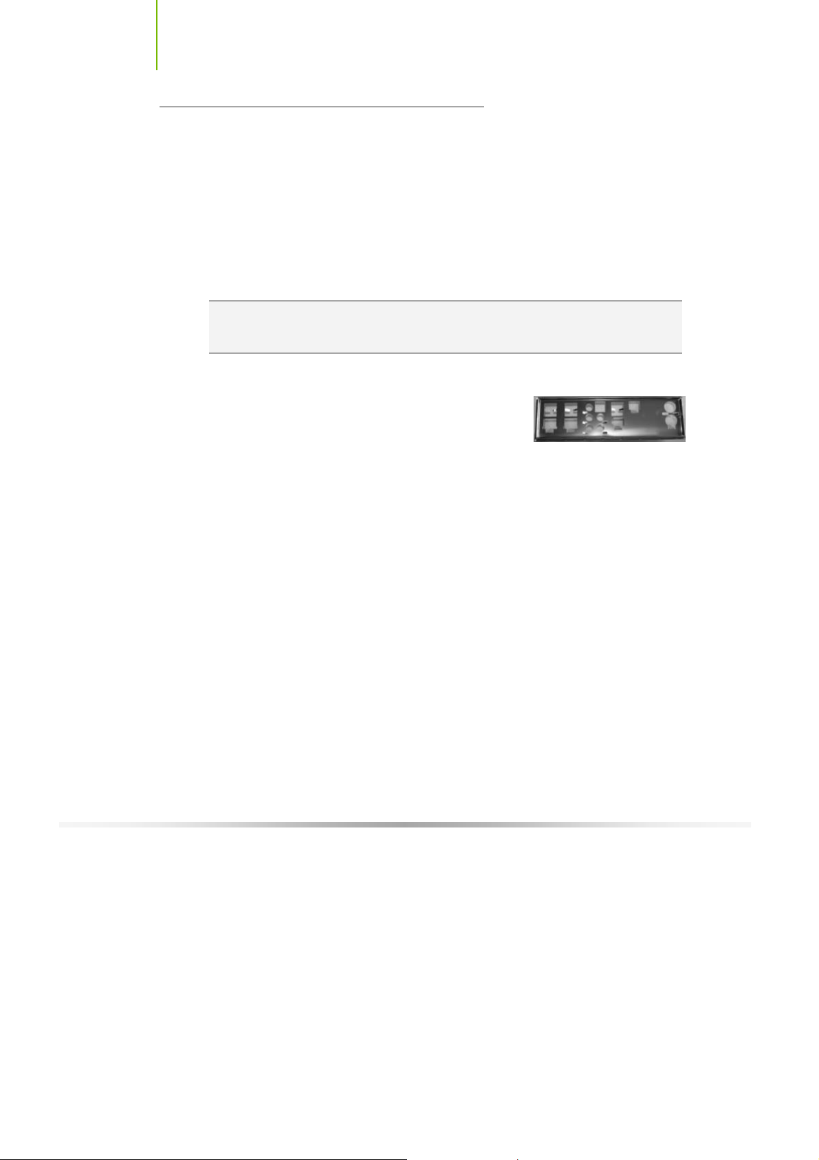
I/O Shield
Installs in the chassis to block radio frequency
transmissions, protect internet components from dust
and foreign objects and aids in proper airflow within the
chassis.
Floppy Cable
U sed to attach a floppy driv e to the motherboard.
SATA P ower Cable (Q ty 4)
USB 2.0 4-Port C able (O ptional)
Prov ides four additional USB ports to either the front or
back panels of the chassis.

Installing and C onfiguring the TF680i SLI D eluxe Motherboard
SATA S ignal Cable (Q ty 4)
Used to support the Serial ATA protocol and each one
connects a single driv e to the motherboard
IDE-ATA 133 HDD Cable
SLI C onnector
U sed to connect two graphic cards installed in the x16
PCI E xpress slots in an SLI configuration.
U ser’s Manual
Setup CD
TF680i SLI Deluxe
Motherboard
10
The TF680i SLI Deluxe Motherboard with the nForce 680i SLI chipset is a PCI
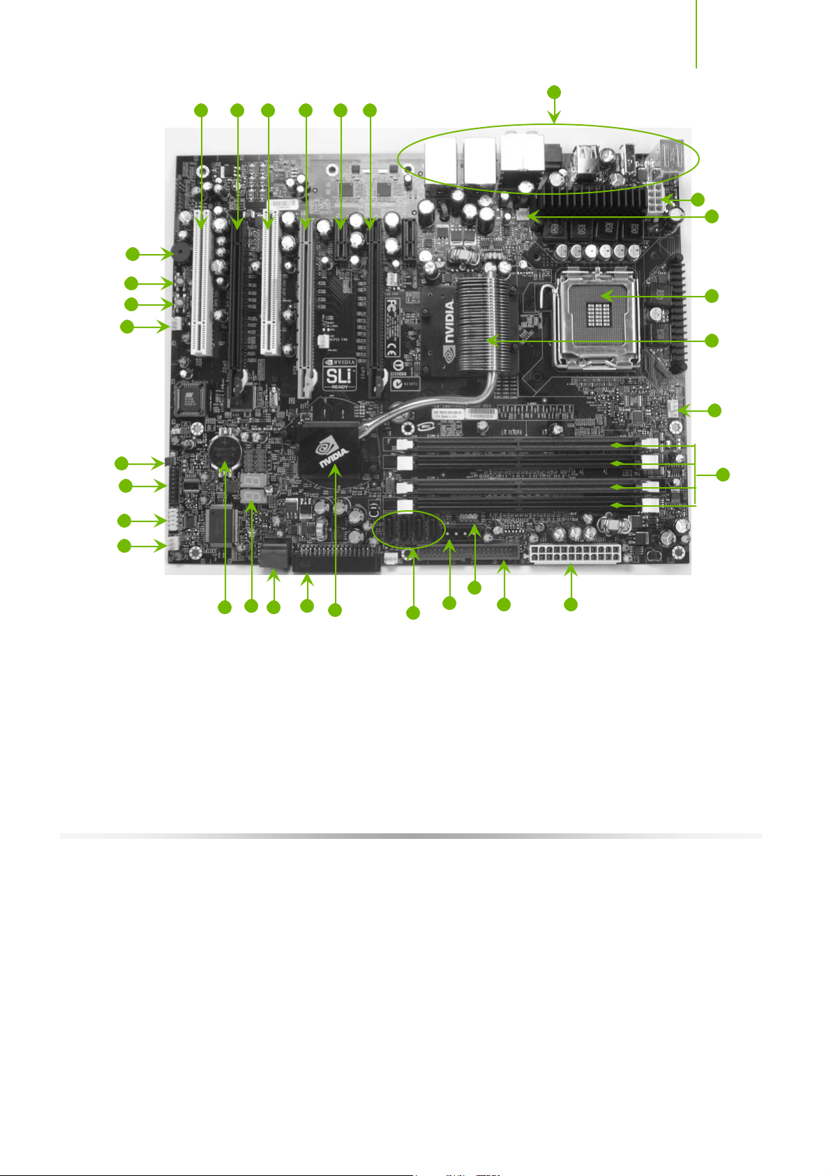
Express, SLI-ready motherboard. Figure 1 shows the motherboard and Figures
2 shows the back panel connectors.
Unpacking and Parts Description
17
16
21
20
19
18
22 23 22 24 25 23
26
27
29
1
2
3
4
15
7
12
11
10
13
14
1. CPU Socket 10. NVIDIA MC P 19. Power o/of f s witc h
2. NVIDIA SPP with passive heat sink 11. Floppy drive connector 20. Reset switch
3. C PU fan c onnec t or 12. Two Ser i al - A T A connectors 21. On-board s peaker
4. DDR DIMM Slots 0 - 3 13. LED POST codes 22. PCI s lots
5. 24-pin ATX Power C onnec t or 14. Motherb oard bat tery 23. PCI Expres s x16 s lots (SLI)
6. FDD Con nec t or 15. Seri al c onnec tor 24. PCI Expres s x16 s lots (Graphic s
7. Front panel connector 16. LPC connector (deb ug) 25. PCI Expr es s x 1 s lot
8. AUX PEX Power connector 17. Clear CMOS 26. Backpanel connectors (Figure 2)
9. Serial- ATA connectors 18. 27. 8-pin ATX_12V pow er connector
8
9
6
5
Expa nsi on)
Figure 1. TF680i SLI Deluxe Motherboard Layout
11
Installing and C onfiguring the TF680i SLI D eluxe Motherboard
1
2 3
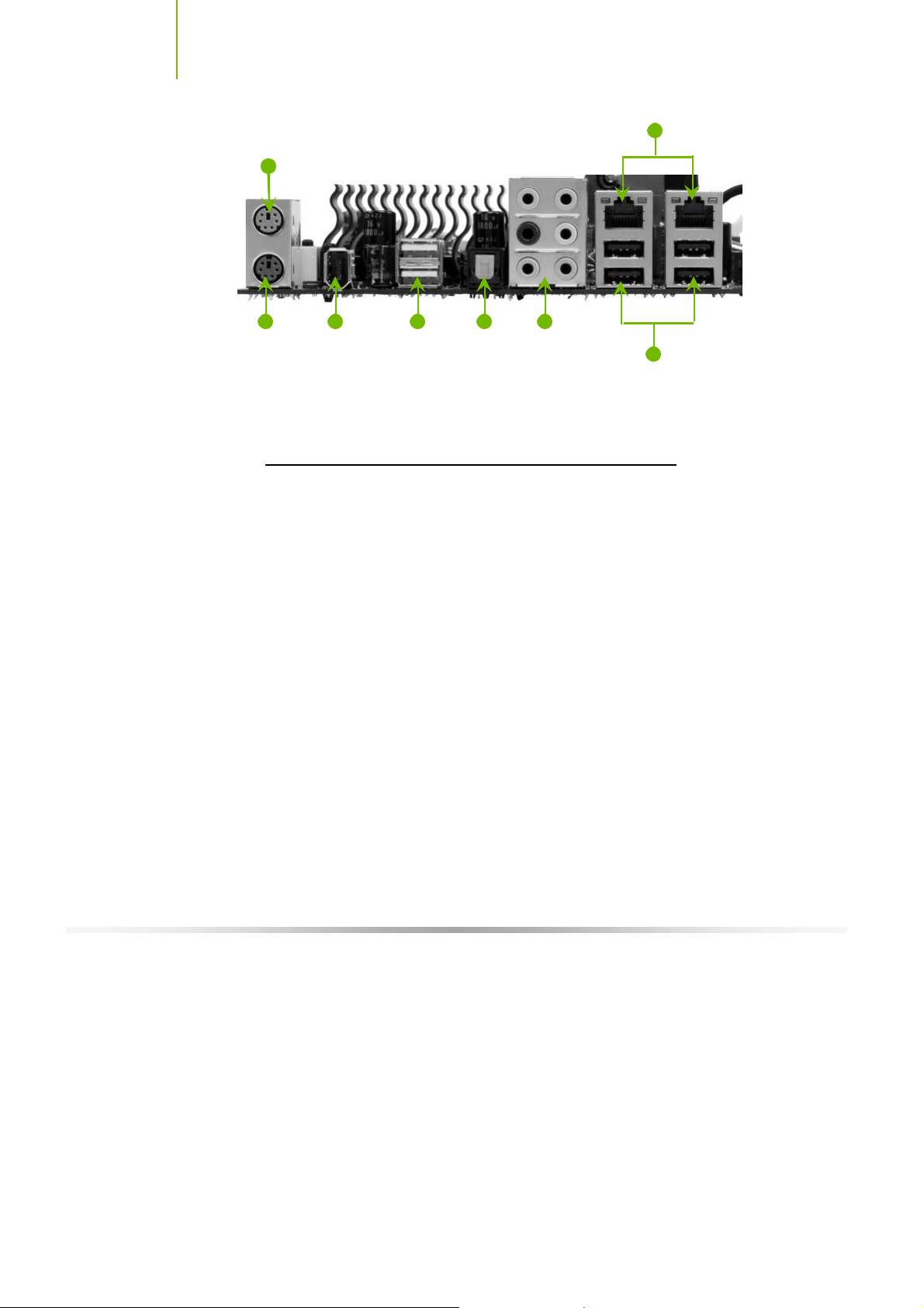
1. PS /2 Mouse Port
2. PS /2 Key board P ort
3. 1394a (F irew ire) port
4. USB 2.0 ports
5. SPDIF output
6. P ort 2-C hannel 4-C hannel 6-C hannel/8-C hannel
Blue Line-In Line-In Line-In
Green Line-O ut F ront Speaker Out Front Speaker Out
Pink Mic In Mic In Mic In
O range Center/Subwoofer
Black Rear Speaker Out Rear Speaker Out
Grey
7. USB 2.0 P orts
8. Lan Ports w ith LEDs to indicate status.
• Yellow/Light Up/Blink = 10 Mbps/Link/Activity
• Yellow and Green/Lig ht Up/B l ink = 100 Mbps /li nk/Activity
• Green/Li g ht Up/B link = 1000 Mbps /L ink/Ac t i vit y
4
5 6
8
7
12
Figure 2. Chassis Backpanel Connectors

13
This section will guide you through the installation of the motherboard. The
topics covered in this section are:
Preparing the motherboard
¾ Installing the CPU
¾ Installing the CPU fan
¾ Installing the memory
Installing the motherboard
Connecting cables and setting switches
Safety Instructions
Hardware Installation
To reduce the risk of fire, electric shock, and injury, always follow basic
safety precautions.
Remember to remove power from your computer by disconnecting the
AC main source before removing or installing any equipment from/to the
computer chassis.
Installing and C onfiguring the TF680i SLI D eluxe Motherboard
Preparing the Motherboard
The motherboard shipped in the box does
need to purchase a CPU, a CPU fan assembly, and memory to complete this
installation.
Installing the CPU
Be very careful when handling the CPU. Make sure not to bend or break any
pins on the back. Hold the processor only by the edges and do not touch the
bottom of the processor.
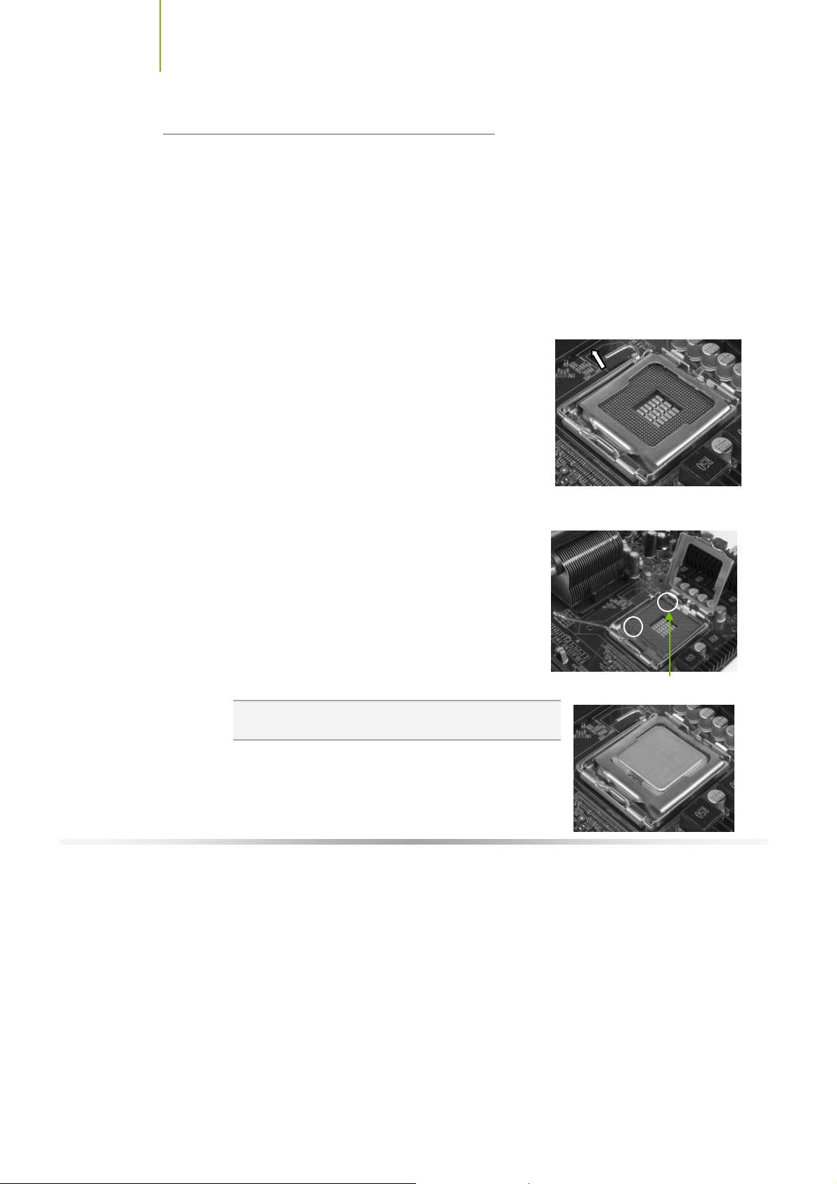
Use the following procedure to install the CPU onto
the motherboard.
1. Unhook the socket lever by pushing down and away
from the socket.
2. Lift the load plate. There is a protective socket
cover on the load plate to protect the socket when
there is no CPU installed.
3. Remove the protective socket cover from the load plate.
4. Remove the processor from its protective cover,
making sure you hold it only by the edges.
It is a good idea to save the cover so that
whenever you remove the CPU, you have a safe
place to store it.
5. Align the notches in the processor with the
notches on the socket.
6. Lower the processor straight down into the socket
with out tilting or sliding it into the socket
Note : Make sure the CPU is fully seated and level in the
socket.
not
contain a CPU or memory. You
Al i gn notches w i t h
notc hes on the C PU
14
7. Close the load plate over the CPU and press down
while you close and engage the socket lever.
H ardware Installation
Installing the CPU Fan
There are many different fan types that can be used with this motherboard.
Follow the instruction that came with you fan assembly. Be sure that the fan
orientation is correct for your chassis type and your fan assembly.
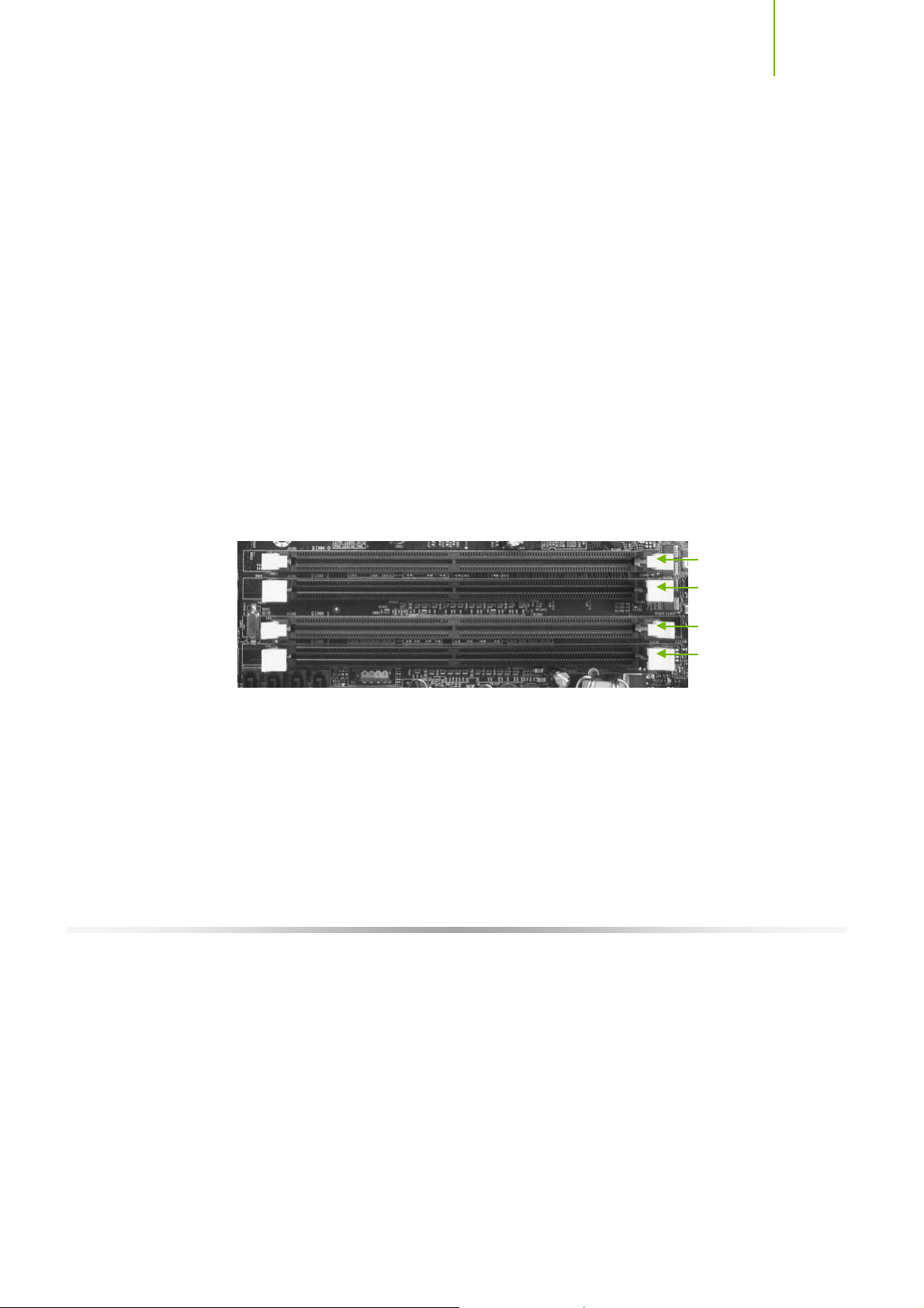
Installing Memory DIMMs
Your new motherboard has four 1.8V 240-pin slots for DDR2 memory. These
slots support 256 Mb, 512 Mb and 1 Gb DDR2 technologies for x8 and x16
devices. They also support dual channel DDR2 memory technology up to
10.7GB/s. There must be at least one memory bank populated to ensure
normal operation. Use the following the recommendations for installing
memory.
One DIMM: Install into slot 0. You can install the DIMM into any slot,
however, slot 0 is preferred.
Two DIMMs: Install into either slots 0 and 1 or 2 and 3. The idea is to not
have the DIMMs in adjacent slots.
Fou r DIMMS: Inst all into slots 0, 1, 2, and 3.
CPU side
DIMM Slot 0
DIMM Slot 2
DIMM Slot 1
DIMM Slot 3
Card-edge s ide
Use the following procedure to install memory DIMMs into the slots on the
motherboard. Note that there is only one gap near the center of the DIMM slot.
This slot matches the slot on the memory DIMM to ensure the component is
installed properly.
1. Unlock a DIMM slot by pressing the module clips outward.
2. Align the memory module to the DIMM slot, and insert the module
vertically into the DIMM slot. The plastic clips at both sides of the DIMM
slot automatically lock the DIMM into the connector.
15
Installing and C onfiguring the TF680i SLI D eluxe Motherboard
Installing the Motherboard
The sequence of installing the motherboard into the chassis depends on the
chassi s you are usin g and if you ar e replac ing an e xi sting motherboard or
working with an empty chassis. Determine if it would be easier to make all the
connections prior to this step or to secure the motherboard and then make all
the connections.
Use the following procedure to install the I/O shield and secure the
motherboard into the chassis.
Note : Be sure that the C PU fan ass embly has enough clearance f or the chassis
covers to lock int o place and for the expansion cards. Als o make sure the
CPU Fan assembly is aligned with the v ents on t he cov ers .
Installing the I/O Shield
The motherboard kit comes w ith an I/O shield that
is used to block radio frequency transmissions,
protects internal components from dust and foreign objects, and promotes
correct airflow within the chassis.
Before installing the motherboard, install the I/O shield from the inside of the
chassis. Press the I/O shield into place and make sure it fits securely. If the
I/O shield does not fit into the chassis, you would need to obtain the proper
size from the chassis supplier.
Securing the Motherboard into the Chassis
Most computer chassis have a base with mounting studs or spacers to allow the
mother board to be secured to the chassis and help to prevent short circuits. If
there are studs that do not align with a mounting hole on the motherboard, it is
recommended that you remove that stud to prevent the possibility of a short
circuit.
1. Carefully place the motherboard onto the studs/spacers located inside the
chassis.
2. Align the mounting holes with the studs/spacers.
3. Align the connectors to the I/O shield.
16

H ardware Installation
4. Ensure that the fan assembly is aligned with the chassis vents according to
the fan assembly instruction.
5. Secure the motherboard with a minimum of eight-to-ten screws.
Connecting Cables and
Setting Switches
This section takes you through all the connections and switch settings necessary
on the motherboard. This will include:
Power Connections
¾ 24-pin ATX power (
¾ 8-pin ATX 12V power (
¾ Auxiliary power for graphics (
Internal Head ers
¾ Front panel
¾ IEEE 1394a
¾ USB Headers
¾ Audio
¾ Spe aker
¾ COM
FDD
ID E
Seri al ATA II
Chassis Fans
Rear panel USB 2.0 Adapter
Expansion slots
CMOS jumper settings
PWR1)
PWR2)
PWR3)
See Figure 1 on page 11 to locate the connectors and jumpers referenced in the
fo llow ing proc edure .
17

Installing and C onfiguring the TF680i SLI D eluxe Motherboard
Power Connections
This motherboard requires an ATX power supply. To support a PCI Express
motherboard wi th the addi tion of d ual graphics car ds using NVIDIA SLI
technology, you are going to need a minimum of a 500W power supply. Make
sure you have enough power to cover all the expansion cards you will be
instal lin g. To dete rmin e w hat yo u pow er requirem en ts are fo r your specif ic
configuration, refer to www.slizone.com
24-pin AT X Power (PWR1)
PWR1 is the main power supply connector located along the edge of the board
next to the DIMM slots. Make sure that the power supply cable and pins are
properly aligned with the connector on the motherboard. Firmly plug the power
supply cable into the connector and make sure it is secure.
Figure 3. PWR1 Motherboard Connector
.
PWR1 connector
Plug pow er c abl e
from system power
supply t o PWR1
18
Table 1. PWR1 Pin Assignments
Connector Pin Signal Pin Signal
24 13
12 1
1 +3.3V 13 +3.3V
2 +3.3V 14 -12V
3 GND 15 GND
4 +5V 16 PS_O N
5 GND 17 GND
6 +5V 18 GND
7 GND 19 GND
8 PWRO K 20 RSVD
9 +5V _A UX 21 +5V
10 +12V 22 + 5V
11 +12V 23 + 5V
12 +3.3V 24 GND

H ardware Installation
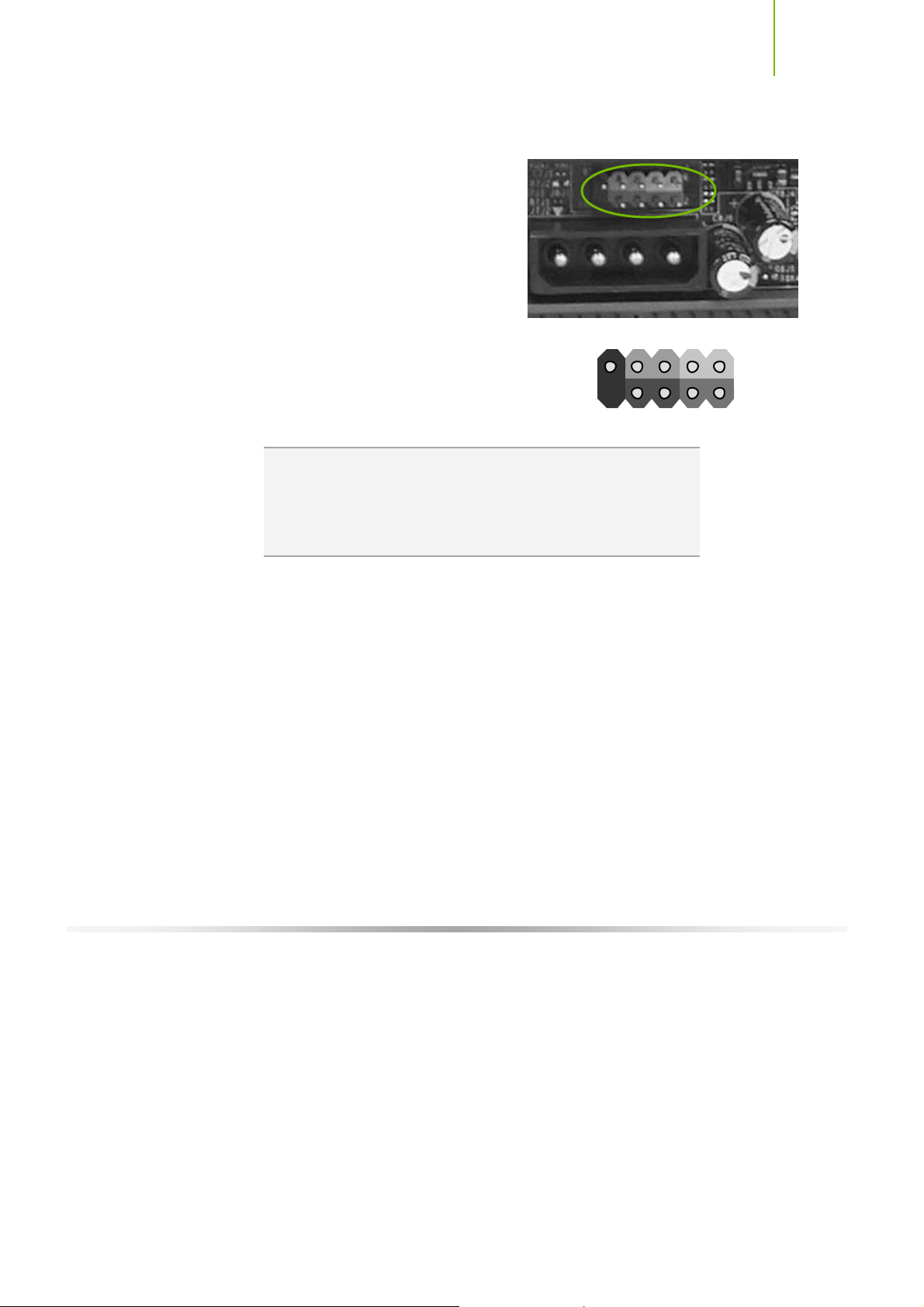
8-pin AT X 12V Power (PW R2)
PWR2, the 8-pin ATX 12V power connection, is used to provide power to the
CPU. Align the pins to the connector and press firmly until seated.
5
8 4
1
GND 12V
Connec t a four-pin
power pl ug t o pins
1, 2, 5, a nd 6.
5
1
It i s strongly recommended that you use an 8-pin ATX 12V
power supply; however, if you have a four-pin power supply,
plug the connector to pins 1, 2, 5, and 6 as shown.
Auxiliary Power for Gra phics (PWR3)
The PWR3 connector is an auxiliary power connection for graphics cards.
Exclusive power for the graphics card provides better graphics performance.
19
+5V GND
GND +1.2

Installing and C onfiguring the TF680i SLI D eluxe Motherboard
S
A
Connecting IDE Hard Disk Drives
The IDE connector supports Ultra ATA 133/100/66 IDE hard disk drives.
1. Connect the blue connector (the cable end with a single connector) to the
motherboard.
2. Connect the black connector (the cable with the two closely spaced black
and gray connectors) to the Ultra ATA master device.
3. Connect the gray connector to a slave device.
If you install two hard disk drives, you must configure the second drive as a
slave device by setting its jumper accordingly. Refer to the hard disk
documentation for the jumper settings.
Note : If an ATA-66/100 disk driv e and a disk drive using any other IDE transf er
protocol are attached to the same cable, the max imum transfer rat e between
the drives may be reduced to that of the slowest driv e.
Connecting Serial ATA Cables
TA 5
SAT A 6
20
The Serial ATA II connector is used to connect the Serial ATA II device to the
motherboard. These connectors support the thin Serial ATA II cables for
primary storage devices. The current Serial ATA II interface allows up to
300MB/s data transfer rate.
There are six serial ATA connectors on the motherboard that support RAID 0,
RAID 1, RAID 5, RAID 0+1 and JBOD configurations.
SAT A 4 SATA 2
SATA 3 SATA 1
1. Connect the locking cable end to the
motherboard connector.
2. Connect the end without the lock to the drive.
GND GND GND
TX+ RX+
TX- T X-
H ardware Installation
Connecting Internal Headers
Front Panel Header
The front panel header on this
motherboard is one connector used to
connect the following four cables:
PWRLED
Attach the front panel power LED
cable to these two pins of the connector.
The Power LED indicates the system’s status.
When the system is in S0 status, the LED is
on. When the system is in S1, S3, S4, S5
status, the LED is off.
Note : The power LED cable in s ome chassis is a three pin
connector with the pins installed in positions 1 and 3. If y our
chassis has a three pin c onnector, y ou will need t o remov e
pin 3 and put it into posit ion 2 or y ou can us e a pair of
scissors to cut out position 2. Most chassis come with a two
pin connector.
No
Connec t
10
HD_LED
RESET + -
9
PWRSW + -
Blank
PWRLED
1
2
PWRSW
Attach the power button cable from the case
to these two pins. Pressing the power button
on the front panel turns the system on off rather than using the power
supply button.
HD_LED
Attach the hard disk drive indicator LED cable to these two pins. The HDD
indicator LED indicates the activity status of the hard disks.
RESET
Attach the Reset switch cable from the front panel of the case to these two
pins. The system restarts when the
21
RESET switch is pressed.

Installing and C onfiguring the TF680i SLI D eluxe Motherboard
Table 2. Front Panel Header Pins
Pin Signal In/Out Description
HD_LED
PWRLED
RESET
PWRSW
No Connect
Empty
1 HD_ PWR Out Hard disk L ED pull- up t o + 5V
3 HDA# Out Hard dis k active LED
2 HDR_B LNK_ GR N Out Front panel gree n l i ght
4 HDR_BLNK_YEL Out Front panel yellow light
5 GND Groun d
7 FP_RE SET# In Res et switch
6 SWIT CH_ON# In Power sw itch
8 GND Groun d
9
10
IEEE 1394a (Optional)
The IEEE 1394 expansion cable bracket( optional) is provided in the box but if
you do not require the additional external connections, you do not need to
install it.
22
1. Secure the bracket to either the front or rear panel of your chassis (not all
chassis are equipped with the front panel option).
2. Connect the two ends of the cables to the IEEE 2394 connectors on the
motherboard.
Table 3. IEEE 1394a Connector Pins
Connector Pin Signal
IEEE 1 394 a C onnec t or
10
8
6
4
2
9
7
5
3
1
1 TPA+
2 TPA-
3 GND
4 GND
5 TPB+
6 TPB-
7 +12V
8 +12V
9 Empt y
10 GND

H ardware Installation
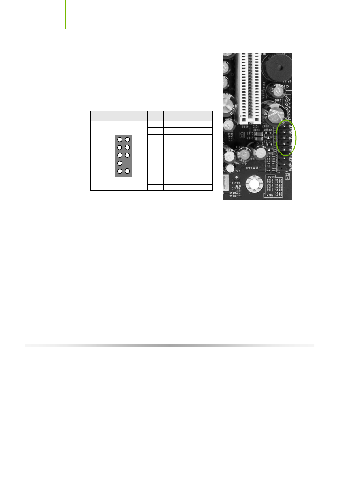
USB Headers
This motherboard contains four (4) USB 2.0
ports that are exposed on the rear panel of the
chassi s. The moth erboard al so contai ns two
10-pin internal header connectors onboard that
can be used to connect an optional external
bracket containing four (4) more USB 2.0
ports.
1. Secure the bracket to either the front or
rear panel of your chassis (not all chassis
are equipped with the front panel
option).
2. Connect the two ends of the cables to
the USB 2.0 headers on the
motherboard.
Table 4. USB 2.0 Header Pins
Connector Pin Signal Pin Signal
USB 2.0 Hea der C onn ector
9
7
5
3
1
10
8
6
4
2
1 5V_DUA L 2 5V_DUA L
3 D- 4 D-
5 D+ 6 D+
7 GND 8 GND
9 Empt y 10 No Connec t
23
Installing and C onfiguring the TF680i SLI D eluxe Motherboard
Audio
The audio connector supports HD audio standard
and pro vide s two kind s of audi o outp ut cho ices: the
Front Audio, the Rear Audio. The front Audio
supports re-tasking function.
Table 5. Front Audio Connector
Connector Pin Signal
Front A udio C onn ect or
1
3
5
7
9
2
2
4
6
8
10
1 POR T 1_L
2 AUD_G ND
3 POR T 1_R
4 PRECENC E_J
5 POR T 2_R
6 SENSE1_RET UR N
7 SENSE_S END
8 Empt y
9 POR T 2_L
10 SENSE2_RET UR N
24

H ardware Installation
Fan Connections
There are two fan connections, the system fan and the CPU fan. The fan speed
can be detected and viewed in the
Both fans are automatically turned off after the system enters S3, S4 and S5
mode.
PC Health Status section of the CMOS Setup.
Note that the CPU fan cable can be
either a 3- pi n or a 4- pi n c onnector.
Connec t a 3-pi n c onnec t or t o pins 1, 2,
and 3 on the motherb oard connector.
CPU Fan Connector
4 3 2 1
GND SENSE
PWR CONTROL
25
The nFor c e SPP a nd MCP have a pas s ive
heat sink t hat draws heat from the chips.
You c an i ns tal l a fan ont o t he SPP heat
sink that helps to cool the chips. Hook the
fan over the SPP heat sink. Use the two
screws to secure the fan to the SPP. Plug
the cable into the fan connector.
SPP Con nect or
3 2 1
GND
Secure fan assembly using two screws
+12V
SENSE

Installing and C onfiguring the TF680i SLI D eluxe Motherboard
COM1 (Optional)
The motherboard kit pro vides an additional seri al COM head er for you r
machine. Connect one side of a switching cable to the header and then attach
the serial COM device to the other side of the cable.
FDD Connector
The motherboard supports a standard 360K, 720K, 1.2M, 1.44m, and a 2.88M
fl oppy disk dr ive (FDD).
Speaker
The speaker connector is used to connect the chassis speakers to the
motherboard.
26

H ardware Installation
Expansion Slots
The TF680i SLI Deluxe Motherboard contains six expansion slots, four PCI
Express slots and two PCI slots. For a full list of PCI Express x16 graphics card
supported by this motherboard, go to www.ncvidia.com/estore
1 3
.
124 2
1 - PCI Express
2 - x16 PCI Expr es s
SLI connector
3 - x16 PCI Expr es s
(Gr aphi c s expans ion)
4 - x 1 PC I C onnec tor
Figure 4. Expansion Slots
PCI Slots
The two PCI slots support many expansion cards such as a LAN card, USB
card, SCSI card and other cards that comply with PCI specifications. When
installing a card into the PCI slot, be sure that it is fully seated. Secure the card’s
metal bracket to the chassis back panel with the screw used to hold the blank
cover.
27

Installing and C onfiguring the TF680i SLI D eluxe Motherboard
PCI Express x1 Slot
There is one PCI Express x1 slot that is designed to accommodate less
bandwidth-intensive cards, such as a modem or LAN card. The x1 slot provides
250 MB/sec bandwidth.
PCI Express x16 Slots
These two PCI Express x16 slots are reserved for graphics or video cards. The
bandwidth of the x16 slot is up to 4GB/sec (8GB/sec concurrent). The design
of this motherboard supports dual PCI-Express graphics cards using NVIDIA’s
SLI technology with multiple displays.
When installing a PCI Express x16 card, be sure the retention clip snaps and
locks the card into place. If the card is not seated properly, it could cause a
short across the pins. Secu re the card’s metal bracket to the chassis back panel
with the screw used to hold the blank cover.
To configure for SLI, follow the instructions that come with the SLI kit (the kit
is purchased separately from the motherboard).
Jumper Settings
The motherboard contains a 3-pin BIOS configuration jumper that enables all
board configurations to be done in the BIOS Setup program.
The silk screen on the motherboard shows a ∆ next to pin 1.
Clear CMOS Jumper: CLR_CMOS
The motherboard uses the CMOS RAM to store all the set parameters. The
CMOS can be cleared by removing the CMOS jumper.
Use the following procedure to clear CMOS:
1. Turn off the AC power supply and connect pins 1 and 2 together using the
jumper cap.
2. Return the jumper setting to normal (pins 2 and
3. Together with the jumper cap).
4. Turn the AC power supply back on.
28

29
Configuring the BIOS
This section discusses how to change the system settings through the BIOS
Setup menus. Detailed descriptions of the BIOS parameters are also provided.
This section includes the following information:
Enter BIOS Setup
Main Menu
Stand ard CMOS Features
Advanced BIOS Features
Advanced Chipset Features
Integrated Peripherals
Power Management Setup
PnP/PCI Configurations
System Monitor

Installing and C onfiguring the TF680i SLI D eluxe Motherboard
Enter BIOS Setup
The BIOS is the communication bridge between hardware and software.
Correctly setting the BIOS parameters is critical to maintain optimal system
performance.
Use the following procedure to verify/change BIOS settings.
1. Pow er on the com puter ,
2. Press the Del key when the following message briefly displays at the bottom
of the screen during the Power On Self Test (POST).
Pre ss F1 to c ont in ue, D EL to en te r Set up.
Pressing De l takes you to the Phoenix-Award BIOS CMOS Setup Utility.
Note : It is s trongly recommended t hat y ou do not change the default BIOS
settings. Changing some settings could damage y our c omputer.
Main Menu
The main men u allo ws y ou to se lect from the li st of setup fu nction s and tw o
exit choices. Use the
options or press
keys to position the selector in the option you choose. To go back to the
previous menu, press
Note : Note that on the BIOS screens all data in whit e is f or inf ormat ion only, data in
y ellow is changeable, data in blue is non-changeable, and data in a
red box is highlight ed for selection.
30
Page Up and Page Down keys to scroll through the
Enter to display the associated submenu. Use the arrow
Esc.

Configuring the BIOS
Phoenix – Awar dB IOS CMOS Setup Utility
` Standard CMOS Features
` Advanced BIOS Features
` Adv ance d Chip set Fe atures
` Integrated Peripherals
` Power Management Setup
` PnP/PCI Configurations
Es c : Qu it
F10 : Save & Exit Setup
Ti me , Date, Ha rd D is k Type ..,
NVIDI A Li nkBoost ™ - Not Det ected SLI- Rea dy memor y - Dis able d
` System Monitor
Load Defaults
Set Pa ss word
Save & Exit Setup
Exit Without Saving
: Select Item
Figure 5. BIOS CMOS Setup Utility Main Menu
Standard CMOS Features
Use this menu to set up the basic system configuration.
Advanced BIOS Features
Use this menu to set up the advanced system features and boot sequence.
Advanced Chipset Features
Use this menu to optimize system performance and configure clocks,
voltages, memory timings, and more.
Integrated Peripherals
Use this me nu to set up on board pe riph er als suc h as IDE, RA ID, USB ,
LAN, and MAC control.
Power M anagement Setup
Use this menu to configure power management, power on, and sleep
features.
PnP/PCI Configurations
Use this menu to modify the system’s Plug-and-Play and PCI configurations.
31

Installing and C onfiguring the TF680i SLI D eluxe Motherboard
System Monitor
Use this menu to monitor the real-time system status of your PC, including
temperature, voltages, and fan speed.
The following items on the CMOS Setup Utility main menu are commands
rather than submenus:
Load Defaults
Use this command to load the NVIDIA LinkBoost technology settings for
LinkBoost-enabled systems. Load default system settings for standard
systems.
Set Password
Use this command to set, change, and disable the password used to access
the BIOS menu.
Save & Exit Setup
Use this command to save settings to CMOS and exit setup.
Ex it Without Saving
Use this command to aban don all setting changes and exi t setup.
The following two items on the CMOS Setup Utility main menu are status
indicators:
32
NVI D IA LinkBoost (Status indication at bo t tom of screen)
This status i ndicator is displayed at the bottom of the BIOS screen and
consists of the following remarks:
¾ Detected: System detects LinkBoost-capable components.
¾ Not Detected: The LinkBoost components are not detected.
SLI-Ready Memory (Status indication at bottom of screen)
This status i ndicator is displayed at the bottom of the BIOS screen and
consists of the following remarks:
¾ Enabled: SLI-Ready memory is detected and enabled.
¾ Disabled: SLI-Ready memory is detected but disabled.
¾ Not Detected: SLI-Ready memory is not detected.

Configuring the BIOS
Standard CMOS Features
Menu
The Standard CMOS Features menu is used to configure the standard CMOS
information, such as the date, time, HDD model, and so on. Use the
and Page Down keys to scroll through the options or press Enter to display the
sub-menu. Use the arrow keys to position the selector in the option you
choose. To go back to the previous menu, press
The inf ormatio n show n in Item Hel p co rr espon ds to th e op tion hi gh lig h ted.
Page Up
Esc.
Phoenix – Awar dB IOS CMOS Set up Uti lity
Date (mm:dd:yy) Sat, Jul 01 2006
Time (hh:mm:ss) 12 : 48: 23
` IDE Ch an nel (. ) Mast er [None]
` IDE Ch an nel (. ) Slav e [None]
` SATA Channel 1 Master [None]
` SATA Channel 2 Master [None]
` SATA Channel 3 Master [None]
` SATA Channel 4 Master [None]
` SATA Channel 5 Master [None]
` SATA Channel 6 Master [None]
Driv e A [1.44, 3.5 in.]
Halt On [All , But Keyboard]
Base Memory 640K
Extended Memory 1047552K
Tota l Me mory 10 48 576K
:Move Enter :Selec t +/-/PU/P D:Value F1 0:Sav e ESC :Exit F1:Genera l Help
F5: Prev ious Values F7:Defa ults
Standard CMOS Features
Item Help
Main Level `
Change the day, month,
year and century
Figure 6. Standard CMOS Features Menu
Note : Note that all data in whit e is for informat ion only, data in yellow is c hangeable,
data in blue is non-c hangeable, and data in a red box is highlighted for
selection.
33

Installing and C onfiguring the TF680i SLI D eluxe Motherboard
Date and Time
Using the arrow keys, position the cursor over the month, day, and year. Use
the
Page Up and Page Down keys to scroll through dates and times. Note that
the weekday (Sun through Sat) cannot be changed. This field changes to
correspond to the date you enter. Note that the hour value is shown in a
24-hour clock format. Time is represented as hour : m inute : se cond.
Date ( mm :dd:yy) Sat , Jul 01 2 006
Time ( hh :mm:ss) 14 : 48: 4 3
IDE Channel and SATA Channel
Use these functions to detect and configure the individual IDE and SATA
channels. Select a channel and press
` IDE Ch an nel (. ) Mast er [None]
` IDE Ch an nel (. ) Slav e [None]
` SATA Channel 1 Master [None]
` SATA Channel 2 Master [None]
` SATA Channel 3 Master [None]
` SATA Channel 4 Master [None]
` SATA Channel 5 Master [None]
` SATA Channel 6 Master [None]
IDE Auto-Detect [Press Enter]
Extended IDE Drive [None}
Access Mode Auto
Capacity 0 MB
Cylinder 0
Head 0
Precomp 0
Landing Zone 0
Sector 0
Press ENTER to display
SAT A Channel s ub-menu
Enter to display the IDE/SATA sub-menu.
Press ENTER to display
IDE Channel sub-menu
ID E HD D Auto-Detect [Press Enter]
ID E Ch annel 0 Sl av e [Manual}
Access Mode [CHS]
Capacity 0 MB
Cylinder [ 0]
He ad [ 0]
Precomp [ 0]
Landing Zone [ 0]
Sector [ 0]
34

Configuring the BIOS
Press Enter to auto-detect IDE and SATA channels in the system. Once the
channel is detected, the values for Capacity, Cylinder, Heads, Precomp, Landing
Zone, and Sector are automatically filled in.
None
There is no HDD installed or set.
Auto
The system can auto-detect the hard disk when booting up.
Manual
When you set the channel to [Manual ] an d ch ange Acces s Mod e to [CH S] ,
you can then enter the number of cylinders, heads, Precomp, landing zone,
and sector. You can manually enter the values or you can press
Enter to
display a window that tells you the min and max values.
ID E HD D Auto-Detect [Press Enter]
ID E Ch annel 0 Sl av e [Manual}
Access Mode [CHS]
Capacity 0 MB
Cylinder .....0
He ad [ 0]
Precomp [ 0]
Landing Zone [ 0]
Sector [ 0]
The BIOS supports the following HDD
Access Modes:
¾ CHS
For HDD less than 528 MB.
¾ LBA
For HDD greater than 528 MB and
Press ENTER to display sub-menu
or ent er num ber m anual ly
Cylinder
Min= 0
Max=65535
Key in a DEC number :
:Move ENTER:A ccept ESC:Abor t
supporting LBA (Logical Block
Addressing).
¾ Large
For HDD greater than 528 MB bu t not supporting LBA.
¾ Auto
Recommended mode.
35

Installing and C onfiguring the TF680i SLI D eluxe Motherboard
Drive A
The Drive A option allows you to select the kind of FDD to install.
Options are:
Driv e A [1.44, 3.5 in.]
Halt On [All , But Keyboard]
None
360K, 5.25 in.
1.2M, 5.25 in.
720K, 3.5 in.
1.44M, 3.5 in.
2.88M, 3.5 in.
Use the
through the options or press
the sub-menu. Use the arrow keys to
position the selector in the option you choose. Press
changes and return to the Stan d ard CMOS Featu re s menu .
Page Up and Page Down keys to scroll
Enter to di spl ay
Press ENTER to display sub-menu
Drive A
None ..... [ ]
360K, 5.25 in. ..... [ ]
1.2M, 5.25 in. ..... [ ]
720K, 3.5 in. ..... [ ]
1.44M, 3.5 in. ..... [ ]
2.88M, 3.5 in. ..... [ ]
:Move ENTER:A ccept ESC:Abor t
Enter to accept the
Halt On
Halt On determines whether or not the computer stops if an error is detected
during power on. Use the
options or press
to position the selector in the option you choose. Press
changes and return to the Stan d ard CMOS Featu re s menu .
Driv e A [1.44, 3.5 in.]
Halt On [All , But Keyboard]
All Errors
No Errors
All, But Keyboard
36
Page Up and Page Down keys to scroll through the
Enter to di spl ay th e Halt On sub-menu. Use the arrow keys
Whenever the BIOS detects a nonfatal
error, the system stops and prompts you.
System boot does not stop for any
detected errors.
System boot does not stop for keyboard
errors, but does stop for all other errors.
Enter to accept the
Press ENTER to display sub-m enu
Halt On
All Errors ..... [ ]
No Errors ..... [ ]
Al l , Bu t Keyboa rd .. ... [ ]
Al l , Bu t Disket te .. ... [ ]
Al l , Bu t Disk/K ey .. ... [ ]
:Move ENTER:A ccept ESC:Abor t

Configuring the BIOS
All, But Diskette
All, But Disk/Key
Memory
These settings are displa y -only valu es that are determined by the BIOS POST
(Pow er-On Self Test).
Base Memory
Extended Memory
Total Memory
The system boot does not stop for a diskette error but will stop for all other
errors.
The system boot does not stop for a keyboard or disk error, but will stop for
all other errors.
Base Memory 640K
Extended Memory 1047552K
Tota l Me mory 1048576K
BIOS POST determines the
amount of base (or conventional) memory installed in the system.
BIOS determines how much extended memory is present during the POST.
This value represents the total memory of the system.
37

Installing and C onfiguring the TF680i SLI D eluxe Motherboard
Advanced BIOS Features
Access the Advanced BIOS Features menu from the CMOS Utility Setup
sc ree n. Use th e
press
Enter to display the sub-menu. Use the arrow keys to position the
selector in the option you choose. To go back to the previous menu, press
Note : The options that hav e associated sub-menus are designated by a `, which
precedes the option. Press En ter to display t he sub-menus.
Page Up and Page Down keys to scroll through the options or
Esc.
Phoenix – Awa rdBIOS CMOS Setup Util ity
` Remo va ble De vice P ri orit y [Press Enter]
` Hard Disk Boot Priority [Press Enter]
` Netw or k Boot P ri orit y [Press Enter]
CPU In te rnal C ac he [Enabled]
Quic k Po wer On S el f Te st [Enabled]
Firs t Bo ot D evic e [Removable]
Seco nd B oo t Devi ce [CDROM]
Thir d Bo ot D evic e [Hard Disk]
Boot Other Device [Enabled]
Boot Up Nu mLock St at us [On]
Secu ri ty O ptio n [Setup]
APIC Mode [Enabled]
MPS Ve rs ion Cont ro l For OS [1.4]
Full Screen LOGO Show [Disabled]
:Move Enter :Selec t +/-/PU/P D:Value F1 0:Sav e ESC :Exit F1:Genera l Help
F5: Prev ious Values F7:Defa ults
Advanced BIOS Features
Item Help
Main Level `
Select Removable Boot
Device Priority
Figure 7. Advanced BIOS Features Menu
Note : Note that all data in whi t e is for information only , data in yellow is changeable,
data in blue is non-c hangeable, and data in a red box is highlighted for
selection.
38

Configuring the BIOS
p
t
Removable Device Priority
Use this option to select the priority for removable device startup. Press Enter
to see the list of removable devices in your system. Use the arrow keys to go
to the various devices. Then use the
or down in the list. To go back to the previous menu, press
+ or – keys to move the device priority up
Esc.
1. Flopp y Dis ks
Hard Disk Boot Priority
Use this option to select the priority for HDD startu p. Press Enter to see the
list of bootable devices in your system. Use the arrow keys to go to the
various devices. Then use the
down in the list. To go back to the previous menu, press
1. Ch0. : S T3 80211 0A
2. Boo
able A dd-in Ca rds
Network Boot Priority
Use this option to select the priority for network startup. Select Networ k Boo t
Pri ori ty and press Enter to view available networks. Use the arrow keys
to go to the various devices. Then use the
priority up or down in the list. To go back to the previous menu, press
1. Netwo rk 0 : <desc ription of netw ork>
2. Netwo rk 1 : <desc ri
+ or – keys to move the device priority up or
Esc.
Use the + and – keys to move the
priority of the device within the list
+ or – keys to move the device
Esc.
tion of networ k>
CPU Internal Cache
Use this option to enable or disable the CPU internal cache. Use the Page Up
and Page Down keys to scroll through the options or press Enter to display the
options in a sub-menu. Use the arrow keys to position the selector in the
option you choose.
39

Installing and C onfiguring the TF680i SLI D eluxe Motherboard
Quick Power On Self Test
Enabling this option allows the system to skip certain test while booting, which
redu ces the time ne eded to boot th e system. U se the
keys to toggle between
Enable and Di sa ble .
First/Second/Third Boot Device
Use this option to set the priority sequence of the devices booted at power on.
Use the
Enter to display the sub-menu. Use the arrow keys to position the selector
in the option you choose.
Page Up and Page Down keys to scroll through the options or press
First Boot Device
Removable ..... [ ]
Hard Disk ..... [ ]
CDROM ..... [ ]
Network ..... [ ]
Disabled ..... [ ]
:Mov e ENT ER:A cc ept ESC :A bo rt
Page Up and Page Down
Boot Other Device
With the option set to En able , the system boots from some other device if the
first/second/third boot devices fail.
Boot Up NumLock Status
This option allows you to select the power-on state of NumLock. Select On to
activate the keyboard NumL ock when the system is started. Select Off to d i sable
the
NumLock key.
40

Configuring the BIOS
Security Option
The Security Options allows you to require a password every time the system
boots or only when you enter setup. Select Setup to require a password to gain
access to the CMOS Setup screen. Select System to require a password to
access the CMOS Setup screen and when the system boots.
APIC Mode
Use this function to enable or disable the Advanced Programmable Interrupt
Controller (APIC). If you disable this option, you also disable the MPS Version
Control for OS option.
MPS Version Control For OS
Use this function to select the Multi-Processor Specification (MPS) versi on that
BIOS passes to the operating system. Use the
scroll through the options.
Page Up and Page Down keys to
Full Screen LOGO Show
This option allows you to enable or disable the display of the full-screen logo
when the system boots. Use the
between
41
Enable and Di sa ble
Page Up and Page Down keys to toggle

Installing and C onfiguring the TF680i SLI D eluxe Motherboard
Advanced Chipset Features
Select Advance d C hips et Featu re s from the CMOS Setup Utility menu and
press
Enter to display the functions of the Advanced Chipset Functions menu.
Phoenix – Awa rdBIOS CMOS Setup Util ity
Advanced Chip set Feature s
` Syst em C lo cks [Press Enter]
` FSB & Me mo ry Con fig [Press Enter]
` CPU Co nf igur atio n [Press Enter]
` System Voltages [Press Enter]
NVME M me mory t es t [Disable]
PCI Cl oc ks [Auto]
Load timing/voltage set [Press Enter]
Save timing/voltage set [Press Enter]
Syst em B IO S Cach eabl e [Disabled]
HPET Function [Enable]
NVID IA GPY E x [Enable]
Link Bo ost [Enable]
:Move Enter :Selec t +/-/PU/P D:Value F1 0:Sav e ESC :Exit F1:Genera l Help
F5: Prev ious Values F7:Defa ults
Figure 8. Advanced Chipset Features
Item Help
Main Level `
Voltage control
42

Configuring the BIOS
il i
System Clocks
Select System Clo ck s from the Advanced Chipset Features menu and press
Enter to di spl ay the System Cloc ks menu . From this me nu, y ou are ab le to
specify frequency settings, HT multipliers, and Spread Spectrum settings. Note
that in Figure 9, all of the options are listed. On the actual BIOS screen, you will
need to scroll down to see all the options.
Phoenix – Awa rdBIOS CMOS Setup Ut
System C locks
Parameters Settings Current Valce
**Frequency Settings**
CPU Freq, MHz 2933.3 2933.3
FS B Re ferenc e Cl ock, M Hz 106 6.7 1066.7
CP U Mu ltipli er [11 X] 11X
PCIe x16_1 , MHz [Auto] 100
PCIe x16_3 , MHz [Auto] 100
PCIe x16_2 , MHz [Auto] 100
SP P< ->MCP Re f Cl ock, M Hz [Auto] 100
**HT Multiplier**
nForce SPP --> nForce MCP [5 x]
nForce SPP <-- nForce MCP [5 x]
**Spread Spectrum**
CPU Spread Spectrum [UP Spread]
HT Spread Spectrum [Auto]
PCIe Spread Spectrum(SPP) [Auto]
PCIe Spread Spectrum(MCP) [Auto]
SATA Spread Spectrum [Down Spread]
:Move Enter :Selec t +/-/PU/P D:Value F1 0:Sav e ESC :Exit F1:Genera l Help
F5: Prev ious Values F7:Defa ults
Figure 9. System Clocks Menu
ty
Item Help
Main Level `
CP U fr equenc y
multiplier.
CPU core clock
= FS B Re f Clock/ 4 *
CPU Mu lt iplier
d
Note : Note that all data in whi t e is for information only , data in yellow is changeable,
data in blue is non-c hangeable, and data in a red box is highlighted for
selection.
43

Installing and C onfiguring the TF680i SLI D eluxe Motherboard
Frequency Settings
CPU Freq, MHz
This value is set by the CPU Multiplier (value cannot be changed by the user).
FSB Reference Clock. MHz
This value is set by the system (value cannot be changed by the user). To
change the SLI-Ready memory, FSB memory, and memory timing, go to the
FSB & Memory screen.
CPU Multiplier
This value changes the CPU Frequency value depending on the value you
choo se. Use th e
The options are from 6 X through 60 X.
PCIe x16_ 1, M Hz
Use the
Page Up and Page Down keys to scroll through the frequency
options for the PCI Express Bus, Slot 1 (the black slot closest to the CPU).
Note that as you go higher in value,
disabled and cannot be changed from this status.
PCIe x16_ 3, M Hz
Use the
Page Up and Page Down keys to scroll through the frequency
options for the PCI Express Bus, Slot 3 (the blue slot in the middle).
PCIe x16_ 2, M Hz
Use the
Page Up and Page Down keys to scroll through the frequency
options for the PCI Express Bus, Slot 3 (the black slot farthest from the
CPU). Note that as you go higher in value,
disabled and cannot be changed from this status.
SPP<
—
Use the
>M CP Ref Clo ck, M Hz
Page Up and Page Down keys to scroll through the frequency
options for the reference clock between the SPP chip and the MCP chip.
Note that as you go higher in value,
cannot be changed from this status.
Page Up and Page Down keys to scroll through the options.
PCIe Sp re ad Spect ru m(SPP ) is
PCIe Spre ad Spectru m( MCP) is
HT Spre ad Spectru m is disabled and
44

Configuring the BIOS
HT Multiplie r
nForce SPP
Use the
options and set the link speed from the SPP chip to the MCP chip. Values
are
[1 x] through [5 x].
nForce M CP <
Use the
options and set the link speed from the MCP chip to the SPP chip. Values
are
[1 x] through [5 x].
— —
> nForce MCP
Page Up and Page Down keys to scroll through the HT multiplier
— —
nForce SPP
Page Up and Page Down keys to scroll through the HT multiplier
Spread Spect rum
CPU Spread Spectrum
Use the
Spectrum options for the CPU. Option values are
[UP Sp re ad], and [Ce nte r Sprea d].
HT Spread Spectrum
Use the
Spectrum options for the HyperTransport. Option values are
[UP Sp re ad], and [Cen ter Spr ead]. This option reverts to Disable d
and cannot be changed when the value for SPP<—>MCP Re f Cloc k exceed s
200 MHz.
PCIe Spread Spectrum (SPP)
Use the
Spectrum options for the SPP PCIe. Option values are
[UP Sp re ad], and [Ce nte r Sprea d]. This option reverts to Disabl ed
and cannot be changed w hen the value for PCIe x16_1 exceeds 100MHz.
PCIe Spread Spectrum(MCP)
Use the
Spectrum options for the MCP PCIe. Option values are
[UP Sp re ad], and [Cen ter Spr ead]. This option reverts to Disabled
and cannot be changed w hen the value for PCIe x16_3 exceeds 100 MHz.
SATA Spread Spectrum
Use the
Spectrum options for the Serial-ATA. Option values are
[Down Sp rea d].
Page Up and Page Down keys to scroll through the Spread
[Disabled ],
Page Up and Page Down keys to scroll through the Spread
[Disable d],
Page Up and Page Down keys to scroll through the Spread
[Disabled ],
Page Up and Page Down keys to scroll through the Spread
[Disabl ed] ,
Page Up and Page Down keys to scroll through the Spread
[Disabled ] an d
45

Installing and C onfiguring the TF680i SLI D eluxe Motherboard
FSB & Memory Config
Select FSB & M emo ry C onfig from the Advanced Chipset Features menu and
press
Enter to display the FSB & Memory Config menu. This menu provides
the me ans to se t SLI-Read y m emo ry , FSB me mory , and memo ry ti min g.
Phoenix – Awa rdBIOS CMOS Setup Util ity
FSB & Me mory Config
46
Para me ters Settings Current Value
SLI- Re ady Memo ry [Disabled] Disabled
CPU Fr eq , MHz 2933.3 2933.3
CPU Mu lt iplier 11X 11X
FSB – Me mo ry C lock M od e [Auto]
x FS B (Q DR ), M Hz A ut o 1066.7
Actual FSB (QDR), MHz 1066.7
x ME M (D DR ), M Hz A ut o 800.6
A ctua l MEM (D DR ), M Hz 800. 0
` Memo ry T im in g Settin g [Press Enter]
:Move Enter :Selec t +/-/PU/P D:Value F1 0:Sav e ESC :Exit F1:Genera l Help
F5: Prev ious Values F7:Defa ults
Figure 10. FSB & Memory Config Menu
SLI-Ready Memory
Use the
Memory options. The options are:
¾ Disabled
¾ CPUOC 0%
¾ CPUOC 1%
¾ CPUOC 2%
¾ CPUOC 3%
¾ CPUOC 4%
¾ CPUOC 5%
¾ CPUOC MAX
Page Up and Page Down keys to scroll through the SLI-Ready
Item Help
Main Level ``
“CPUOC MAX” realizes
the complete optimized
memory settings when
SLI-Ready memory is
installed
Optimized memory
settings by allowing
X% CPU overclocking
CP U ov ercloc ki ng may
require manual
overvolting of the CPU
to improve system
stability

Configuring the BIOS
When you select one of the CPUOC x% op tion s, the FSB - Memory
Clock Mode is set to Unlinked and cannot be changed until SLI-
Ready Memory is set to Disable.
FSB and M emory Clock Mode
Use the
Page Up and Page Down keys to scroll through the FSB and
Me mory Clo ck Mode op tion s. The opti ons ar e:
¾ Auto
This is the optimal setting since it sets the FSB and memory speeds
automatically.
¾ Linked
When Link is selected,
FSB (QDR), MHz is changed to editable an d
the FSB speed can be entered manually. As the FSB speed is changed,
CPU Freq, MHz changes proportionally.
CPU Fr eq , MHz 2933.3 2933.3
CPU Mu lt iplier 11X 11X
FSB – Me mo ry C lock M od e [Linked]
FSB (Q DR ), M Hz [1067] 1066.7
Actual FSB (QDR), MHz 1066.7
x ME M (D DR ), M Hz A ut o 800.6
A ctua l MEM (D DR ), M Hz 800. 0
¾ Unlinked
When Unlink is selected,
FSB (QDR), MHz and MEM (DDR), MHz
are ch an ged to edi table and th e FSB an d mem ory sp eeds can be entered
manually. As the FSB speed is changed,
CPU Freq, MHz chan g e s
proportionally.
FSB – Memory Clock Mode [Linked]
FSB (Q DR ), M Hz [1067] 1066.7
Actual FSB (QDR), MHz 1066.7
ME M (D DR), M Hz [1067] 800.6
A ctua l MEM (D DR ), M Hz 800. 0
FSB (QDR), MHz
Use the
frequency or type in a new value. Note that the
+ or – keys to scroll through new values for the CPU FSB
Actual FSB (QDR)
reflects the actual frequency that takes effect on a reboot.
MEM (DDR), MHz
Use the
+ or – keys to scroll through new values for the memory frequency
47

Installing and C onfiguring the TF680i SLI D eluxe Motherboard
or type in a new value. Note that the Actual MEM (DDR) reflects the
actual frequency that takes effect when the system reboots.
Memory Timing Setting
Press
Enter to display the Memory Timing Setting menu. Use this menu to
set optimal timings or to manually enter timings.
Phoenix – Awa rdBIOS CMOS Setup Util ity
Memory T iming Setting
Para me ters Settings Current Value
Memo ry T im ing Se ttin g [Optimal]
x tCL (CAS Latency) Auto(5) 5
x tRDC Auto(7) 5
x tRP Auto(7) 5
x tRAS Auto(23) 18
x Co mm an d Per Cl oc k (C DM) Aut o( 2T) 1T
** Advanced Memory Settings **
x tRRD Auto(4) 3
x tRC Auto(28) 22
x tWR Auto(7) 5
x tWTR Auto(10) 9
x tREF Auto 6.1uS
:Move Enter :Selec t +/-/PU/P D:Value F1 0:Sav e ESC :Exit F1:Genera l Help [
F5: Prev ious Values F7:Defa ults
Main Level ``
Select [Expert] to
en te r timing s ma nual ly
¾ Optimal
Use the
Page Up and Page Down keys to select Optimal. Op timal
prohibits you from manually setting any timing. All timing is set for
optimal performance.
Item Help
48

Configuring the BIOS
¾ Expert
Use the
Page Up and Page Down keys to select Expert. When Expert
is selected, all timing categories are enabled for manual input. Note that
you should set the value to Optimal to u se the manufacturers’
recommended values.
Para me ters Settings Current Value
Memo ry T im ing Se ttin g [Expe rt ]
tCL (CAS Latency) [Auto(5)] 5
tRDC [Auto(7)] 5
tRP [Auto(7)] 5
tRAS [Auto(23)] 18
Comm an d Per Cloc k (C DM) [Auto(2T)] 1T
** Advanced Memory Settings **
tRRD [Auto(4)] 3
tRC [Auto(28)] 22
tWR [Auto(7)] 5
tWTR [Auto(10)] 9
tREF [Auto] 6. 1u S
ª tCL: CAS# latency (options are 1 through 6).
ª tRDC: RAS#-to-CAS# Delay for Read/Write commands to the
same bank (options are 1 through 7).
ª tRP: Row Precharge time. This is the Precharge-to-Active or Auto-
to-Refresh of the same bank (options are 1 through 7).
ª tRAS: This is the minimum RAS# active ti me (options are 1 through
31).
ª Command Per Clock: This is the command timing setting on a per
clock unit basis (options are 1T and 2T).
ª tRRD: RAS#-to-RAS# delay of different banks (options are 1
through 15).
ª tRC: RAS#-to -RAS# or auto refresh time of the same bank (options
are 1 through 31).
ª tWR: The Write recovery time (options are 2 through 7).
ª tWTR: This is the minimum write-to-read delay with the same chip
selected (options are 1 through 10).
ª tREF: This is the DRAM refresh rate (options are Auto, 7.8uS, and
3.9uS).
49

Installing and C onfiguring the TF680i SLI D eluxe Motherboard
CPU Configuration
Select CPU Con fig urat ion from the Advanced Chipset Features menu and
press
Enter to display the CPU Configuration menu.
Phoenix – Awa rdBIOS CMOS Setup Util ity
CPU Conf igura tion
50
Limi t CP UID MaxV al [Disabled]
x In te l Sp eedS te p D isab led
CPU Th er mal Cont ro l [Disabled]
C1E En ha nced H al t St ate [Enabled]
Exec ut e Disabl e Bi t [Enabled]
Virt ua lizati on Tec hnol og y [Enabled]
CPU Co re 0 E nabl ed
CPU Core 1 [Enabled]
x CP U Co re 2 Dis ab led
x CP U Co re 3 Dis ab led
:Move Enter :Selec t +/-/PU/P D:Value F1 0:Sav e ESC :Exit F1:Genera l Help
F5: Prev ious Values F7:Defa ults
Item Help
Main Level ``
Se t li nit CPUI D Ma xVal
to 3, should be
“Disabled” for WinXP
Figure 11. CPU Configuration Me nu
Limit CPUID MaxVal
Use this function to enable the set limit of the CPUID MaxVal to 3. Set to
Disable for Win XP.
CPU Thermal Control
Use this function to enable or disable TM1 and TM2 support. The options
are:
¾ Disable
Disable support for TM1 and TM2.
¾ TM1 Only
The CPU is thermally throttled by cutting active processor clock cycles.
¾ TM2 Only
Thermal throttling is achieved by reducing the CPU multiplier and CPU
core voltage.

Configuring the BIOS
¾ TM1 & TM2
Enables support for both TM1 and TM2.
C1E Enhanced Halt State
Enabled, this function reduces the CPU power consumption when the CPU
is idle. Idle occurs when the operating system issues a halt instruction.
Execute Disable Bit
When this function is disabled, it forces the XD feature flag to always return
to zero (0).
Virtualization Technology
When this function is enabled, it allows a VMM to utilize the additional
hardware capabilities provided by Intel Virtualization Technology.
CPU Core 1
This function allows you to enable or disable CPU Core.
System Voltages
Select System Vol ta ges from the Advanced Chipset Features menu and press
Enter to display the System Voltages menu.
Phoenix – Awa rdBIOS CMOS Setup Util ity
System V oltag es
Para me ters Settings Current Value
CPU Co re [Auto] 1.28
CPU Lo ad L in e Rate ( mV /A) [1.0]
CPU FS B [Auto] 1.2V
Memo ry [Auto] 1.85V
nFor ce SPP [Auto] 1.20V
nFor ce MCP [Auto] 1.500V
HT nFo rce SP P <-> MC P [Auto] 1.20V
:Move Enter :Selec t +/-/PU/P D:Value F1 0:Sav e ESC :Exit F1:Genera l Help
F5: Prev ious Values F7:Defa ults
Item Help
Main Level ``
Vo lt age leve l fo r CPU
Core (CPU VID)
Figure 12. System Voltages Menu
51

Installing and C onfiguring the TF680i SLI D eluxe Motherboard
CPU Core
Use the
select
CPU Load Line Rate (mV/A)
Page Up and Page Down keys to scroll through the voltages or
[Auto] to automatically set the voltage level for the CPU Core.
This function defines the output of the CPU drops at a rate of 0.8 or 1.0
mV/A. Use the
CPU FSB
Page Up and Page Down keys to select either setting.
This function defines the voltage level for the CPU FSB I/O (CPU VTT).
Use the
1.5V) or select
Memory
Page Up and Page Down keys to select a voltage (1.3V, 1.4V or
[Auto] to automatically set the voltage.
This function defines the voltage level for the DRAM. Use the
Page Down keys to select a voltage or select [Auto] to automatically set the
voltage.
nForce SPP
This function defines the core voltage level for the NVIDIA nForce SPP
chip. Use the
Page Up and Page Down keys to select a voltage (1.25V,
1.30V, 1.35V, 1.40V, 1.45V, 1.50V, or 1.55V) or select
automatically set the voltage.
nForce M CP
This function defines the core voltage level for the NVIDIA nForce MCP
chip. Use the
Page Up and Page Down keys to select a voltage (1.525V,
1.550V, 1.575V, 1.600V, 1.625V, 1.650V, 1.675V, 1.700V, 1.725V. or 1.750)
or select
HT nForce SPP<
[Auto] to automatically set the voltage.
--
>MCP
This function defines the voltage level for the HyperTransport interface
between the NVIDIA nForce SPP and MCP chips. Use the
Page Down keys to select a voltage (1.25V, 1.30V, 1.35V, 1.40V, 1.45V,
1.50V, or 1.55V) or select
[Auto] to automatically set the voltage.
Page Up and
[Auto] to
Page Up and
52

Configuring the BIOS
NVMEM Memory Test
This function defines whether you run the NVIDIA memory testing module
during POST. The options are Fast, Medi um , Slow, and Disabl e.
PCI Clocks
This function allows you to enable the PCI clocks or select [Auto] to have the
PCI clocks automatically enabled/disabled.
Load Timing/Voltage Set
This function loads the system voltages and timing settings that were defined in
the System Voltages m enu. You can set up to four profile settings u sing the
Save timing/voltage set function.
There are four profile options that can be loaded. The default setting is
f or all setti n gs . Pr es s
Load timing/voltage set
Press Enter to Exit ..... [ ]
Select Profile 1 ..... [ ]
Select Profile 2 ..... [ ]
Select Profile 3 ..... [ ]
:Move ENTER:A ccept ESC:Abor t
Enter to see the options.
Auto
53

Installing and C onfiguring the TF680i SLI D eluxe Motherboard
Save Timing/Voltage Set
This function saves the system voltages and timing settings that were defined in
the System Voltages menu. There are four profile options that can be loaded.
The default setting is
Save timing/voltage set
Press Enter to Exit ..... [ ]
Select Profile 1 ..... [ ]
Select Profile 2 ..... [ ]
Select Profile 3 ..... [ ]
:Move ENTER:A ccept ESC:Abor t
Auto for all settings. Press Enter to see the options.
System BIOS Cacheable
This function allows you to enable or disable caching the system BIOS.
HPET Function
This function allows you to enable or disable the High Precision Even Timer
(HPET). When
Enabled, HPET is used as the timing hardware for multimedia
and other tim e-sensitive appl ic ation. When HPET i s
timer is used.
NVIDIA GPU Ex
To enable or disable this function you need to have the NVIDIA®
ForceWare® graphics driver with NVIDIA EX support. When enabled, the
system uses the optimized NVIDIA EX graphics driver.
LinkBoost
The LinkBoost® function enables or disables the NVIDIA LinkBoost
technology, which guarantees higher clocks with certified GPUs.
54
Disabled, the APIC

Configuring the BIOS
Integrated Peripherals Menu
Select Integra ted Per ipherals from the CMOS Setup Utility menu and
press
Enter to display the Integrated Peripherals menu.
Phoenix – Awa rdBIOS CMOS Setup Util ity
Integrat ed Pe ripherals
` IDE Fu nc tion S et up [Press Enter]
` RAID Config [Press Enter]
` USB Co nf ig [Press Enter]
` MAC Co nf ig [Press Enter]
IEEE1394 controller [Auto]
HD A ud io [Auto]
IDE HD D Bl ock Mode [Enabled]
Onbo ar d FDC Cont ro ller [Enabled]
Onbo ar d Serial Por t 1 [3FB/IRQ4]
:Move Enter :Selec t +/-/PU/P D:Value F1 0:Sav e ESC :Exit F1:Genera l Help
F5: Prev ious Values F7:Defa ults
Figure 13. Integrated Peripherals Menu
Item Help
Main Level `
55

Installing and C onfiguring the TF680i SLI D eluxe Motherboard
IDE Function Setup
Press Enter to display the IDE Function Setup menu.
OnChip IDE Channel0 [Enabled]
Prim ar y Master P IO [Auto]
Prim ar y Slave PI O [Auto]
Prim ar y Master U DM A [Auto]
Prim ar y Slave UD MA [Auto]
IDE DM A tr ansfer acc ess [Enabled]
Serial-ATA Controller [All Enabled]
IDE Pr ef etch M od e [Enabled]
OnChip ID E Channel0
Use this function to enable
or disable the onchip IDE
Channel0. When disabled,
the Primary Master/Slave
fu nc tion s are changed to
Auto and cannot be
changed.
Primary M aster/Slave PIO
When
OnChip IDE Channel0 is set to [Enabled], you can select a
mode for the primary Master and Slave PIO. Select from
through
Primary M aster/Slave U DM A
When
Mode 4.
OnChip IDE Channel0 is set to [Enabled], you can disable the
primar y Master and Slave UDMA o r set it to
IDE DMA transfer access
Use this function to enable or disable IDE DMA transfer access.
Serial-ATA Controller
This function allows you to enable specific SATA controllers, enable all
controllers, or disable all controllers. The options available are
[SATA-0+1], [Enable All], and [Disabled].
IDE Prefetch Mode
Use this function to enable or disable the
OnChip IDE Channel0 [Disabled]
x Primary Master PIO Auto
x Primary Slave PIO Auto
x Primary Master UDMA Auto
x Primary Slave UDMA Auto
IDE DM A tr ansfer acc ess [Enabled]
Serial-ATA Controller [ A ll Ena bl ed]
IDE Pr ef etch M od e [Enabled]
IDE Prefetch mode.
Auto, or Mode 1
[Auto].
[SATA-0],
56

Configuring the BIOS
RAID Config
Press Enter to display the RAID Config menu.
RAID Enable [Enabled]
SATA 0 Primary RAID [Disabled]
SATA 0 Secondary RAID [Disabled]
SATA 1 Primary RAID [Disabled]
SATA 1 Secondary RAID [Disabled]
SATA 2 Primary RAID [Disabled]
SATA 2 Secondary RAID [Disabled]
RAID Enable
Use this function to enable
or disable RAID. When
RAID is set to [Disab led ],
all SATA functions are
changed to Disabled an d
cannot be changed.
SATA x Primary/Secondary
When
RAID Enable is set to [Enabled], you can enable or disable the
var iou s SATA fu ncti ons.
RAID Enable [Disabled]
x SATA 0 Primary RAID Disabled
x SAT A 0 Seco nd ar y RA ID D is able d
x SATA 1 Primary RAID Disabled
x SAT A 1 Seco nd ar y RA ID D is able d
x SATA 2 Primary RAID Disabled
x SAT A 2 Seco nd ar y RA ID D is able d
USB Config
Press Enter to display the USB Config menu.
OnCh ip U SB [Enabled]
USB Ke yb oard S up po rt [Disabled]
USB Mo us e Suppor t [Disabled]
OnChip USB
Use this function to enable
specific versions of the USB
OnCh ip U SB [Disabled]
x USB Keyboard Support Enabled
x USB Mouse Support Enabled
or disable the onchip USB.
When the onchip USB is set to
support functions are set to
can be selected are
USB Keyboard/Mouse Support
[V1.1+V2.0] or [V1.1].
[Disabled], the keyboard and mouse
Enabled and cannot be changed. Versions that
Use these function to enable or disable the onchip WSB support of the
keyboard and/or mouse.
57

Installing and C onfiguring the TF680i SLI D eluxe Motherboard
MAC Config
Press Enter to display the MAC Config menu.
MAC0 LAN [Enabled]
MAC1 LAN [Disabled]
MACx LAN
Use these functions to set the MAC0 and /or MAC1 LANs to
disable their functions.
IEEE1394 controller
Thi s fun ction o n the Integr ated Peri pher als me nu al lows you to enable o r
disable the IEEE1394 (Firewire) interface.
HD Audio
Thi s fun ction o n the Integr ated Peri pher als me nu al lows you to enable o r
di sab le the h ard disk aud io fu nction .
Auto or
IDE HDD Block Mode
Using this function on the Integrated Peripherals menu allows your IDE hard
drive needs to support block mode. Select
the optimal number of block read/writes per sector the drive can support.
Select
[Disabled] if your drive does not support block mode.
Onboard FDC Controller
Thi s fun ction o n the Integr ated Peri pher als me nu al lows you to enable o r
disable the onboard FDC controller function.
Onboard Serial Port 1
This function on the Integrated Peripherals menu allows you to select the
onboard serial port 1 function. Options are
[3E8/IRQ4], [Auto], and [Disabled].
58
[Enabled] to automatically detect
[3F8/IRQ4], [2E8/IRQ3],

Configuring the BIOS
Power Management Setup
Menu
Select Power M ana geme nt Setup from the CMOS Setup Utility menu and
press
Enter to display the Power Management Setup menu.
Phoenix – Awa rdBIOS CMOS Setup Util ity
Power Ma nagem ent Setup
ACPI function [Enabled]
APCI Suspend Type [S1&S3]
Soft -O ff b y PBTN [Instant-Off]
WOL( PM E#) From Sof t-Of f [Disabled]
Powe r- on b y Alar m [Disabled]
x Day of Mo nth Al arm 0
x Time (hh:mm:ss) Alarm 0 : 0 : 0
POWER ON Function [BUTTON ONLY]
x KB Power ON Password Enter
x Hot Key Power On Ctrl-F1
:Move Enter :Selec t +/-/PU/P D:Value F1 0:Sav e ESC :Exit F1:Genera l Help
Figure 14. Power Management Setup Menu
ACPI Function
This function on the Power Management Setup menu allows you to enable or
disable the ACPI function.
Item Help
Main Level `
F5: Prev ious Values F7:Defa ults
ACPI Suspend Type
This function on the Power Management Setup menu allows you to select an
ACPI Suspend Type. Types to select from are
[S3(STR)].
59
[S1&S3], [S1(POS)], and

Installing and C onfiguring the TF680i SLI D eluxe Motherboard
l
Soft-Off by PBNT
This function on the Power Management Setup menu allows you to set SoftOff by PBNT to
[Instant-Off] or [Delay 4 Sec].
WOL(PME#) From Soft-Off
This function on the Power Management Setup menu allows you to enable or
disable WOL(PMW#)
from soft-off.
Power On by Alarm
This function on the Power Management Setup menu allows you to enable or
disable the Power-on by alarm function. Set to
on by alar m. When set to
[Enable], you can manually put in the day of the
month and the tim e of th e alarm .
Powe r- on b y Alarm [Disabled]
Day of Month Alarm [ 0]
Time (hh:mm:ss) Alarm [0 : 0 : 0]
To enter a d ay or time, use the
Page Up and Page Down keys to scroll through
num ber s or en ter the num ber usin g the keyb oard numb er or the
[Disable] to pr e ven t p owe r -
+ and – keys.
POWER ON Function
This function on the Power Management Setup menu allows you to define the
power-on function. Options for this function are:
BUTTON ONLY
Keyboard 98
Password
When
[Password] is selec ted, the KB Power ON Password fu ncti on is
enable d so that you must enter a password.
POWER ON Function [Password]
KB P ow er ON Pa sswo rd [Enter]
x Hot Key Power On Ctr
60
-F1

Configuring the BIOS
Hot Key Power On
When
[Hot Key] is selected, the Hot key Power On function is
enabled so that you must select a keyboard key as the hot key. To select a
hot key use
Ctrl+F1 though Ctrl+F12 .
POWER ON Function [Hot key]
x KB Power ON Password Enter
Hot Ke y Po wer On [Ctrl-F1]
Mouse Left
Mouse Right
Any Key
PnP/PCI Configuration Menu
Select PnP/PCI Co nfig uration from the CMOS Setup Utility menu and press
Enter to display the PnP/PCI Configuration menu.
Phoenix – Awa rdBIOS CMOS Setup Util ity
Init Display First [PCI Slot]
Rese t Co nfigur at ion Da ta [Disabled]
Reso ur ces Cont ro lled B y [Auto(ESCD)]
x IRQ Resources Press Enter
** PCI Express relative items **
Maxi mu m Payloa d Si ze [4096]
:Move Enter :Selec t +/-/PU/P D:Value F1 0:Sav e ESC :Exit F1:Genera l Help
F5: Prev ious Values F7:Defa ults
PnP/PCI Confi gurati on
Item Help
Main Level `
Figure 15. PnP/PCI Configuration Menu
61

Installing and C onfiguring the TF680i SLI D eluxe Motherboard
Q Resources
[Press
t
er]
Init Display First
This function on the PnP/PCI Configuration menu allows you to define if the
initial display is in the PCI slot or in the PCI Express slot. Options are
[PCI Slot] and [PCIEx].
Reset Configuration Data
This function on the PnP/PCI Configuration menu allows you to enable or
disable the resetting of Extended System Configuration Data (ESCD) when you
exit Setup. Set this to
[Enabled] if you have installed a new add-on and the
system reconfiguration has caused a serious conflict that prevents the OS from
booting. The default setting is
[Disabled].
Resources Controlled By
This function on the PnP/PCI Configuration menu allows you to define if the
BIOS can automatically configure all the boot and plug-and-play compatible
devices or if you can manually select IRQ, DMA, and memory base address
fields. Select
these fields. If you select
Resources is enabled for in put.
[Auto(ESCD)] if you want the BIOS to automatically populate
[Manual] so you can assign the resources, IRQ
62
Reso ur ces Cont ro lled By [Auto( ES CD)]
x IRQ Re sourc es Pr ess E nter
Reso ur ces Cont ro lled By [Manua l)]
IR
En

Configuring the BIOS
IRQ Resources
To enable this field for input, set Resources Controlled By to
[Manual]. With this field enabled, press Enter to see options.
IRQ-5 assi gned to [PC I D evice ]
IRQ- 9 assigne d to [Reser ve d]
IRQ- 10 assigne d to [PCI D ev ice]
IRQ- 11 assigne d to [PCI D ev ice]
IRQ- 14 assigne d to [PCI D ev ice]
IRQ- 15 assigne d to [PCI D ev ice]
Use Legacy ISA for devices compliant with the original PC AT Bus
specification. Use PCI/ISA PnP for devices compliant with the plug-and-play
standard, whether designed for PCI or ISA Bus architecture.
PCI/VGA Palette Snoop
This function on the PnP/PCI Configuration menu allows you to enable or
disable the Palette Snoop function.
Maximum Payload Size
This function on the PnP/PCI Configuration menu allows you to set the
maximum TLP payload size (in bytes) for the PCI Express devices. Use the
Page Up and Page Down keys to scroll throu gh sizes or enter the number using
the keyboard numbers or use the
sizes.
63
+ and – keys to go up and down the list of

Installing and C onfiguring the TF680i SLI D eluxe Motherboard
System Monitor Menu
Select System Mon it or from the CMOS Setup Utility menu and press Enter to
display the System Monitor menu.
Phoenix – Awa rdBIOS CMOS Setup Util ity
` Dyna mi c Fan Co ntrol [Press Enter]
CPU 47ºC/ 117ºF
Board 51ºC/ 124ºF
MCP 45ºC/ 113ºF
CPU Co re 1.2 8V
CPU FSB 1.19V
Memory 1.81V
+3.3V 3.16V
+3.3 V Du al 3 /16V
+12V 11.9 2V
+5V 4.99V
+Vbat 3.00V
CPU Fa n Sp eed 4 2 72 R PM
MCP Fa n Sp eed 4 8 91 R PM
SPP Fa n Sp eed 0 R PM
Mem Fa n Sp eed 0 R PM
Sys Fa n Sp eed 0 R PM
System M onito r
Item Help
Main Level `
64
:Move Enter :Selec t +/-/PU/P D:Value F1 0:Sav e ESC :Exit F1:Genera l Help
F5: Prev ious Values F7:Defa ults
Figure 16. System Monitor Menu
All of the values shown in Blue are dy n ami c and chan ge as the speed and
voltages of the various components change with system usage.

Configuring the BIOS
S
m
Dynamic Fan Control
Press Enter to display the Dynamic Fan Control menu.
CP U Fa n Spee d Cont rol [
If t em p > 70ºC , Set Fa n Spee d 100%
If t em p < 30ºC , Set Fa n Spee d 0%
x Manual Fan Speed, % 100
Ch as sis Fa n Spee d Cont ro l [Manu al ]
x If temp > 60ºC, Set Fan Speed 100%
x If temp < 30ºC, Set Fan Speed 0%
Manual Fan Speed, % [100]
MC P Fa n Spee d Cont rol, % [100]
SP P Fa n Spee d Cont rol, % [100]
Me m Fa n Spee d Cont rol, % [100]
artF an ]
Use this menu to control the speed of the various fans on the motherboard. Set
CPU and Chassis fan speed to
[SmartFan] when you want the speed of the
fans automatically controlled based on temperature. To set the fan speed to a
constant rate, select
[Manual] and then enter the speed from 0% to 100%.
Set the desired speed for the MCP, SPP, and m emory fans from 0% to 100%.
The system defaults to 100%.
65

Installing and C onfiguring the TF680i SLI D eluxe Motherboard
This page is blank.
66

67
Software Installation
Note : It is important to remember that before ins talling the driv er CD that is shipped
in the kit, y ou need to load your operat ing system. The motherboard
supports Windows XP 32bit and 64bit and is Vis ta-capable.
The kit comes with a CD that contains utility drivers and additional NVIDIA
software.
The CD that has been shipped with your NVIDIA motherboard contains the
following software and drivers:
NVIDIA nForce drivers
RealTek Audio drivers
Microsoft DirectX 9.0C
NVIDIA nTu ne
Adobe Acrobat Reader
NV ID I A Me di aSh i el d RAID Man age r

Installing and C onfiguring the TF680i SLI D eluxe Motherboard
Windows XP Drivers Install
Note : When installing the graphic s driv ers, the resolution defaults to t he lowest
setting (typically 800 x 600), mak ing your display very large. Adjust
accordingly.
1. Insert the installation CD for the graphics drivers included in the kit.
Note : If you have m ultiple graphics c ards installed, y ou will be asked mult iple times
f or all events once the drivers are installed.
2. Run setup.exe.
Depending on your system setup, the install disk may automatically run the
setp.exe. If it does not run, go to My Computer and click on the CD
install
to open.
68

69
Using the
NVIDIA Software
This section describes how to configure the following NVIDIA software that is
included on the CD in the kit from the NVIDIA Control Panel:
NVIDIA Monitor
Performance (NVIDIA nTune)
Storage (NVIDIA MediaShield RAID Manager)
Figure 17. NVIDIA Control Panel, Select a Category
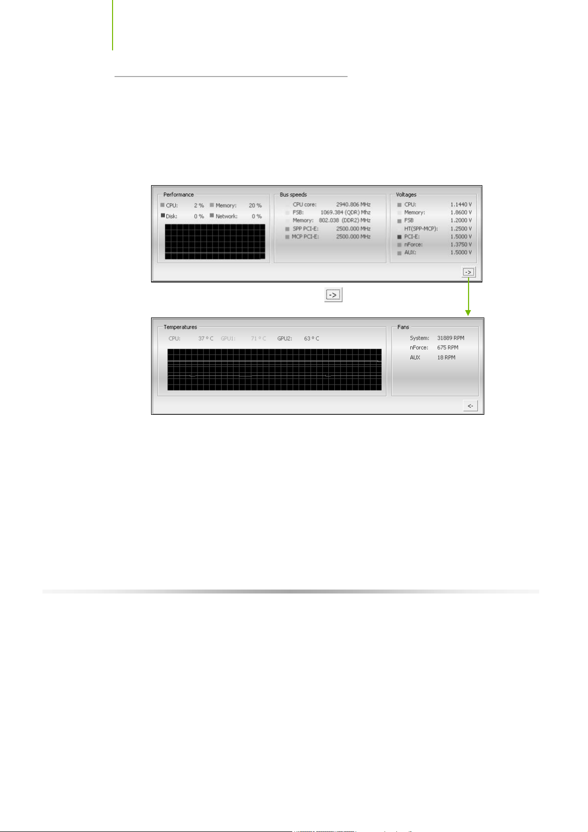
Installing and C onfiguring the TF680i SLI D eluxe Motherboard
NVIDIA Monitor
The NVIDIA Moni tor appli catio n can be used at any time wi th an y appli c ations
to view the real-time status of various system components. To display the
NVIDIA Monitor, select
Monitor
. This display shows the performance (usage) of the CPU, disk, memory,
and ne tw ork. It al so moni tors the Bu s sp eeds and voltages.
Star t ¾All Programs¾NVIDIA Corporat ion¾NVIDIA
To view temperatures and fans, click the
button.
70
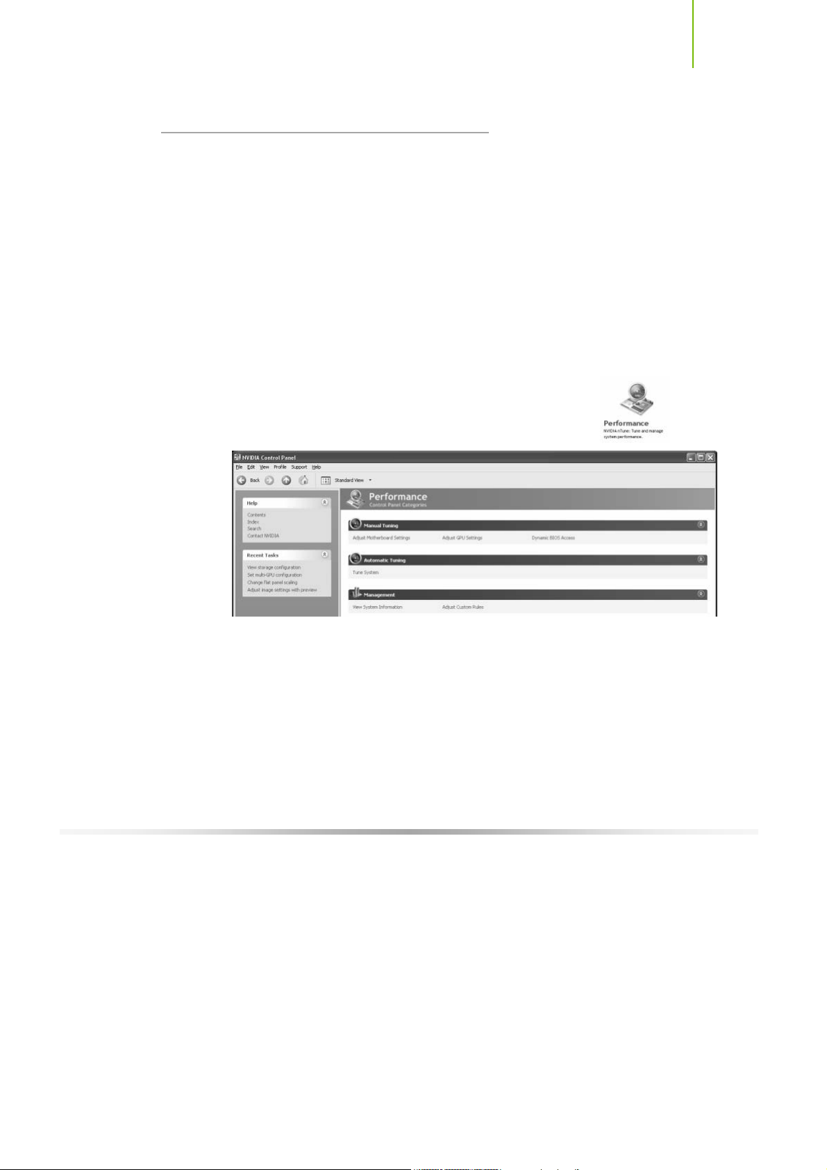
U sing NV IDIA S oftware
NVIDIA nTune 5.0
The Performance category is used to configure and manage NVIDIA nTune.
The NVIDIA nTune program is a full-featured application for accessing,
monitoring, and adjusting your system components (including bus speeds and
voltages) with clear, user-friendly control panels.
Overclock your system for the highest performance, or underclock it for a
nearly silent operation. All changes are performed within the Microsoft
Windows interface, enabling full functionality without the need to make
changes in the BIOS and reboot your system.
Use the following procedure to access nTune:
1. From the desktop, select
Corporation
2. Select
Categories
¾NVIDIA Control Panel.
Performance to display Performance Control P anel
.
Start¾A ll Progr ams ¾NVIDIA
Figure 18. Performance Control Panel Categories (nTune)
The Performance me nu pro vi des th e fol lowi ng opti on s:
¾ Manual Tuning
ª Adjust motherboard settings
ª Adjust GPU settings
ª Dynamic BIOS access
¾ Automatic Tuning
ª Tune system
71

Installing and C onfiguring the TF680i SLI D eluxe Motherboard
¾ Management
ª View system information
ª Adjust custom rules
Manual Tuning
The Manual Tuning option provides the ability to adjust motherboard settings,
adju st CPU setti ngs, and make changes to the BIOS.
Adjust Motherboard Sett ings
The controls in the Adjust Motherboar d Settings sc reen let you adjust th e
performance of the system clocks, system voltages, memory controller timings,
and system fans. By manually adjusting these speeds you are able to either
increase performance for gaming, or reduce performance to conserve power
and create a quieter environment.
72
Figure 19 shows the Adjust Motherboard Settings screen. Note that as you pass
the cursor over the various adjustments, notes display at the bottom of the
screen to explain each setting.
The number to the ri gh t of the sli der is the ne w bus speed that wi ll be ap plied .
Make adjustments by using the mouse to drag the slider. All changes take effect
immediately after selecting
Apply; however, these setting only remain active for
the current Windows session. This allows you to safely return to Windows if a
crash occurs, with no possibility of boot issues since the changes are not made
directly to the BIOS settings.
Note : All changes on Adjust Motherboard Setting s are dy namically m ade when you
apply them, and only remain activ e for the current Windows session. You can
s av e th e s e s et t i ngs as a pr of i l e f or u s e la t e r by us in g t h e Profile m e nu it em. If
a setting does not allow a change, it probably requires a reboot and s hould
be changed in the BI OS or from the Dynami c BIOS Access page (if av ailable).

U sing NV IDIA S oftware
Figure 19. Adjust Motherboard Settings (nTune)
CAUTION: Increasing the voltage or the clock speed of a component may
void its warranty due to exceeding recommended specifications. NVIDIA
a n d the boar d m anu fa c tur er ar e not re spo nsi ble f or da ma ge th at may o cc ur
when component tolerances are exceeded.
System Clocks
This section of the Adjust Motherboard Settings allows you to adjust the
reference clocks for the FSB, the SPP PCI Express, and the MCP PCI Express.
Note that as yo u ch an ge the
slider for the FSB reference
clock, the CPU core frequency,
the FSB Frequency and the
memory bus frequency are
dynamically changed.
73

Installing and C onfiguring the TF680i SLI D eluxe Motherboard
System Voltages
CAUTION: Overvoltaging any component can result in damage.
In this section of the Adjust Motherboard Settings you must understand what
you are changing. Overvoltaging any of the components can result in damage to
the components. From this menu, you can adjust the following voltages:
CPU
Memory
FSB
HyperTransport SSP MCP
nForce SPP
nForce MCP
Auxiliary
Always note the color of the indicator
square to the right of each slider. Green
indicates the voltage is within range and
will not damage any components.
Yellow means to proceed with caution;
you are no longer in the safe range. If the indicator square is red, you are
possible overvoltaging the component and could be causing damage.
74
System Fans
This section of the Adjust Motherboard
Settings menu allows you to control the CPU,
System, nForce, MCP, and the auxiliary fans.
You can either set all the fans to automatic
control or you can manually control each fan.
When in manual control, you can specify to
show the temperatures in Celsius or
Fahrenheit.

U sing NV IDIA S oftware
Memory Timing
This section of the Adjust Motherboard Settings allows you to adjust various
memory timings and cycles.
When yo u s elec t an opt i on, inf ormat i on expl aini ng
the selection is displayed in the area below the
Memory Timing box.
Clicking on View SPD … dis plays a
memory information window. This is
for information only and is not editable.
Row Address Strobe
Adjusts the minimum RAS active time. This is the amount of time between a
row being activated by Precharge and deactivated. A row cannot be
deactivated until tRAS has completed. The lower this value, the faster the
performance. However, if it is set too low it can cause data corruption by
deactivating the row to soon. Adjustable from 1 to 63.
Write Recovery Time
Memory timing that determines the delay between a write command and a
Precharge command is set to the same bank of memory. Adjustable from 1
to 15.
W to R Termination Turnaround
The Write-to-Read time is the number of clock cycles between the last write
data pair and the subsequent READ command to the same physical block.
Adjustable from 1 to 15.
RAS to CAS access
The RAS-to-CAS access (tRCD) is the amount of time in cycles for issuing
an acti ve comman d and the read/w rite comman ds. Adju stabl e from 1 to 15.
75

Installing and C onfiguring the TF680i SLI D eluxe Motherboard
RAS to RAS Delay
The RAS-to-RAS delay (tRRD) is the is the amount of cycles it takes to
activate the next bank of memory (this is the opposite of tRAS). The lower
the timing the better the system performance. However, this scenario can
cause instability. Adjustable from 1 to 15.
Refresh Rate
This value is filled in by the system and can not be changed by the user.
Memory bank switch
The row Precharge time (tRP) is the minimum time between active
commands and the read/writes of the next bank on the memory module.
Adjustable from 1 to 15.
R to W Turnaround
The Read-to-Write turnaround (tRWT) is a the amount of cycles for the
command to be executed when a Write command is received. Adjustable
from 1 to 15.
R to R Timing
the Read-to-Read time (tRDRD) is the number of clock cycles between the
last read and the subsequent READ command to the same physical bank.
Adjustable from 1 to 15.
Row Cycle Time
The Row Cycle Time is the minimum time in cycles it take a row to
complete a full cycle. This can be determined by tRC=tRAS+tRP. If this
value is set too short, it can cau se corruption of data. If this value is set too
high, it cau se s a loss in perform anc e bu t an increase in stabil ity. Adju stabl e
from 1 to 63 cycles
W to R Command Delay
The Write-to-Read (tWRD) command delay is the amount of cycles required
between a valid write command and the next read command. A lower cycle
time results in better performance but is can instability. Adjustable from 0 to
6 cycles.
W to W Timing
The Write-to-Write (tWRWR) timing is the number of clock cycles between
the last write and the subsequent Write command to the same physical bank.
Adjustable from 2 to 15 cycles.
CAS Latency
The CAS Latency (tCL) is the time (in number of clock cycles) that elapses
after the memory controller sends a request to read a memory location and
before the data is sent to the module's output pins. The value shown cannot
be changed.
76

U sing NV IDIA S oftware
Clock Drive S trength
This value is filled in by the system and can not be changed by the user.
Command Per Clock
The Command Per Clock (tCPC) sets the Command Rate for the memory
controller. The value shown cannot be changed
Async Latency
This value is filled in by the system and can not be changed by the user.
Adjust GPU Settings
Use this interface to adjust the graphics processing unit (GPU) on your video
card(s). You can override the shipped clock frequencies of your GPU and GPU
memory and set the GPU fan speed. Increasing the clock speeds increases your
GPU pe rform ance and may requ ire adjusti ng cooli ng to m aintain the same level
of reli abil ity.
When this option is
checked, al l
tem peratures are s hown
in Celsius. When this
opti on is not check ,
tem peratures are s hown
in Fahr en heit .
Figure 20. Adjust GPU Settings (nTune)
77

Installing and C onfiguring the TF680i SLI D eluxe Motherboard
Dynamic BIOS Access
Dynamic BIOS Access allows you to change some of your system BIOS
settings. The changes do not go into effect until you reboot your system. Since
these changes are made to actual BIOS settings in the CMOS, the settings
remain active until you change them again or restore the CMOS to the default
settings.
78
Figure 21. Dynamic BIOS Access (nTune)
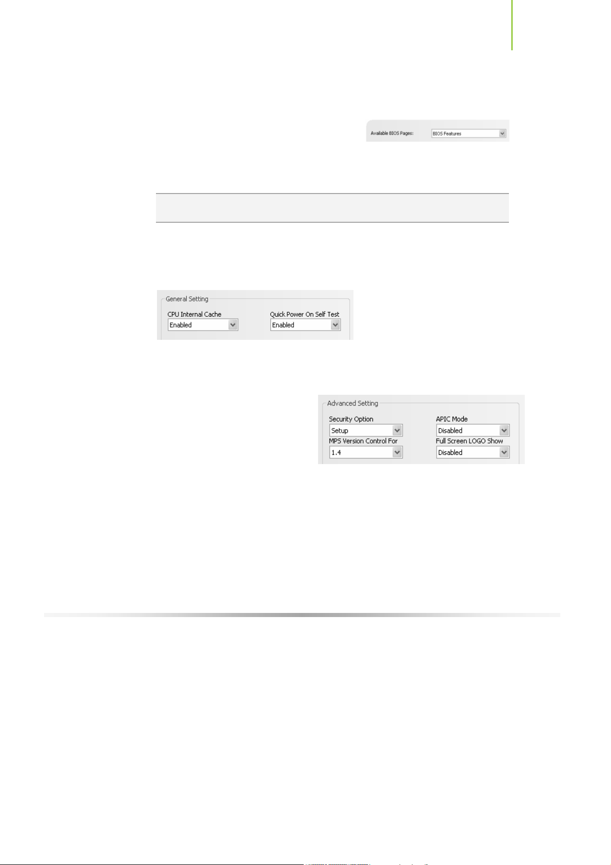
U sing NV IDIA S oftware
Available BIOS Pages
In the Dynamic BIOS Access page, select a BIOS page that you want to edit
from the Available BIOS Pages drop-down
menu The BIOS page you select determines
which items on the Dynamic BIOS Access menu are available for changing. To
edit an item, select an option from the drop-down menus associated with each
item. When finished making your changes, click
Note : This f eature is av ailable only with BIOS support f rom the motherboard
manufacturer.
OK or Apply.
General Settings
This section of the Dynamic BIOS Access menu allows you to Enable or
Disable the CPU Internal Cache and the Quick Power on Self Test (POST).
Advanced Settings
This section of the Dynamic BIOS Access menu allows you to set the following
options:
Security options
¾ Setup
¾ System
MPS Version Control For
¾ 1.1
¾ 1.4
APIC Mode
¾ Disable d
¾ Enabled
Full Screen LOGO Show
¾ Disable d
¾ Enabled
79

Installing and C onfiguring the TF680i SLI D eluxe Motherboard
Boot up Setting
This section of the Dynamic BIOS Access menu allows you to set the following
options:
First/Second/Third Boot Device
¾ Removable
¾ Hard Disk
¾ CDROM
¾ Legacy LAN
¾ Disable
Swap Floppy Drive
¾ Enable
¾ Disable
Boot Up Floppy Seek
¾ Enable
¾ Disable
Boot UP NumLock Status
¾ On
¾ Off
Gate A20 Option
¾ Normal
¾ Fast
80

U sing NV IDIA S oftware
Automatic Tuning
The NVIDIA nTune performance manager uses a complex searching algorithm
to determine the best possible and most stable performance for you system.
The nTune tuning engine pushes your system to the limits to test the highest
possible performance settings. Because of this, there may be instances of system
hangs during the testing. When you restart the system, nTune continues its
tuning process until the process is complete. It is highly recommended that you
chec k th e
bottom of the Tune System screen. The effects of the tuning process apply to
the current Windows session only.
The nTune tuning engine runs internal benchmark tests on your system and
creates performance profiles and rules.
CAUTION: Make sure to save a nd close all work prior to running the Tune
System function. Close all applications and do not perfor m other tasks
dur ing the tuning session.
Select to continue the tuning process upon reboot box at th e
Three tuning options are available on the Tune System menu:
Course tuning takes approximately 20 minutes to run w hile it adjusts
system bus speeds and parameters. It first saves current bus speeds as two
profiles: the
Bestsy st em.npe with the highest passing settings.
Fine tuning takes approximately three (3) hours and performs a more
Default .np e file with current bus speeds and
co mple x tuni ng on bu s spe eds, me mory ti mings, and vol tages. This mor e
complex testing achieves maximum performance.
Tuning using custom settings allows you to select specific areas to test
and the duration of the tests. Remember that a longer tuning session results
in more precise and stable settings. The progress of your test and the results
upon completion are displayed when the benchmarks are being executed.
You can cancel the tests at any time.
81

Installing and C onfiguring the TF680i SLI D eluxe Motherboard
82
Figure 22. Tune System Menu (nTune)
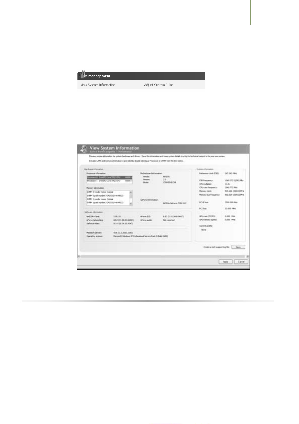
U sing NV IDIA S oftware
Management
The Management option on the View System Information screen allows you to
vie w har dware, softw are, an d system in form ation and adju st pro fi les.
View System Information
This screen is for information purposes only (you cannot make any changes to
the information). The View System Information screen provides hardware,
software, and system information that you can save to a log file to assist
customer support or for your own uses.
Figure 23. View System Information (nTune)
83

Installing and C onfiguring the TF680i SLI D eluxe Motherboard
Hardware and driver version information can be viewed and saved using this
interface. The status of the system, including current system clock speeds,
system temperatures, memory timings, and system voltages can be logged.
Versions of NVIDIA software and other system software are listed under
Software information.
Detailed CPU and memory information is displayed when you double-click on a
processor or DIMM listed under Hardware information.
Double-click a processor to display information
84
Double-click a DIMM
to display information

U sing NV IDIA S oftware
Adjust Custom Rules
The Adjust Custom Rules selection provides you with the ability to create a rule
to define when the system should use a particular profile (
files) that was created from a manual or automatic tuning session.
With custom rules, you can make your system run faster when you are playing
games or make it run quieter when you are surfing the Internet.
.nsu files or .npe
Figure 24. Adjust Custom Rules (nTune)
85

Installing and C onfiguring the TF680i SLI D eluxe Motherboard
System Stability
System Stability lets you view your system’s status and perform system stability
testing. To access the System Stability menu, select
Start¾A ll Progr am s¾NVIDIA Corporat ion¾NVIDIA Contro l
Panel
and select Sy s tem S tab ility .
Perform Stability Test
Use Perfor m Stability Test to quickly diagnose potential system performance
issues and to gather troubleshooting data.
Stability Test performs a series of stress test to identify probable causes of
performance issues, creates a list of the results, and provides recommendations
for improvements. You can test the entire system (check All system components)
or ch eck in dividu al com pon ents.
86
Figure 25. Perform Stability Test
 Loading...