

Page 1

NF4ST-A9
FCC Information and Copyright
This equipment has been tes ted and f ound to comply with the limits of a C lass
B digital device, pursuant to Part 15 of th e FCC Rules. These limits are designed
to provide reasonable protection against harmful interference in a residential
installation. This equipment generates, uses and can radiate radio f r equency
energy and, if not ins ta lled and used in accordan ce with the instructions, may
cause harmful interferenc e to radio c ommu nications. There is no gu arantee
that interference will not occur in a particular installation.
The vendor makes no r epr es entations or warranties with respect to the
contents here and specia lly disclaims any implied wa rranties of merchan tability
or fitness for any purpose. Further the vendor reserves the right to revise this
publication and to ma ke changes to the contents here without obligation to
notify any party beforehand.
Duplication of this publication, in part or in whole, is not allowe d without first
obtaining the ven dor ’s approval in writing.
The content of this user’s manual is subject to be ch a nged without notice and
we will not be responsible for any mistak es foun d in this u ser’s manua l. All the
brand and product names are trademarks of their respective companies.
i
Page 2

Table of Contents
Chapter 1: Introduction.....................................................1
1.1 Motherboard Features............................................................ 1
1.2 Package Checklist...................................................................6
1.3 Layout & Components........................................................... 7
Chapter 2: Hardware Installation.....................................8
2.1 Central Processing Unit (CPU).............................................8
2.2 Fan Headers........................................................................... 10
2.3 Memory Modules Installation............................................. 11
2.4 Connectors, & Slots...............................................................12
Chapter 3: Headers & Jumpers Setup........................... 13
3.1 How to setup Jumpers.........................................................13
3.2 Detail Settings........................................................................13
Chapter 4: Useful Help....................................................19
4.1 Award BIOS Beep Code....................................................... 19
4.2 Troubleshooting....................................................................19
Chapter 5: NVIDIA RAID Functions................................20
5.1 Operation System ................................................................. 20
5.2 Raid Arrays............................................................................ 20
5.3 How RAID Works ................................................................ 21
Chapter 6: WarpSpeeder™............................................. 25
6.1 Introduction...........................................................................25
6.2 System Requirement.............................................................25
6.3 Installation.............................................................................26
6.4 [WarpSpeeder™] includes 1 tray icon and 5 panels........ 27
ii
Page 3

NF4ST-A9
CHAPTER 1: INTRODUCTION
1.1 MOTHERBOARD FEATURES
A. Hardware
CPU
Supports Socket 939.
Supports AMD Athlon 64 FX processor.
Supports AMD Athlon 64 processor.
Supports AMD Sempron processor.
AMD 64 architecture enables sim ultaneous 32 and 64 bit
computing.
Supports HyperTransport Technology.
Supports AMD Cool’n’Quiet Technology.
Chipset
NVIDIA nForce4 (CK8-04):
- Supports NVIDIA Firewall.
- Supports Gigabit Ethernet.
- Supports 10 USB 2.0 ports.
- Supports NVIDIA nTune Utility.
- Supports 1 PCI-Express x16 interface graphics slot.
- Supports 4 SATA ports, each channel up to 1.5Gb/s.
- Supports NVIDIA RAID functions, including RAID 0, RAID 1
and RAID 0+1.
- Supports 4 IDE disk drives with PIO Mode 5, Bride Mode
and Ultra DMA 33/66/100/133 Bus Master Mode.
- Compliant with AC’97 version2.3 specification.
- Complaints with PCI-Express Version 1.a specification.
Operating Systems
Supports Windows 2000 and Windows XP.
Note: Do not support Windows 98SE and Windows ME.
Supports SCO UNIX.
1
Page 4
NF4ST-A9
Dimensions
ATX Form Factor: 23.4cm (W) x 29.35cm (L)
Main Memory
Supports Dual Channel DDR.
Supports 8 banks in total.
Supports DDR333 and DDR400.
Certified DDR400 List:
- Please check the website:
http://www.biostar.com.tw/products/mainboard/board.php3?
name=NF4ST-A9
Maximum memory size i s 4GB.
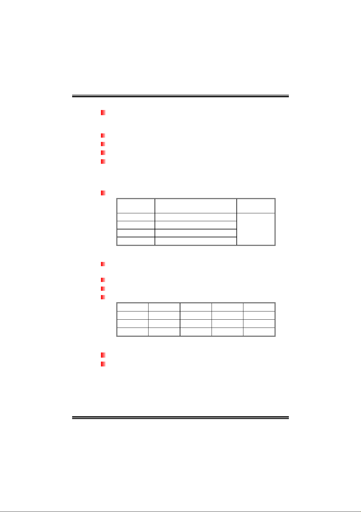
DIMM Socket
Location
DIMM1 128MB/256MB/512MB/1GB *1
DIMM2 128MB/256MB/512MB/1GB *1
DIMM3 128MB/256MB/512MB/1GB *1
DIMM4 128MB/256MB/512MB/1GB *1
DDR Module
Total Memory
Size (MB)
Max is 4 GB.
DDR Installation Notice:
Please follow the table below to install DDR memory module, or
the system may not boot up or may not function properly.
“SS” represents Single Side DDR memory module.
“DS” represents Double Side DDR memory module.
Star sign “*” represents leave the DIMM socket empty.
DIMM1 SS/DS
DIMM2
DIMM3
DIMM4
* * *
*
* * *
*
SS/DS SS/DS SS/DS
SS/DS SS/DS
SS/DS
SS/DS
On-board IDE
2 on-board connectors support 4 IDE disk drives.
Supports PIO mode 4, Block Mode and Ultra DMA
33/66/100/133 bus master mode.
2
Page 5

NF4ST-A9
Serial ATA
4 on-board Serial ATA connectors support 4 serial ATA (SATA)
ports.
Compliant with SATA 1.0 specification.
Data transfer rates up to 1.5Gb/s.
Slots
Three 32bit PCI bus master slots.
Two PCI-Express x1 slots:
- PCI Express 1.0a compliant.
- Bandwidth 250MB/s per direction.
One PCI-Express x16 slot.
- PCI Express 1.0a compliant.
- Maximum theoretical realized bandwidth of 4GB/s
simultaneously per direction, for an aggregate of 8GB/s
totally.
One Xtreme Graphics Port slot. (See p.12 for detail information)
Super I/O
Chip: ITE IT8712F.
Low Pin Count Interface.
Provides the most commonly used legacy Super I/O
functionality.
Environment Control initiatives,
- H/W Monitor
- Fan Speed Controller
- ITE's "Smart Guardian" function
On-board AC’97 Audio Sound Codec
Chip: ALC850.
Compliant with AC’97 version2.3 specificat ion.
Supports 8 channels audio output.
Chip: ALC655 (optional).
Compliant with AC’97 version2.3 specificat ion.
Supports 6 channels audio output.
3
Page 6

NF4ST-A9
IEEE 1394A Chip (optional)
Chip: VIA VT6307.
Supports 2 ports with transfer up to 400Mb/s.
Gigabit LAN
NVIDIA Gigabit MAC + VITESSE Gigabit PHY VSC8201.
Supports 10 Mb/s, 100 Mb/s and 1Gb/s auto-negotiation.
Half/Full duplex capability.
Supports personal Firewall setup.
Supports ACPI power management.
Supports NVIDIA StreamThru technology
- Isochronous controller paired with Hyper Transport results
in fastest networking performance
Security
NVIDIA Firewall technology
- Native firewall solution
Advanced features
- Remote access, configuration, monitoring
- Command line interface (CLI)
- WMI scripts.
Storage
NVIDIA RAID Technology
- RAID 0 disk striping for highest system and application
performance
- RAID 1 disk mirroring support for fault tolerance
Support for both SATA and ATA-133 disk controller
standards
- RAID 0+1 disk striping and mirroring for highest
performance with fault tolerance
Internal On-board Connectors and Headers
1 audio-out header supports audio-out facilities.
1 front panel header supports front panel facilities.
1 CD-in connector supports CD-ROM audio-in function.
1 SPDIF-out connector supports digital audio-out function.
4
Page 7
NF4ST-A9
1 SPDIF-in connector supports digital audio-in function
(optional).
1 IEEE1394 header supports 1 1394 Firewire port (optional).
1 floppy connector supports 2 FDD devices with 360K, 720K,
1.2M, 1.44M and 2.88Mbytes.
2 IDE connectors support 4 IDE disk drives.
3 USB headers support 6 USB 2.0 ports at front panel.
4 Serial ATA connectors support 4 SATA devices.
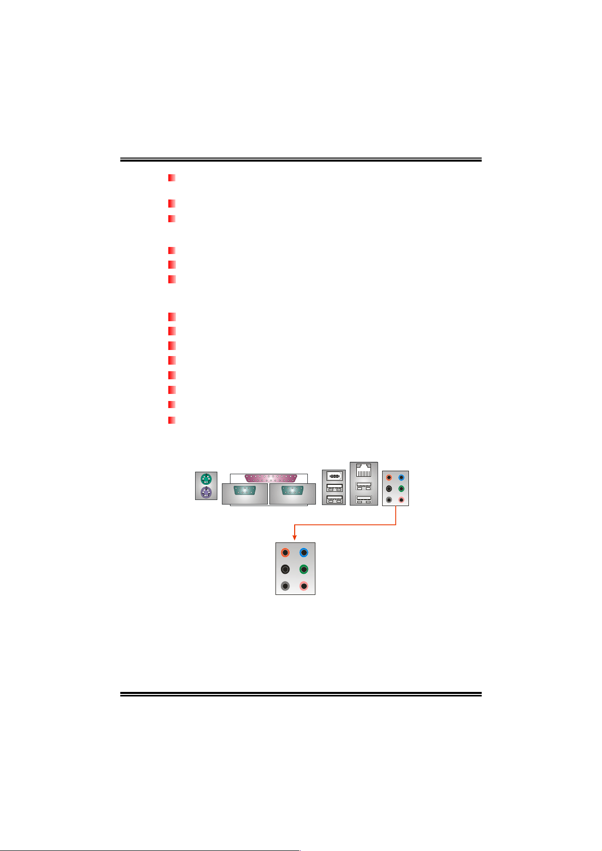
Rear (Back Panel) Side Connectors
1 PS/2 Mouse Port.
1 PS/2 Keyboard Port.
1 Printer Port.
1 Serial Port. (JCOM2 is optional.)
1 1394 Firewire Port (optional).
1 RJ-45 LAN jack.
4 USB 2.0 Ports.
6 audio ports support 8 channels audio-out facilities.
(With ALC850)
JKMBS1
PS/2
Mouse
JPRNT1
Printer Port
J1394_USB 1
1394 Port
(optional)
JUSBLAN1
LAN
Connector
PS/2
Keyboard
COM1
JCOM1
Center/Left
Rear
Side
COM2
(optional)
JCOM2
(optional)
USB *2
USB *2
Line-in
Line-out
MIC-in
5
Page 8
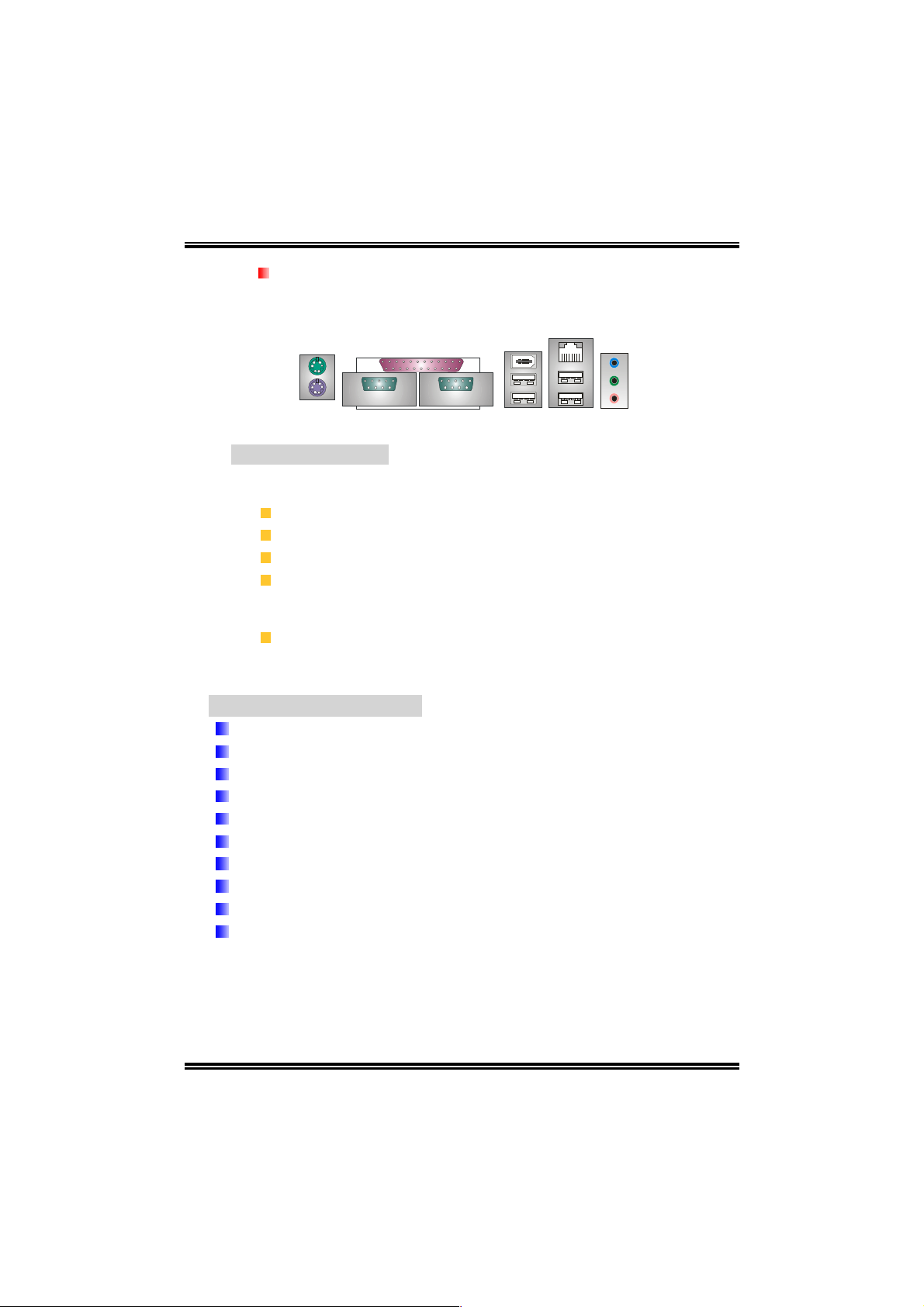
3 audio ports support 6 channels audio-out facilities.
(With ALC655, optional)
JKMBS1
PS/2
Mouse
PS/2
Keyboard
B. BIOS & Software
BIOS
Award legal BIOS.
Supports APM1.2.
Supports ACPI.
Supports USB Function.
Bundled Software
Supports 9th Touch™, WINFLASHER™ and FLASHER™.
COM1
JCOM1
NF4ST-A9
JPRNT1
Printer Port
COM2
(optional)
JCOM2
(optional)
J1394_USB 1
1394 Port
(optional)
USB *2
JUSBLAN1
LAN
Connector
USB *2
Line-in/Rear
Line-out
MIC-in/
Center/
Left
1.2 PACKAGE CHECKLIST
FDD Cable X 1
HDD Cable X 1
User’s Manual X 1
Fully Setup Driver CD X 1
Rear I/O Panel for ATX Case X 1
USB 2.0 Cable X1 (optional)
S/PDIF Cable X 1 (optional)
Serial ATA Cable X 1 (optional)
IEEE 1394 Cable X 1 (optional)
Serial ATA Power Switch Cable X 1 (optional)
6
Page 9
NF4ST-A9
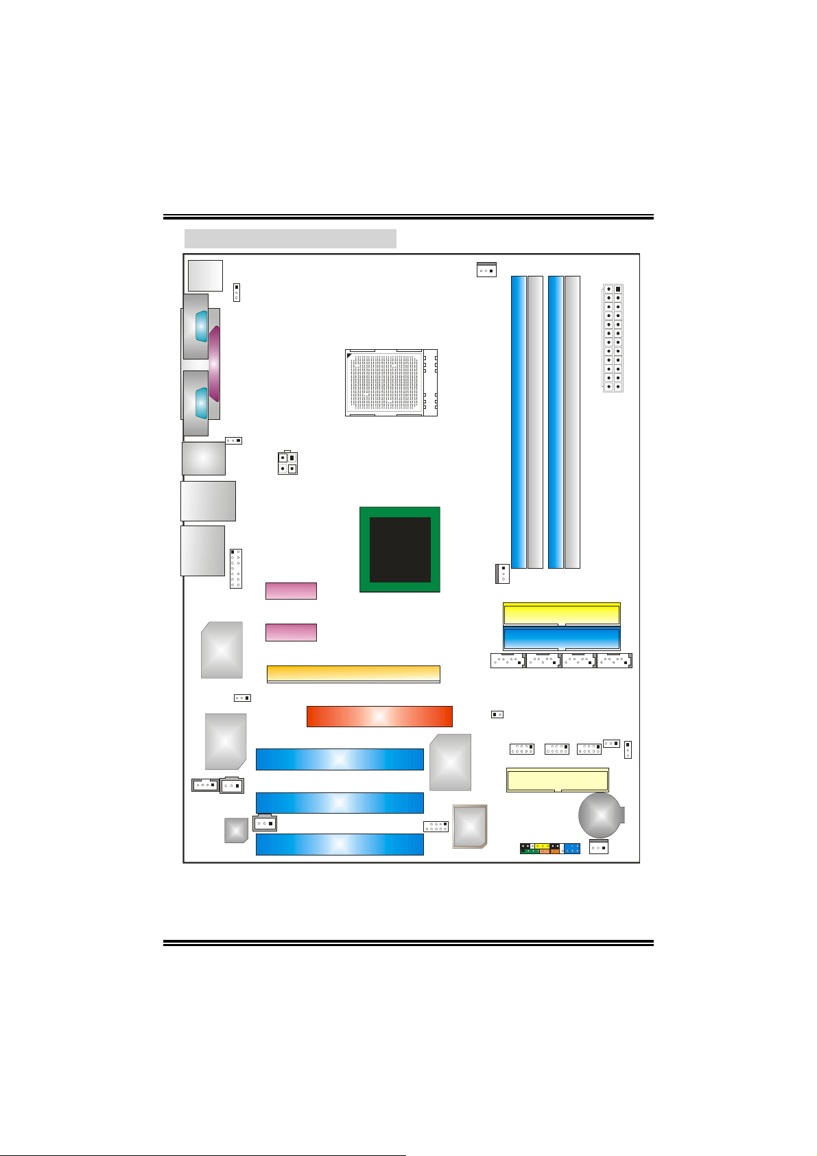
1.3 LAYOUT & COMPONENTS
JKBMS1
JCOM1
JCOM2
(optional)
J1394_USB1
JUSBLAN1
JKBMSV1
C
O
M
1
JPRNT1
C
O
M
2
J1394_USBV1
JATXPWR2
CPU1
JCFAN1
JATXPWR1
Socket 939
DIMM1
DIMM2
DIMM4
DIMM3
EARPHONEJACK1
JAUDIO2
PCI-EX x1
PEX1-2
PCI-EX x1
PEX1-1
Giga LAN
J1394PWR1
(optional)
IEEE 1394
Chip
(optional)
JCDIN1
PCI1
JSPDIF_OUT
PCI2
Codec
JSPDIF_IN1
PCI3
Note: ■ represents the 1
XGP1
PCI-EX16
st
nForce4
(CK8-04)
pin.
Super I /O
J1394A1
(optional)
JNBFAN1
JSATA1 JSATA2 JSATA3 JSATA4
JCI1
BIOS
JPANEL1
IDE2
IDE1
FDD1
JUSB3JUSB2JUSB1
JUSBV1
JCMOS1
BA T1
JSFAN1
7
Page 10
NF4ST-A9
CHAPTER 2: HARDWARE INSTALLATION
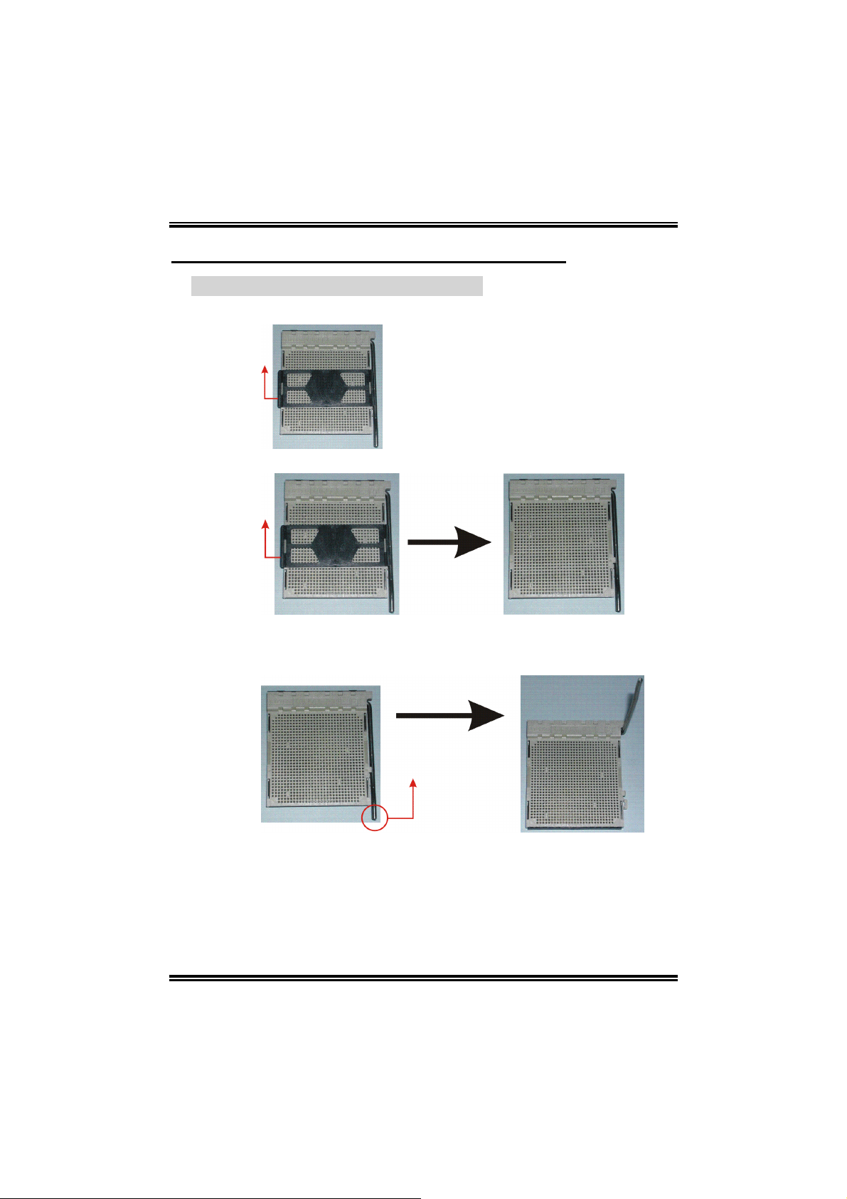
2.1 CENTRAL PROCESSING UNIT (CPU)
Step 1: Remove the socket protection cap.
Step 2: Pull the lever sideways away from the socket and then raise the
lever up to a 90-degree angle.
8
Page 11
NF4ST-A9
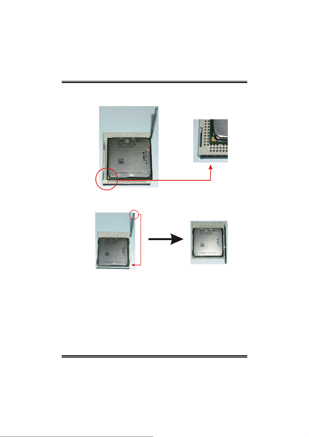
Step 3: Look for the black cut edge on socket, and the white dot on CPU
should point forwards this black cut edge. The CPU will fit only in
the correct orientation.
Step 4: Hold the CPU down firmly, and then close the lever to complete
the installation.
Step 5: Put the CPU Fan on the CPU and buckle it. Connect the CPU FAN
power cable to the JCFAN1. This completes the installation.
9
Page 12
NF4ST-A9
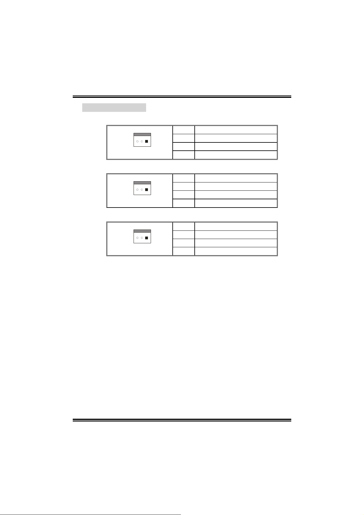
2.2 FAN HEADERS
CPU FAN Power Header: JCFAN1
Pin Assignment
1 Ground
1
3
System Fan Power Header: JSFAN1
1
3
North Bridge Fan Power Header: JNBFAN1
1
3
Note:
The JCFAN1, JSFAN1and JNBFAN1 support system cooling fan with
Smart Fan Control utility. It supports 3 pin head connector. When
connecting with wires onto connectors, please note that the red wi re is the
positive and should be connected to pin#2, and the black wire is Ground
and should be connected to GND.
2 CPU Fan Control
3 FAN RPM rate sense
Pin Assignment
1 Ground
2 +12V
3 FAN RPM rate sense
Pin Assignment
1 Ground
2 +12V
3 FAN RPM rate sense
10
Page 13
NF4ST-A9
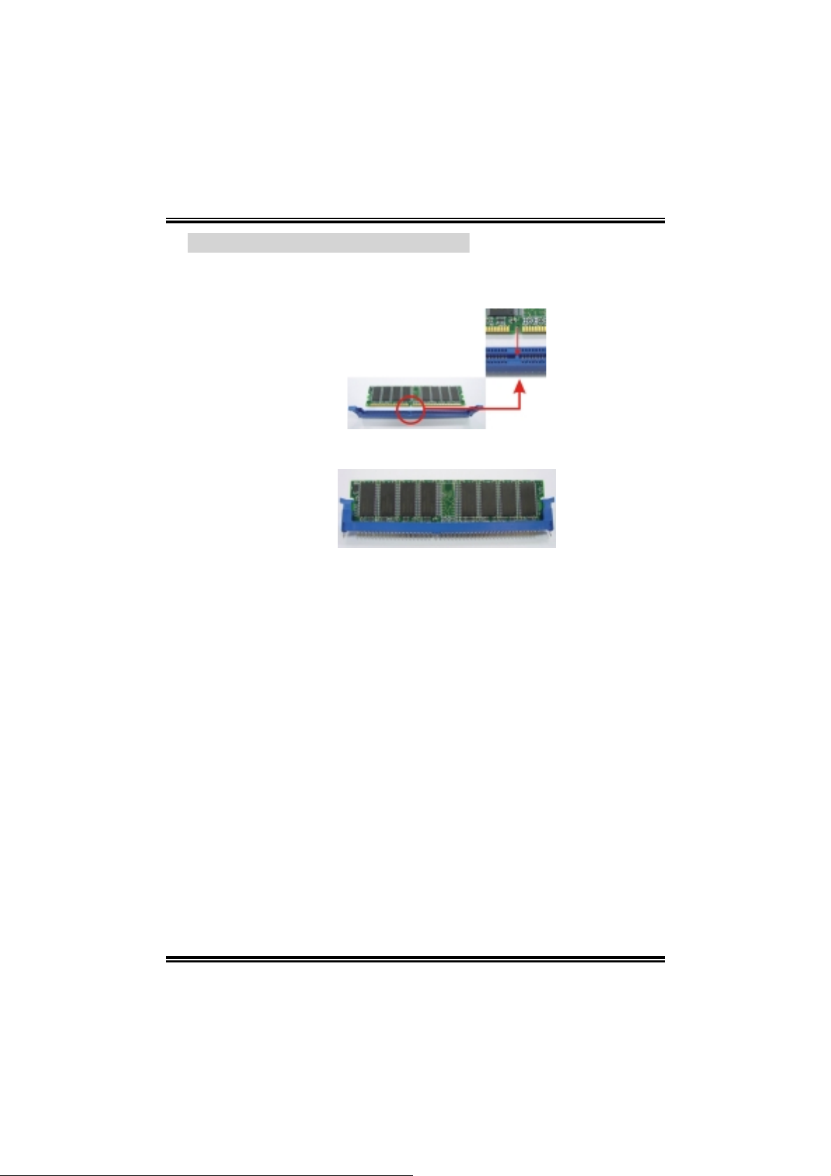
2.3 MEMORY MODULES INSTALLATION
1. Unlock a DIMM slot by pressing the retaining clips outward. Align a
DIMM on the slot such that the notch on the DIMM matches the break
on the Slot.
2. Insert the DIMM vertically and firmly into the slot until the retaining chip
snap back in place and the DIMM is properly seated.
11
Page 14

NF4ST-A9
2.4 CONNECTORS, & SLOTS
Floppy Disk Connector: FDD1
The motherboard provides a standard floppy disk connector that
supports 360K, 720K, 1.2M, 1.44M and 2.88M floppy disk types. This
connector supports the provided floppy drive ribbon cables.
Hard Disk Connectors: IDE1/IDE2
The motherboard has a 32-bit Enhanced PCI IDE Controller that
provides PIO Mode 0~5, Bus Master, and Ultra DMA 33/66/100/133
functionality. It has two HDD connectors IDE1 (primary) and IDE2
(secondary).
The IDE connectors can connect a master and a slave drive, so you can
connect up to four hard disk drives. The first hard drive should always be
connected to IDE1.
Peripheral Component Interconnect Slots: PCI1~PCI3
This motherboard is equipped with 3 standard PCI slot. PCI stands for
Peripheral Component Interconnect, and it is a bus standard for
expansion cards. This PCI slot is designated as 32 bits.
Xtreme Graphics Port Slot: XGP1
This XGP (Xtreme Graphics Port) slot is a special design that only
supports compatible AGP VG A card s.
To install the system with an add-on AGP VGA card, please make sure
to install the driver of add-on AGP VGA card before onboard VGA driver
installation. If the onboard VGA driver has already been installed before
you install the add-on AGP VGA card, the system will automatically set
the onboard VGA as the primar y graphics adapter .
For the onboard VGA driver can’t be removed completely, and to solve
this problem, please follow the steps below,
1. Disable onboard VGA utility under the operating system, and reboot
PC. After PC restarts, the system will automatically set the AGP
VGA card as the graphics adapter.
2. Re-install your operating system to ensure the AGP VGA card
function can be used.
Note:
Please go to “http://www.biostar.com.tw
about XGP compatible AGP cards.
” for more detailed information
12
Page 15
NF4ST-A9
4
CHAPTER 3: HEADERS & JUMPERS SETUP
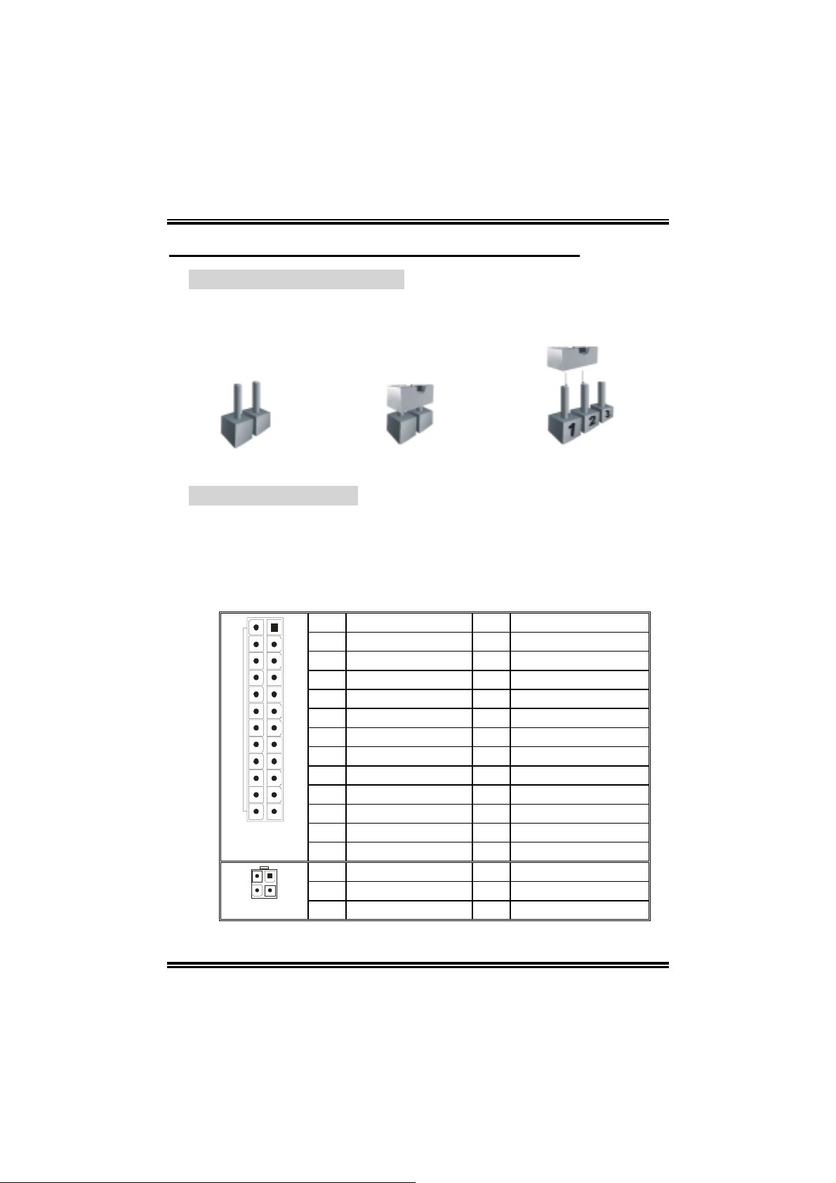
3.1 HOW TO SETUP JUMPERS
The illustration shows how to set up jumpers. When the jumper cap is
placed on pins, the jumper is “close”, if not, that means the jumper is
“open”.
Pin opened Pin closed Pin1-2 closed
3.2 DETAIL SETTINGS
ATX Power Source Connectors: JATXPWR1/JATXPWR2
JATXPWR1: This connector allows user to connect 20-pin power
connector on the ATX power supply.
JATXPWR2: By connecting this connector, it will provide +12V to CPU
power circuit.
13
2
JATXPWR1
JATXPWR2
1
Pin Assignment Pin Assignment
1 +3.3V 13 +3.3V
2 +3.3V 14 -12V
3 Ground 15 Ground
4 +5V 16 PS_ON
5 Ground 17 Ground
6 +5V 18 Ground
7 Ground 19 Ground
8 PW_OK 20 -5V
9 Standby Voltage +5V 21 +5V
10 +12V 22 +5V
12
1
2
34
11 +12V 23 +5V
12 Detect 24 Ground
Pin Assignment Pin Assignment
1 +12V 3 Ground
2 +12V 4 Ground
13
Page 16
NF4ST-A9
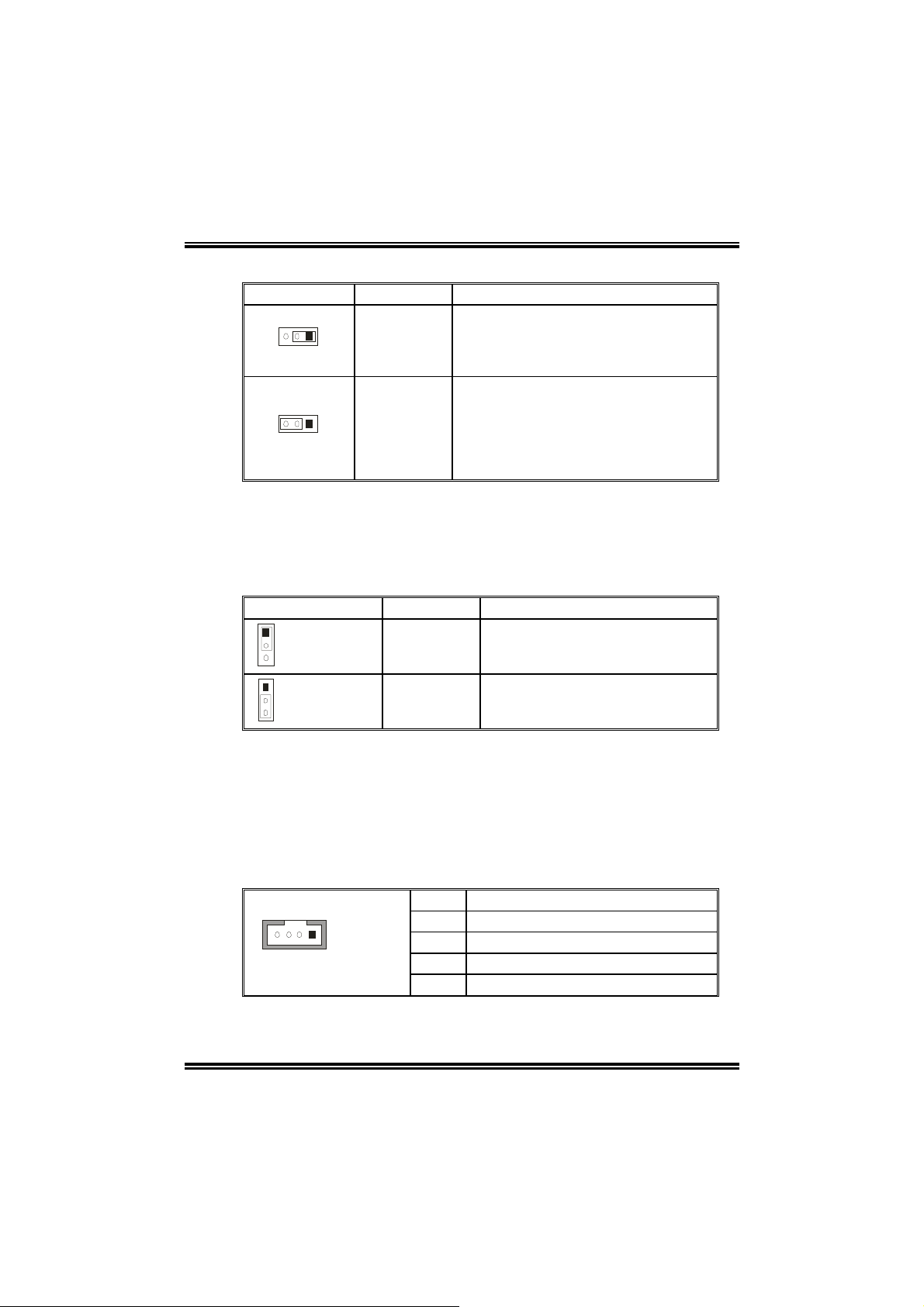
Power Source Headers for USB Ports: J1394_USBV1/JUSBV1
Assignment Description
3
1
Pin 1-2 close
Pin 2-3 close
3
1
+5V
+5V standby
Voltage
J1394_USBV1: +5V for USB ports at
J1394_USB1 and JUSBLAN1.
JUSBV1: +5V for front USB headers
(JUSB1/JUSB2/JUSB3).
J1394_USBV1: USB ports at
J1394_USB1 and JUSBLAN1 are
powered with +5V standby voltage.
JUSBV1: Front USB headers
(JUSB1/JUSB2/JUSB3) are powered
with +5V standby voltage.
Note:
In order to support this function “Power-on system via USB device,”
“J1394_USBV1/JUSBV1” jumper cap should be placed on Pin 2-3
individually.
Power Source Header for PS/2 Keyboard/Mouse: JKBMSV1
Assignment Description
1
3
Pin 1-2 close
1
3
Pin 2-3 close
Note:
In order to support this function “Power-on system via keyboard and
mouse”, “JKBMSV1” jumper cap should be placed on Pin 2-3.
+5V +5V for keyboard and mouse
+5V Standby
Voltage
PS/2 keyboard and mouse are
powered with +5V standby voltage.
CD-ROM Audio-in Connector: JCDIN1
This connector allows user to connect the audio source from the variety
devices, like CD-ROM, DVD-ROM, PCI sound card, PCI TV turner card
etc..
Pin Assignment
1 Left channel input
14
JCDIN1
2 Ground
3 Ground
4 Right channel input
14
Page 17
NF4ST-A9
r
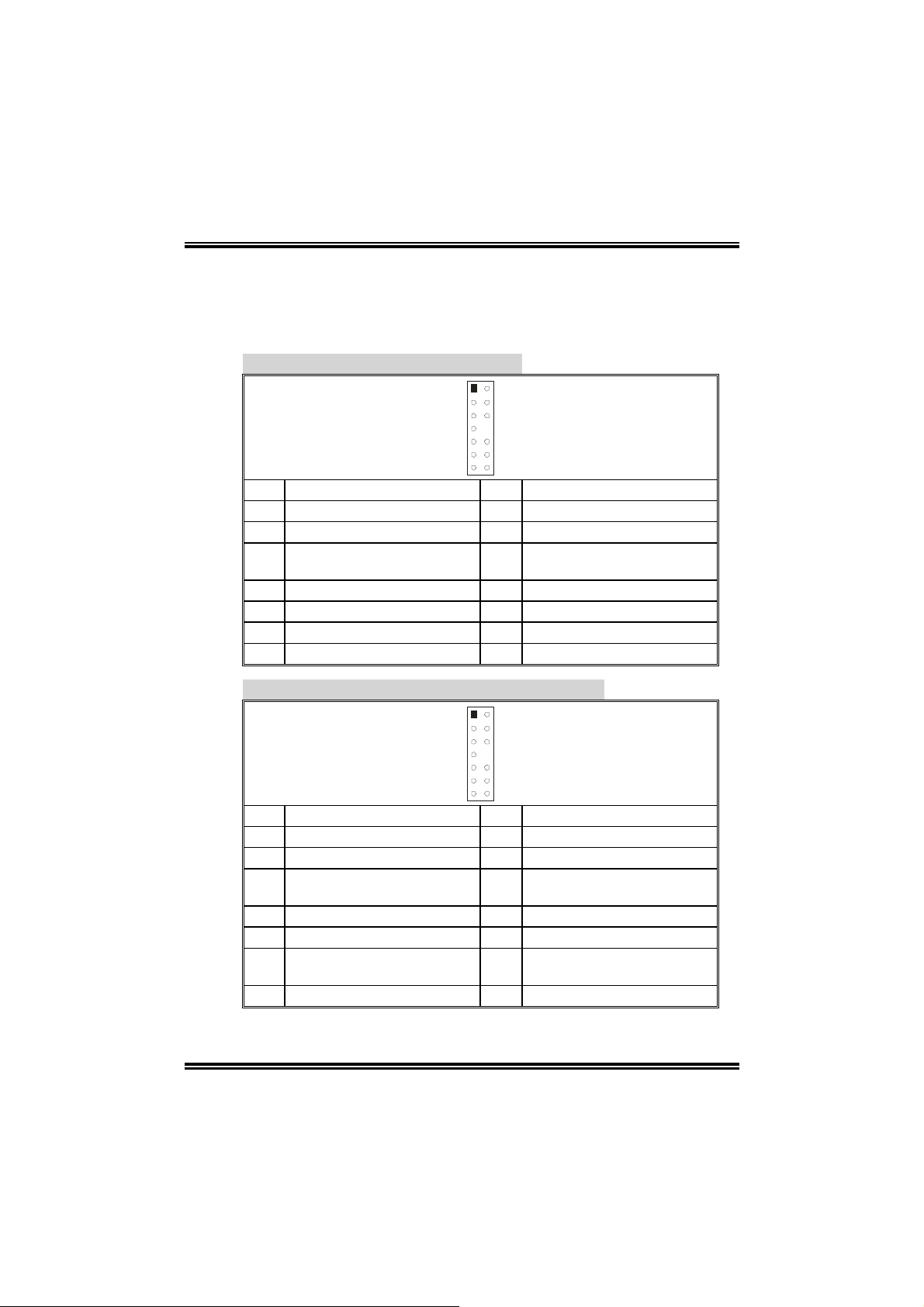
Front Panel Audio-out Header: JAUDIO2
This connector will allow user to connect with the front audio out put
headers on the PC case. It will disable the output on back panel audio
connectors.
With ALC850 Audio Sound Codec:
12
13 14
Pin Assignment Pin Assignment
1 Stereo MIC-in R. 2 Ground
3 Stereo MIC-in L. 4 Audio power
Right line out/Speaker out
5
Right
7 Reserved 8 Key
9 Left line out/Speaker out Left 10 Left line out/Speaker out Left
11 Right line in 12 Right line in
13 Left line in 14 Left line in
Right line out/Speaker out
6
Right
With ALC655 Audio Sound Codec (optional):
12
13 14
Pin Assignment Pin Assignment
1 Stereo MIC-in R/ Center 2 Ground
3 Stereo MIC-in L/ Bass 4 Audio power
Right line out/Speake
5
Right
7 Reserved 8 Key
9 Left line out/Speaker-out Left 10 Left line out/Speaker out Left
Right line in/Rear speaker
11
Right
13 Left line in/Rear speaker Left 14 Left line in/Rear speaker Left
-out
Right line out/Speaker-out
6
Right
Right line in/Rear speaker
12
Right
15
Page 18
NF4ST-A9
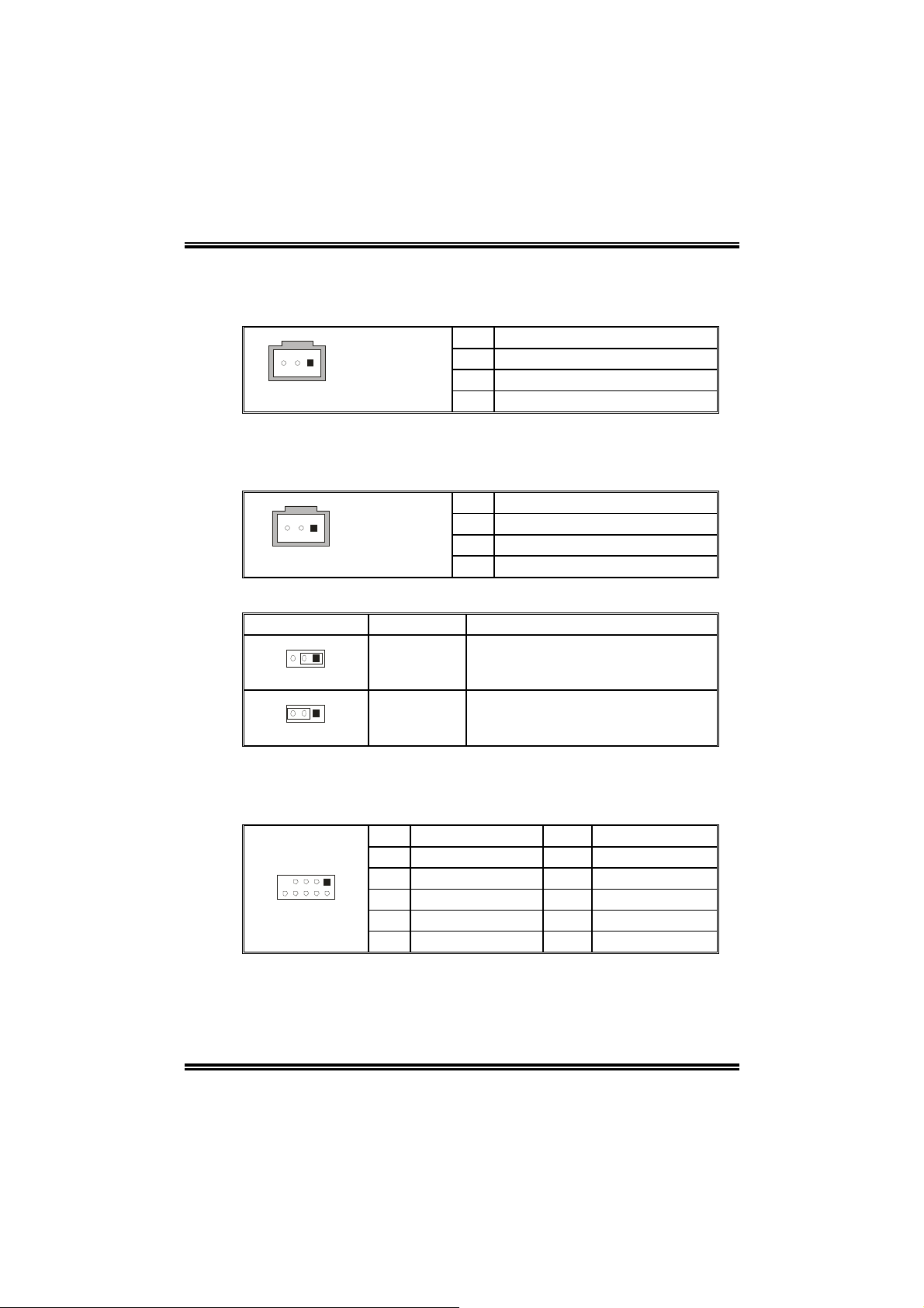
Digital Audio-out Connector: JSPDIF_OUT
This connector will allow user to connect the PCI bracket SPDIF output
header.
Pin Assignment
1 +5V
1
3
JSPDIF_OUT
2 SPDIF OUT
3 Ground
Digital Audio-in Connector: JSPDIF_IN1 (optional)
This connector will allow user to connect the PCI bracket SPDIF output
header.
Pin Assignment
1 +5V
1
3
JSPDIF_IN1
2 SPDIF In
3 Ground
Power Source Header for 1394 Chip: J1394PWR1 (optional)
Assignment Description
3
1
Pin 1-2 close
3
1
Pin 2-3 close
+3.3V
+3.3V SB +3.3V SB for 1394 chipset.
+3.3V for 1394 chipset.
(Default)
Header for 1394 Firewire Port at Front Panel: J1394A1 (optional)
This connector allows user to connect the front 1394 port for digital
image devices.
Pin Assignment Pin Assignment
1
10
2
1 A+ 2 A3 Ground 4 Ground
5 B+ 6 B7 +12v 8 +12V
9 Key 10 Ground
16
Page 19
NF4ST-A9
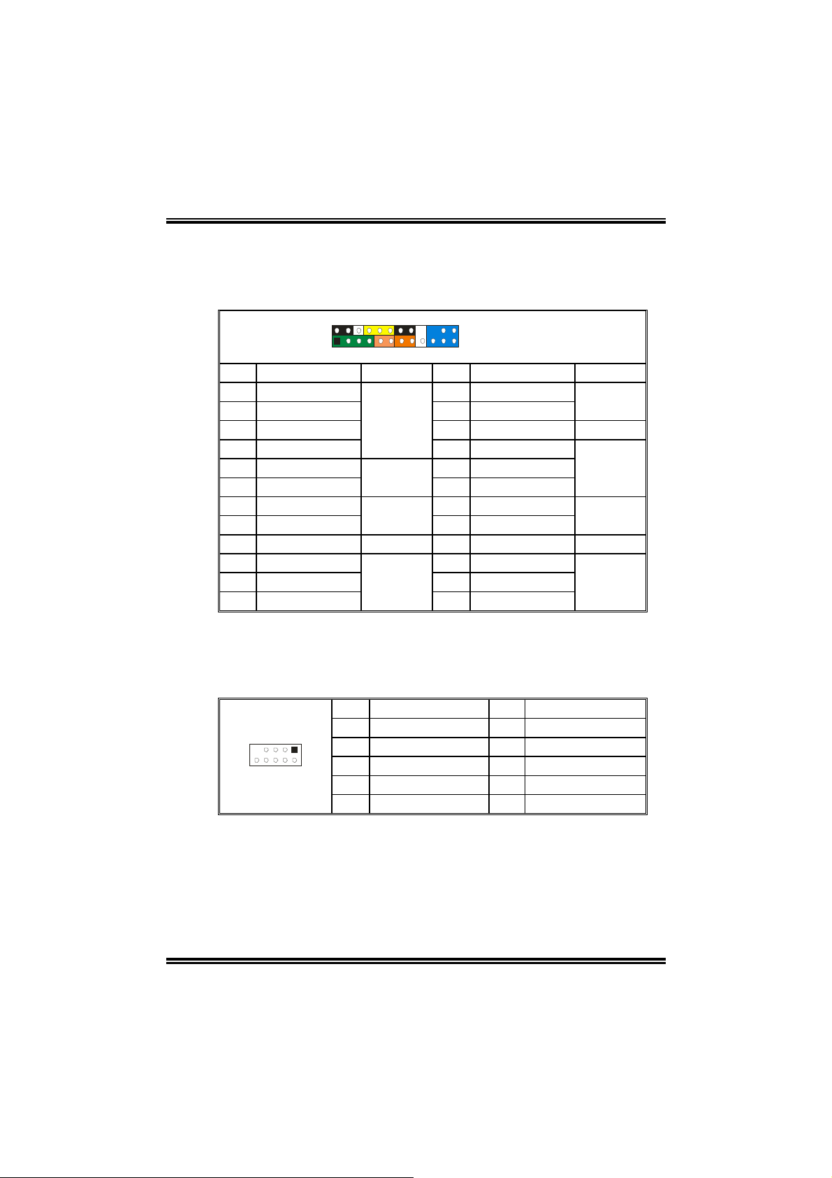
Header for Front Panel Faci li tie s: J PAN EL 1
This 24-pin connector includes Power-on, Reset, HDD LED, Power LED,
Sleep button, speaker and IrDA Connection. It allows user to connect
the PC case’s front panel switch functions.
2
24
1
Pin Assignment Function Pin Assignment Function
1 +5V 2 Sleep control
3 N/A 4 Ground
5 N/A 6 N/A N/A
7 Speaker
9 HDD LED (+) 10 Power LED (+)
11 HDD LED (-)
13 Ground 14 Power button
15 Reset control
17 N/A 18 Key
19 N/A 20 Key
21 +5V 22 Ground
23 IRTX
Speaker
Connector
Hard drive
LED
Reset
button
IrDA
Connector
23
JPANEL1
8 Power LED (+)
12 Power LED (-)
16 Ground
24 IRRX
Sleep
button
Power LED
Power-on
button
IrDA
Connector
Headers for USB Ports at Front Panel: JUSB1~JUSB3
This connector allows user to connect additional USB cables at PC front
panel, and also can be connected with internal USB devices, like USB
card reader.
Pin Assignment Pin Assignment
1
10
2
1 +5V (fused) 2 +5V (fused)
3 USB- 4 USB5 USB+ 6 USB+
7 Ground 8 Ground
9 Key 10 NC
17
Page 20
NF4ST-A9
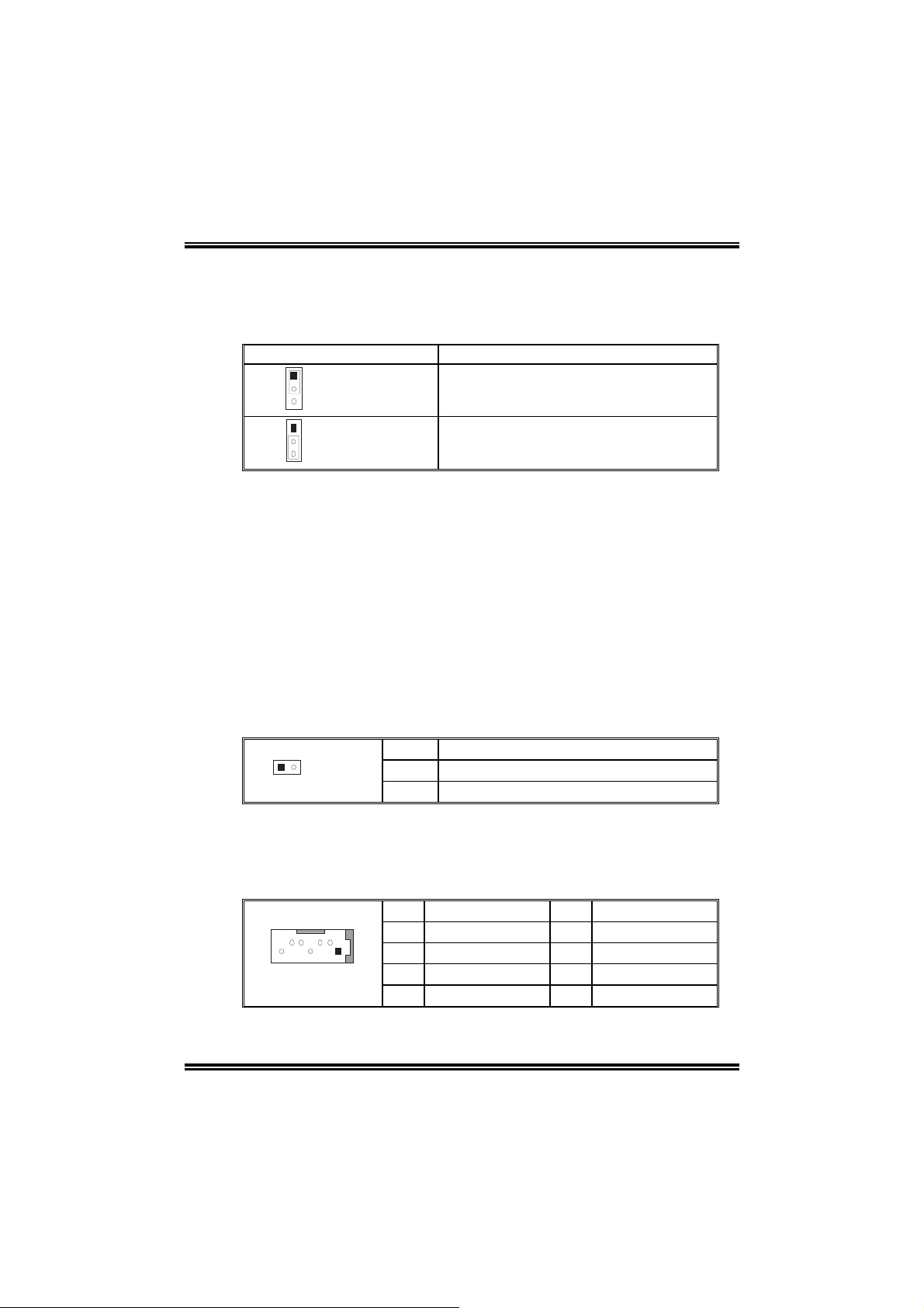
Close CMOS Header: JCMOS1
By placing the jumper on pin2-3, it allows user to restore the BIOS safe
setting and the CMOS data, please carefully follow the procedures to
avoid damaging the motherboard.
JCMOS1 Assignment
1
3
Pin 1-2 close
1
3
Pin 2-3 close
※
※ Clear CMOS Procedures:
※※
Normal Operation (Default).
Clear CMOS data.
1. Remove AC power line.
2. Set the jumper to “Pin 2-3 close”.
3. Wait for five seconds.
4. Set the jumper to “Pin 1-2 close”.
5. Power on the AC.
6. Reset your desired password or clear the CMOS data.
Case Open Header: JCI1
This connector allows system to monitor PC case open status. If the
signal has been triggered, it will record to the CMOS and show the
message on next boot-up.
Pin Assignment
2
1
JCI1
1 Case open signal
2 Ground
Serial ATA Connector: JSATA1~JSATA4
The motherboard has a SATA Controller in nForce4 (CK8-04) with 4
channels SATA interface, it satisfies the SATA 1.0 spec and with transfer
rate of 1.5Gb/s.
Pin Assignment Pin Assignment
1 Ground 2 TX+
7
1
4
3 TX- 4 Ground
5 RX- 6 RX+
7 Ground
18
Page 21

NF4ST-A9
CHAPTER 4: USEFUL HELP
4.1 AWARD BIOS BEEP CODE
Beep Sound Meaning
One long beep followed by two short
beeps
High-low siren sound CPU overheated
One Short beep when system boot-up No error found during POST
Long beeps every other second No DRAM detected or install
4.2 TROUBLESHOOTING
Probable Solution
1. No power to the system at all
Power light don’t illuminate, fan
inside power supply does not turn
on.
2. Indicator light on keyboard does
not turn on.
System inoperative. Keyboard lights
are on, power indicator lights are lit,
and hard drive is spinning.
System does not boot from hard disk
drive, can be booted from optical drive .
System only boots from optical drive.
Hard disk can be read and applications
can be used but bootin g fro m hard d is k
is impossible.
Screen message says “Invalid
Configuration” or “CMOS Failure.”
Cannot boot system after installing
second hard drive.
Video card not found or video card
memory bad
System will shut down automatically
1. Make sure power cable is
securely plugged in.
2. Replace cable.
3. Contact technical support.
Using even pressure on both ends of
the DIMM, press down firmly until the
module snaps into place.
1. Check cable running from disk to
disk controller board. Make sure
both ends are secur ely plug ge d i n;
check the drive type in the
standard CMOS setup.
2. Backing up the hard drive is
extremely important. All har d disk s
are capable of breaking down at
any time.
Back up data and applications files.
Reformat the hard drive. Re-install
applications and data using backup
disks.
Review system’s equipment. Make
sure correct information is in setup.
Set master/slave jumpers correctly.
Run SETUP program and select
correct drive types. Call the drive
manufacturers for compatibility with
other drives.
19
Page 22

NF4ST-A9
CHAPTER 5: NVIDIA RAID FUNCTIONS
5.1 OPERATION SYSTEM
Windows XP home Edition
Windows XP Professional Edition
Windows 2000 Professional
5.2 RAID ARRAYS
NVRAID supports the following types of RAID arrays:
RAID 0:
RAID 0 defines a disk striping scheme that improves disk read and writes
times for many applications.
RAID 1:
RAID 1 defines techniques for mirroring data.
RAID 0+1:
RAID 0+1 combines the techniques used in RAID 0 and RAID 1.
Spanning (JBOD):
JBOD provides a method for combining drives of different sizes in to one
large disk.
20
Page 23

NF4ST-A9
5.3 HOW RAID WORKS
RAID 0:
The controller “stripes” data across multiple drives in a RAID 0 array
system. It breaks up a large file into smaller blocks and performs disk
reads and writes across multiple drives in parallel. The size of each
block is determined by the strip size parameter, which you set during
the creation of the RAID set based on the system environment.
This technique reduces overall disk access time and offers high
bandwidth.
nVIDIA
nForce 4
(CK8-04)
Block 1
Block 3
Block 5
Block 2
Block 4
Block 6
Features and Benefits
Drives: Minimum 1, and maximum is up to 6 or 8. Depending on
the platform.
Uses: Intended for non-critical data requiring high data
throughput, or any environment that does not require fault
tolerance.
Benefits: provides increased data throughput, especially for
large files. No capacity loss penalty for parity.
Drawbacks: Does not deliver any fault tolerance. If any drive in
the array fails, all data is lost.
Fault Tolerance: No.
21
Page 24

NF4ST-A9
RAID 1:
Every read and write is actually carried out in parallel across 2 disk
drives in a RAID 1 array system. The mirrored (backup) copy of the
data can reside on the same disk or on a second redundant drive in the
array. RAID 1 provides a hot-standby copy of data if the active volume
or drive is corrupted or becomes unavailable because of a hardware
failure.
RAID techniques can be applied for high-availability solutions, or as a
form of automatic backup that eliminates tedious manual backups to
more expensive and less reliable media.
nVIDIA
nForce 4
(CK8-04)
Block 1
Block 2
Block 3
Block 1
Block 2
Block 3
Features and Benefits
Drives: Minimum 2, and maximum is 2.
Uses: RAID 1 is ideal for small databases or any other
application that requires fault tolerance and minimal capacity.
Benefits: Provides 100% data redundancy. Should one drive
fail, the controller switches to the other drive.
Drawbacks: Requires 2 drives for the storage space of one
drive. Performance is impaired during drive rebuilds.
Fault Tolerance: Yes.
22
Page 25

NF4ST-A9
RAID 0+1:
RAID 0 drives can be mirrored suing RAID 1 techniques. Resulting in a
RAID 0+1 solution for improved performance plus resiliency.
nVIDIA
nForce 4
(CK8-04)
Block 1
Block 3
Block 5
Block 2
Block 4
Block 6
Block 1
Block 3
Block 5
Block 2
Block 4
Block 6
Features and Benefits
Drives: Minimum 4, and maximum is 6 or 8, depending on the
platform.
Benefits: Optimizes for both fault tolerance and performance,
allowing for automatic redundancy. May be simultaneously used
with other RAID levels in an array, and allows for spare disks.
Drawbacks: Requires twice the available disk space for data
redundancy, the same as RAID level 1.
Fault Tolerance: Yes.
23
Page 26

NF4ST-A9
Spanning (JBOD):
JBOD stands for “Just a Bunch of Disks”. Each drive is accessed as if it
were on a standard SCSI host bus adapter. This is useful when a single
drive configuration is needed, but it offers no speed improvement or
fault tolerance.
nVIDIA
nForce 4
(CK8-04)
Single Logical
Drive
Disk 1: 40GB
Disk 2: 80GB
Disk 3: 40GB
Disk 4: 120GB
Features and Benefits
Uses: JBOD works best if you have odd sized drives and you
want to combine them to make one big drive.
Benefits: JBOD provides the ability to combine odd size drives
using all of the capacity of the drives.
Drawbacks: Decreases performance because of the difficulty in
using drives concurrentl y.
Fault Tolerance: Yes.
※
For more d etailed setup information, p leas e refer t o the Driver CD, or
http://www.nvidia.com/page/pg_20011106217193.html to download
go to
NVIDIA nForce Tutorial Flash.
24
Page 27

NF4ST-A9
CHAPTER 6: WARPSPEEDER™
6.1 INTRODUCTION
[WarpSpeeder™], a new powerful control utility, features three
user-friendly functions including Overclock Manager, Overvoltage
Manager, and Hardware Monitor.
With the Overclock Manager, users can easily adjust the frequency they
prefer or they can get the best CPU performance with just one click. The
Overvoltage Manager, on the other hand, helps to power up CPU core
voltage and Memory voltage. The cool Hardware Monitor smartly indicates
the temperatures, voltage and CPU fan speed as well as the chipset
information. Also, in the About panel, you can get detail descriptions about
BIOS model and chipsets. In addition, the frequency status of CPU,
memory, AGP and PCI along with the CPU speed are synchronically
shown on our main panel.
Moreover, to protect users' computer systems if the setting is not
appropriate when testing and results in system fail or hang,
[WarpSpeeder™] technology assures the system stability by automatically
rebooting the computer and then restart to a speed that is either the
original system speed or a suitable one.
6.2 SYSTEM REQUIREMENT
OS Support: Windows 98 SE, Windows Me, Windows 2000, Windows XP
DirectX: DirectX 8.1 or above. (The Windows XP operating system
includes DirectX 8.1. If you use Windows XP, you do not need to install
DirectX 8.1.)
25
Page 28

NF4ST-A9
6.3 INSTALLATION
1. Execute the setup execution file, and then the following dialog will pop
up. Please click “Next” button and follow the default procedure to
install.
2. When you see the following dialog in setup procedure, it means setup
is completed. If the “Launch the WarpSpeeder Tray Utility” checkbox
is checked, the Tray Icon utility and [WarpSpeeder™] utility will be
automatically and immediately launched after you click “Finish”
button.
Usage:
The following figures are just only for reference, the screen printed in
this user manual will change according to your motherboard on hand.
26
Page 29

NF4ST-A9
6.4 [WARPSPEEDER™] INCLUDES 1 TRAY ICON AND 5 PANELS
1. Tray Icon:
Whenever the Tray Icon utility is launched, it will display a little tray
icon on the right side of Windows Taskbar.
This utility is responsible for conveniently invoking [WarpSpeeder™]
Utility. You can use the mouse by clicking the left button in order to
invoke [WarpSpeeder™] directly from the little tray icon or you can
right-click the little tray icon to pop up a popup menu as following
figure. The “Launch Utility” item in the popup menu has the same
function as mouse left-click on tray icon and “Exit” item will close
Tray Icon utility if selected.
27
Page 30

NF4ST-A9
2. Main Panel
If you click the tray icon, [WarpSpeeder™] utility will be invoked.
Please refer to the following figure; the utility’s first window you will
see is Main Panel.
Main Panel contains features as follows:
a. Display the CPU Speed, CPU external clock, Memory clock,
AGP clock, and PCI clock information.
b. Contains About, Voltage, Overclock, and Hardware Monitor
Buttons for invoking respective panels.
c. With a user-friendly Status Animation, it can represent 3
overclock percentage stages:
Man walking→overclock percentage from 100% ~ 110 %
Panther running→overclock percentage from 110% ~ 120%
Car racing→overclock percentage from 120% ~ above
28
Page 31

NF4ST-A9
3. Voltage Panel
Click the Voltage button in Main Panel, the button will be highlighted
and the Voltage Panel will slide out to up as the following figure.
In this panel, you can decide to increase CPU core voltage and
Memory voltage or not. The default setting is “No”. If you want to get
the best performance of overclocking, we recommend you click the
option “Yes”.
29
Page 32

NF4ST-A9
4. Overclock Panel
Click the Overclock button in Main Panel, the button will be
highlighted and the Overclock Panel will slide out to left as the
following figure.
Overclock Panel contains the these feature s:
a. “–3MHz button”, “-1MHz button”, “+1MHz button”, and “+3MHz
button”: provide user the ability to do real-time overclock
adjustment.
Warning:
Manually overclock is potentially dangerous, especially when the
overclocking percentage is over 110 %. We strongly recommend you
verify every speed you overclock by click the Verify button. Or, you can
just click Auto overclock button and let [WarpSpeeder™] automatically
gets the best result for you.
b. “Recovery Dialog button”: Pop up the following dialog. Let user
select a restoring way if system need to do a fail-safe reboot.
30
Page 33

NF4ST-A9
c. “Auto-overclock button”: User can click this button and
[WarpSpeeder™] will set the best and stable performance and
frequency automatically. [WarpSpeeder™] utility will execute a
series of testing until system fail. Then system will do fail-safe
reboot by using Watchdog function. After reboot, the
[WarpSpeeder™] utility will restore to the hardware default
setting or load the verified best and stable frequency according
to the Recovery Dialog’s setting.
d. “Verify button”: User can click this button and [WarpSpeeder™]
will proceed a testing for current frequency. If the testing is ok,
then the current frequency will be saved into system registry. If
the testing fail, system will do a fail-safe rebooting. After reboot,
the [WarpSpeeder™] utility will restore to the hardware default
setting or load the verified best and stable frequency according
to the Recovery Dialog’s setting.
Note:
Because the testing programs, invoked in Auto-overclock and Verify,
include DirectDraw, Direct3D and DirectShow tests, the DirectX 8.1 or
newer runtime library is required. And please make sure your display
card’s color depth is High color (16 bit) or True color( 24/32 bit ) that is
required for Direct3D rendering.
5. Hardware Monitor Panel
Click the Hardware Monitor button in Main Panel, the button will be
highlighted and the Hardware Monitor panel will slide out to left as
the following figure.
In this panel, you can get the real-time status information of your
system. The information will be refreshed every 1 second.
31
Page 34

NF4ST-A9
6. About Panel
Click the “about” button in Main Panel, the button will be highlighted
and the About Panel will slide out to up as the following figure.
In this panel, you can get model name and detail information in hints
of all the chipset that are related to overclocking. You can also get
the mainboard’s BIOS model and the Version number of
[WarpSpeeder™] utility.
32
Page 35

NF4ST-A9
Note:
Because the overclock, overvoltage, and hardware monitor features
are controlled by several separate chipset, [WarpSpeeder™] divide
these features to separate panels. If one chipset is not on board, the
correlative button in Main panel will be disa bled, but wi ll not int er f er e
other panels’ functions. This property can make [WarpSpeeder™]
utility more robust.
33
Page 36

NF4ST-A9
2/17, 2005
34
Page 37

NF4ST-A9 BIOS Setup
BIOS Setup........................................................................................1
1 Main Menu....................................................................................................... 3
2 Standard CMOS Features...................................................................................6
3 Advanced BIOS Features ................................................................................... 9
4 Advanced Chipset Features............................................................................... 12
5 Integrated Peripherals ...................................................................................... 15
6 Power Management Setup................................................................................ 20
7 PnP/PCI Configurations ................................................................................... 23
8 PC Health Status ............................................................................................. 25
9 Frequency/Voltage Control...............................................................................27
i
Page 38

NF4ST-A9
BIOS Setup
Introduction
T his manual discussed Award™ Setup pr ogra m built into the ROM BIOS. The Setup
program allows users to modify the basic system configuration. This special informat ion is
th en stor ed in bat tery -b acke d RAM so tha t it retains the Set up info rmat ion wh en th e power
is turned off.
T he Award BIOS™ installe d in you r com pute r sy ste m’s ROM (Re ad Only Memory) is a
custom version of an industry standard BIOS. This means that it supports Nvidia CK8
processor input/output system. The BIOS provides critical low-level support for standard
devices such as disk drives and serial and parallel ports.
Addin g important has customized the Award BIOS™, but nonstandard, features such as
virus and password protection as well as special support for detailed fine-tuning of the
chipset controlling the entire system.
The rest of this manual is intended to guide you through the process of configuring your
system using Setup.
Plug and Play Support
These AWARD BIOS supports the Plug and P lay Version 1.0A specification. ESCD
(Extended System Configuration Data) write is supported.
EPA Green PC Support
This AWARD BIOS supports Version 1.03 of the EPA Green P C specification.
APM Support
These AWARD BIOS supports Vers ion 1.1&1.2 of the Advanced Power Management
(APM) specification. Power management features are implemented v ia the System
Management Interrupt (SMI). Sleep and Suspend power management modes are supported.
Power to the hard disk drives and video monitors can be managed by this AWARD BIOS.
ACPI Support
Award ACPI BIOS support Version 1.0 of Advanced Configurat ion and Power interface
specification (ACPI). It provides ASL code for power management and device
configuration capabilities as defined in the ACPI specification, developed by Microsoft,
Intel and Toshiba.
1
Page 39

NF4ST-A9
PCI Bus S upport
This AW ARD BIOS also supports Version 2.1 of the Intel PCI (Peripheral Component
Interconnect) local bus specification.
DRAM Support
DDR SDRAM (Double Data Rate Synchronous DRAM) are supported.
Suppo rted CP Us
T h is AWAR D BIO S s u ppor t s t h e AM D C P U.
Us i ng S etup
In general, you use the arrow keys to highlight items, press <Enter> to select, use the
<PgUp> and <PgDn> keys to change entries, press <F1> for help and press <Esc> to quit.
The following table provides more detail about how to navigate in the Setup program by
using the keyboard.
Keystroke Function
Up arrow Move to previous ite m
Down arrow Move to next i tem
Left arro w Move to the item o n the left (menu bar)
Right arrow Move to the item on the right (menu bar)
Move Enter Move to the item you desired
PgUp key Increase the numeric value or make c hanges
PgDn key Decrease the numeric value or make changes
+ Key Increase the numeric value or make changes
- Key Decrease the numeric value or make changes
Esc key Main Menu – Quit and not save changes into CMOS
F1 k ey Genera l help o n Setup navig ation ke ys
F5 key Load previous values from CMOS
F7 key Load the optimized defaults
F10 key Save all the CMOS changes and exit
Status Page Setup Menu and Option Page Setup Me nu – Exit
Current page and return to Main Menu
2
Page 40

NF4ST-A9
1 Main Menu
Once you enter Award BIOS™ CMOS Setup Utility, the Main Menu will appear on the
screen. The Main Menu allows you to select from several setup functions. Use the arrow
keys to select among the items and press <Enter> to accept and enter the sub-menu.
!! WARNING !!
The information about BIOS defaults on manual (Figu re
1,2,3,4,5,6,7,8,9) is just for reference, please refer to the BIOS
installed on board, for update information.
Fig ure 1. Main Menu
Standard CM OS Features
This submenu contains industry standard configurable options.
Advanced BIOS Features
This submenu allows you to configure enhanced features of the BIOS.
Advanced Chipset Features
This submenu allows you to configure special chipset features.
Integrated Pe ripherals
This submenu allows you to configure certain IDE hard drive options and Programmed
Input/ Output features.
3
Page 41

NF4ST-A9
Power Management Setup
This submenu allows you to configure the power management features.
PnP/PCI Configurations
This submenu allows you to configure certain “Plug and Play” and PCI options.
PC Health Status
This submenu allows you to monitor the hardware of your system.
Voltage Control
This submenu allows you to change CPU Vcore Vo lta ge and CP U/PCI clock. (Ho wever,
this function is strongly recommended not to use. Not properly change the voltage
and clock may cause the CPU or M/B damage!)
Lo a d O p timi ze d D e fa ul ts
This selection allows you to reload the BIOS when the system is having problems
particularly w ith the boot sequence. These configurations are factory settings optimized
for this system. A confirmation message will be disp layed before defaults are set.
Set Supervisor Password
Setting the supervisor password will prohibit everyone except the supervisor from making
changes using the CMOS Setup Utility. You will be prompted with to enter a password.
4
Page 42

NF4ST-A9
Set User Password
If the Supervisor P assword is not set, then the User Password will function in the same way
as the Supervisor Pa ss word. If the Su pervisor Pas sword is set and th e Use r P a ss word is
set, the “User” will only be able to view configurations but will not be able to change them.
Save & Exit Setup
Save all configuration changes to CMOS(memory) and exit setup. Confirmat ion message
will be displayed before proceeding.
Exit Without Saving
Abandon all changes made during the current session and exit setup. confirmation
message will be displayed before proceeding.
Upgrade BIOS
This submenu allows you to upgrade bios.
5
Page 43

NF4ST-A9
2 Standard CMOS Features
The items in Standard CMOS Setup Menu are divided into 10 categories. Each category
includes no, one or more than one setup items. Use the arrow keys to highlight the item and
then use the<PgUp> or <PgDn> keys to select the value you want in each item.
Figure 2. Standard CM OS Setup
6
Page 44

NF4ST-A9
Main Menu Selections
This table shows the selections that you can make on the Main Menu.
Item Options Description
Date mm : dd : yy Set the system date. Note
Time hh : mm : ss Set the system internal
IDE Primary Master Options are in its sub
menu.
IDE Primary Slave Options are in its su b
menu.
IDE Secondary Master Options are in its sub
menu.
IDE Secondary Slave Options are in its su b
menu.
Drive A
Drive B
Video EGA/VGA
360K, 5.25 in
1.2M, 5.25 in
720K, 3.5 in
1.44M, 3.5 in
2.88M, 3.5 in
None
CGA 40
CGA 80
MONO
that the ‘Day’ automatically
changes when you set the
date.
clock.
Press <Enter> to enter the
sub menu of detailed
options
Press <Enter> to enter the
sub menu of detailed
options.
Press <Enter> to enter the
sub menu of detailed
options.
Press <Enter> to enter the
sub menu of detailed
options.
Selec t th e ty pe of flop py
disk drive installed in your
system.
Select the default video
device.
7
Page 45

NF4ST-A9
Item Options Description
Halt On All Errors
No Errors
All, but Keyboard
All, but Diskette
All, but Disk/ Key
Base Memory N/A Displays the amount of
Extended Memory N/A Displays the amount of
Total Memory N/A Displays the total memory
Select the situation in which
you want the BIOS to sto p
the POST process and
notify you.
conventional memory
detected during boot up.
extended memory detected
during boot up.
available in the system.
8
Page 46

NF4ST-A9
3 Advanced BIOS Features
Figure 3. Advance d BIOS Setup
Cache Setup
These BIOS attempt to load the operating system from the device in the sequence selected in
these items.
CP U Interna l Cache
Depending on the CPU/chipset in use, you may be able to increase memory
access time with this option.
Enabled (default) Enable cache.
Disab led Disab le cache.
External Cache
This option enables or disables “Level 2” secondary cache on the CPU, which
may improve performance.
Enabled (default) Enable cache.
Disab led Disable cache.
Boot Seq & Floppy Setup
Hard Disk Boot Priority
sequence selected in these items.
The Choices: Pri. Master, P ri. Slave, Sec. Master, Sec, Slave, USBHDD0,
USB HDD1, USB HDD2, and Bootable Add-in Cards.
These BIOS attempt to load the operating system from the device in the
9
Page 47

NF4ST-A9
First/ Second/ Third/ Boot Other Device
These BIOS attempt to load the operating system from the devices in the
sequence selected in these items.
The Choices: Floppy, LS120, HDD-0, SCSI, CDROM, HDD-1, HDD-2, HDD-3,
ZIP100, LAN, Disabled.
Swap Floppy Drive
For systems with two floppy drives, this option allows you to swap logical drive
assignments.
The Choices: Disabled (default), Enabled.
Boot Up Floppy Seek
Enabling this opt ion w ill test the floppy drives to determine if they have 40 or 80
tracks. Disablin g this option reduces the time it takes to boot-up.
The Choices: Enabled (default), Disabled.
Virus Warning
T his op tion allow s you to choose th e Viru s War nin g feature t hat is used to pr otec t the IDE
Hard Disk boot sector. If this function is enabled and an attempt is made to write to the
boot sector, BIOS will display a warning message on the screen and sound an alarm beep.
Disabled (default) Virus protection is disabled.
Enabled Virus protection is activated.
Quick Power On Self Test
Enabling this option will cause an abridged version of the Power On Self-T est (POST) to
execute after you power up the computer.
Boot Up NumLoc k Sta t us
Selects the NumLock. State after power on.
Gate A20 Option
Select if chipset or keyboard controller should control Gate A20.
Enabled (default) Enable quick POST.
Disabled Normal POST.
On (default) Numpad is number keys.
Off Numpad is arrow keys.
Normal A pin in the keyboard controller controls Gate A20.
Fast (default) Lets chipset control Gate A20.
10
Page 48

NF4ST-A9
Security Optio n
This option will enable only individuals with passwords to bring the system online and/or
to use the CMOS Setup Utility.
System A password is required for the system to boot and is
also required to access the Setup Utility.
Setup (default) A password is required to access the Setup Utility
only.
This will only apply if passwords are set from the Setup main menu.
APIC MODE
MPS Vers ion Control For OS
The BIOS supports version 1.1 and 1.4 of the Intel multiprocessor specificat ion.
Select version supported by the operation system running on this computer.
The Choices: 1.4 (default), 1.1.
OS Select For DRAM > 64MB
A choice other than Non-OS2 is only used for OS2 systems with memory exceeding 64MB.
Summary Screen Show
This item allows you to enable/ disable display the Summary Screen Show.
The C ho ice s: Disabled, Enable d (default).
Selecting Enabled enables AP IC device mode reporting from the BIOS to
the operating system.
The Cho i c e s : Enab le d (default), Disabled.
The Choices: Non-OS2 (default), OS2.
11
Page 49

NF4ST-A9
4 Advanced Chipset Features
This submenu allows you to configure the specific features of the chipset installed on your
system. This chipset manage bus speeds and access to system memory resources, such as
DRAM. It also coordinates communications with the PCI bus. The default settings that came
with your system have been optimized and therefore should not be changed unless you are
suspicious that the settings have been changed incorrectly.
Fig ure 4. Adva nced Chipse t Set up
CPU Frequency
This item allows you to select the CPU Frequency.
The Choices: 200.0 (default).
HT Frequency
This item allows you to select the HT Frequency.
The Choices: Auto (default).
HT Width
This item allows you to control the utilized width of the outgoing side of the
HyperT ransport link.
Err94 Enh
Th is item allows you t o ena ble/disab le the “seq uent ia l P ru fetc h Fea ture” o f K8 CPU.
Th e choices: Disabled (default), enable.
12
Page 50

DRAM Configuration
NF4ST-A9
CAS# Latency
This field spec if ies the cas# latency, i.e. cas# to read data valid.
The Choices: CL=2.5 (default), CL=3.0, CL=2.0
Min RAS# active time (tRAS)
This field specifies the minimum RAS# active time. Typically -45-60 Nsec.
The Cho ices: 6 BUS CLOCKS (default), 13 BUS CLOCKS, 14 BUS CLOCKS,
15 BUS CLO CKS.
RAS# to CAS# Delay (tRCD)
This field specifies the RAS# to CAS# Delay to read/ write command to the same
bank. Typically -20 Nsec.
The Choices: 3 BUS CLOCKS (default), 2 BUS CLOCKS, 4 BUS CLOCKS, 5
BUS CLOCKS, 6 BUS CLOCKS, 7 BUS CLOCKS
Row precharge Time (tRP)
This field specifies the Row precharge Time. Precharge to Active or
Aut o-Refresh of the same b ank. Typ ically 20-24 N sec .
The Choices: 3 B US C LO C K S (default), 2 BUS CLOCKS, 4 BUS CLOCKS, 5
BUS CLOCKS, 6 BUS CLOCKS.
CPU Spread Spectrum
The Cho i c e s : Center Spre ad (default).
SATA Spread Spectrum
This item allows you to disable \ enable the SATA spread spectrum function.
The Cho i c e s : Disabled (default), Enable.
13
Page 51

NF4ST-A9
PCIE Spread Spectrum
This item allows you to disable \ enable the SATA spread spectrum function.
The Cho i c e s : Disabled (default), Enable.
SSE/SSE2 Instructions
The Choices: Enabled (default), Disabled.
System BIOS Cacheable
Selecting the “Disabled ” option allows caching of the system BIOS ROM at
F0000h-FFFFFh which can improve system performance. However, any
programs writing to this area of memory will cause conflicts and result in
system errors.
The Choices: Dis abled (default), En ab led.
14
Page 52

NF4ST-A9
5 Integrated Peripherals
Figure 5. Integrated Peripherals
IDE Func tion Set up
If you high light the literal “Press Enter” next to the “IDE Function Setup” label and then press
th e ente r key, it w ill take you a su bmenu w ith the fo llow in g o ption s :
OnChip IDE Channel 0/1
The motherboard chipset contains a PCI IDE interface with support for
two IDE channels. Select “Enabled” to activate the first and/or second
IDE interface. Select “Disab led” to deactivate an interface if you are
going to install a primary and/or secondary add-in IDE interface.
The Choices: Enabled (default), Disabled.
15
Page 53

NF4ST-A9
Primary / Secondary /Master / Slave PIO
The IDE PIO (P rogrammed Input / Output) fields let you set a PIO
mode (0-4) for each of the IDE devices that the onboard IDE interface
supports. Modes 0 to 4 will increase performance progressively.
In Auto mode, the system automatically determines the best mode
for each device.
The Choices: Auto (default), Mode0, Mode1, Mode2, Mode3, Mode4.
Prima ry / Secondary /Master / Slave UDMA
Ultra DMA/100 functionality can be implemented if it is supported by the IDE
hard drives in your system. As well, your operating environment requires a DMA
driver (Windows 95 OSR2 or a third party IDE bus master driver). If your hard
drive and your system software both support Ultra DMA/100, select Auto to
enable BIOS support.
The Choices: Auto (default), Disabled.
IDE DMA Transfer Access
The Choices: Enabled (default), Disabled.
Serial-ATA A
Enables support for Serial-ATA A.
The Choices: Enabled (default), Disabled
SATA DMA transfer
The Choices: Enabled (default), Disabled.
Serial-ATA B
Enables support for Serial-ATA B.
The Choices: Enabled (default), Disabled
SATA2 DM A tra nsfer
The Choices: Enabled (default), Disabled.
IDE Prefetch Mode
The Choices: Enabled (default), Disabled.
16
Page 54

NF4ST-A9
RAID Configuration
RAID Enable
Th e Choice s: Di sabled (default), Enabled.
ONBOARD DEVICE
OnChip USB
T his option should be enabled if your system has a USB installed on the
system board. You will need to disable this feature if you add a
higher performance controller.
The Choices: V1. 1+V2. 0 (default), Disabled, V1.1
USB Keybo ard Support
Enables support for USB attached keyboard.
The Choices: Disabled (default), Enabled.
17
Page 55

USB Mouse Support
Enables support for USB attached mouse.
The Choices: Disabled (default), Enabled.
AC97 Audio
This option allows you to control the onboard AC97 audio.
The Choices: Auto (default), Disabled.
MAC LAN
This option allows you to change the state of the onboard MAC LAN.
The Choices: Auto (default), Disabled.
Onboard LAN Boot ROM
This item allows you to enable or disable Onboard LAN Boot ROM.
The Choices: Disabled (default), Enabled.
MAC Media Interface
The Choices: Pin Strap (default).
Onboard 1394
This item allows you to enable or disable the Onboard 1394 Controller.
The Choices: Enabled (default), Disabled.
ONBOARD IO/Address
NF4ST-A9
On bo ard
Select Enabled if your system has a floppy disk controller (FDC) installed
on the system board and you wish to use it. If install and FDC or the system
has no floppy drive, select Disabled in this field.
The Choices: Enabled (default), Disabled.
FDC Controller
18
Page 56

NF4ST-A9
Onboard Serial Port 1
Select an address and corresponding interrupt for the first and second serial ports.
The Choices: Disabled, 3F8/IRQ4 (default), 2F8/IRQ3, 3E8/IRQ4,
2E8/IRQ3, Auto.
O n bo a rd I R F unc t io n
The Choices: Disabled (default), Enabled.
UART Mode Select
This item allows you to determine which Infra Red (IR) function of onboard
I/O chip.
The Choices: Normal, AS KIR, IrDA (default).
UR2 Duplex Mode
Select the value required by the IR device connected to the IR port.
Full-duplex mode permits simultaneous two-direction transmission.
Half-duple x mode permits transmission in one direction only at a time.
The Choices: Half ( default), Full.
Onboa rd Paral lel Port
This item allows you to determine access onboard parallel port controller with
which I/O Addres s.
The Choices: 378/IRQ7 (default), 278/IRQ5, 3BC/IRQ7, Disabled.
Parallel Port Mode
The default value is SPP.
The Choices:
SPP ( defa ult) Usin g Paralle l port as Stan dard Print er Port.
EPP Using Parallel Port as Enhanced Parallel Port.
ECP Using Parallel port as Extended Capabilities Port.
ECP+EPP Using Parallel port as ECP & EPP mode.
ECP Mode Use DMA
Select a DMA Channel for the port.
The Choices: 3 (default), 1.
IDE HDD Bloc k Mode
Block mode is also cal led bloc k transfer, m ult ip le c ommands, o r multip le sec tor
read / write. If your IDE hard drive supports block mode (most new drives do),
select Enabled for automatic detection of the optimal number of block mode
(m os t new d rives do), s elect Enab led for au toma tic de tection of the optim al
number of block read / write per sector where the drive can support.
The Choices: Enabled (default), Disabled.
19
Page 57

NF4ST-A9
6 Power Management Setup
The Power Management Setup Menu allows you to configure your system to utilize energy
conservation and power up/power down features.
Figure 6. Power Manageme nt Setup
ACP I f unctio n
This item displays the status of the Advanced Configuration and Power Management
(ACPI).
ACP I Sus pend Type
The item allows you to select the suspend type under the ACPI operating system.
Power Management
This category allows you to select the type (or degree) of power saving and is directly
related to the following modes:
1.HDD Power Down.
2. Susp en d Mode .
There are four options of Power Management, three of which have fixed mode settings
The Choices: Enabled (default), Disabled.
The Choices: S1 (POS) (default) Power on Suspend
S3 (STR) Suspend to RAM
S1+S3 POS+STR
Min. Power Saving
Minimum power management.
Su spend Mo de = 1 hr.
HDD Power Down = 15 min
Max. Power Saving
20
Page 58

NF4ST-A9
Maximum power management only available for sl CPU’s.
Su spe nd Mo de = 1 min.
HDD Power Down = 1 min.
User De fine (d efault)
Allows you to set each mode individually.
When not disabled, each of the ranges is from 1 min. to 1 hr. except for HDD
Power Down which ranges from 1 min. to 15 min. and disable.
Video Off Method
T his op tion dete rmine s the mann er in wh ich th e mon itor is goes blan k.
V/H SYNC+Blank
T his selection will cause the system to turn off the vertical and horizontal
synchronization ports and write blanks to the video buffer.
Blank Screen
This option only writes blanks to the video buffer.
DPMS (default)
Initia l d isp lay power manageme nt s ignalin g.
The Choices: Stop Grant, PwrOn Suspend.
HDD Power Down
When enabled, the hard disk drive will power down and after a set time of system inactivity.
Al l othe r devices remain act ive.
The Cho ices: Disabled (default), 1 Min, 2 Min, 3 Min, 4 Min, 5 Min, 6 Min, 7 Min, 8 Min,
9 Min, 10 Min, 11 Min, 12 Min, 13 Min, 14 Min, 15Min.
Soft-Off by PWR-BTTN
Pressing the power button for more than 4 seconds forces the system to enter the
Soft-Off state when the system has “hung.”
The Cho ices: Delay 4 Sec, Instant-Off (default).
WOL (PME#) Fro m Soft-O ff
The Cho ices: Disabled (default), Enabled.
WOR (RI#) From Soft-Off
The Cho ices: Disabled (default), Enabled.
USB Resume from S3
The Cho ices: Disabled (default), Enabled.
21
Page 59

NF4ST-A9
Power-On by Alarm
When you select Enabled, an alarm returns the system to Full ON state.
The Cho ices: Disabled (default), Enabled.
Power on Functio n
This option allows you to choose the different function to power on the computer.
The C h o ic e s : Bu t to n O nly (default), Hot Key, Password, Mouse Move, Mouse Click, Any
Key, Keyboard 98.
KB Power ON Password
Input password and press Enter to set the Keyboard power on password.
Hot Key Power on
This option allows you to choose a hot key to power on.
The Cho ices: Ctrl-F1 (default), Ctrl-F2, Ctrl-F3, Ctrl-F4, Ctrl-F5, Ctrl-F6, Ctrl-F7, Ctrl-F8
POW E R A fte r PW R- Fail
This setting specifies whether your system will reboot after a power fail or interrupts
occurs.
Off Leaves the computer in the power off state.
On Reboots the computer.
Former-Sts Restores the system to the status before power failure or interrupt occurs.
The Choices: Off (default), On, Former-Sts.
22
Page 60

NF4ST-A9
7 PnP/PCI Configurations
This section describes configuring the PCI bus system. PCI, or Personal Computer
Interconnect, is a system which allows I/O devices to operate at speeds nearing the speed of
the CPU itself uses when commun icatin g with its own special components. This section
covers some very technical items and it is strongly recommended that only experienced
users should make any changes to the default settin gs.
Figure 7. P nP/PCI Configurations
Init Display First
With systems that have multiple video cards, this option determines whether the primary
display uses a PCI Slot or an AGP Slot.
The Choices: PCI Slot (default), AGP.
Resources Controlle d By
By Choosing “Auto(ESCD)” (default), the system BIOS will detect the system resources
and automatically assign the relative IRQ and DMA channel for each peripheral. By
Choosing “Manual”, the user will need to assign IRQ & DMA for add-on cards. Be sure
that there are no IRQ/DMA and I/O port conflicts.
23
Page 61

NF4ST-A9
IRQ Resources
This submenu will allow you to assign each system interrupt a type, depending on the type
of device using the interrupt. When you press the “Press Enter” tag, you will be directed to
a submenu that will allow you to configure the system interrupts. This is only
configurable when “Resources Controlled By” is set to “Manual”.
PCI / VG A Pa le tte Sno o p
Choose Disabled or Enabled. Some graphic controllers wh ich are not VG A compatible
take the output from a VGA controller and map it to their display as a way to provide boot
informat ion and VGA compatibility.
However, the color information comin g from the VGA contro ller is dr awn fro m the pa lette
table inside the VGA controller to generate the proper colors, and the graph ic controller
needs to kno w what is in the palett e of the VGA cont ro ller. T o do this, the non-VGA
graphic controller watches for the Write access to the VGA palette and registers the snoop
data. In PCI based systems, where the VGA controller is on the PCI bus and a non-VGA
graphic controller is on an IS A bus, the Write Access to the palette will not show up on the
ISA bus if the PCI VGA controller responds to the Write.
In this c ase, the PCI VGA controller shou ld not respond to the Write, it s hou ld only snoop
the data and permit the access to be forwarded to the ISA bus. The non-VGA ISA graphic
controller can then snoop the data on the ISA bus. Unless you have the above situation,
you should disable this option.
Maximum Payload Size
IRQ-3 assigned to PCI Device
IRQ-4 assigned to PCI Device
IRQ-5 assigned to PCI Device
IRQ-7 assigned to PCI Device
IRQ-9 assigned to PCI Device
IRQ-10 assigned to PCI Device
IRQ-11 assigned to PCI Device
IRQ-12 assigned to PCI Device
IRQ-14 assigned to PCI Device
IRQ-15 assigned to PCI Device
Disabled (default) Disables the function.
Enabled Enables the function.
Set the maximum payload size for Transaction packets (TLP).
The Choice: 4096 (default.)
24
Page 62

NF4ST-A9
8 PC Health Status
Fig ure 8. PC Health Status
Chassis Open Warning
This item allows you to enable or disable Chassis Open Warnin g beep.
The Cho ices: Disabled (default), Enabled.
Shutdo wn Te mperature
T his item allows you to set up the CPU sh utdown Tem pera ture. This it em only effe ctive
under Windows 98 ACPI mode.
The Cho ices: Disabled (default), 60℃/140F, 65℃/149F, 70℃ /158F, 75℃/167F.
CPU FAN Control
The Choice “smart” can make your CP U FAN to reduce noise.
The Choices: Alwa ys O n (default), Smart.
Show H/W Monitor in POST
If your computer contains a monitoring system, it will show PC health status during POST
stage. The item offers several delay time for you to choose.
The Cho ices: Enabled (default), Disab led.
CPU Vcore/ +1.5V+3.3V/ +5.0V/ +12.0V/5V<SB>/ Voltage Batte ry
Detect the system’s voltage status automatically.
25
Page 63

NF4ST-A9
CPU Temperature
This field displays the current temperature of the CPU.
Current CPU FAN Speed
This field displays the current speed of CP U fan.
Curre nt SYS FAN Speed
This field displays the current speed SYSTEM fan.
26
Page 64

NF4ST-A9
9 Frequency/Voltage Control
Fig ure 8. PC Health Status
Hammer Vid Control
This item allows you to set different CPU frequency.
The Cho ices: StartUp (default), and other choices from 800Mhz to 5000Mhz.
Hammer Fid Control
This item allows you to set different CPU voltage.
The Cho ices: StartUp (default), and other choices from 1.625V to 0.8V.
DDR Voltage Reg ulator
This item allows you to set different DDR voltage.
The Choices: Default (default)
27
 Loading...