

Page 1

NF4-A9A / NF4 Ultra-A9A
FCC Information and Copyright
This equipment has been tes ted and f ound to comply with the limits of a C lass
B digital device, pursuant to Part 15 of th e FCC Rules. These limits are designed
to provide reasonable protection against harmful interference in a residential
installation. This equipment generates, uses and can radiate radio f r equency
energy and, if not ins ta lled and used in accordan ce with the instructions, may
cause harmful interferenc e to radio c ommu nications. There is no gu arantee
that interference will not occur in a particular installation.
The vendor makes no r epr es entations or warranties with respect to the
contents here and specia lly disclaims any implied wa rranties of merchan tability
or fitness for any purpose. Further the vendor reserves the right to revise this
publication and to ma ke changes to the contents here without obligation to
notify any party beforehand.
Duplication of this publication, in part or in whole, is not allowe d without first
obtaining the ven dor ’s approval in writing.
The content of this user’s manual is subject to be ch a nged without notice and
we will not be responsible for any mistak es foun d in this u ser’s manua l. All the
brand and product names are trademarks of their respective companies.
i
Page 2

Table of Contents
Chapter 1: Introduction.....................................................1
1.1 Motherboard Features.......................................................1
1.2 Package Checklist.............................................................4
1.3 Layout & Components.......................................................5
Chapter 2: Hardware Installation.....................................6
2.1 Central Processing Unit (CPU) .........................................6
2.2 Fan Headers .....................................................................8
2.3 Memory Modules Installation ............................................9
2.4 Connectors & Slots .........................................................11
Chapter 3: Headers & Jumpers Setup........................... 13
3.1 How to setup Jumpers ....................................................13
3.2 Detail Settings.................................................................13
Chapter 4: Useful Help....................................................21
4.1 Award BIOS Beep Code .................................................21
4.2 Extra Information.............................................................21
4.3 Troubleshooting...............................................................23
Chapter 5: WarpSpeeder™............................................. 24
5.1 Introduction......................................................................24
5.2 System Requirement.......................................................24
5.3 Installation.......................................................................25
5.4 [WarpSpeeder™] includes 1 tray icon and 5 panels .......26
ii
Page 3
NF4-A9A / NF4 Ultra-A9A
CHAPTER 1: INTRODUCTION
1.1 MOTHERBOARD FEATURES
A. Hardware
CPU
Supports Socket 939.
Supports AMD Athlon 64 / Athlon 64 FX /Sempron processors.
Supports Dual Core CPU.
Supports Maximum Front Side Bus up to 2G HT.
AMD 64 architecture enables simultaneous 32 and 64 bit computing.
Supports HyperTransport and AMD Cool’n’Quiet Technologies.
Chipset
NVIDIA nForce4 (NF4-A9 A)/ nForce4 Ultra (NF4 Ultra-A9 A):
- Supports NVIDIA Firewall.
- Supports 10 USB 2.0 ports.
- Supports NVIDIA nTune Utility.
- Supports 1 PCI-Express x16 interface graphics slot.
- Supports 4 SATA ports, each channel up to 1.5Gb/s (NF4-A9 A) /
3.0Gb/s (NF4 Ultra-A9 A).
- Supports 4 IDE disk drives with PIO Mode 5, Bride Mode and Ultra
DMA 33/66/100/133 Bus Master Mode.
- Compliant with AC’97 version2.3 specification.
- Compliant with PCI-Express Version 1.a specification.
Dimensions
ATX Form Factor: 20.8cm (W) x 29.35cm (L)
Operating Systems
Supports Windows 2000 and Windows XP.
Note: Do not support Windows 98SE and Windows ME.
Main Memory
Supports Dual Channel DDR.
Supports DDR266/333/400.
Maximum memory size is 4GB.
DIMM Socket
Location
DIMM1 128MB/256MB/512MB/1GB *1
DIMM2 128MB/256MB/512MB/1GB *1
DIMM3 128MB/256MB/512MB/1GB *1
DIMM4 128MB/256MB/512MB/1GB *1
DDR Module Total Memory Size
1
Max is 4 GB.
Page 4

NF4-A9A / NF4 Ultra-A9A
On-board IDE
2 on-board connectors support 4 IDE disk drives.
Supports PIO mode 0~4.
Supports Ultra DMA 33/66/100/133 bus master mode.
Serial ATA
4 on-board Serial ATA connectors support 4 serial ATA (SATA) ports.
nForce4 Ultra supports SATA 2.0 specification, with data transfer rates
up to 3Gb/s.
nForce4 supports SATA 1.0 specification, with data transfer rates up to
1.5Gb/s.
Slots
Four 32bit PCI bus master slots.
Two PCI-Express x1 slots:
- PCI Express 1.0a compliant.
- Bandwidth 250MB/s per direction.
One PCI-Express x16 slot.
- PCI Express 1.0a compliant.
- Maximum theoretical realized bandwidth of 4GB/s simultaneously
per direction, for an aggregate of 8GB/s totally.
Super I/O
Chip: ITE IT8712F.
Low Pin Count Interface.
Provides the most commonly used legacy Super I/O functionality.
Environment Control initiatives,
- H/W Monitor
- Fan Speed Controller
- ITE's "Smart Guardian" function
On-board AC’97 Audio Sound Codec
Chip: ALC655:
- Compliant with AC’97 version2.3 specification.
- Supports 6 channels audio output.
10/100 LAN PHY
PHY: RTL8201CL.
Half/Full duplex capability.
Supports ACPI, PCI power management.
2
Page 5
NF4-A9A / NF4 Ultra-A9A
Security
NVIDIA Firewall technology
- Native firewall solution
Advanced features
- Remote access, configuration, monitoring
- Command line interface (CLI)
- WMI scripts.
Internal On-board Connectors and Headers
1 audio-out header supports audio-out facilities.
1 front panel header supports front panel facilities.
1 CD-in connector supports CD-ROM audio-in function.
1 SPDIF-out connector supports digital audio-out function.
1 floppy connector supports 2 FDD devices with 360K, 720K, 1.2M,
1.44M and 2.88Mbytes.
2 IDE connectors support 4 IDE disk drives.
3 USB headers support 6 USB 2.0 ports at front panel.
4 Serial ATA connectors support 4 SATA devices.
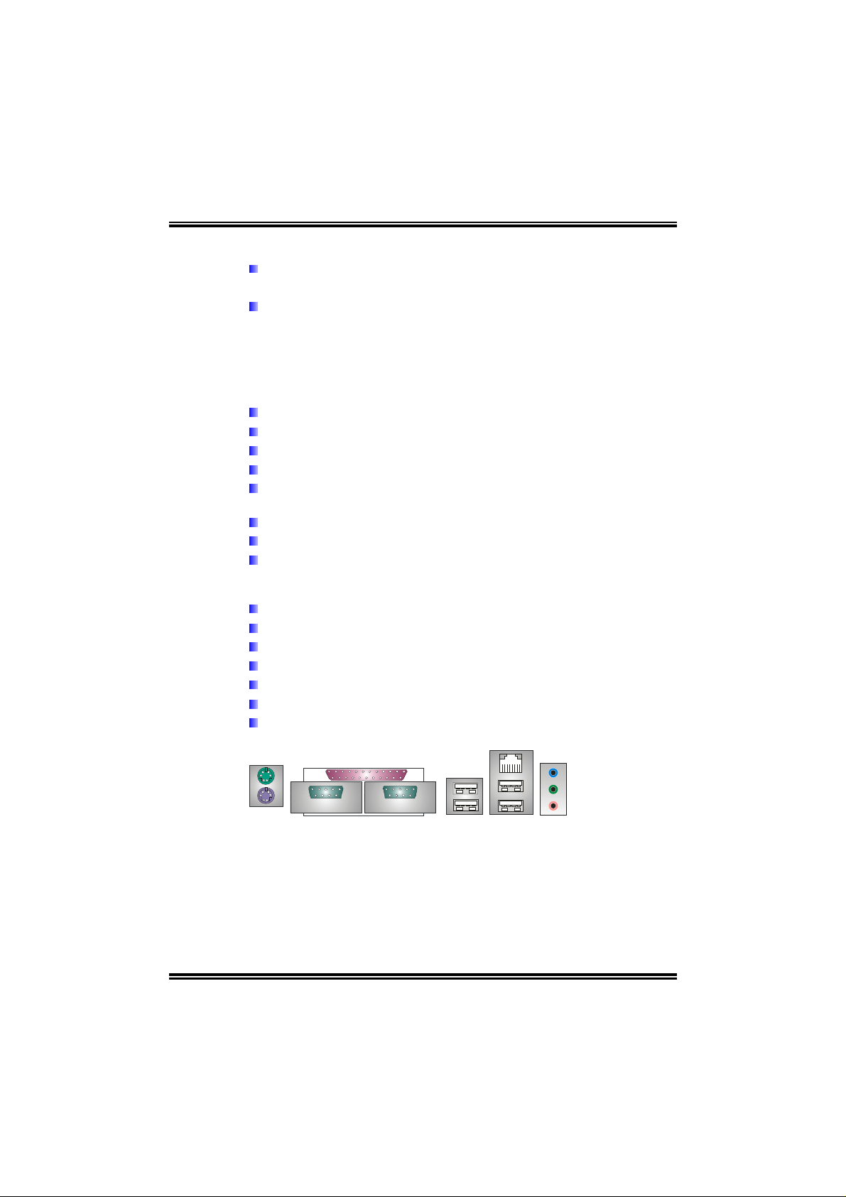
Rear (Back Panel) Side Connectors
1 PS/2 Mouse Port.
1 PS/2 Keyboard Port.
1 Printer Port.
1 Serial Port. (JCOM2 is optional.)
1 RJ-45 LAN jack.
4 USB 2.0 Ports.
3 audio ports support 6 channels audio-out facilities.
PS/2
Mouse
PS/2
Keyboard
COM1
JCOM1
Printer Port
COM2
(optional)
JCOM2
(optional)
JUSB1
USB *2
LAN
Connector
USB *2
Line-in/Rear
Line-out
MIC-in/
Center/
Left
3
Page 6

NF4-A9A / NF4 Ultra-A9A
B. BIOS & Software
BIOS
Award legal BIOS.
Supports APM1.2.
Supports ACPI.
Supports USB Function.
Bundled Software
Supports 9th Touch™, WINFLASHER™ and FLASHER™.
1.2 PACKAGE CHECKLIST
FDD Cable X 1
HDD Cable X 1
User’s Manual X 1
Serial ATA Cable X 1
Fully Setup Driver CD X 1
Rear I/O Panel for ATX Case X 1
USB 2.0 Cable X1 (optional)
S/PDIF Cable X 1 (optional)
Serial ATA Power Switch Cable X 1 (optional)
4
Page 7
NF4-A9A / NF4 Ultra-A9A
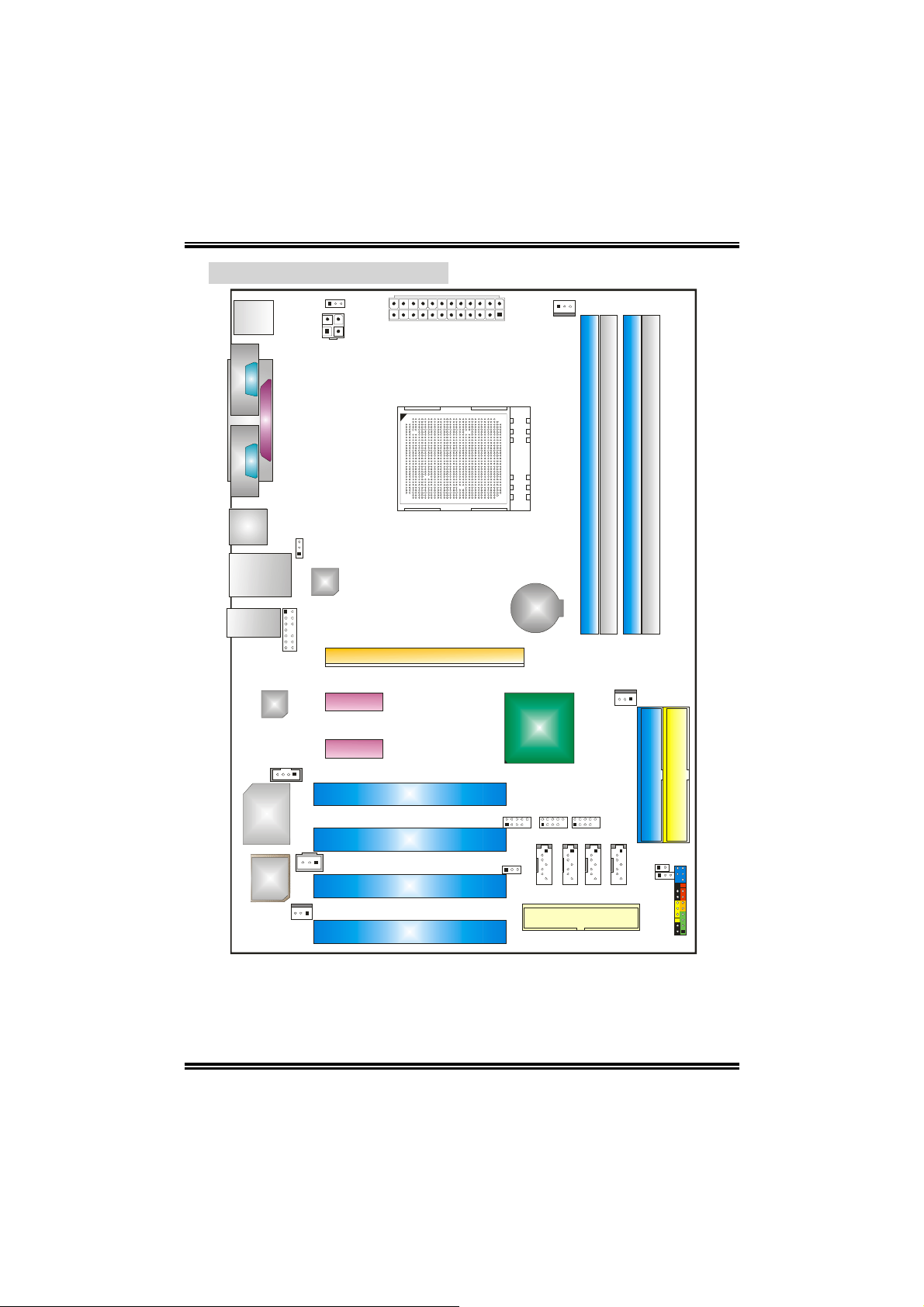
1.3 LAYOUT & COMPONENTS
JKBMSV1
JKBMS1
JCOM1
(optional)
JCOM2
JATXPWR2
JPRNT1
JATXPWR1
JCFAN1
Socket 939
DIMM1
DIMM2
DIMM3
DIMM4
JUSB1
JUSBLAN1
JAUDI O2
Codec
JCDIN1
Supe r I/O
JUSBV1
LAN
JAUDIO1
PEX1_1
PEX1_2
JSPDIF_OUT
BIOS
JSFAN1
Note: ■ represents the 1
st
pin.
PCI1
PCI2
PCI3
PCI4
PEX16
BAT1
nForce4
or
nForce4 Ultra
JUSB3 JUSB4JUSB2
JSATA1
JUSBV2
JSAT A2
FDD1
JSAT A3
JNBFAN1
JSAT A4
IDE1
JCI1
JCMOS1
JPANEL1
IDE2
5
Page 8
NF4-A9A / NF4 Ultra-A9A
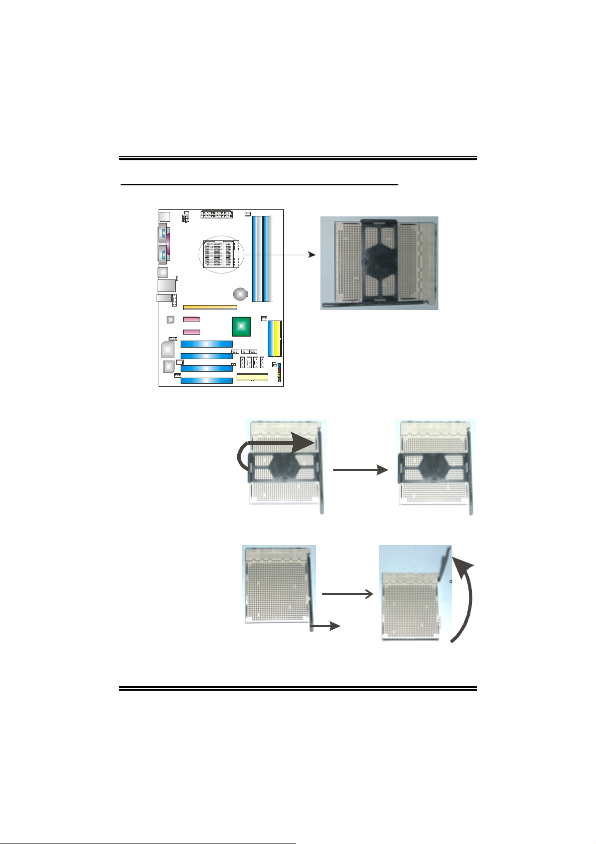
CHAPTER 2: HARDWARE INSTALLATION
2.1 CENTRAL PROCESSING UNIT (CPU)
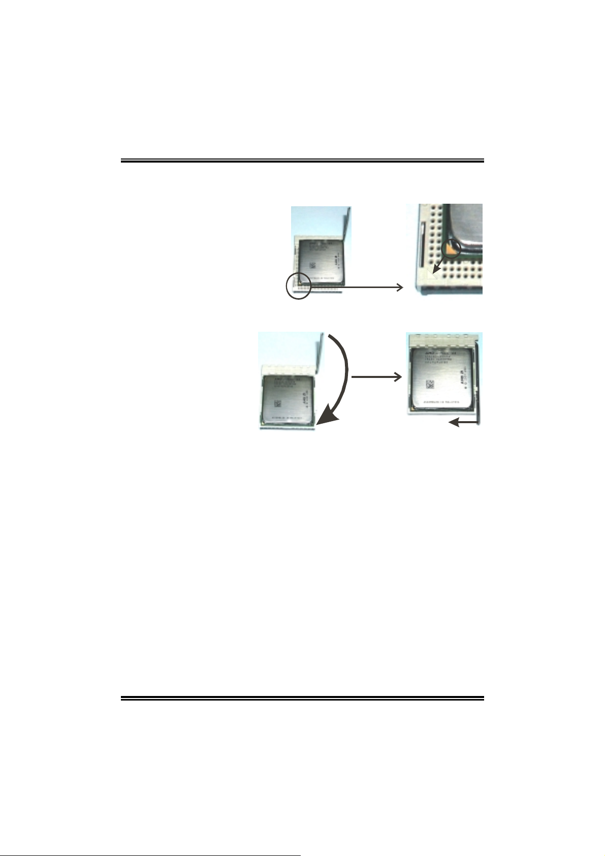
Step 1: Remove the socket protection cap.
Step 2: Pull the lever t ow ard directi on A from the socket and then raise the lever up
to a 90-degree angle.
90
A
6
Page 9
NF4-A9A / NF4 Ultra-A9A
Step 3: Look for the white triangle on socket, and the gold triangle on CPU should
point forwards this white triangle. The CPU will fit only in the correct
orientation.
Step 4: Hold the CPU down firmly, and then close the lever toward direct B to
complete the installation.
B
Step 5: Put the CPU Fan on the CPU and buckle it. Connect the CPU FAN power
cable to the JCFAN1. This completes the inst al lation.
7
Page 10
NF4-A9A / NF4 Ultra-A9A
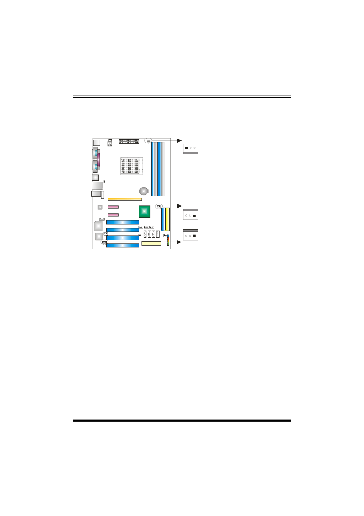
2.2 FAN HEADERS
CPU FAN Power Header: JCFAN1
System Fan Power Header: JSFAN1
Northbridge Fan Power Header: JNBFAN1
JCFAN1
JNBFAN1
13
13
13
Pin Assignment
1 Ground
2 +12V
3 FAN RPM rate sense
(Only for JCFAN1 and
JSFAN1.)
JSFAN1
Note:
The JCFAN1 and JSFAN1 reserve system cooling fan with Smart Fan Control utility. It
supports 3 pin head connector. When connecting with wires onto connectors, please note
that the red wire is the positive and should be connected to pin#2, and the black wire is
Ground and should be connected to GND.
8
Page 11
NF4-A9A / NF4 Ultra-A9A
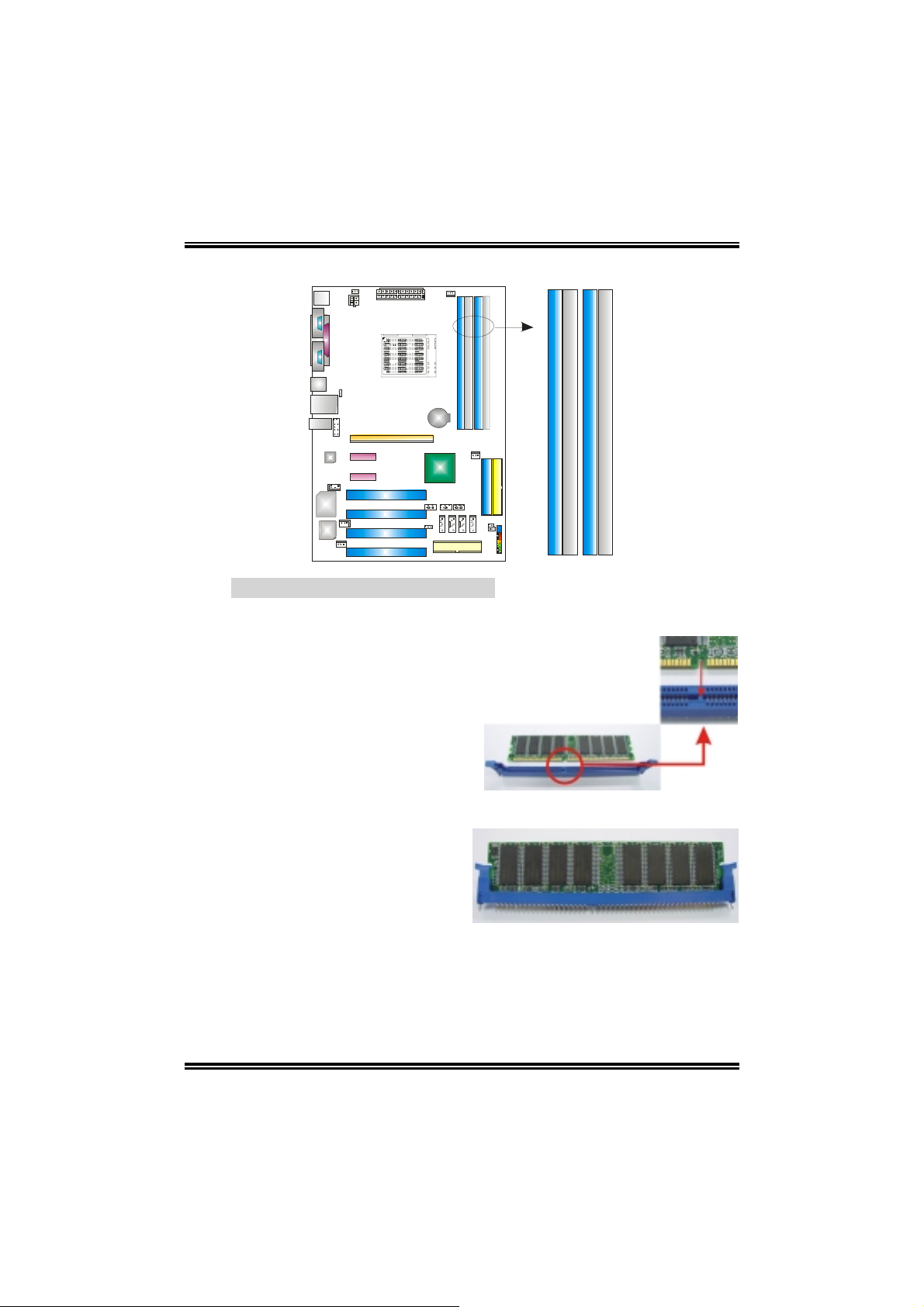
2.3 MEMORY MODULES INSTALLATION
DIMM3
DIMM1
DIMM4
DIMM2
2.3.1 DDR Module installation
1. Unlock a DIMM slot by pressing the retaining clips outward. Align a DIMM on
the slot such that the notch on the DIMM matches the break on the Slot.
2. Insert the DIMM vertically and firmly into the slot until the retaining chip snap
back in place and the DIMM is properly seated.
9
Page 12
NF4-A9A / NF4 Ultra-A9A
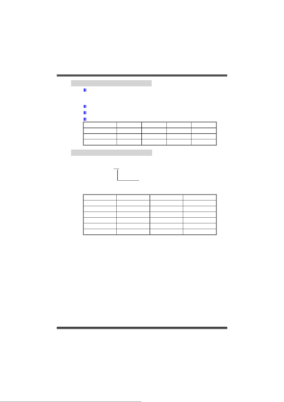
2.3.2 DDR Installation Notice:
For AMD K8 939 CPU launched before Rev. E, please follow the table
below to insta ll DD R memory module, or the system may no t boot up or
may not function properly. (Please refer to Table 1 for CPU Revision)
“SS” represents Single Side DDR memory module.
“DS” represents Double Side DDR memory module.
Star sign “*” represents leave the DIMM socket empty.
DIMM1 SS/DS
DIMM2
DIMM3
DIMM4
* * *
*
* * *
*
SS/DS SS/DS SS/DS
SS/DS SS/DS
2.3.3 Know your CPU Version
AMD Athlon™ 64 Processor Ordering Part Number Example
ADA 3200 A E P 5 AP
Table 1: AMD Athlon
Part Definition Revision Part Definition Revision
AP Rev C0 BI Rev D0
AR Rev CG BN Rev E4
AS Rev CG BP Rev E3
AW Rev CG BO Rev E3
AX Rev CG BY Rev E6
AZ Rev CG BW Rev E6
Part Definition: AP = Rev C0 (see T able 1)
™™™™
64 Processor Part Definition
SS/DS
SS/DS
10
Page 13
NF4-A9A / NF4 Ultra-A9A
2.4 CONNECTORS & SLOTS
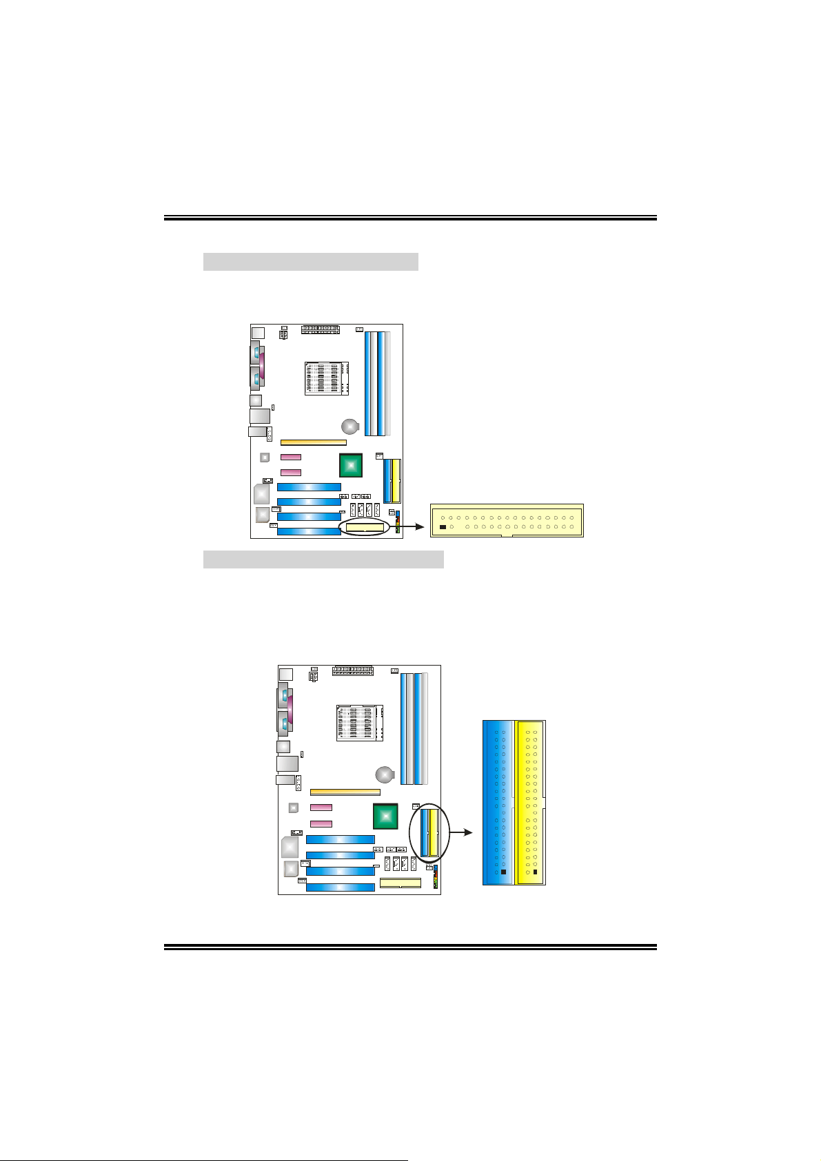
Floppy Disk Connector: FDD1
The motherboard provides a standard floppy disk connector that supports
360K, 720K, 1.2M, 1.44M and 2.88M floppy disk types. This connector
supports the provided floppy drive ribbon cables.
2
1
34
33
Hard Disk Connectors: IDE1/IDE2
The motherboard has two 32-bit Enhanced PCI IDE Controller that provides
PIO Mode 0~4, Bus Master, and Ultra DMA 33/66/100/133 functionality. It
has two HDD connectors IDE1 (primary) and IDE2 (secondary). The IDE
connectors can connect a master and a slave drive, so you can connect up
to four hard disk drives. The first hard drive should always be connected to
IDE1.
IDE2IDE1
40
2
39
1
11
Page 14
NF4-A9A / NF4 Ultra-A9A
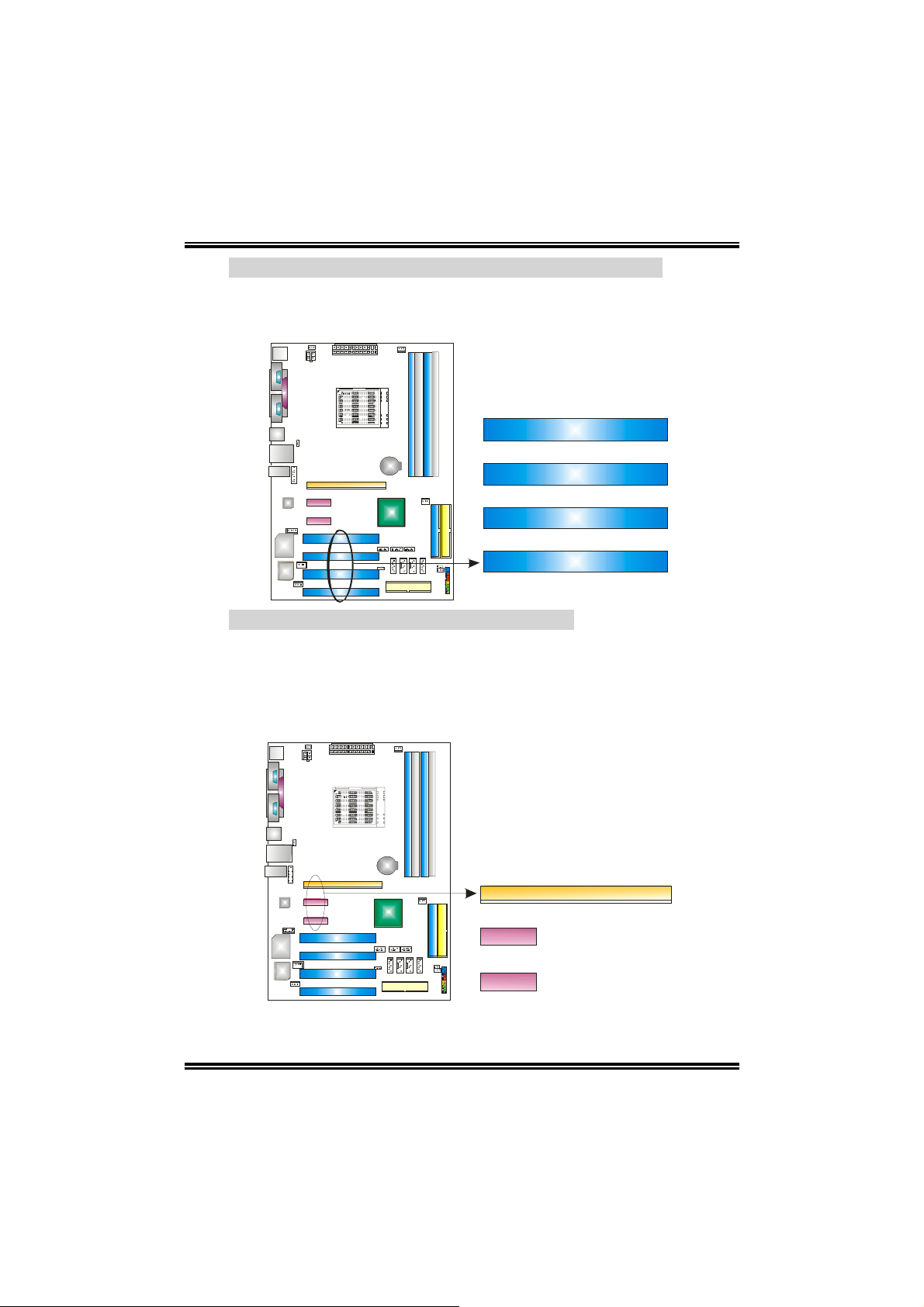
Peripheral Component Interconnect Slots: PCI1~PCI4
This motherboard is equipped with 4 standard PCI slots. PCI stands
for Peripheral Component Inter c onn ec t, and it is a bus standard for
expansion cards. This PCI slot is designated as 32 bits.
PCI1
PCI2
PCI3
PCI4
PCI-Express Slots: PEX16/PEX1_1/PEX1_2
PEX16:
- PCI Express 1.0a compliant.
- Maximum bandwidth is up to 4GB/s per direction.
PEX1_1/PEX1_2:
- PCI Express 1.0a compliant.
- Maximum bandwidth is up to 250MB/s per direction.
12
PEX16
PEX1_1
PEX1_2
Page 15
NF4-A9A / NF4 Ultra-A9A
CHAPTER 3: HEADERS & JUMPERS SETUP
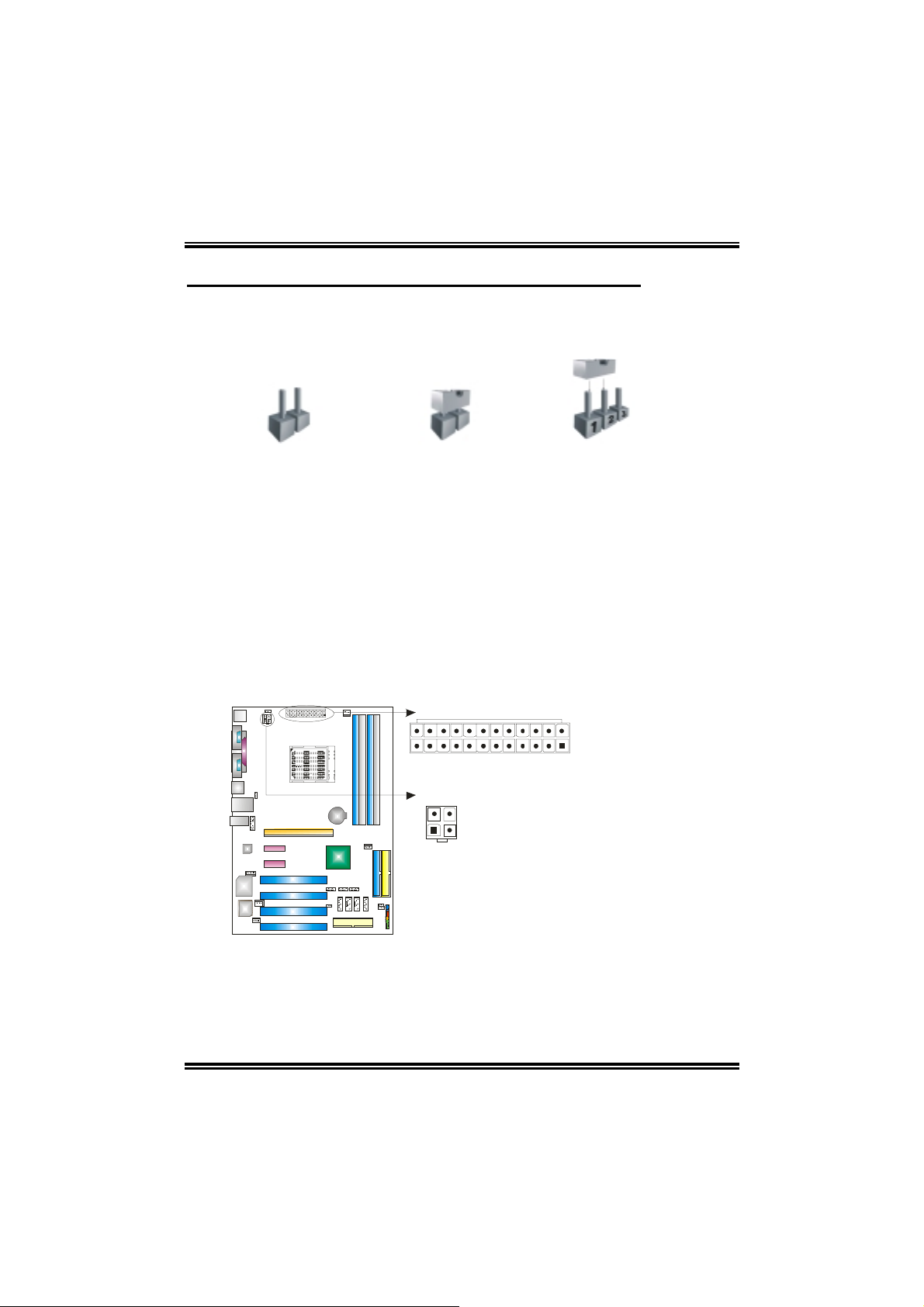
3.1 HOW TO SETUP JUMPERS
The illustration shows how to set up jumpers. When the jumper cap is placed on
pins, the jumper is “close”, if not, that means the jumper is “open”.
Pin opened Pin closed Pin1-2 closed
3.2 DETAIL SETTINGS
ATX Power Source Connectors: JATXPWR1/JATXPWR2
JATXPWR1: This connector allows user to connect 24-pin power connector on
the ATX power supply.
JATXPWR2: By connecting this connector, it will provide +12V to CPU power
circuit.
24
JATXPWR1
JATXPWR2
2
1
3
4
13
JATXPWR1:
Pin Assignment
1 +3.3V
2 +3.3V
3 Ground
4 +5V
5 Ground
6 +5V
7 Ground
8 PW_OK
13
9 Standby
112
10 +12V
11 +12V
12 Detect
13 +3.3V
14 -12V
15 Ground
16 PS_ON
17 Ground
18 Ground
19 Ground
20 -5V
21 +5V
22 +5V
23 +5V
24 Ground
JATXPWR2:
Pin Assignment
1 +12V
2 +12V
3 Ground
4 Ground
Voltage+5V
Page 16
NF4-A9A / NF4 Ultra-A9A
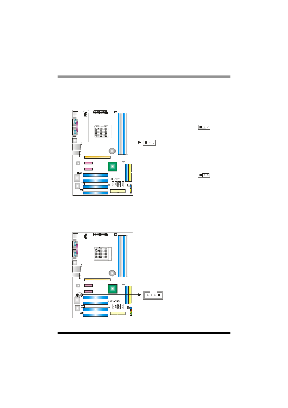
Power Source Header for PS/2 Keyboard/Mouse: JKBMSV1
Pin 1-2 Close: +5V for PS/2 keyboard and mouse.
Pin 2-3 Close: PS/2 keyboard and mouse are powered with +5V standby
voltage.
13
Pin 1-2 Close
(Default)
13
13
Pin 2-3 Close
Note: In order to support this function “Power-on system via keyboard and mouse”,
“JKBMSV1” jumper cap should be placed on Pin 2-3.
CD-ROM Audio-in Connector: JCDIN1
This connector allows u ser to conn ect the audi o s ourc e fro m the v arie ty dev ice s,
like CD-ROM, DVD-ROM, PCI sound card, PCI TV turner card etc..
14
14
Pin Assignment
1 Left channel input
2 Ground
3 Ground
4 Right channel input
Page 17
NF4-A9A / NF4 Ultra-A9A
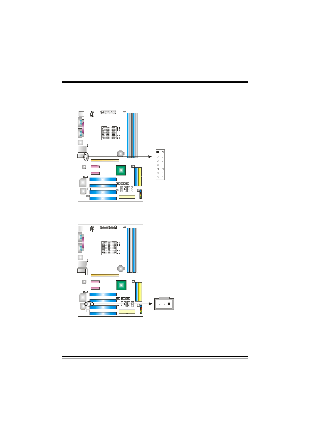
Front Panel Audio-out Header: JAUDIO1
This connector will allow user to connect with the front audio out put headers on
the PC case. It will disable the output on back panel audio connectors.
Pin Assignment
1 MIC-in/
Stereo MIC-in R
2 Ground
3 S tere o MIC-in L
4 Audio power
5 Right line-out/
Speaker-out Right.
2
1
14
13
6 Right line-out/
Speaker-out Right
7 Reserved
8 Key
9 Left line-out/
Speaker-out Left
10 Left line-out/
Speaker-out Left
11 Right line-in (optional)
12 Right line-in (optional)
13 Left line-in (optional)
14 Left line-in (optional)
Digital Audio-out Connector: JSPDIF_OUT
This connector allows user to connect the PCI bracket SPDIF output header.
Pin Assignment
1 +5V
2 SPDIF OUT
3 Ground
15
13
Page 18
NF4-A9A / NF4 Ultra-A9A
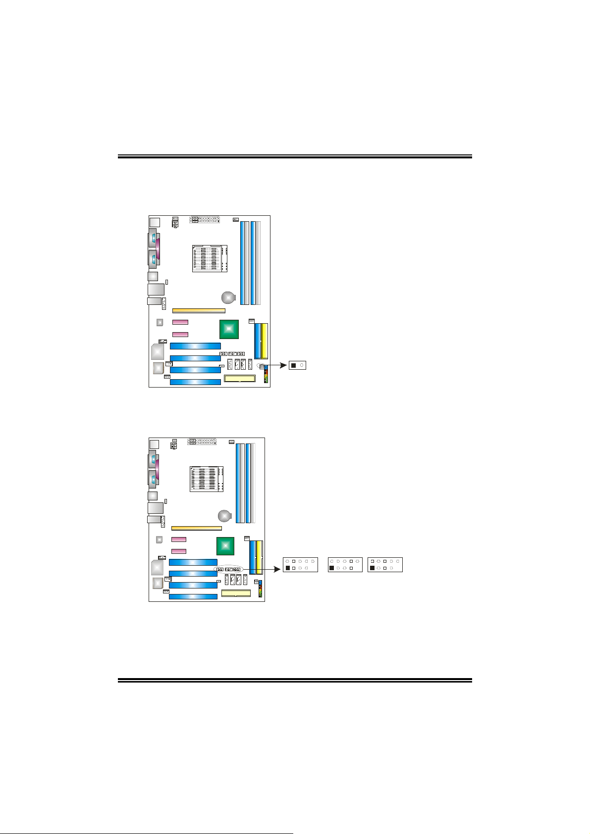
Case Open Header: JCI1
This connector allows system to monitor PC case open status. If the signal has
been triggered, it will record to the CMOS and show the message on next
boot-up.
Pin Assignment
1 Case open signal
2 Ground
12
Headers for USB Ports at Front Panel: JUSB2~JUSB4
This connector allows user to connect additional USB cables at PC front panel,
and also can be connected with internal USB devices, like USB card reader.
JUSB3 JUSB4JUSB2
10
2
10
2
2
Pin Assignment
1 +5V (fused)
2 +5V (fused)
3 USB4 USB5 USB+
6 USB+
7 Ground
8 Ground
9 Key
10 NC
10
9
1
9
1
9
1
16
Page 19
NF4-A9A / NF4 Ultra-A9A
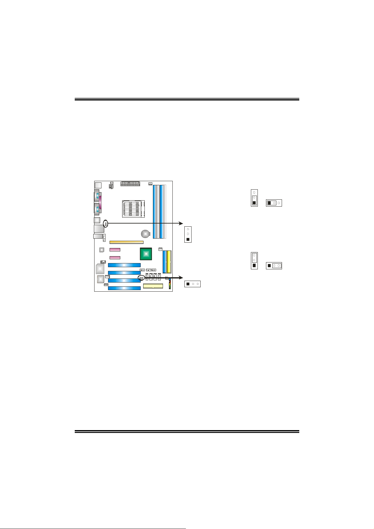
Power Source Headers for USB Ports: JUSBV1/JUSBV2
Pin 1-2 Close:
JUSBV1: +5V for USB ports at JUSB1 and JUSBLAN1.
JUSBV2: +5V for front USB headers (JUSB2/JUSB3/JUSB4).
Pin 2-3 Close:
JUSBV1: USB ports at JUSB1 and JUSBLAN1 are powered with +5V standby
voltage.
JUSBV2: Front USB headers (JUSB2/JUSB3/JUSB4) are powered with +5V
standby voltage.
JUSBV1
3
1
JUSBV2
13
3
1
Pin 1-2 Close
(Default)
3
1
Pin 2-3 Close
3
1
3
1
Note:
In order to support this function “Power-on system via USB device,” “JUSBV1/JUSBV2”
jumper cap should be placed on Pin 2-3 individually.
17
Page 20

NF4-A9A / NF4 Ultra-A9A
Clear CMOS Header: JCMOS1
By placing the jumper on pin2-3, it allows user to restore the BIOS safe setting
and the CMOS data, please carefully follow the procedures to avoid damaging
the motherboard.
3
1
Pin 1-2 Close:
Normal Operation (Default).
13
Pin 2-3 Close:
Clear CMOS data.
3
1
Clear CMOS Procedures:
1. Remove AC power line.
2. Set the jumper to “Pin 2-3 Close”.
3. Wait for five seconds.
4. Set the jumper to “Pin 1-2 Close”.
5. Power on the AC.
6. Reset your desired password or clear the CMOS data.
18
Page 21

NF4-A9A / NF4 Ultra-A9A
Header for Front Panel Facilities: JPANEL1
This 24-pin connector includes Power-on, Reset, HDD LED, Power LED, Sleep
button, speaker and IrDA Connection. It allows user to connect the PC case’s
front panel switch functions.
optional
23
24
12
Pin Assignment Function Pin Assignment Function
1 +5V 2 Sleep control
3 N/A 4 Ground
5 N/A 6 N/A N/A
7 Speaker
9 HDD LED (+) 10 Power LED (+)
11 HDD LED (-)
13 Ground 14 Power button
15 Reset control
17 N/A 18 N/A
19 N/A 20 Key
21 +5V 22 Ground
23 IRTX
Speaker
Connector
Hard drive LED
Reset button
IrDA Connector
(optional)
8 Power LED (+)
12 Power LED (-)
16 Ground
24 IRRX
Sleep button
Power LED
Power-on
button
IrDA Connector
(optional)
19
Page 22

NF4-A9A / NF4 Ultra-A9A
Serial ATA Connectors: JSATA1~JSATA4
The motherboard has a SATA Controller in nForce4 and nForce4 Ultra with 4
channels SATA interface, it satisfies the SATA 1.0 spec with transfer rate of
1.5Gb/s and SATA 2.0 spec with transfer rate of 3.0 Gb/s.
Pin Assignment
1 Ground
2 TX+
3 TX4 Ground
5 RX6 RX+
7 Ground
JSATA1
JSATA2
JSATA3
1
4
7
JSATA4
20
Page 23

NF4-A9A / NF4 Ultra-A9A
CHAPTER 4: USEFUL HELP
4.1 AWARD BIOS BEEP CODE
Beep Sound Meaning
One long beep followed by two short
beeps
High-low siren sound CPU overheated
One Short beep when system boot-up No error found during POST
Long beeps every other second No DRAM detected or install
4.2 EXTRA INFORMATION
A. BIOS Update
After you fail to update BIOS or BIOS is invaded by virus, the
Boot-Block function will help to restore BIOS. If the following message
is shown after boot-up the system, it means the BIOS contents are
corrupted.
Video card not found or video card
memory bad
System will shut down automatically
In this Case, please follow the procedure below to restore the BIOS:
1. Make a bootable floppy disk.
2. Download the Flash Utility “AWDFLASH.exe” from the Biostar
website: www.biostar.com.tw
3. Confirm motherboard model and download the respectively BIOS
from Biostar website.
4. Copy “AWDFLASH.exe” and respectively BIOS into floppy disk.
5. Insert the bootable disk into floppy drive and press Enter.
6. System will boo-up to DOS prompt.
7. Type “Awdflash xxxx.b f/sn/py/r” in DOS prompt.
8. System will updat e BIO S automatically and restart.
9. The BIOS has been recovered and will work properly.
21
Page 24

NF4-A9A / NF4 Ultra-A9A
B. CPU Overheated
If the system shutdown automatically after power on system for
seconds, that means the CPU protection function has been activated.
When the CPU is over heated, the motherboard will shutdown
automatically to avoid a damage of the CPU, and the system may not
power on again.
In this case, please double check:
1. The CPU cooler surface is placed evenly with the CPU surface.
2. CPU fan is rotated normally.
3. CPU fan speed is fulfilling with the CPU sp ee d.
After confirmed, please follow steps below to relief the CPU protection
function.
1. Remove the power cord from power supply for seconds.
2. Wait for seconds.
3. Plug in the power cord and boot up the system.
Or you can:
1. Clear the CMOS data.
(See “JCMOS1: Clear CMOS Header” section)
2. Wait for seconds.
3. Power on the system again.
22
Page 25

NF4-A9A / NF4 Ultra-A9A
4.3 TROUBLESHOOTING
Probable Solution
1. No power to the system at all
Power light don’t illuminate, fan
inside power supply does not
turn on.
2. Indicator light on keyboard does
not turn on.
System inoperative. Keyboard lights
are on, power indicator lights are lit,
and hard drive is spinning.
System does not boot from hard disk
drive, can be booted from optical drive .
System only boots from optical drive.
Hard disk can be read and applications
can be used but bootin g fro m hard d is k
is impossible.
Screen message says “Invalid
Configuration” or “CMOS Failure.”
Cannot boot system after installing
second hard drive.
1. Make sure power cable is securely
plugged in.
2. Replace cable.
3. Contact technical support.
Using even pressure on both ends of the
DIMM, press down firmly until t he modul e
snaps into place.
1. Check cable running from disk to
disk controller board. Make sure
both ends are securely plugged in;
check the drive type in the
standard CMOS setup.
2. Backing up the hard drive is
extremely important. All hard disks
are capable of breaking down at
any time.
1. Back up data and applicatio ns
files.
2. Reformat the hard drive. Re-install
applications and data using
backup disks.
Review system’s equipment. Make sure
correct information is in setup.
1. Set master/slave jumpers
correctly.
2. Run SETUP program and select
correct drive types. Call the drive
manufacturers for compatibility
with other drives.
23
Page 26

NF4-A9A / NF4 Ultra-A9A
CHAPTER 5: WARPSPEEDER™
5.1 INTRODUCTION
[WarpSpeeder™], a new powerful control utility, features three
user-friendly functions including Overclock Manager, Overvoltage
Manager, and Hardware Monitor.
With the Overclock Manager, users can easily adjust the frequency they
prefer or they can get the best CPU performance with just one click. The
Overvoltage Manager, on the other hand, helps to power up CPU core
voltage and Memory voltage. The cool Hardware Monitor smartly indicates
the temperatures, voltage and CPU fan speed as well as the chipset
information. Also, in the About panel, you can get detail descriptions about
BIOS model and chipsets. In addition, the frequency status of CPU,
memory, AGP and PCI along with the CPU speed are synchronically
shown on our main panel.
Moreover, to protect users' computer systems if the setting is not
appropriate when testing and results in system fail or hang,
[WarpSpeeder™] technology assures the system stability by automatically
rebooting the computer and then restart to a speed that is either the
original system speed or a suitable one.
5.2 SYSTEM REQUIREMENT
OS Support: Windows 98 SE, Windows Me, Windows 2000, Windows XP
DirectX: DirectX 8.1 or above. (The Windows XP operating system
includes DirectX 8.1. If you use Windows XP, you do not need to install
DirectX 8.1.)
24
Page 27

NF4-A9A / NF4 Ultra-A9A
5.3 INSTALLATION
1. Execute the setup execution file, and then the following dialog will pop
up. Please click “Next” button and follow the default procedure to
install.
2. When you see the following dialog in setup procedure, it means setup
is completed. If the “Launch the WarpSpeeder Tray Utility” checkbox
is checked, the Tray Icon utility and [WarpSpeeder™] utility will be
automatically and immediately launched after you click “Finish”
button.
Usage:
The following figures are just only for reference, the screen printed in
this user manual will change according to your motherboard on hand.
25
Page 28

NF4-A9A / NF4 Ultra-A9A
5.4 [WARPSPEEDER™] INCLUDES 1 TRAY ICON AND 5 PANELS
1. Tray Icon:
Whenever the Tray Icon utility is launched, it will display a little tray
icon on the right side of Windows Taskbar.
This utility is responsible for conveniently invoking [WarpSpeeder™]
Utility. You can use the mouse by clicking the left button in order to
invoke [WarpSpeeder™] directly from the little tray icon or you can
right-click the little tray icon to pop up a popup menu as following
figure. The “Launch Utility” item in the popup menu has the same
function as mouse left-click on tray icon and “Exit” item will close
Tray Icon utility if selected.
26
Page 29

NF4-A9A / NF4 Ultra-A9A
2. Main Panel
If you click the tray icon, [WarpSpeeder™] utility will be invoked.
Please refer to the following figure; the utility’s first window you will
see is Main Panel.
Main Panel contains features as follows:
a. Display the CPU Speed, CPU external clock, Memory clock, AGP clock,
and PCI clock information.
b. Contains About, Voltage, Overclock, and Hardware Monitor Buttons for
invoking respective panels.
c. With a user-friendly Status Animation, it can represent 3 overclock
percentage stages:
Man walking→overclock percentage from 100% ~ 110 %
Panther running→overclock percentage from 110% ~ 120%
Car racing→overclock percentage from 120% ~ above
27
Page 30

NF4-A9A / NF4 Ultra-A9A
3. Voltage Panel
Click the Voltage button in Main Panel, the button will be highlighted
and the Voltage Panel will slide out to up as the following figure.
In this panel, you can decide to increase CPU core voltage and
Memory voltage or not. The default setting is “No”. If you want to get
the best performance of overclocking, we recommend you click the
option “Yes”.
28
Page 31

NF4-A9A / NF4 Ultra-A9A
4. Overclock Panel
Click the Overclock button in Main Panel, the button will be
highlighted and the Overclock Panel will slide out to left as the
following figure.
Overclock Panel contains the these feature s:
a. “–3MHz button”, “-1MHz button”, “+1MHz button”, and “+3MHz button”:
provide user the ability to do real-time overclock adjustment.
Warning:
Manually overclock is potentially dangerous, especially when the
overclocking percentage is over 110 %. We strongly recommend you
verify every speed you overclock by click the Verify button. Or, you can
just click Auto overclock button and let [WarpSpeeder™] automatically
gets the best result for you.
b. “Recovery Dialog button”: Pop up the following dialog. Let user select
a restoring way if system need to do a fail-safe reboot.
29
Page 32

NF4-A9A / NF4 Ultra-A9A
c. “Auto-overclock button”: User can click this button and
[WarpSpeeder™] will set the best and stable performance and
frequency automatically. [WarpSpeeder™] utility will execute a
series of testing until system fail. Then system will do fail-safe
reboot by using Watchdog function. After reboot, the
[WarpSpeeder™] utility will restore to the hardware default
setting or load the verified best and stable frequency according
to the Recovery Dialog’s setting.
d. “Verify button”: User can click this button and [WarpSpeeder™]
will proceed a testing for current frequency. If the testing is ok,
then the current frequency will be saved into system registry. If
the testing fail, system will do a fail-safe rebooting. After reboot,
the [WarpSpeeder™] utility will restore to the hardware default
setting or load the verified best and stable frequency according
to the Recovery Dialog’s setting.
Note:
Because the testing programs, invoked in Auto-overclock and Verify,
include DirectDraw, Direct3D and DirectShow tests, the DirectX 8.1 or
newer runtime library is required. And please make sure your display
card’s color depth is High color (16 bit) or True color (24/32 bit) that is
required for Direct3D rendering.
5. Hardware Monitor Panel
Click the Hardware Monitor button in Main Panel, the button will be
highlighted and the Hardware Monitor panel will slide out to left as
the following figure.
In this panel, you can get the real-time status information of your
system. The information will be refreshed every 1 second.
30
Page 33

NF4-A9A / NF4 Ultra-A9A
6. About Panel
Click the “about” button in Main Panel, the button will be highlighted
and the About Panel will slide out to up as the following figure.
In this panel, you can get model name and detail information in hints
of all the chipset that are related to overclocking. You can also get
the mainboard’s BIOS model and the Version number of
[WarpSpeeder™] utility.
31
Page 34

NF4-A9A / NF4 Ultra-A9A
Note:
Because the overclock, overvoltage, and hardware monitor features
are controlled by several separate chipset, [WarpSpeeder™] divide
these features to separate panels. If one chipset is not on board, the
correlative button in Main panel will be disa bled, but wi ll not int er f er e
other panels’ functions. This property can make [WarpSpeeder™]
utility more robust.
32
Page 35

NF4-A9A / N F4 Ultra-A9A
BIOS Setup
BIOS Setup....................... ........................ ........................ ........................ 1
1 Main Menu.....................................................................................................................3
2 Standard CMOS Features ......................... ....................................................................6
3 Advanced BIOS Features.... .. .. .... .. ... .. .... .. .. .. .... .. .. .. ..... .. .. .. .... .. .. .. ..... .. .. .. .... .. .. .. .... .. ... .... .. .9
4 Advanced Chipset Features.................... .......... ......... ........ .......... ......... ........ ........ .........13
5 Integrated Peripherals.............. ............................................................................. ......... 16
6 Power Management Setup .......... ... .. .. .... .. .. .. .... .. .. ... .... .. .. .. .... .. .. .. ..... .. .. .. .... .. .. .. .. .... .. ... ..21
7 PnP/PCI Configurations................................................................................................24
8 PC Health Status............................................................................................................26
9 Frequency/Voltage Control...........................................................................................27
i
Page 36

NF4-A9A / NF4 Ultra-A9A
BIOS Setup
Introduction
This manual discussed Award™ Setup program built into the ROM BIOS.
The Setup program allows users to modify the basic system configuration.
This special information is then stored in battery-backed RAM so that it
retains the Setup information when the power is turned off.
The Award BIOS™ inst alled in your computer syst em’s ROM (Read Only
Memory) is a custom version of an industry standard BIOS. This means that it
supports AMD processor input/output system. The BIOS provides critical
low-level support for standard devices such as disk drives and serial and
parallel ports.
Adding important has customized the Award BIOS™, but nonstandard,
features such as virus and password protection as well as special support for
detailed fine-tuning of the chipset contro lling the e ntire system.
The rest of this manual is intended to guide you through the process of
configuring yo ur system using Setup.
Plug and Play Support
These AWARD BIOS supports the Plug and Play Version 1.0A specification.
ESCD (Extended System Conf iguration Data) write is supported.
EPA Green PC Support
This AWARD BIOS supports Version 1.03 of the EPA Green PC
specification.
APM Support
These AWARD BIOS supports Version 1.1&1.2 of the Advanced Power
Management (APM) specification. Power management features are
implemented via the System Management Interrupt (SMI). Sleep and Suspend
power management modes are supported. Power to the hard disk drives and
video monitors can be managed by this AWARD BIOS.
ACPI Support
Award ACPI BIOS support Version 1.0 of Advanced Configuration and
Power interface specification (ACPI). It provides ASL code for power
management and device configuration capabilities as defined in the ACPI
specification, developed by Microsoft, Inte l and To s hiba .
1
Page 37

NF4-A9A / NF4 Ultra-A9A
PCI Bus Support
This AWARD BIOS also supports Version 2.1 of the Intel PCI (Peripheral
Component Interconnect) local bus specification.
DRAM Support
DDR SDRAM (Double Da ta Rate Sy nc hr o no us DRA M) are s uppo rt ed.
Supported CPUs
This AWARD BIOS supports the A MD CPU.
Using Setup
In general, you use the arrow keys to highlight items, press <Enter> to select,
use the <PgUp> and <PgDn> keys to change entries, press <F1> for help and
press <Esc> to quit. The following table provides more detail about how to
navigate in the Setup program by using the keyboard.
Keystro
ke
Up arrow Move to previous item
Down
arrow
Left
arrow
Right
arrow
Move
Enter
PgUp
key
PgDn
key
+ Key Increase the numeric value or make changes
- Key Decrease the numeric value or make changes
Esc key Main Menu – Quit and not save changes into CMOS
F1 key General help on Setup navigation keys
F5 key Load previous values from CMOS
F7 key Load the optimized defaults
F10 key Save all the CMOS changes and exit
Function
Move to next item
Move to the item on the left (menu bar)
Move to the item on the right (menu bar)
Move to the item you desired
Increase the numeric value or make changes
Decrease the numeric value or make changes
Status Page Setup Menu and Option Page Setup
Menu – Exit
Current page and return to Main Menu
2
Page 38

NF4-A9A / NF4 Ultra-A9A
1 Main Menu
Once you enter Award BIOS™ CMOS Setup Utility, the Main Menu will
appear on the screen. The Main Menu allows you to select from several setup
functions. Use the arrow keys to select among the items and press <Enter> to
accept and enter the sub-menu.
!! WARNING !!
The information about BIOS defaults on manual (Figure
1,2,3,4,5,6,7,8,9) is just for reference, please refer to the BIOS
installed on board, fo r update inform a tio n.
Figure 1: Main Menu
Standard CMOS Features
This submenu contains indus try standard configurable options.
Advanced BIOS Features
This submenu allows yo u to co nfigure enhanced features of the BIOS.
Advanced Chipset Features
This submenu allows you to configure spec ial chipse t features.
Integrated Peripherals
This submenu allows you to configure certain IDE hard drive options and
Programmed Input/ Output features.
3
Page 39

NF4-A9A / NF4 Ultra-A9A
Power Management Setup
This submenu allows yo u to co nf ig ure the power manageme nt fea tures.
PnP/PCI Configurations
This submenu allows you to configure certain “Plug and Play” and PCI
options.
PC Health Status
This submenu allows you to monitor the hardware of your system.
Frequency/ Voltage Control
This submenu allow s you to chan ge CPU V cor e Volta ge an d CP U/PCI cl ock.
(However, this function is strongly recommended not to use. Not
properly change the voltage and clock may cause the CPU or M/B
damage!)
Load Optimized Defaults
This selection allows you to reload the BIOS when the system is having
problems particularly with the boot sequence. These configurations are
factory settings optimized for this system. A confirmation message will be
displayed before defaults are set.
Set Supervisor Password
Setting the supervisor password will prohibit everyone except the supervisor
from making changes using the CMOS Setup Utility. You will be prompted
with to enter a password.
4
Page 40

NF4-A9A / NF4 Ultra-A9A
Set User Password
If the Supervisor Password is not set, then the User Password will function in
the same way as the Supervisor Password. If the Supervisor Password is
set and the User Password is set, the “User” will only be able to
configurations but will not be able to change them.
Save & Exit Setup
Save all configuration changes to CMOS(memory) and exit setup.
Confirmation message will be displayed before proceeding.
Exit Without Saving
Abandon all changes made during the current session and exit setup.
Confirmation message will be displayed before proceeding.
Upgrade BIOS
This submenu allows yo u to upg rade bio s.
5
Page 41

NF4-A9A / NF4 Ultra-A9A
2 Standard CMOS Features
The items in Standard CMOS Setup Menu are divided into 10 categories.
Each category in cludes no, on e or mor e than one s etup items. U se the arrow
keys to highlight the item and then use the<PgUp> or <PgDn> keys to select
the value you want in each item.
Figure 2: Standard CMOS Setup
6
Page 42

NF4-A9A / NF4 Ultra-A9A
Main Menu Selections
This table shows the selections that yo u can ma ke on the Main Menu.
Item Options Description
Date mm : dd : yy Set the system date.
Note that the ‘Day’
automatically
changes when you set
the date.
Time hh : mm : ss Set the system
internal clock.
IDE Primary
Master
IDE Primary
Slave
IDE Secondary
Master
IDE Secondary
Slave
Drive A
Drive B
Video EGA/VGA
Options are in
its sub menu.
Options are in
its sub menu.
Options are in
its sub menu.
Options are in
its sub menu.
360K, 5.25 in
1.2M, 5.25 in
720K, 3.5 in
1.44M, 3.5 in
2.88M, 3.5 in
None
CGA 40
CGA 80
MONO
Press <Enter> to
enter the sub menu of
detailed options
Press <Enter> to
enter the sub menu of
detailed options.
Press <Enter> to
enter the sub menu of
detailed options.
Press <Enter> to
enter the sub menu of
detailed options.
Select the type of
floppy disk drive
installed in your
system.
Select the default
video device.
7
Page 43

NF4-A9A / NF4 Ultra-A9A
Item Options Description
Halt On All Errors
No Errors
All, but
Keyboard
All, but
Diskette
All, but Disk/
Key
Base Memory N/A Displays the amount
Extended
Memory
Total Memory N/A Displays the total
N/A Displays the amount
Select the situation in
which
you want the BIOS to
stop
the POST process
and
notify you.
of
conventional memory
detected during boot
up.
of
extended memory
detected
during boot up.
memory
available in the
system.
8
Page 44

NF4-A9A / NF4 Ultra-A9A
3 Advanced BIOS Features
Figure 3. Advanced BIOS Setup
Cache Setup
These BIOS attempt to load the operating system from the device i n the sequence
selected in these items.
CPU Internal Cache
Depending on the CPU/chipset in use, you may be able to increase memory
access time with this option.
Enabled (default) Enable cache.
Disabled Disable cache.
External Cache
This option enables or disabl es “Level 2” secondary cach e on the CPU, which
may improve pe r form a nce.
The Choices: Enabled (default) Enable cache.
Disabled Disable cache.
9
Page 45

NF4-A9A / NF4 Ultra-A9A
Boot Seq & Floppy Setup
Hard Disk Boot Priority
These BIOS attempt to load the operating system from the device in the
sequence
The Choices: Pri. Master, P ri. Sl av e, S ec. M ast er, S ec, Sl av e, US BHDD0 , USB
HDD1, USB HDD2, and Bootable Add-in Cards.
First/ Second/ Third/ Boot Other Device
These BIOS attempt to load the operating system from the devices in the
sequence selected in these items.
The Choices: Floppy, LS120, HDD-0, SCSI, CDROM, HDD-1, HDD-2,
HDD-3, ZIP100, LAN, Disabled.
Swap Floppy Drive
For systems with two floppy drives, this option allows you to swap logical drive
assignments.
The Choices: Disabled (default), Enabled.
selected in these items.
10
Page 46

Boot Up Floppy Seek
Enabling this option will test the floppy drives to determine if they have 40 or 80
tracks. Disabling this option reduces the time it takes to boot-up.
The Choices: Enabled (default), Disabled.
Virus Warning
This option allows you to choose the Virus Warning feature that is used to protect
the IDE Hard Disk boot sector. If this function is enabled and an attempt is made to
write to the boot sector, BIOS will display a warning message on the screen and
sound an alarm bee p.
Disabled (default) Virus protection is disabled.
Enabled Virus protection is activated.
Quick Power On Self Test
Enabling this option will cause an abridged version of the Power On Self-Test
(POST) to execute after you power up the computer.
Enabled (default) Enable quick POST.
Disabled Normal POST.
Boot Up NumLock Status
Selects the NumLock. State after power on.
On (default) Numpad is number keys.
Off Numpad is arrow keys.
Gate A20 Option
Select if chipset or key boa r d co ntro ller should control Gate A20.
Normal A pin in the keyboard controller controls GateA20.
Fast (default) Lets chipset control Gate A20.
NF4-A9A / NF4 Ultra-A9A
Security Option
This option will enable only individuals with passwords to bring the system online
and/or to use the CMOS Setup Utility.
System A password is required for the system to boot and is also
Setup (default) A password is required to access the Setup Utility only.
This will only apply if passwords are set from the Setup main menu.
APIC MODE
Selecting Enabled enables APIC device mode reporting from the BIOS to the
operating system.
The Choices: Enabled (default), Disabled.
Note: If the CPU type is AMD 939 Dual Core, this item will be
always”Enabled”.
required to accessthe Setup Utility.
11
Page 47

NF4-A9A / NF4 Ultra-A9A
MPS Version Control For OS
The BIOS supports versio n 1.1 and 1.4 o f the Inte l multipro ce s s o r spec ific at ion.
Select version suppor ted by the operation system runni ng o n this computer.
The Choices: 1.4 (default), 1.1.
OS Select For DRAM > 64MB
A choice other than Non-OS2 is only used for OS 2 sy s tem s w ith mem o ry e xce eding
64MB.
The Choices: Non-OS2 (default), OS2.
Summary Screen Show
This item allows you to enable/ disable display the Summary Screen Show.
The Choices: Enabled (default), Disabled.
12
Page 48

NF4-A9A / NF4 Ultra-A9A
4 Advanced Chipset Features
This submenu allows you to configure the specific features of the chipset installed on your
system. This chipset manage bus speeds and access to system memory resources, such as
DRAM. It also coordinates communications with the PCI bus. The default settings that
came with your system have been optimized and therefore should not be changed unless you
are suspicious that the settings have bee n change d incorre c tly.
Figure 4. Advanced Chipset Setup
CPU Frequency
This item allows you to select the CPU Frequency.
The Choices: 200 (default), 201, 202…….300(Max=30 0) .
HT Frequency
This item allows you to select the HT Frequency.
The Choices: Auto (default),1x,2x,3x, 4x,5x.
HT Width
This item allows you to control the utilized width of the outgoing side of the
HyperTranspor t link.
The Choices:↓↓↓↓16 ↑↑↑↑16 (default), ↓8 ↑8, ↓16 ↑8, ↓8 ↑16.
Err94 Enh
This item allows you to enable/disable the “sequential Prufetch Feature” of K8
CPU.
The choices: Disabled (default), Enabled, Auto.
13
Page 49

DRAM Configuration
Timing Mode
DDR Timing Setting by SPD or ITEM.
The Choices: Auto (default), Manual.
Max Memclock (MHz)
Places an artificial memory cl oc k li mit on th e s yst em pr event ed fr om running faster
than this frequency.
The Choices: 200 (default), 166, 133, and 100.
CAS# Latency(Tcl)
This field specify the cas# latency, i.e. cas# to read data va lid.
The Choices: CL=2.5 (default), CL= 3.0, CL=2.0.
Min RAS# active ti me (Tras)
This field specifies the minimum RAS# active time. Typically -45-60 Nsec.
The Choices: 8T (default).
RAS# to CAS# Delay (Trcd)
This field specifies the RAS# to CAS# Delay to read/ write command to the same
bank. Typically -20 Nsec.
The Choices: 4T (default).
Row precharge Time (Trp)
This field specifies the Row precharge Time. Precharge to Active or Auto-Refresh
of the same bank. Typically 20-24 Nsec.
The Choices: 2T (default).
Row to Row delay (Trrd)
The Choices: 2T (default).
NF4-A9A / NF4 Ultra-A9A
14
Page 50

NF4-A9A / NF4 Ultra-A9A
CPU Spread Spectrum
The Choices: Center Spread (default) , Disabled.
SATA Spread Spectrum
This item allows you to disable \ enable the
The Choices: Disabled (default), Down Spread.
PCIE Spread Spectrum
This item allows you to disable \ enable the SATA spread spectrum function.
The Choices: Disabled (default), Down Spread .
SSE/SSE2 Instructions
The Choices: Enabled (default), Disabled.
System BIOS Cacheable
Selecting the “Disabl ed ” option allows caching of the syste m BIOS ROM at
F0000h-FFFFFh which can improve system performance. However, any
programs writing to this area of memory will cause conflicts and result in
system errors.
The Choices: Disabled (default), Enabl ed.
SATA spread spectrum function.
15
Page 51

NF4-A9A / NF4 Ultra-A9A
5 Integrated Peripherals
Figure 5. Integrated Peripherals
IDE Function Setup
If you highlight the literal “Press Enter” next to the “IDE Function Setup” label and
then press
the enter key, it will take you a submenu with the following options:
OnChip IDE Channel 0/1
The motherboard chipset contains a PCI IDE inter face w ith s uppo rt fo r two
IDE channels. Select “Enabled” to activate the first and/or second IDE
interface. Select “Disabled” to deactivate a n interface if you are going to
install a primary and/or se c ondary add-in IDE inter fa ce .
The Choices: Enabled (default), Disabled.
16
Page 52

Primary / Secondary /Master / Slave PIO
The IDE PIO (Progr am m ed Input / Output) fields le t yo u se t a PIO mo de ( 0-4 )
for each of the IDE devices that the onboard IDE interface supports. Mode s 0
to 4 will increase performance progressive ly. In Auto mode, the system
automatically determines the best mode for each device.
The Choices: Auto (default), Mode0, Mode1, Mode 2, Mo de 3, Mode4.
Primary / Secondary / Master / Slave UDMA
Ultra DMA/100 functionality can be implemented if it is supported by the
IDE hard drives in your system. As well, your operating environment
requires a DMA driver (Windows 95 OSR2 or a third party IDE bus master
driver). If your hard drive and your system software both support Ultra
DMA/100, select Auto to enable BIOS support.
The Choices: Auto (default), Disabled.
IDE DMA Transfer Access
The Choices: Enabled (default), Disabled.
Serial-ATA A
Enables support fo r Ser ia l- A TA A.
The Choices: Enabled (default), Disabled
Serial-ATA B
Enables support fo r Ser ia l- A TA B.
The Choices: Enabled (default), Disabled
IDE Prefetch Mode
The Choices: Enabled (default), Disabled.
RAID Config
NF4-A9A / NF4 Ultra-A9A
RAID Enable
The choices: Disabled (default), Enabled.
SATA A/B Primary RAID
The choices: Disabled (default), Enabled.
17
Page 53

NF4-A9A / NF4 Ultra-A9A
SATA A/B Secondary RAID
The choices: Disabled (default), Enabled.
Onboard Device
OnChip USB
This option should be enabled if your system has a USB installed on the
system board. You w ill nee d to disable this fea tur e if you a dd a higher
performance controller.
The Cho ices: V1. 1+V2. 0 (default), Disabled, V1.1
USB keyboard Support
Enables support fo r USB atta c hed key bo a rd.
The Choices: Disabled (default), Enabled
USB Mouse Support
Enables support fo r USB atta c he d mouse .
The Choices: Disabled (default), Enabled
AC97 Audio
This option allows you to contro l the onbo a rd A C97 a udio .
The Choices: Auto (default), Disabled.
MAC LAN
This option allows you to change the state of the onboard MAC LAN.
The Choices: Auto (default), Disabled.
Onboard LAN Boot ROM
This item allows you to enable or disable O nbo a rd LAN Boo t ROM.
The Choices: Disabled (default), Enabled.
Onboard 1394
This item allows you to enable or disable the Onbo a rd 1394 C o ntro ller.
The Choices: Enabled (default), Disabled.
18
Page 54

NF4-A9A / NF4 Ultra-A9A
Onboard IO/Address
Onboard FDC Controller
Select Enabled if your system has a floppy disk controller (FDC) installed
on the system board a nd yo u w i sh to use it. I f ins ta l l and FD C or the sy s tem
has no floppy drive, select Disable d in this fie l d.
The Choices: Enabled (default), Disabled.
Onboard Serial Port 1
Select an address and corresponding interrupt for the first and second serial
ports.
The Choices: Disabled, 3F8/IRQ4 (default), 2F8/I R Q 3, 3E8/I R Q4,
2E8/IRQ3, Auto.
Onboard Parallel Port
This item allows you to determine access onboard parallel port controller
with which I/O Address.
The Choices: 378/IRQ7 (default), 278/IRQ5, 3BC /IRQ7, Disabled.
Parallel Port Mode
The default value is SPP.
The Choices:
SPP (default) Using Parallel port as Standard Printer Port.
EPP Using Parallel Port as Enhanced Parallel Port.
ECP Using Parallel port as Extended Capabilities Port.
ECP+EPP Using Parallel port as ECP & EPP mode.
ECP Mode Use DMA
Select a DMA Channel for the port.
The Choices: 3 (default), 1.
19
Page 55

IDE HDD Block Mode
Block mode is also called block transfer, multiple commands, or multiple sector
read / write. If your IDE hard drive supports block mode (most new drives do),
select Enabled for automatic detection of the optimal number of block mode (most
new drives do), select Enabled for automatic detection of the optimal number of
block read / write per sector where t he drive can support.
The Choices: Enabled (default), Disabled.
NF4-A9A / NF4 Ultra-A9A
20
Page 56

NF4-A9A / NF4 Ultra-A9A
6 Power Management Setup
The Power Management Setup Menu allows you to configure your system to utilize energy
conservatio n a nd po wer up/power down fea tur e s .
Figure 6. Power Management Setup
ACPI function
This item displays the status of the Advanced Configuration and Power
Management (ACPI ).
The Choices: Enabled (default), Disabled.
ACPI Suspend Type
The item allows you to select the suspe nd ty pe under the ACPI operating system.
The Choices: S1 (POS) (default) Power on Suspend
S3 (STR) Suspend to RAM
S1+S3 POS+STR
21
Page 57

Power Management
This category allows you to select the type (or degree) of power saving and is
directly related to the following modes:
1. HDD Power Down.
2. Suspend Mode.
There are four options of Power Management, three of which have fixed mode
settings
Min. Power Saving
Minimum power ma nag e m ent.
Suspend Mode = 1 hr.
HDD Power Down = 15 min
Max. Power Saving
Maximum power ma nag e m e nt o nly av a ila ble for sl CPU’s.
Suspend Mode = 1 min.
HDD Power Down = 1 min.
User Define (default)
Allows you to set each mode individually.
When not disabled, each of the ranges is from 1 min. t o 1 hr. except for HDD
Power Down which ranges from 1 min. to 15 min. and disable.
Video Off Method
This option determines the manner in which the monito r is goes blank.
V/H SYNC+Blank
This selection will cause the system to turn off the vertical and horizontal
synchronization po rt s a nd w rite bla nk s to the v ide o buff er.
Blank Screen
This option only writes blanks to the video buffer.
DPMS (default)
Initial display power manageme nt signaling.
The Choices: Stop Grant, PwrOn Suspend.
HDD Power Down
When enabled, the hard disk drive will power down and after a set time of system
inactivity. All other devices remain active.
The Choices: Disabled (default), 1 Min, 2 Min, 3 Min, 4 Min, 5 Min, 6 Min, 7 Min,
8 Min, 9 Min, 10 Min, 11 Min, 12 Min, 13 Min, 14 Min, 15Min.
Soft-Off by PWR-BTTN
Pressing the power button for more than 4 seconds forces the system to enter the
Soft-Off state whe n the sys tem has “ hung . ”
The Choices: Delay 4 Sec, Instant-Off (default).
WOL (PME#) From Soft-Off
The Choices: Disabled (default), Enabled.
NF4-A9A / NF4 Ultra-A9A
22
Page 58

WOR (RI#) From Soft-Off
The Choices: Disabled (default), Enabled.
USB Resume from S3
The Choices: Disabled (default), Enabled.
Power-On by Alarm
When you select Enabled, an alarm returns the system to Full ON state.
The Choices: Disabled (default), Enabled.
Date (of Month) Alarm
You can choose which month the system will boot up.
Time (hh:mm:ss) Alarm
You can choose shat hour, minute and second the system will boot up.
Note: If you have change the setting, you must let the system boot up until it goes
to the operating system, before this function will work.
Power on Function
This option allows you to choose the different function to po wer on the com puter.
The Choices: Button Only (default), Pas s wor d, Mo use Mo ve , Mous e C lic k, A ny
Key, Hot Key, Keyboard 98.
NF4-A9A / NF4 Ultra-A9A
KB Power ON Password
Input password and press Enter to set the Keyboard power on password.
Hot Key Power on
This option allows you to choose a hot key to power on.
The Choices: Ctrl-F1 (default), Ctrl-F2, Ctrl-F3, Ctrl-F4, Ctrl-F5, Ctrl-F6, Ctrl-F7,
Ctrl-F8
POWER After PWR-Fail
This setting specifies whether your system will reboot after a power fail or
interrupts
occurs.
Off Leaves the computer in the power off state.
On Reboots the computer.
Former-Sts Restores the system to the status before power failure or interrupt
occurs.
The Choices: Off (default), On, Former-Sts.
23
Page 59

NF4-A9A / NF4 Ultra-A9A
7 PnP/PCI Configurations
This section describes configuring the PCI bus system. PCI, or Personal Computer
Interconnect, is a system which a llows I/O devices to operate at sp eeds nearing t he speed of
the CPU itself uses when communicating with its own special components. This section
covers some very technical items and it is strongly recommended that only experienced users
should make any changes to the default se ttings.
Figure 7. PnP/PCI Configurations
Init Display First
With systems that have multiple video cards, this option determines whether the
primary display use s a PCI Slo t or a n AGP Slot.
The Choices: PCI Slot (default), PCIEx Slot.
Resources Controlled By
By Choosing “Auto(ESCD)” (default), the system BIOS will detect the system
resources and automatically assign the relative IRQ and DMA channel for each
peripheral.By Choosing “Manual”, the user will need to assign IRQ & DMA for
add-on cards. Be sure tha t the re ar e no IR Q /D MA a nd I/ O po r t conflic ts .
24
Page 60

IRQ Resources
This submenu will allow you to assign each system interrupt a type, depending on
the type of device using the interrupt. When you press the “Press Enter” tag, you
will be directed to a submenu that will allow you to configure the system interrupts.
This is only configurable when “Resources Controlled By” is set to “Manual”.
PCI / VGA Palette Snoop
Choose Disabled or Enabled. Some graphic controllers which are not VGA
compatible take the output from a VGA controller and map it to their display as a
way to provide boot information and VGA compatibility.
However, the color information coming from the VGA controller is drawn from the
palette table inside the VGA controller to generate the proper colors, and the
graphic controller needs to know what is in the palette of the VGA controller. To
do this, the non-VGA graphic controller watch es for the Write access to the VGA
palette and registers the snoop data. In PCI based systems, where the VGA
controller is on the PC I bus and a non-VGA graphic controller is on an ISA bus, the
Write Access to the palette will not show up on the ISA bus if the PCI VGA
controller responds to the Write.
In this case, the PCI VGA controller should not respond to the Write, it should only
snoop the data and permit the access to be forwarded to the ISA bus. The
non-VGA ISA graphic controll er can then snoop the data on the ISA bus. Unless
you have the above situatio n, you should disable this optio n.
Disabled (default) Disables the function.
Enabled Enables the function.
Maximum Payload Size
Set the maximum payload size for Tran sact ion packets (TLP).
The Choice: 4096 (default),128,256,512,1024,2048.
NF4-A9A / NF4 Ultra-A9A
IRQ-3 assigned to PCI Device
IRQ-4 assigned to PCI Device
IRQ-5 assigned to PCI Device
IRQ-7 assigned to PCI Device
IRQ-9 assigned to PCI Device
IRQ-10 assigned to PCI Device
IRQ-11 assigned to PCI Device
IRQ-12 assigned to PCI Device
IRQ-14 assigned to PCI Device
IRQ-15 assigned to PCI Device
25
Page 61

NF4-A9A / NF4 Ultra-A9A
8 PC Health Status
Figure 8. PC Health Status
Chassis Open Warning
This item allows you to enable or disable Chassis Open Warning beep.
The Choices: Disabled (default), Enabled.
Shutdown Temperature
This item allows you to set up the CPU shutdown Temperature. This item only
effective under Windo ws 98 A CPI mo de .
The Choices: Disabled (default), 60 /140F, 65 /149F, 70 /158F .
CPU FAN Control by
The Choice “sma rt ” c a n make your C PU FA N to reduce noise.
The Choices: SMART, Always On (default).
Show H/W Monitor in POST
If your computer contains a monitoring system, it will show PC health status during
POST stage. The item offers several delay time for you to choose.
The Choices: Enabled (default), Disabled.
CPU Vcore,NB/SB Volt,+3.3V,+5.0V, +12.0V, 5V(SB),Voltage Battery
Detect the system’s voltage status automatically.
CPU Temperature
This field displays the current temperature of the CPU.
Current CPU FAN Speed
This field displays the current speed of CPU fan.
Current SYS FAN Speed
This field displays the curre nt spee d SYSTEM fan.
26
Page 62

NF4-A9A / NF4 Ultra-A9A
9 Frequency/Voltage Control
Figure 9. Frequency/Voltag e Control
Hammer Fid Co ntrol
This item allows you to select Hammer Fid Control.
The Choices: StartUp (default), X4 800MHz, X5 1000MHz, X6 1200MHz, X7
1400MHz, X8 1600MH z, X 9 1800MH z, etc.
Hammer Vid Control
This item allows you to select Hammer Vid Control.
The Choices: StartUp (default),1.725V , 1.700V,1.675, 1. 650,1.625 , etc.
DDR Voltage Regulator
This item allows you to select DDR Voltage Control.
The Choices: Default (default), 2.70V, 2. 80V , 2.90V.
27
 Loading...