

Page 1

MCP6P3/N68S3 BIOS Manual
i
B IOS Set up.... ............ ............ ............ ............ ............ ............ ............ .........1
1 Main Menu...............................................................................................3
2 Adv anc ed Menu...... ............ ............ ............ ............ ............ ............ .........7
3 PCIPnP Me nu........................................................................................18
4 Boot Menu..............................................................................................22
5 Chipset Menu.........................................................................................24
6 Performance Menu...............................................................................29
7 Exit Menu...............................................................................................34
Page 2

MCP6P3/N68S3 BIOS Manual
BIOS Setup
Introduction
The purpose of this manual is to describe the settings in the AMI BIOS Setup
program on this motherboard. The Setup program allows users to modify the basic
system configuration and save these settings to CMOS RAM. The power of CMOS
RAM is supplied by a battery so that it retains the Setup information when the power
is turned off.
Basic Input-Output System (BIOS) determines what a computer can do without
accessing programs from a disk. This system controls most of the input and output
devices such as keyboard, mouse, serial ports and disk drives. BIOS activates at the
first stage of the booting process, loading and executing the operating system. Some
additional features, such as virus and password prot ection or chipset fine-tuning
options are also included in BIOS.
The rest of this manual will to guide you through the options and settings in BIOS
Setup.
Plug and Play Support
This AMI BIOS supports the Plug and Play Version 1.0A specification.
EPA Green PC Support
This AMI BIOS supports Version 1.03 of the EPA Green PC specification.
APM Support
This AMI BIOS supports Version 1.1&1.2 of the Advanced Power Management
(AP M) speci ficat ion. Power m anagement fe atures a re i mplemented via t he S yst em
Management Int errupt (SMI). Sleep and Suspend power management modes are
supported. Power to the hard disk drives and video monitors can also be managed by
this AMI BIOS.
ACPI Support
AMI ACP I BIOS support Version 1.0/2.0 of Advanced Configuration and Power
interface specifi cation (ACPI). It provides ASL code for power management and
device con figuration capabilities as defined in the ACPI specification, developed by
Microsoft, Intel and T oshiba.
1
Page 3
MCP6P3/N68S3 BIOS Manual
PCI Bus Support
This AMI BIOS also supports Version 2.3 of the Intel PCI (Peripheral Component
Int erconn ect ) local bus speci ficati on .
DRAM Sup port
DDR3 S DRAM (Double Data Rate III Synchronous DRAM) is supported.
Su ppor t e d CP Us
This AMI BIOS supports the AMD CPU.
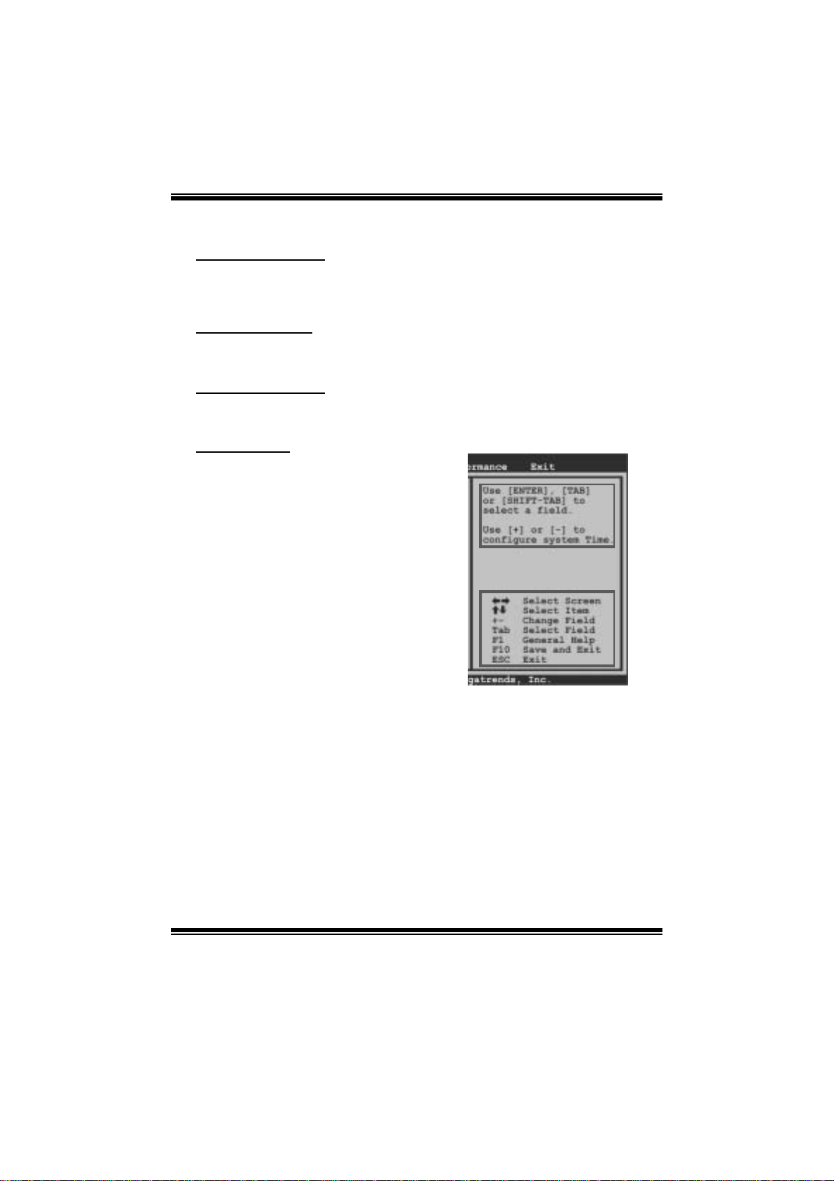
Using Setup
W hen st arting up the computer, press
<Del> during the Power-On Self-Test
(POST) to enter the BIOS setup utility.
In the BIOS setup utility, you will see
General Help description at the top right
corner, and this is providing a brief
description of the selected item.
Navigation Keys for that particular menu
are at the bottom right corner, and you can
use these keys to sele ct item and ch ange
the settings.
Notice
z The default BIOS settings apply for most conditions to ensure optimum performance
of the motherboard. If the system becomes unstable after changing any settings,
please load the default settings to ensure system’s compatibility and stability. Use
Load Setup Default under the Exit Menu.
z For better system performance, the BIOS firmware is being continuously updated.
The BIOS information described in this manual is for your refer ence only. The actual
BIOS information and settings on board may be slightly different from this manual.
z The content of this manual is subject to be changed without notice. We will not be
responsible for any mistakes found in this user’s manual and any system damage that
may be caused by wrong-settings.
General Help
Navigation Keys
2
Page 4

MCP6P3/N68S3 BIOS Manual
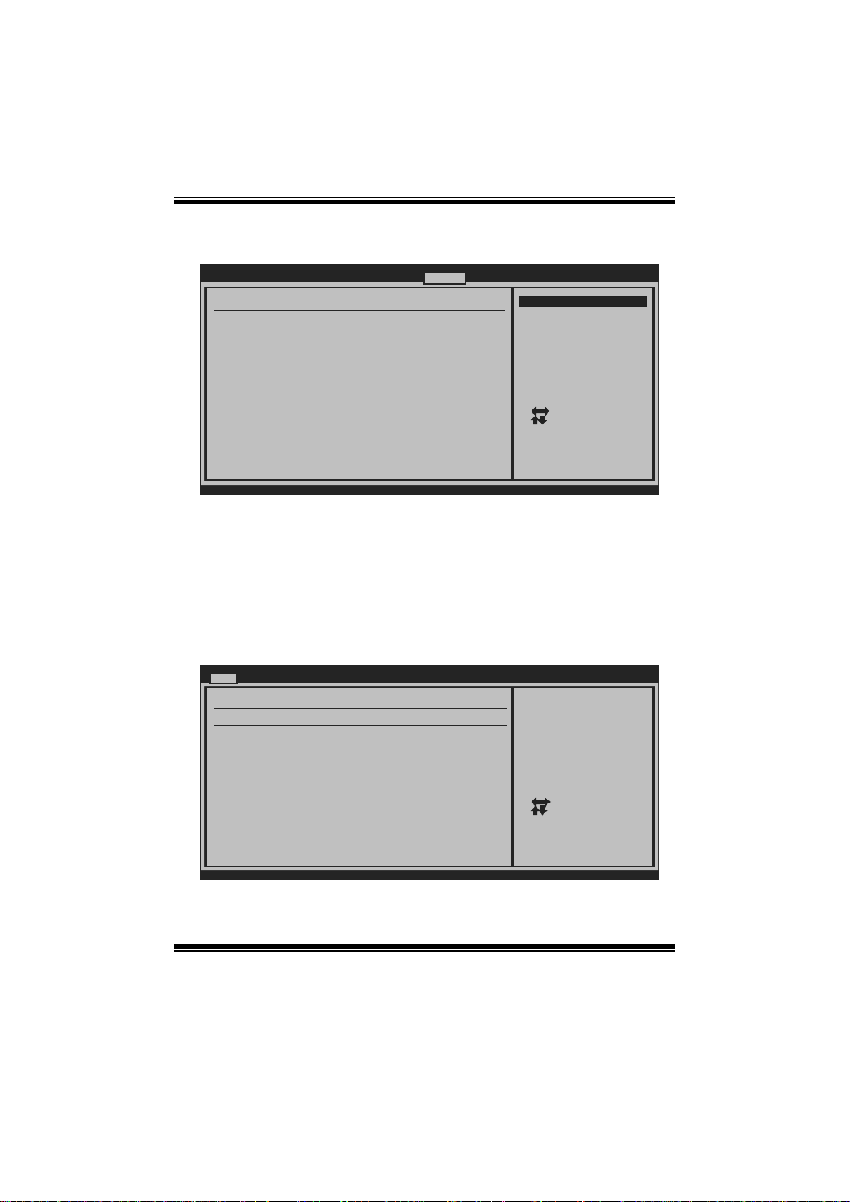
1 Main Menu
Once you enter AMI BIOS Setup Utility, the Main Menu will appear on the screen
providing an overview of the basic system inform ation.
Main Advanced PCIPnP Boot Chipset Performance
System Overview
AMI BIOS
Version :01.01.01
Build Date:01/01/09
System Memory
Size :
System Time [ :00:00]00
System Date [Thu 01/01/2009]
Floppy A
> IDE Configuration
vxx.xx (C)Copyright 1985-200x, Amer ican Megatre nds, Inc.
AM I BI O S
BIOS SETUP UTILITY
Exit
Use [ENTER], [TA B]
or [SHIFT-TAB] to
select a field.
Use [+] or [-] to
configure system Time.
Select Screen
Select Item
Change Field
+-
Select Field
Tab
General Help
F1
Save and Exit
F10
Exit
ESC
Shows system information including BIOS version and built date.
System Memory
Shows system memory size, VGA shard memory will be excluded..
System Ti me
Set the system internal clock.
System Date
Set the system date. Note that the ‘Day’ automatically changes when you set the
date.
Floppy A
Select the type of floppy disk drive installed in your system.
Options: 360K, 5.25 in / 1.2M, 5.25 in / 720K, 3.5 in / 1.44M, 3.5 in /
2.88M, 3.5 in / None
3
Page 5

MCP6P3/N68S3 BIOS Manual
IDE Configuratio n
T he BIOS will automat ically detect the presence of IDE/SAT A devices. There i s a
sub-menu for each IDE/S AT A devi ce. S elect a device and press <Enter> to enter
the sub-menu of detailed options.
Main
IDE Configuration
OnBoard IDE Controller [ Enabled]
Serail-ATA Devices [ Device 0/1]
> nVidia RAID Setup
> Primary IDE Master
> Primary IDE Slave
> SATA 1 Device
> SATA 2 Device
> SATA 3 Device
> SATA 4 Device
Hard Disk Write Protect [ Disabled]
IDE Detect Time Out (Sec) [ 35]
BIOS SETUP UTILITY
DISABLED: disables the
integrated IDE
Controller.
ENABLED: enables the
integrated IDE
Controller.
Select Screen
Select Item
Go to Sub Screen
Enter
General Help
F1
Save and Exit
F10
Exit
ESC
vxx.xx (C)Copyright 1985-200x, Amer ican Megatre nds, Inc.
OnBoar d I DE Controller
This item allows you to control the onboard IDE controller.
Options: Enhanced (Default) / Disabled
S erial - A TA De v i ces
This item allows you to choose SATA Devices.
Options: Device 0/1 (Default) / Device 0 / Disabled
4
Page 6
MCP6P3/N68S3 BIOS Manual
nVidia RAID Setup
BIOS SETUP UTILITY
RAID Setup
nVidia RAID Function [ Disabled]
SATA 1 Raid [ Disabled]
SATA 2 Raid [ Disabled]
SATA 3 Raid [ Disabled]
SATA 4 Raid [ Disabled]
Chipset
Options
Dis
abled
Enabled
Select Screen
Select Item
Update
Enter
General Help
F1
Save and Exit
F10
Exit
ESC
vxx.xx (C)Copyright 1985-200x, Amer ican Megatre nds, Inc.
nVidia RAID Function
This item allows you to activate RAID function.
Options: Disabled (Default) / Enabled
SA TA 1/2/3/ 4 Raid
Enable or disable RAID fun ction of SATA devices.
Options: Disabled (Default) / Enabled
Primary IDE Master/Slave ; SATA 1/2/3/4 Device
Main
Primary IDE Master
Device :
Type [Auto]
LBA/Large Mode [Auto]
Block (Multi-Sector Transfer)[Auto]
PIO Mode [Auto]
DMA Mode [Auto]
S.M.A.R.T [Auto]
32Bit Data Transfer [Enabled]
vxx.xx (C)Copyright 1985-200x, American Megatrends, Inc.
BIOS SETUP UTILITY
Select the type
of device connected
to the system.
Select Screen
Select Item
Change Option
+-
General Help
F1
Save and Exit
F10
Exit
ESC
5
Page 7

MCP6P3/N68S3 BIOS Manual
T he BIOS detects the inform ation and values of resp ecti ve devi c es, and these
information and values are shown below to the name of the sub-menu.
Type
Select the type of the IDE/SATA drive.
Options: Auto (Default) / CDROM / ARMD / Not Installed
LBA/Large Mode
Enable or disable the LBA mode.
Options: Auto (Default) / Disabled
Block (Multi-Sector Transfer)
Enable or dis able multi-sector trans fer.
Options: Auto (Default) / Disabled
PIO Mode
Select the PIO mode.
Options: Auto (Default) / 0 / 1 / 2 / 3 / 4
DMA Mode
Select the DMA mode.
Options: Auto (Default) / S WDMA0 ~ 2 / MWDMA0 ~ 2 / UDMA0 ~ 5
S.M.A.R.T
Set the Smart Monitoring, Analysis, and Reporting Technology.
Options: Auto (Default) / Disabled / Enabled
32Bit Data Transfer
Enable or disable 32-bit data transfer.
Options: Enabled (Default) / Disabled
Har d Disk Write Protect
Disable or enable device write protection. This will be effective only if the device
is accessed through BIOS.
Options: Disabled (Default) / Enabled
IDE Detect Time Out (Sec)
Select the time out value for detecting IDE/SATA devices.
Options: 35 (Default) / 30 / 25 / 20 / 15 / 10 / 5 / 0
6
Page 8

MCP6P3/N68S3 BIOS Manual
2 Advanced Menu
The Advanced Menu allows you to configure the settings of CPU, Super I/O, Power
Management, and other system devices.
Notice
z Beware of that setting inappropriate values in items of this menu may cause
system to malfunction.
Main Advanced PCIPnP Boot Chipset Performance
WARNING: Setting wrong values in below sec tions
may cause system to malfunction.
> CPU Configuration
> SuperIO Configuration
> Hardware Health Configuration
> Smart Fan Configuration
> Power Configuration
> USB Configuration
BIOS SETUP UTILITY
Configure CPU.Advanced Settings
Exit
Select Screen
Select Item
Enter
Go to Sub Screen
F1
General Help
F10
Save and Exit
Exit
ESC
vxx.xx (C)Copyright 1985-200x, American Megatre nds, Inc.
CPU Configuration
This item shows the CPU information that the BIOS automatically detects.
Advanced
CPU Configuration
Module Version:
AGESA Version:
Physical Count:
Logical Count:
AMD CPU
Revision:
Cache L1:
Cache L2:
Cache L3:
Speed : NB Clk:
ncHT Speed : WidthI/O :
Able to Change Freq :
uCode Patch Level :
GART Error Reporting [Disabled]
Microcode Update [Enabled]
Secure Virtual Machine Mode [Enabled]
PowerNow [Enabled]
vxx.xx (C)Copyright 1985-200x, American Megatre nds, Inc.
BIOS SETUP UTILITY
7
This option should
remain disabled for
the normal opera tion.
The driver devel oper
may enable it for
testing purpose.
Select Screen
Select Item
+-
Change Option
F1
General Help
F10
Save and Exit
Exit
ESC
Page 9

MCP6P3/N68S3 BIOS Manual
GART Error Reporting
This option should remain disabled for the normal operation. The driver eveloper
may enable it for testing purpose.
Options: Disabled (Default) / Enabled
M i crocode Update
This item allows you to enable or disable Microcode Update function.
Options: Enabled (Default) / Disabled
Secur e Vi rtu al Ma chine Mode
Virtualization T echnology can virtually separate your system resource into several
parts, thus enhance the performance when running virtual machines or multi
interface systems.
Options: Enabled (Default) / Disabled
PowerNow
This item allows you to enable or disable the PowerNow power saving technology.
Options: Enabled (Default) / Disabled
ACPI SRAT Ta b l e
T he operati ng syst em scans t he ACPI S RAT at boot t ime and uses the information to
better allocate memory and schedule software threads for maximum perform ance.
This item controls whether the SRAT is made available to the operating system at
boot up, or not.
Options: Enabled (Default) / Disabled
Probe Filter
This item allows you to control the initialization mode for Probe Filter.
Options: Auto (Default) / Disabled / MP Mode
8
Page 10

MCP6P3/N68S3 BIOS Manual
S uperI O Confi gurati on
Advanced
Configure ITE8718 Super IO Chipset
Onboard Floppy Controller [Enabled]
Serial Port1 Address [3F8/IRQ4]
Parallel Port Address [378]
Parallel Port Mode [Normal]
Parallel Port IRQ [IRQ7]
Keyboard PowerOn [Disabled]
Mouse PowerOn [Disabled]
Restore on AC Power Loss [Power Off]
BIOS SETUP UTILITY
Allows BIOS to Enable
or Disable Floppy
Controller
Select Screen
Select Item
Change Option
+-
General Help
F1
Save and Exit
F10
Exit
ESC
vxx.xx (C)Copyright 1985-200x, American Megatre nds, Inc.
Onboard Floppy Controller
Select enabled if your system has a floppy disk controller (FDC) installed on the
system board and you wish to use it. If you installed another FDC or the system uses
no floppy drive, select disabled in this field.
Options: Enabled (Default) / Disabled
Serial Port1 Address
Select an address and corresponding interrupt fo r the first and second serial ports.
Options: 3F8/IRQ4 (Default) / 2F8/IRQ3 / 3E8/IRQ4 / 2E8/IRQ3 / Disabled
Parallel Port Address
T his item all ows you to determine access onboard parallel port controller with which
I/O Address.
Options: 378 (Default) / 278 / 3BC / Disabled
Parallel Port M ode
This item allows you to determine how the parallel port should function.
Options: Normal (Default) Using Parallel port as Standard Printer Port.
EPP Using Parallel Port as Enhanced Parallel Port.
ECP Using Parallel port as Extended Capabilities Port.
ECP+EPP Using Parallel port as ECP & EPP mode.
9
Page 11

MCP6P3/N68S3 BIOS Manual
ECP Mode DMA Channel
This item allows you to select parallel port ECP DMA.
Options: DMA3 (Default) / DMA0 / DMA1
Paralle l Port IRQ
This item allows you to select the IRQ for the onboard parallel port.
Options: IRQ7 (Default) / IRQ5 / Disabled
Keyboard Powe rO n
This item allows you to control the keyboard power on function.
Options: Disabled (Default) / Specific Key / Stroke Key / Any Key
Specific Key Enter
This item will show only when Keyboard PowerOn is set “Specific Key.”
Stroke Keys Selected
This item will show only when Keyboard PowerOn is set “Stroke Key.”
Options: Ctrl+F1 (Default) / Wake Key / Power Key / Ctrl+F2 / Ctrl+F3 /
Ctrl +F4 / Ctrl+F5 / Ctrl+F6
Mouse PowerOn
This item allows you to control the mouse power on function.
Options: Disabled (Default) / Enabled
Restore on AC Power Loss
This setting specifies how your system should behave after a power fail or interrupts
occurs. B y choosi ng Disabled will leave the com puter in the power off state.
Choosing Enabled will restore the system to the status before power failure or
interrupt occurs.
Options: Power Off (Default) / Last State
10
Page 12

MCP6P3/N68S3 BIOS Manual
Hardware Health Configuration
This item shows the system temperature, fan speed, and voltage information.
Advanced
Hardware Health Configuration
H/W Health Function [Enabled]
Shutdown Temperature [Disabled]
CPU Temperature
CPU FAN
Sytem1 FAN
CPU Vcore
Chipset Voltage
+3.30V
+5.00V
+12.0V
HT Voltage
Memory Voltage
5V(SB)
BIOS SETUP UTILITY
Enables Hardware
Health Monitoring
Device.
Select Screen
Select Item
Change Option
+-
General Help
F1
Save and Exit
F10
Exit
ESC
vxx.xx (C)Copyright 1985-200x, American Megatre nds, Inc.
H/W Health Function
If with a monitoring system, the system will show PC health status during POST stage.
Options: Enabled (Default) / Disabled
Shutdown Tem perature
This item allows you to set up the CPU shutdown T emperature. This item is only
effective under Windows 98 ACPI mode.
Options: Disabled (Default) / 60℃/140℉ / 65℃/149℉ / 70℃/158℉ / 75 ℃/167℉
/ 80℃/176℉ / 85℃/185℉ / 90℃/194℉
11
Page 13

MCP6P3/N68S3 BIOS Manual
Smart Fan Configuration
Advanced
Smart Fan Configuration
CPU Smart Fan [Disabled]
Smart Fan Calibration
Control Mode
Fan Ctrl OFF( C )
Fan Ctrl On(C)
Fan Ctrl Start value
Fan Ctrl Sensitive
o
o
BIOS SETUP U TILITY
When you choice [Auto]
,[3Pin] or [4Pin],
please run the
calibration to define
the Fan parameters for
Smart Fan control
Select Screen
Select Item
Change Option
+-
General Help
F1
Save and Exit
F10
Exit
ESC
vxx.xx (C)Copyright 1985-200x, American Me gatrends, Inc.
CPU Sm art Fan
This item allows you to control the CPU Smart Fan function.
Options: Disabled (default) / Auto / 4-pin / 3-pin
Sm art Fan Cal i bration
Choose this item and then the BIOS will auto test and detect the CPU/System fan
fun ctions and show CPU/System fan speed.
Control Mode
This item provides several operation modes of the fan.
Options: Quiet / Performance / Manual
Fan Ctrl OF F(℃)
If the CPU/System Temperature is lower than the set value, FAN will turn off.
Options: 0~127 (℃) (With the interval of 1℃)
Fan Ctrl On(℃ )
CPU/System fan starts to work under smart fan function when arrive this set value.
Options: 0~127 (℃) (With the interval of 1℃)
12
Page 14

MCP6P3/N68S3 BIOS Manual
Fan Ctrl S tart Value
When CPU/System temperature arrives to the set value, the CPU/System fan will
work under Smart Fan Function mode.
Options: 0~127 (With the interval of 1)
Fan Ctrl Sen siti ve
Incr easing the value will rai se the speed of CP U/System fan.
Options: 1~127 (With the interval of 1)
Power Con figuration
Advanced
ACPI Settings
Suspend mode [S1 (POS)]
ACPI Version Features [ACPI v1.0]
ACPI APIC support [Enabled]
AMI OEMB table [Enabled]
Headless mode [Disabled]
MCP61 ACPI HPET TABLE [Enabled]
Power Management/APM [Enabled]
Power Button Mode [On/Off]
APM Resume Event Configuration
Resume On PCI PME# [Disabled]
Resume On PCIE Wake# [Disabled]
Resume On LAN(MAC) [Disabled]
Resume on Ring [Disabled]
USB Resume From S3/S4 [Disabled]
vxx.xx (C)Copyright 1985-200x, American Megatrends, Inc.
Suspend mode
BIOS SETUP UTILITY
Select the ACPI
state used for
System Suspend.
Select Screen
Select Item
Change Option
+-
General Help
F1
Save and Exit
F10
Exit
ESC
The item allows you to select the suspend type under the ACPI operating system.
Opt ions: S 1 (POS) (Default) Power on S uspend
S3 (STR) Suspend to RAM
S1 & S3 POS+STR
ACPI Version Features
T he item all ows you to sel ect the versio n of ACPI.
Options: ACPI v1.0 (Default) / ACPI v2.0 / ACPI v3.0
13
Page 15

MCP6P3/N68S3 BIOS Manual
ACPI API C support
T his it em is us ed to enable or disable t he m otherboard's APIC (Advan ced
Programmable Interrupt Controller). The APIC provides multiprocessor support,
more IRQs and faster interrupt handling.
Options: Enabled (Default) / Disabled
AMI OEMB tabl e
Set this value to allow the ACPI BIOS to add a pointer to an OEMB table in the Root
System Description Table (RSDT) table.
Options: Enabled (Default) / Disabled
Headless mode
This is a server-specific feature. A headless server is one that operates without a
keyboard, monitor or mouse. To run in headless mode, both BIOS and operating
system (e.g. Windows Server 2003) must support headless operation.
Options: Disabled (Default) / Enabled
M CP61 ACPI HPET TABLE
This item allows you to enable or disable MCP61 ACPI HPET TABLE.
Options: Enabled (Default) / Disabled
Power Man a gement /APM
This item allows you to activate Power Management.
Options: Enabled (Default) / Disabled
Power Button Mode
This item allows you to choose the mode when Power Button is pressed.
Options: On/Off (Default) / Suspend
Resume On PCI PME#
When you select Enabled, a PME signal from PCI card returns the system to Full ON
st ate.
For this function to work, you may need a LAN add-on card which supports the
Wake on LAN function. Set the Wake on LAN (WOL) jumper on motherboard to
enable i f applicable.
Options: Disabled (Default) / Enabled
14
Page 16

MCP6P3/N68S3 BIOS Manual
Resume P CIE W a ke#
Enable / Disable PCIE to generate a wake ev ent.
Options: Disabled (Default) / Enabled
Resume On L AN (MAC)
Enable / Disable LAN (MAC) to generate a wake event.
Options: Disabled (Default) / Enabled
Resume on Ring
This item allows you control the wake on ring function.
Options: Disabled (Default) / Enabled
USB Resume from S3/S4
This item allows you to enable or disabled the USB resume from S3/S4 function.
Options: Disabled (Default) / Enabled
Resume By RTC Al arm
When “ Enabled”, you can set the date and time at which the RTC (real-time clock)
alarm awak ens the system from S uspend mode.
Options: Disabled (Default) / Enabled
RTC Alar m Date (Days )
You can choose which date the system will boot up.
System Time
You can choose the system boot up time, input hour, minute and second to specify.
15
Page 17

MCP6P3/N68S3 BIOS Manual
USB Configuration
This item shows the USB controller and using USB device information.
Advanced
USB Configuration
Module Version - 2.24.5-13.4
USB Devices Enabled:
Legacy USB Support [Enabled]
USB 2.0 Controller Mode [HiSpeed]
BIOS EHCI Hand-Off [Enabled]
Legacy USB1.1 HC Support [Enabled]
USB 1.1 Controller [Enabled]
USB 2.0 Controller [Enabled]
> USB Mass Storage Device Configuration
BIOS SETUP UTILITY
Enables support for
legacy USB. AUTO
option disables
legacy support if
no USB devices are
connected.
Select Screen
Select Item
Change Option
+-
General Help
F1
Save and Exit
F10
Exit
ESC
vxx.xx (C)Copyright 1985-200x, American Megatrends, Inc.
Legacy USB Suppor t
This item determines if the BIOS should provide legacy support fo r USB devices
li ke the keyboard, mouse, and USB dri ve. Thi s is a u seful feature when using s uch
USB devices with operating systems that do not natively support USB (e.g.
Microso ft DOS or Windows NT).
Options: Enabled (Default) / Disabled
USB 2.0 Controller Mode
This item allows you to select the operation mode of the USB 2.0 controller.
Options: HiSpeed (Default) USB 2.0-480Mbps
FullSpeed USB 1.1-12Mbps
BIO S EHCI Hand-Off
This item allows you to enable support for operating systems without an EHCI
hand-off feature.
Options: Enabled (Default) / Disabled
Legacy USB1.1 HC Support
This item allows you to enable to support USB1.1 HC.
Options: Enabled (Default) / Disabled
16
Page 18

MCP6P3/N68S3 BIOS Manual
USB 1.1/2.0 Controller
This item allows you to enable or disable USB 1.1/2.2 Controller.
Options: Enabled (Default) / Disabled
US B Mass Sto r age Devi ce C o nfiguration
Advanced
USB Mass Storage Device Configuration
USB Mass Storage Reset Delay [20 Sec]
Device #
Emulation Type [Auto]
vxx.xx (C)Copyright 1985-200x, American Megatrends, Inc.
BIOS SETUP UTILITY
Number of seconds
POST waits for the
USB mass storage
device after start
unit command.
Select Screen
Select Item
Change Option
+-
General Help
F1
Save and Exit
F10
Exit
ESC
USB Mass Storage Reset Delay
This item allows you to set the reset delay for USB mass storage device.
Options: 20 Sec (Default) / 10 Sec / 30 S ec / 40 S ec
E m ula ti o n Type
This item allows you to select the emulation type of the USB mass storage device.
Options: Auto (Default) / Floppy / Forced FDD / Hard Disk / CDROM
17
Page 19

MCP6P3/N68S3 BIOS Manual
3 PCIPnP Menu
This section describes con figuring the PCI bus system. PCI, or Personal Computer
Interconnect, is a system which allows I/O devices to operate at speeds nearing the
speed o f the CPU itself uses when communicating with its own special components.
Notice
z Beware of that setting inappropriate values in items of this menu may cause
system to malfunction.
Main Advanced PCIPnP Boot Chips et Performance
Advanced PCI/PnP Settings
WARNING: Setting wrong values in below sections
may cause system to malfunction.
Clear NVRAM [No]
Plug & Play O/S [No]
PCI Latency Timer [64]
Allocate IRQ to PCI VGA [Yes]
Palette Snooping [Disabled]
PCI IDE BusMaster [Disabled]
OffBoard PCI/ISA IDE Card [Auto]
> PCI Resource
> PCI Express Configuration
BIOS SETUP UTILITY
Exit
Clear NVRAM during
System Boot.
Select Screen
Select Item
+-
Change Option
F1
General Help
Save and Exit
F10
Exit
ESC
vxx.xx (C)Copyright 1985-200x, American Megatrends, Inc.
Clear NVRAM
This item allows you to clear the data in the NVRAM (CMOS) by selecting “Yes”.
Options: No (Default) / Yes
Plug & Play OS
When set to YES, BIOS will only initialize the PnP cards used for the boot sequence
(VGA, IDE, SCSI). The rest of the cards will be initialized by the PnP operating
system like Window™ 95. When set to NO, BIOS will initialize all the PnP cards.
For non-PnP operating systems (DOS, Netware™), this option must set to NO.
Options: No (Default) / Yes
18
Page 20

MCP6P3/N68S3 BIOS Manual
PCI Latency Timer
This item controls how long a PCI device can hold the PCI bus before another takes
over. The longer the latency, the longer the PCI device can retain control of the bus
before handing it over to another PCI device.
Options: 64 (Default) / 0-255
Allocate IRQ to PCI VGA
This item allows BIOS to choose a IRQ to assign for the PCI VGA card.
Options: Yes (Default) / No
Palette Snooping
Some old graphic controllers need to “snoop” on the VGA palette and then map it to
their display as a way to provide boot information and VGA compatibility. This item
allows such snooping to take place.
Options: Disabled (Default) / Enabled
PCI IDE BusMaster
This item is a toggle for the built-in driver that allows the onbo ard IDE controller to
per form DMA (Direct Memory Acc ess) trans fers .
Options: Enabled (Default) / Disabled
OffBoard PCI/ISA IDE C ard
Some PCI IDE cards may require this to be set to the PCI slot number that is holding
the card.
Options: Auto (Default) / PCI Slot1 ~ 6
OffBoard PCI/ISA Primary & Secondary IRQ
This item allows you to set IRQ of non-onboard PCI/ISA IDE controller adapter.
Opt ions: Di sabled (Default ) / INT A / INTB / INT C / INTD / Hardwired
19
Page 21

MCP6P3/N68S3 BIOS Manual
PCI Resource
PCIPnP
PCI Resource
IRQ3 [Available]
IRQ4 [Available]
IRQ5 [Available]
IRQ7 [Available]
IRQ9 [Available]
IRQ10 [Available]
IRQ11 [Available]
IRQ14 [Available]
IRQ15 [Available]
DMA Channel 0 [Available]
DMA Channel 1 [Available]
DMA Channel 3 [Available]
DMA Channel 5 [Available]
DMA Channel 6 [Available]
DMA Channel 7 [Available]
Reserved Memory Size [Disabled]
vxx.xx (C)Copyright 1985-200x, American Megatrends, Inc.
IRQ3/4/5/7/9/10/11/14/15
These items will allow you to assign each system interrupt a type, depending on the
type of device using the interrupt. The option “Available” means the IRQ is going
to assign automatically.
Options: Available (Default) / Reserved
DMA Channel 0/1/3/5/6/7
These items will allow you to assign each DMA channel a type, depending on the
type of device using the channel. T he opti on “ Available” means the channel is
going to assign automatically.
Options: Available (Default) / Reserved
Reser ved M emo r y Size
BIOS SETUP UTILITY
Available: Specified
IRQ is available to be
used by PCI/PnP
devices.
Reserved: Specified
IRQ is reserved for
use by Legacy ISA
devices.
Select Screen
Select Item
+-
Change Option
F1
General Help
F10
Save and Exit
ESC
Exit
This item allows BIOS to reserve cert ain memory size for specific PCI device.
Options: Disabled (Default) / 16K / 32K / 64K
20
Page 22

MCP6P3/N68S3 BIOS Manual
PCI Express Configuration
PCIPnP
PCI Express Configuration
Active State Power-Management[Disabled]
BIOS SETUP UTILITY
Enable/Disable
PCI Express L0s and
L1 link power
states.
Select Screen
Select Item
+-
Change Option
F1
General Help
F10
Save and Exit
ESC
Exit
vxx.xx (C)Copyright 1985-200x, American Megatrends, Inc.
Active State Po wer-Manage ment
This item sets the ASPM configuration for the PCI Express devices before the
operating system boots. T his function is for OS which does not support ASPM.
Options: Disabled (Default) / Enabled
21
Page 23

MCP6P3/N68S3 BIOS Manual
4 Boot Menu
This menu allows you to setup the system boot options.
Main Advanced PCIPnP Boot Chips et Performance
Boot Settings Conf iguration
> Boot Device Priority
> Hard Disk Drives
> Removable Drives
> CD/DVD Drives
Quick Boot [Enabled]
AddOn ROM Display Mode [Force BIOS]
Bootup Num-Lock [On]
Interrupt 19 Capture [Disabled]
BOOT SUCCESS BEEP [Enabled]
Ignore Memory Error Messages [Disabled]
BIOS SETUP UTILITY
Exit
Specifies the
Boot Device
Priority sequence.
Select Screen
Select Item
Go to Sub Screen
Enter
F1
General Help
Save and Exit
F10
Exit
ESC
vxx.xx (C)Copyright 1985-200x, American Megatrends, Inc.
Boot Device Priority
Items in this sub-menu specify the boot device priority sequence from the available
devices. The number of device items that appears on the screen depends on the
number of devices installed in the system.
Options: Removable / Hard Disk / CDROM / Legacy LAN / Disabled
Hard Disk Drives
T he BIOS will attempt to arrange the hard disk boot sequence aut omatically. You
can also ch ange the b ooting sequenc e. The number of device i tems that appears on
the screen depends on the number of devices installed in the system.
Options: P ri. Master / Pri. Sl ave / Sec. Master / Sec. S lave / USB HDD0 /
USB HDD1 / USB HDD2 / Bootable Add-in Cards
Re mo va ble Dr ives
T he BIOS will attempt to arrange the removable drive boot sequence automaticall y.
You can also change the boot ing sequence. The number of device items that
appears on the screen depends on the number of devic es installed in the system.
Options: Floppy Disks / Zip100 / USB-FDD0 / USB-FDD1 / USB-ZIP0 /
USB-ZIP1 / LS 120
22
Page 24

MCP6P3/N68S3 BIOS Manual
CD/DVD Drives
The BIOS will attempt to arrange the CD/DVD drive boot sequence automatically.
You can also change the boot ing sequence. The number of device items that
appears on the screen depends on the number of devic es installed in the system.
Options: P ri. Master / Pri. Sl ave / Sec. Master / Sec. S lave / USB CDROM0 /
USB CDROM 1
Quick Boot
Enabling this option will cause an abridged version o f the Power On Self-Test
(POST) to execute after you power up the computer.
Options: Enabled (Default) / Disabled
AddOn ROM Display Mode
This item sets the display mode for option ROM.
Options: F orce BIOS (De fault) / Keep Current
Boot u p Num- Lock
Selects the NumLock State after the system switched on.
Options: On (Default) / Off
Interrupt 19 Capt ure
When set to Enabled, this item allows the option ROMs to trap interrupt 19.
Options: Disabled (Default) / Enabled
BOOT S UCCESS BEEP
When this item is set to Enabled, BIOS will let user know boot success with beep.
Options: Enabled (Default) / Disabled
I gnore Memo ry Erro r Messages
When set to Enabled, the POST will ignore memory error messages.
Options: Disabled (Default) / Enabled
23
Page 25

MCP6P3/N68S3 BIOS Manual
5 Chipset Menu
T his subm enu allows you to configure the speci fic featur es of the chipset installed on
your system. This chipset manage bus speeds and access to system memory
resources, such as DRAM. It also coordinates communications with the PCI bus.
Main Advanced PCIPnP Boot Chips et Performance
WARNING: Setting wrong values in below sections
> NorthBridge Configuration
> SouthBridge MCP61 Configuration
> Hyper Transport Configuration
may cause system to malfunction.
BIOS SETUP UTILITY
Exit
Options for NBAdvanced Chipset Settings
Select Screen
Select Item
Go to Sub Screen
Enter
General Help
F1
Save and Exit
F10
ESC
Exit
vxx.xx (C)Copyright 1985-200x, American Megatrends, Inc.
Nort h Br i dge Configu r at ion
NorthBridge Chipset Configuration
> Memory Configuration
Alternate VID [Auto]
Memory CLK :
CAS Latency(Tcl) :
RAS/CAS Delay(Trcd) :
Row Precharge Time(Trp):
Min Active RAS(Tras) :
RAS/RAS Delay(Trrd) :
Row Cycle (Trc) :
Write Recover Time(Twr):
vxx.xx (C)Copyright 1985-200x, American Megatrends, Inc.
BIOS SETUP UTILITY
Chipset
24
Select Screen
Select Item
Change Option
+F1
General Help
F10
Save and Exit
ESC
Exit
Page 26

MCP6P3/N68S3 BIOS Manual
M emory Configuration
BIOS SETUP UTILITY
Memory Configuration
Bank Interleaving [Auto]
Channel Interleaving [XOR of Address bit]
Enable Clock to All DIMMs [Disabled]
MemClk Tristate C3/ATLVID [Disabled]
Memory Hole Remapping [Enabled]
DCT Unganged Mode [Always]
Power Down Enable [Disabled]
Power Down Enable [Channel]
Page Smashing [Disabled]
vxx.xx (C)Copyright 1985-200x, American Megatrends, Inc.
Chipset
Enable Bank Memory
Interleaving
Select Screen
Select Item
Change Option
+-
General Help
F1
Save and Exit
F10
ESC
Exit
B a n k Int er l eaving
Bank Interleaving is an advanced chipset technique used to improve memory
perform ance. Memory interleaving increases bandwidth by allowing simultaneous
access to more than one pi ece of m emory.
Options: Auto (Default)
Chann el Interleaving
This item allows you to control the DDR2 dual-channel function.
Options: XOR of Address bits [20:16, 6] (Default) / XOR of Address bits
[20:16, 9] / Address bits 6 / Address bits 12 / Disabled
En able Clock to All DIM Ms
This item determines whether the BIOS should actively reduce EMI
(Electromagnetic Interference) and reduce power consumption by turning off
unoccupied or inactive DIMM slots.
Options: Disabled (Default) / Enabled
MemClk Tristate C3/ATLVID
This item enables or disables the MemClk Tristate function in C3 Mode.
Options: Disabled (Default) / Enabled
Memory Hole Remapping
This item allows you to enable or disable the remapping of the overlapped PCI
memory above the total physical memory. Only 64-bit OS supports this function.
Options: Enabled (Default) / Disabled
25
Page 27

MCP6P3/N68S3 BIOS Manual
DCT Unganged Mode
This item controls the DRAM controller ganged (128bit*1) / unganged (64bit*2)
dual-channel operation mode. If two DRAM modules with different size are
installed, using unganged mode can still make it run in dual-channel operation.
Options: Always (Default) / Auto
Power Down Enable
This item controls the DRAM power down function.
Options: Disabled (Default) / Enabled
Power Down Mode
This item allows you to set the DDR power down mode.
Options: Channel (Default) / Chip Select
Page S mash ing
This item is S/W Control of Page Smashing Mechanism.
Options: Disabled (Default) / IC / DC / Both
Alternate VID
This item allows you to specify the alternate VID while in low power states..
Options: Auto (Default) / 0.800V ~ 1.550V (Interval: 0.025V)
SouthBridge MCP61 Configuration
BIOS SETUP UTILITY
SouthBridge MCP61 Chipset Configuration
Primary Graphics Adapter [PCI Express -> PCI]
OnChip and PCIe VGA selection[Disable Onchip VGA]
iGPU Frame Buffer Detect [Auto]
OnChip VGA Frame Buffer Size [32MB]
AZALIA AUDIO [Auto]
MAC LAN [Auto]
MAC ID Informaiton :
PXE Support [Disabled]
vxx.xx (C)Copyright 1985-200x, American Megatrends, Inc.
Chipset
26
Options
PCI Express -> PCI ->
IGP -> PCI -> PCI Expr
Select Screen
Select Item
Go to Sub Screen
Enter
F1
General Help
F10
Save and Exit
ESC
Exit
Page 28

MCP6P3/N68S3 BIOS Manual
P rima ry Graph ics Adapt er
This item allows you to select Primary Graphics Adapter
Options: PCI Express → PCI -→ IGP (Default) / IGP → PCI → PCI Express
OnChip and P CIe VGA selec tion
This item allows you to select OnChip or PCIe VGA to display
Options: Disable Onchip VGA if have PCIe VGA (Default) / Both exist and
iGPU Fr ame Buffer Detect
This item allows you to control the iGPU frame buffer.
Options: Auto (Default) / Disabled
iGPU Frame Buffer Size
This item allows you to choose the frame buffer size of on-chip VGA.
Options: 32MB (Default) / 16MB / 64MB / 128MB / 256MB / Disabled
AZALIA AUDIO
This item allows you to control the HD audio device.
Options: Auto (Default) / Disabled
M AC LAN
OnChip VGA by frame bu ffer select
This option allows you to control the onboard LAN controller.
Options: Auto (Default) / Disable
MAC ID Information
This item shows the MAC ID.
PXE Suppor t
This option allows you to control PXE Support.
Options: Disabled (Default) / Enabled
27
Page 29

MCP6P3/N68S3 BIOS Manual
Hyper Transport MCP61 Conf iguration
BIOS SETUP UTILITY
Hyper Transport MCP61 Configuration
MCP61(SB)to K8(CPU)Freq Auto [Enabled]
MCP61(SB)to K8(CPU)Freqency [800 MHZ]
MCP61(SB)to K8(CPU)LinkWidth [16 16 ]
Chipset
MCP61(SB) to K8(CPU)
frequency selection
by CPU capability
Select Screen
Select Item
Go to Sub Screen
Enter
F1
General Help
Save and Exit
F10
Exit
ESC
vxx.xx (C)Copyright 1985-200x, American Megatrends, Inc.
MCP61 (SB) to K8 (CPU ) F re q A u to
This option allows you to auto control MCP61 (SB) to K8 (CPU) Frequency.
Options: Enabled (Default) / Disabled
MCP61 (SB) to K8 (CPU ) F re q u en cy
This option allows you to auto control MCP61 (SB) to K8 (CPU) Frequency.
Options: 800 MHz (Default) / 200 MHz / 400 MHz / 600 MHz / 1000 MHz
(Diffe red by CP U)
MCP61 (SB) to K8 (CPU ) L inkWi d th
This option allows you to auto control MCP61 (SB) to K8 (CPU) LinkWidth.
Options: 16↓16↑ (Default) / 8↓8↑ / 4↓4↑
28
Page 30

MCP6P3/N68S3 BIOS Manual
6 Performance Menu
This submenu allows you to change voltage and clock of various devices.
(However, we suggest you use the default setting. Changing the voltage and clock
improperly may damage the device.)
Notice
z Beware of that setting inappropriate values in items of this menu may cause
system to malfunction.
Main Advanced PCIPnP Boot Chips et Performance
Advance Performance Settings
WARNING: Pl ease Clear C MOS if syste m no display
CPU Frequency, MHz [200]
MCP PCI-Express Frequency, MHz[100]
CPU/LTD Spread Spectrum [0.5% Hershey Kiss]
PCIE Spread Spectrum [Enabled]
SATA Spread Spectrum [Enabled]
CPU Voltage [Default ]
Chipset Voltage
FSB Voltage [Default ]
Memory Voltage [Default ]
> DRAM Timing Configuration
> AMD Overclocking Configuration
after overclocking
[Default ]
vxx.xx (C)Copyright 1985-200x, American Megatrends, Inc.
BIOS SETUP UTILITY
Exit
Allows BIOS to Select
CPU Over Clock.
Note:
MIN = 200 MHz
MAX = 600 MHz
Select Screen
Select Item
+-
Change Option
F1
General Help
Save and Exit
F10
Exit
ESC
CPU Fr e que nc y, MHz
This item allows BIOS to select the CPU Over Clock.
Options: 200 (Default) / 200-600
MCP P CI-Express Frequen cy, MH z
This item allows BIOS to select the PCI-E Over Clock.
Options: 100 (Default) / 100-200
CPU/LD T S pread Spect rum
This item allows you to control CPU/LDT Spread Spectrum function.
Options: 0.5% Hershey Kiss Center spread (Default) / Disabled
29
Page 31

MCP6P3/N68S3 BIOS Manual
PCIE/ SATA Spread Sp ectrum
This item allows you to control PCIE/SAT A Spread Spectrum function.
Options: Enabled (Default) / Disabled
CPU Voltage
This item allows you to select CPU Voltage Control.
Options: Default (Default) / +3.3% / +6.6% / +10%
Chipset V oltage
This item allows you to select Chipset Voltage Control.
Options: Default (Default) / +0.05V / +0.10V / +0.15V
FS B Voltage
This item allows you to select FSB Voltage Control.
Options: Default (Default) / +0.10V / +0.20V / +0.30V
Memory Voltage
This item allows you to select DDR Voltage Control.
Options: Default (Default) / -0.10V / -0.05V / +0.05V / +0.10V / +0.15V / +0.20V
/ 0.25V
DRA M Timi ng Co nfiguration
DRAM Timing Config uration
Memory Clock Mode [Auto]
Memclock Value [Auto]
DRAM Timing Mode [Auto]
vxx.xx (C)Copyright 1985-200x, American Megatrends, Inc.
BIOS SETUP UTILITY
30
Performance
Select the DRAM
Frequency programming
method. If Auto,
the DRAM speed will
be based on SPDs.
If Limit, the DRAM spe
will not exceed the
specified value. If
Manual, the DRAM speed
specified will be
programmed regardless.
Select Screen
Select Item
Change Option
+F1
General Help
F10
Save and Exit
ESC
Exit
Page 32

MCP6P3/N68S3 BIOS Manual
Memory Clock Mode
This item allows you to control the Memory Clock.
Options: Auto (Default) / Limit / Manual
Me mc lock Value
This item allows you to set the Memory Clock.
Options: Auto (Default) / DDR3-800 / DDR3-1066 / DDR3-1333 / DDR3-1600
D RAM Timing M ode
This item allows you to choose to manually or automatically regul ate the DRAM
Timing.
Options: Auto (Default) / DCT0 / DCT1 / Both
CAS Late ncy (CL)
Options: Auto (Default) / 4~12 CLK
2T Command
Options: Auto (Default) / 1T / 2T
TRCD
Options: Auto (Default) / 5~12 CLK
TRP
Options: Auto (Default) / 5~12 CLK
tRTP
Options: Auto (Default) / 4~7 CLK
TRAS
Options: Auto (Default) / 15~30 CLK
TRC
Options: Auto (Default) / 12~42 CLK
tWR
Options: Auto (Default) / 5~8 / 10 / 12 CLK
31
Page 33

MCP6P3/N68S3 BIOS Manual
TRRD
Options: Auto (Default) / 4~7 CLK
tWTR
Options: Auto (Default) / 4~7 CLK
tRFC0 / tRF C1 / tR FC2 / tRFC3
Options: Auto (Default) / 90ns / 110ns / 160ns / 300ns / 350ns
AMD Overclocking Configu ration
BIOS SETUP UTILITY
AMD Overclocking Configuration
Custom P-States [Disabled]
Core FID [x13.0 2600MHz]
Core DID [Divided by 1]
NB FID [1600 MHz]
NB VID [1.3250 V]
NB
DID [Divided by 1]
vxx.xx (C)Copyright 1985-200x, American Megatrends, Inc.
Performance
Tells BIOS whether to
use the setup options
below this to
configure the
P-States, or whether
to configure the
P-States automatically
+F1
F10
ESC
Custom P-States
This item allows you to select the P-States controlling.
Options: Disabled (Default) / Enabled
Core FID
This item allows you to select the Ratio/Frequency of AM3 CPU.
Options: x8.0 1600MHz ~ x13 2600MHz
Core DID
Select Screen
Select Item
Change Option
General Help
Save and Exit
Exit
This is the Core Divider.
Options: Divided by 1 (Default) / Divided by 2 / Divided by 4 / Divided by 8 /
Divided by 16
32
Page 34

MCP6P3/N68S3 BIOS Manual
NB FID
This item allows you to select the Frequency of NB chip.
Options: 800MHz ~ 2000MHz (Differed by CPU)
NB VID
This function allows you to adjust the voltage of NB chip.
Options: 0.0125V ~ 1.3250V
NB DID
This is the NB Divider.
Options: Divided by 1 (Default) / Divided by 2
33
Page 35

MCP6P3/N68S3 BIOS Manual
7 Exit Menu
This menu allows you to load the optimal default settings, and save or discard the
changes to the BIOS items.
Main Advanced PCIPnP Boot Chipset Performance
Exit Options
Save Changes and Exit
Discard Changes and Exit
Discard Changes
Load Optimal Defaults
Security Settings
> Security
BIOS SETUP U TILITY
Exit
Exit system setup
after saving the
changes.
F10 key can be used
for this operation.
Select Screen
Select Item
Go to Sub Screen
Enter
General Help
F1
Save and Exit
F10
Exit
ESC
vxx.xx (C)Copyright 1985-200x, American Me gatrends, Inc.
Save Changes and Exit
Save all configuration changes to CMOS RAM and exit setup.
Discard Changes and Exi t
Abandon all changes made during the current session and exit setup.
Discard Changes
Abandon all changes made during the current session and restore the previously
saved values.
Load Optimal Defaults
This selection allows you to reload the BIOS when problem occurs during system
booting sequence. T hese configurations are facto ry settings optimized for this
system.
34
Page 36

MCP6P3/N68S3 BIOS Manual
Security
This sub-menu allows you to provide/revise supervisor and user password.
BIOS SETUP U TILITY
Exit
Security Settings
Supervisor Password :Not Installed
User Password :Not Installed
Change Supervisor Password
User Access Level [Full Access]
Change User Password
Clear User Password
Password Check [Setup]
Boot Sector Virus Protection [Disabled]
vxx.xx (C)Copyright 1985-200x, American Me gatrends, Inc.
Install or Change the
password.
Select Screen
Select Item
Enter
Change
F1
General Help
F10
Save and Exit
ESC
Exit
Change Supervisor Pas sword
Setting the supervisor password will prohibit everyone except the supervisor from
making changes using the CMOS Setup Utility. You will be prompted with to enter a
password.
User Access Level
This item allows supervisor to set the user level.
Options: F ull Access (Default) / No Access / View Only / Limited
Cha nge Us er Password
If the Supervisor Password is not set, then the User Password will function in the
same way as the Supervisor Password. If the Supervisor Password is set and the User
Password is set, the “User” will only be able to view configurations but will not be
able to change them.
Cle ar Use r Password
This item is for clearing user password.
P asswor d Check
This item is for setting the timing that checking password.
Options: Setup (Default) / Always
35
Page 37

MCP6P3/N68S3 BIOS Manual
Boot S ector Virus Protection
This option allows you to choose the VIRUS Warning feature that is used to protect
the IDE Hard Disk boot sector. If this fun ction is enabled and an attempt is made to
write to the boot sector, BIOS will display a warning message on the s creen and
sound an alarm beep.
Options: Disabled (Default) / Enabled
36
 Loading...