

Page 1

N4SLI-A9
FCC Information and Copyright
This equipment has been tested and found to comply with the limits of a Class
B digital device, pursuant to Part 15 of the FCC Rules. These limits are
designed to provide reasonable protection against harmful interference in a
residential installation. This equipment generates, uses and can radiate radio
frequency energy and, if not installed and used in accordance with the
instructions, may cause harmful i nterference to radio communications. There
is no guarantee that interference will not occur in a particular installation.
The vendor makes no representations or warranties with respect to the
contents here and specially disclaims any implied warranties of
merchantability or fitness for any purpose. Further the vendor reserves the
right to revise this publication and to make changes to the contents here
without obligation to notify any party beforehand.
Duplication of this publication, in part or in whole, is not allowed without first
obtaining the vendor’s approval in writing.
The content of this user’s manual is subject to be changed without notice and
we will not be responsible for any mistakes found in this user’s manual. All the
brand and product names are trademarks of their respective companies.
i
Page 2

Table of Contents
Chapter 1: Introduction................................................... 1
1.1 Motherboard Features............................................................... 1
1.2 Package Checklist ...................................................................... 5
1.3 Layout & Components.............................................................. 6
Chapter 2: Hardware Installation.................................... 7
2.1 Central Processing Unit (CPU) ................................................ 7
2.2 Fan Headers................................................................................ 8
2.3 Memory Modules Installation.................................................. 9
2.4 Connectors & Slots................................................................... 10
Chapter 3: Headers & Jumpers Setup .......................... 12
3.1 How to setup Jumpers ............................................................ 12
3.2 Detail Settings........................................................................... 12
Chapter 4: Useful Help.................................................. 19
4.1 Award BIOS Beep Code.......................................................... 19
4.2 Extra Information..................................................................... 19
4.3 Troubleshooting....................................................................... 21
Chapter 5: NVIDIA SLI Function ................................... 22
5.1 Requirements............................................................................ 22
5.2 Placing the SLI-NF4 Selector Card........................................ 22
5.3 Things to Notice....................................................................... 24
5.4 Installing SLI-Ready Graphics Cards.................................... 24
5.5 Enabling Multi-GPU Feature in Windows........................... 26
Chapter 6: NVIDIA RAID Functions .............................. 28
6.1 Operation System..................................................................... 28
6.2 Raid Arrays............................................................................... 28
6.3 How RAID Works.................................................................... 28
Chapter 7: WarpSpeeder™........................................... 31
7.1 Introduction.............................................................................. 31
7.2 System Requirement................................................................ 31
7.3 Installation ................................................................................ 32
7.4 [WarpSpeeder™] includes 1 tray icon and 5 panels........... 33
ii
Page 3

N4SLI-A9
CHAPTER 1: INTRODUCTION
1.1 MOTHERBOARD FEATURES
A. Hardware
CPU
Supports Socket 939.
Supports AMD Athlon 64 FX / Athlon 64 processor.
HyperTransport™ technology up to 2000MHz Full duplex
AMD 64 architecture enables simultaneous 32 and 64 bit
computing.
Supports HyperTransport™ and AMD Cool’n’Quiet™
Technology
Chipset
NVIDIA nForce4 CK8-04 SLI:
- Supports NVIDIA Firewall.
- Supports Gigabit Ethernet.
- Supports 10 USB 2.0 ports.
- Supports NVIDIA nTune Utility.
- Supports NVIDIA Secure Networking Processor.
- Supports 2 PCI-Express x16 interface graphics cards.
- Supports 4 SATA 2.0 ports, each channel up to 3Gb/s.
- Supports NVIDIA RAID functions, including RAID 0, RAID 1
and RAID 0+1.
- Supports 4 IDE disk drives with PIO Mode 5, Bride Mode
and Ultra DMA 33/66/100/133 Bus Master Mode.
- Compliant with AC’97 versio n2.3 specification.
- Complaints with PCI-Express Version 1.a specificatio n.
Operating Systems
Supports Windows 2000 and Windows XP.
Note: Do not support Windows 98SE and Windows ME.
Dimensions
ATX Form Factor: 29.4cm (L) x 24.35cm (W)
On-board IDE
2 on-board connectors support 4 IDE disk drives.
Supports PIO mode 5, Block Mode and Ultra DMA
33/66/100/133 bus master mode.
1
Page 4
N4SLI-A9
System Memory
Supports Dual Channel DDR.
Supports 8 banks in total.
Supports DDR333 and DDR400.
Maximum me mory size is 4GB.
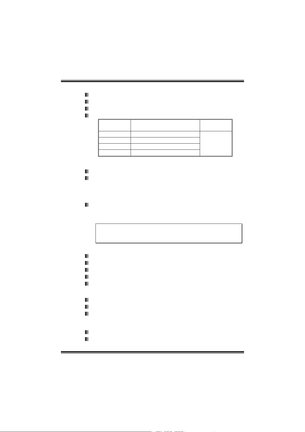
DIMM Socket
Location
DIMM1 128MB/256MB/512MB/1GB *1
DIMM2 128MB/256MB/512MB/1GB *1
DIMM3 128MB/256MB/512MB/1GB *1
DIMM4 128MB/256MB/512MB/1GB *1
DDR Module
Total Mem ory
Max is 4 GB.
Expansion Slots
Three 32bit PCI bus master slots.
Normal Mode PCI-Express slots:
- One PCI-Express x16 slot: PEX16-1.
- Three PCI-Express x1 slots: PEX16-2, PEX1-1 and
PEX1-2 slots
SLI Mode PCI-Express slots:
- Two PCI-Express x8 slots: PEX16-1 and PEX16-2.
- Two PCI-Express x1 slots. PEX1-1 and PEX1-2.
Notice:
Normal Mode and SLI Mode are switched by SLI-NF4 selector card.
(Please read Chapter 5 for detail information.)
Size (MB)
Gigabit Ethernet LAN
NVIDIA Gigabit MAC + VITESSE Gigabit PHY VSC8201.
Supports 10Mb/s, 100Mb/s and 1GB/s auto-negotiation.
Half/Full duplex capability.
Supports personal Firewall setup.
Supports ACPI power management.
On-board AC’97 Audio Sound Codec
Chip: ALC850:
Compliant with AC’97 versio n2.3 specification.
Supports 8 channels audio output.
IEEE 1394A Chip (optional)
Chip: VIA VT6307.
Supports 2 ports with transfer up to 400Mb/s.
2
Page 5

N4SLI-A9
Super I/O
Chip: ITE IT8712F.
Low Pin Count Interface.
Provides the most commonly used legacy Super I/O
functionality.
Environment Control initiatives,
- H/W Monitor
- Fan Speed Controller
- ITE's "Smart Guardian" function
Serial ATA
4 on-board Serial ATA connectors support 4 serial ATA (SATA)
ports.
Supports data transfer rates 1.5Gb/s or 3Gb/s.
Compliant with SATA2.0 specificatio n.
RAID Controller
Integrated in nForce4 CK8-04 SLI:
NVIDIA RAID Technology:
- RAID 0 disk striping for highest system and application
performance
- RAID 1 disk mirroring support for fault tolerance
Support for both SATA and ATA-133 disk controller
standards
- RAID 0+1 disk striping and mirroring for highest
performance with fault tolerance
Security
NVIDIA Network Management:
- Remote access, configuration, monitoring
- Command line interface (CLI)
- WMI scripts.
NVIDIA Firewall technology:
- Native firewall solution, protects the PC from intruders by
filtering unauthorized traffic.
Internal On-board Connectors and Headers
1 audio-out header supports audio-out facilities.
1 front panel header supports front panel facilities.
1 CD-in connector supports CD-ROM audio-in function.
1 SPDIF-out connector supports digital audio-out function.
1 IEEE1394A header supports 1 1394A Firewire port (optional).
3
Page 6
N4SLI-A9
N
1 SPDIF-in connector supports digital audio-in function
(optional).
1 floppy connector supports 2 FDD devices with 360K, 720K,
1.2M, 1.44M and 2.88Mbytes.
2 IDE connectors support 4 IDE disk drives.
3 USB headers support 6 USB 2.0 ports at front panel.
4 Serial ATA connectors support 4 SATA 2.0 devices.
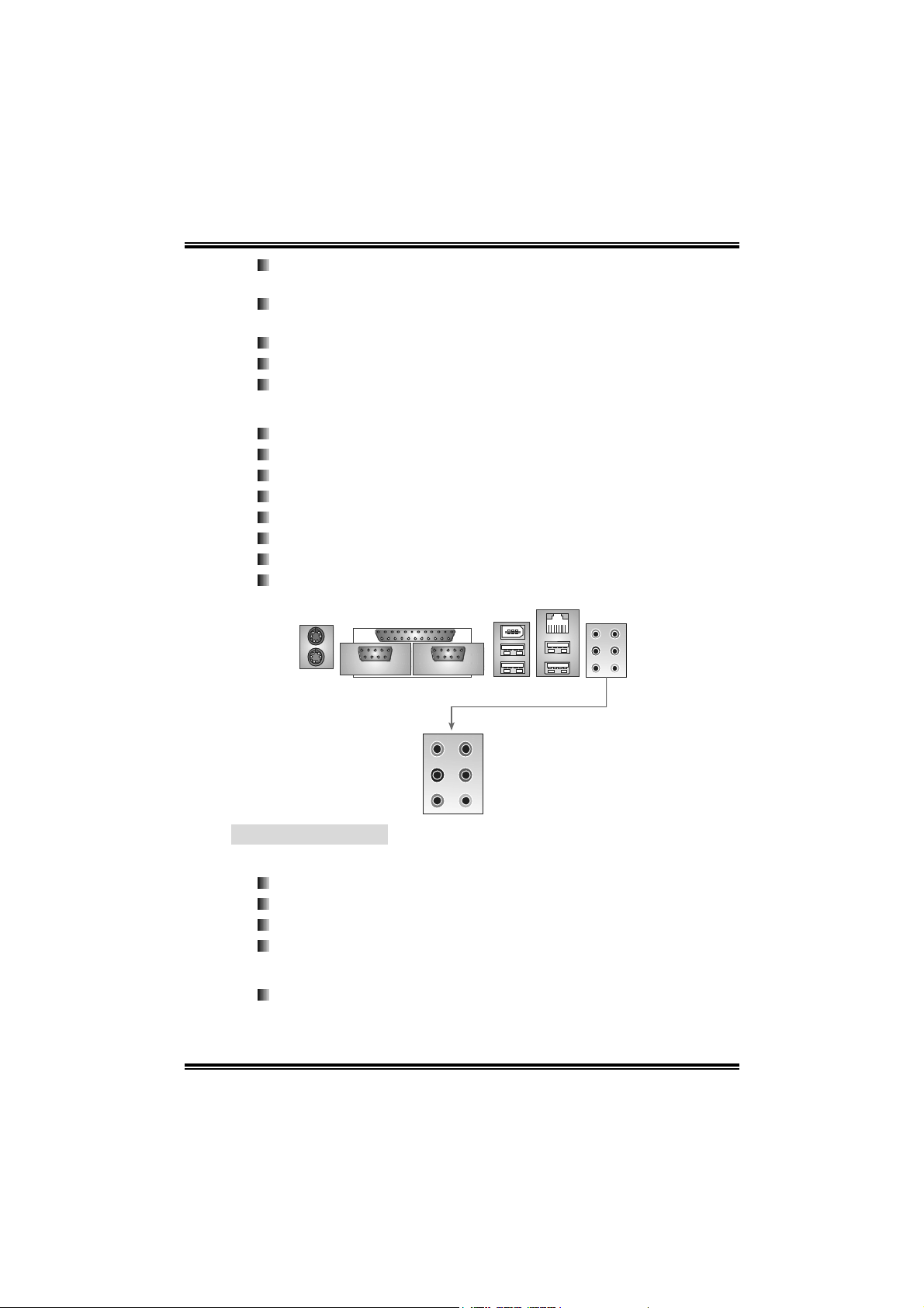
Rear (Back Panel) Side Connectors
1 Printer Port.
1 PS/2 Mouse Port.
1 PS/2 Keyboard Port.
1 Serial Port. (COM2 is optional.)
1 1394A Firewire Port (optional).
1 RJ-45 LAN jack.
4 USB 2.0 Ports.
6 audio ports support 8 channels audio-out facilities.
LA
Connector
PS/2
Mouse
Pri nter P ort
1394 Port
(opti onal)
PS/2
Keyboard
COM1
Center/Left
Rear
Si d e
COM2
(optional)
Line-in
Line-out
MIC-in
USB *2
USB *2
B. BIOS & Software
BIOS
Award legal BIOS.
Supports APM1.2.
Supports ACPI.
Supports USB Function.
Bundled Software
Supports 9th Touch™, WINFLASHER™ and FLASHER™.
4
Page 7

N4SLI-A9
1.2 PACKAGE CHECKLIST
FDD Cable x 1
HDD Cable x 1
User’s Manual x 1
Serial ATA Cable x 1
BRI-2 SLI Bridge x 1
Fully Setup Driver CD x 1
Rear I/O Panel for ATX Case x 1
SLI-NF4 Selector Card x 1 (pre-installed)
SPDIF Cable x 1 (optional)
USB 2.0 Cable x 1 (optional)
Retention Bracket x 1 (optional)
IEEE 1394A Cable x 1 (optional)
Serial ATA Power Switch Cable x 1 (optional)
5
Page 8

N4SLI-A9
1.3 LAY OUT & COMPONENTS
JKB MS1
JCOM 1
C
O
M
1
JPRNT1
C
O
M
2
JCOM2
(opti onal)
J1394_ US B1
JUS BLA N1
JATXPWR2
JKBMSV1
CP U1
J1394_USBV1
JCFAN1
JATXPWR1
Socket 939
DIMM2
DIMM1
DIMM4
DIMM3
IDE2
IDE1
EARPHONEJACK1
Giga LAN
JCDIN1
JAUDIO2
Cod ec
JP EXPW R1
PEX16-1
PE X1 - 1
PEX1-2
PEX16-2
PCI1
JSPDIF_OUT
Super I/O
JCI2
(opt io na l)
PCI2
PCI3
JSPDIF_IN1
(optional)
Note: ■ represents the 1st pin.
SLI 1
J1394PWR1
(opt i o nal )
IEEE 139 4
Chip
(optional)
BI OS
JUSB1
J1394A1
(optional)
nForce4
CK8-04
SLI
JU SB3
JU SB2
JUSBV1
JP AN E L 1
FDD1
JCMOS1
JNBFAN1
BAT1
JSATA1
JSATA2
JSATA3
JSATA4
JCI1
JSFAN1
(optional)
6
Page 9
N4SLI-A9
CHAPTER 2: HARDWARE INSTALLATION
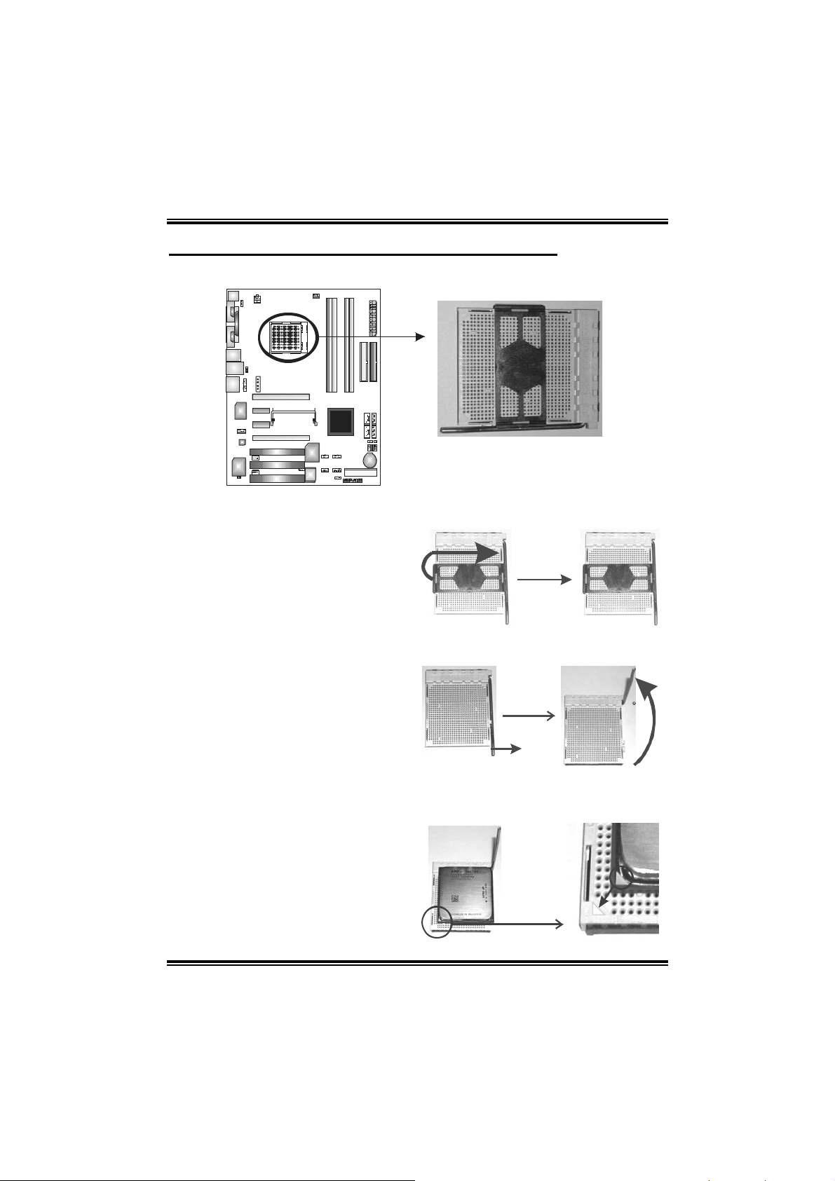
2.1 CENTRAL PROCESSING UNIT (CPU)
Step 1: Remove the socket protection cap.
Step 2: Pull the lever toward direction A from the socket and then raise
the lever up to a 90-degree angle.
90
A
Step 3: Look for the white triangle on socket, and the gold triangle on
CPU should point forwards this white triangle. The CPU will fit
only in the correct orientation.
7
Page 10

N4SLI-A9
Step 4: Hold the CPU down firmly, and then close the lever toward direct
B to complete the installation.
Step 5: Put the CPU Fan on the CPU and buckle it. Connect the CPU
FAN power cable to the JCFAN1. This completes the installation.
2.2 FAN HEADERS
JCFAN1: CPU FAN Power Header
JSFAN1: System Fan Power Header (optional)
JNBFAN1: Northbridge Fan Power Header
JCFAN1
13
JNBFAN1 JSFAN1
31
1
3
Note:
The JCFAN1 and JSFAN1 support system cooling fan with Smart Fan Control
utility. It supports 3 pin head connector. When connecting with wires onto
connectors, please note that the red wire is the positive and should be connected
to pin#2, and the black wire is Ground and should be connected to GND.
Assignment
Pin
1 Ground
2 +12V
3 FAN RPM rate sense
(Only for JCFAN1 and
JSFA N1. )
B
8
Page 11
N4SLI-A9
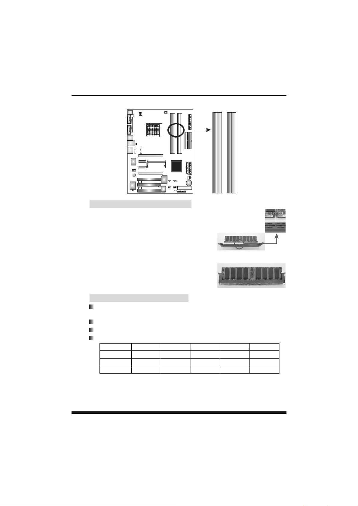
2.3 MEMORY MODULES INSTALLATION
2.2.1 DDR Module installation
1. Unlock a DIMM slot by pressing the
retaining clips outward. Align a DIMM on
the slot such that the notch on the DIMM
matches the break on the Slot.
2. Insert the DIMM vertically and firmly into
the slot until the retaining chip snap back
in place and the DIMM is properly seated.
DIMM1
DIMM2
DIMM4
DIMM3
2.2.2 DDR Installation Notice
Please follow the table below to install your DDR memory module, or
the system may not boot up or may not function properly.
“SS” represents Single Sid e DDR memory module.
“DS” represents Double Side DDR memory module.
Star sign “*” represents leave the DIMM socket empty.
DIMM1 SS/DS * SS/DS * SS/DS
DIMM2 * * SS/DS * SS/DS
DIMM3 * SS/DS * SS/DS SS/DS
DIMM4 * * * SS/DS SS/DS
9
Page 12

N4SLI-A9
2.4 CONNECTORS & SLOTS
FDD1: Floppy Disk Connector
The motherboard provides a standard floppy disk connector that
supports 360K, 720K, 1.2M, 1.44M and 2.88M floppy disk types.
This connector supports the provided floppy drive ribbon cables.
2
1
34
33
IDE1/IDE2: Hard Disk Connectors
The motherboard has two 32-bit Enhanced PCI IDE Controller that
provides PIO Mode 0~5, Bus Master, and Ultra DMA 33/66/100/133
functionality. It has two HDD connectors IDE1 (primary) and IDE2
(secondary). The IDE connectors can connect a master and a slave
drive, so you can connect up to four hard disk drives. The first hard
drive should always be connected to IDE1.
IDE2 IDE1
3940
12
10
Page 13

N4SLI-A9
PCI1~PCI3: Peripheral Component Interconnect Slots
This motherboard is equipped with 3 standard PCI slot. PCI stands
for Peripheral Component Interconnect, and it is a bus standard for
expansion cards. This PCI slot is designated as 32 bits.
PCI1
PCI2
PCI3
PEX16-1/PEX16-2/PEX1-1/PEX1-2:PCI-Express Slots
PEX16-1 (Normal Mode):
- PCI Express 1.0a compliant.
- Maximum bandwidth is up to 4GB/s per direction.
PEX16-1/PEX1-1/PEX1-2 (Normal Mode):
- PCI Express 1.0a compliant.
- Maximum bandwidth is up to 250MB/s per direction.
PEX16-1/PEX16-2 (SLI Mode):
- PCI Express 1.0a compliant.
- Maximum bandwidth is up to 2GB/s per direction.
11
PEX16-1
PEX1-1
PEX1-2
PEX16-2
Page 14
N4SLI-A9
CHAPTER 3: HEADERS & JUMPERS SETUP
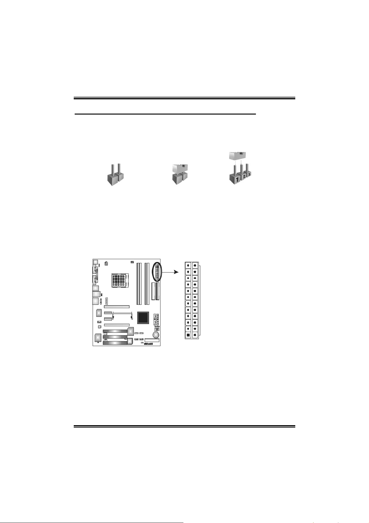
3.1 HOW TO SETUP JUMPERS
The illustration shows how to set up jumpers. When the jumper cap is
placed on pins, the jumper is “close”, if not, that means the jumper is
“open”.
Pin opened Pin closed Pin1-2 closed
3.2 DETAIL SETTINGS
JATXPWR1/JATXPWR2: ATX Powe r Source Connectors
This connector allows user to connect 24-pin power connector on the ATX
power supply.
Pin Assignment
1 +3.3V
2 +3.3V
3 Ground
4 +5V
12 24
1
13
5 Ground
6 +5V
7 Ground
8 PW_OK
9 Standby Voltage+5V
10 +12V
11 +12V
12 Detect
13 +3.3V
14 -12V
15 Ground
16 PS_ON
17 Ground
18 Ground
19 Ground
20 -5V
21 +5V
22 +5V
23 +5V
24 Ground
12
Page 15
N4SLI-A9
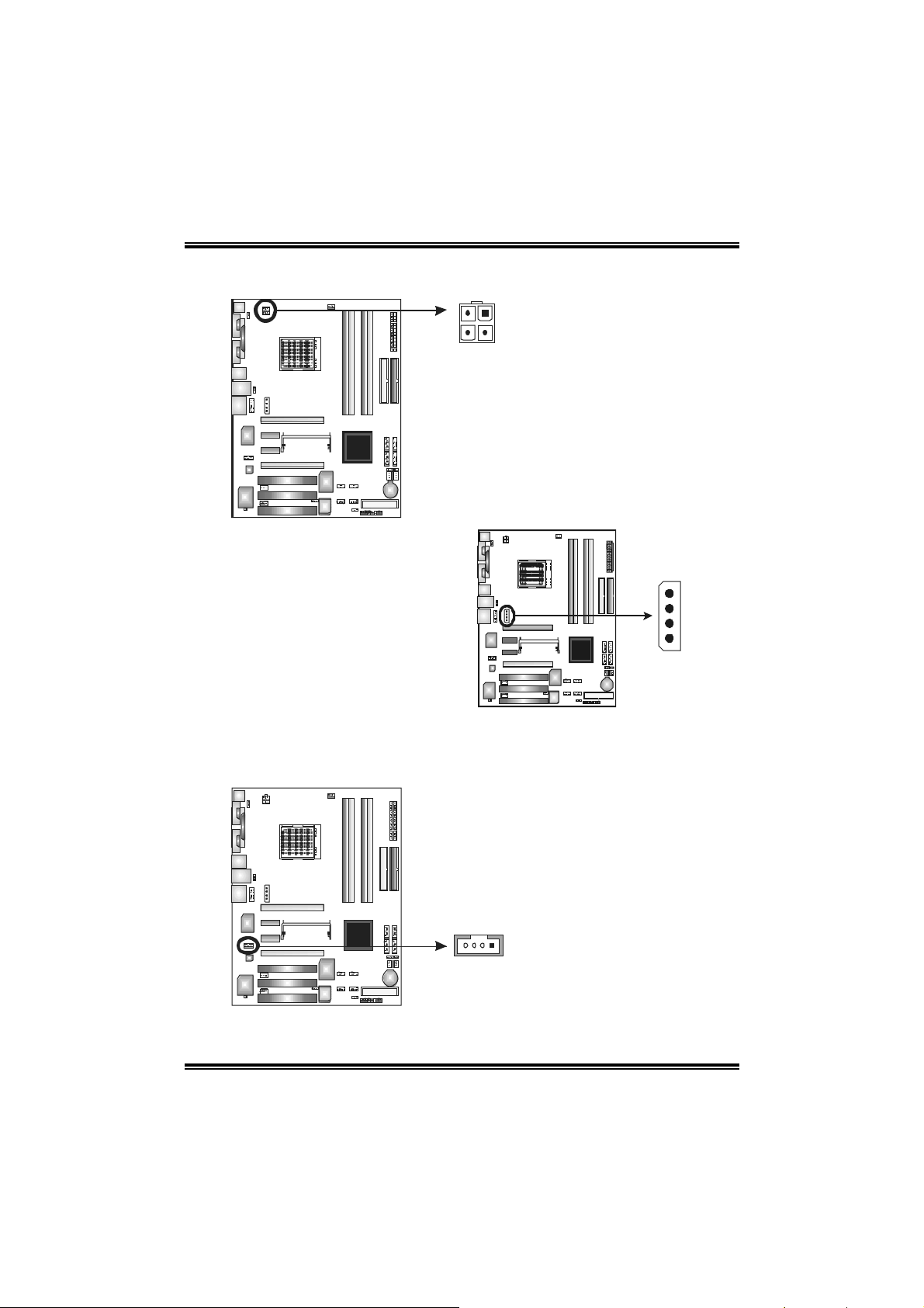
JATXPWR2: ATX Powe r Source Co nnector
By connecting this connector, it will provide +12V to CPU power circuit.
1
2
4
3
JPEXPWR1:
PCI-Express x16 Slot Power
Source Connector
When SLI mode is enabled,
please plug in this PEX power
source connector to make sure
the system is working under a
stable environment. Please read
Chapter 5 for detail information.
JCDIN1: CD-ROM Audio-in Connector
This connector allows user to connect the audio source from the variety
devices, like CD-ROM, DVD-ROM, PCI sound card, PCI TV turner card etc..
Assignment
Pin
1 +12V
2 +12V
3 Ground
4 Ground
Assignment
Pin
1 Left channel input
2 Ground
3 Ground
4 Right channel input
+12V
Ground
Ground
VCC
13
14
Page 16
N4SLI-A9
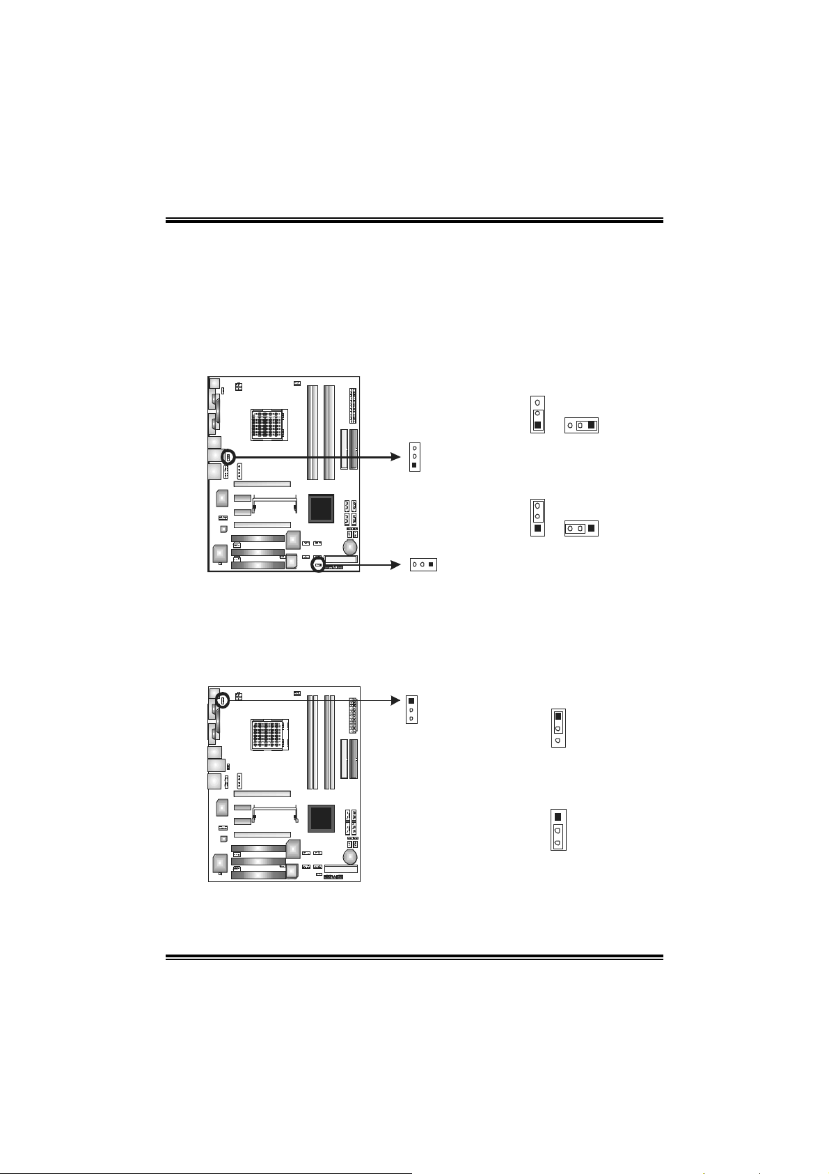
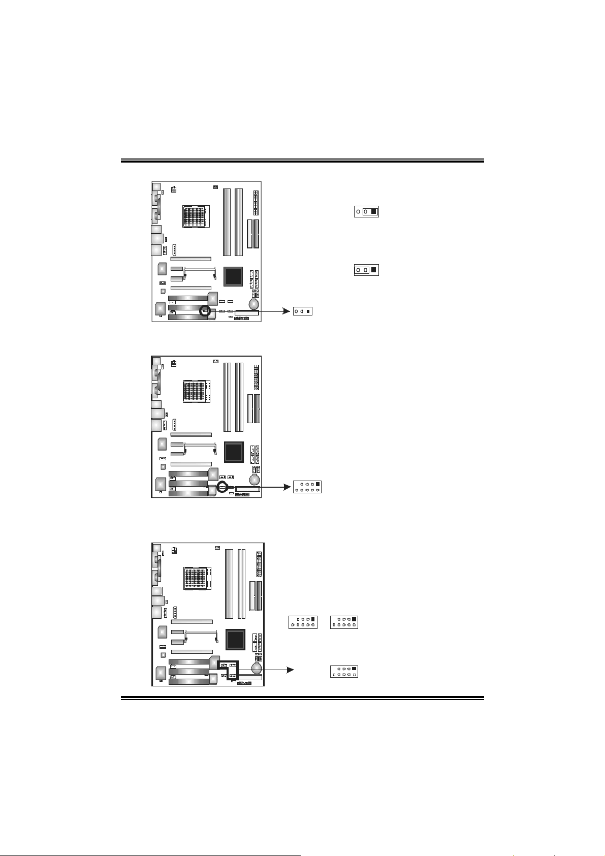
J1394_USBV1/JUSBV1: Power Source Headers for USB Ports
Pin 1-2 Close:
J1394_USBV1: +5V for USB ports at J1394_USB1 and JUSBLAN1.
JUSBV1: +5V for front USB headers (JUSB1/JUSB2/JUSB3).
Pin 2-3 Close:
J1394_USBV1: USB ports at J1394_USB1 and JUSBLAN1 are powered with
+5V standby voltage.
JUSBV1: Front USB headers (JUSB1/JUSB2/JUSB3) are powered with +5V
standby voltage.
J1394_USBV1
3
1
JUSBV 1
13
3
1
Pin 1-2 Close
3
1
Pin 2-3 Close
13
13
Note: In order to support this function “Power-on s ystem via USB device,”
“J1394_USBV1/JUSBV1” jumper cap should be placed on Pin 2-3 individually.
JKBMSV1: Power Source Header for PS/2 Keyboard/ Mouse
Pin 1-2 Close: +5V for PS/2 keyboard and mouse..
Pin 2-3 Close: PS/2 keyboard and mouse are powered with +5V standby
voltage.
1
3
1
3
Pin 1-2 close
1
3
Pin 2-3 close
Note: In order to support this function “Power-on s ystem via keyboard and mouse”,
“JKBMSV1” jumper cap should be placed on Pin 2-3.
14
Page 17
N4SLI-A9
JSPDIF_OUT/JSPDIF_IN1: Digital Audio-out Connectors
(JSPDIF_IN1 is optional.)
These connectors allow user to connect the PCI bracket SPDIF output or input
header.
JS PDIF_O UT:
JSPDIF_OUT
1313
JSPDIF_IN1
13
JAUDIO2: Front Panel Audio-out Header
This connector will allow user to connect with the front audio out put headers on
the PC case. It will disable the output on back panel audio connectors.
1
2
13
14
Pin Assignment
1 +5V
2 SPD IF OUT
3 Ground
JS PDIF_I N1:
Pin Assignment
1 +5V
2 SPD IF IN
3 Ground
Pin Assignment
1 MIC-in/
Stereo MIC-in R
2 Ground
3 Stereo MIC-in L
4 Audio power
5 Right line-out/
Speaker-out Right.
6 Right line-out/
Speaker-out Right
7 Reserved
8 Key
9 Left line-out/ Speaker-out
Left
10 Left line-out/ Speaker-out
Left
11 Right line-in (optional)
12 Right line-in (optional)
13 Left line-in (optional)
14 Left line-in (optional)
15
Page 18
N4SLI-A9
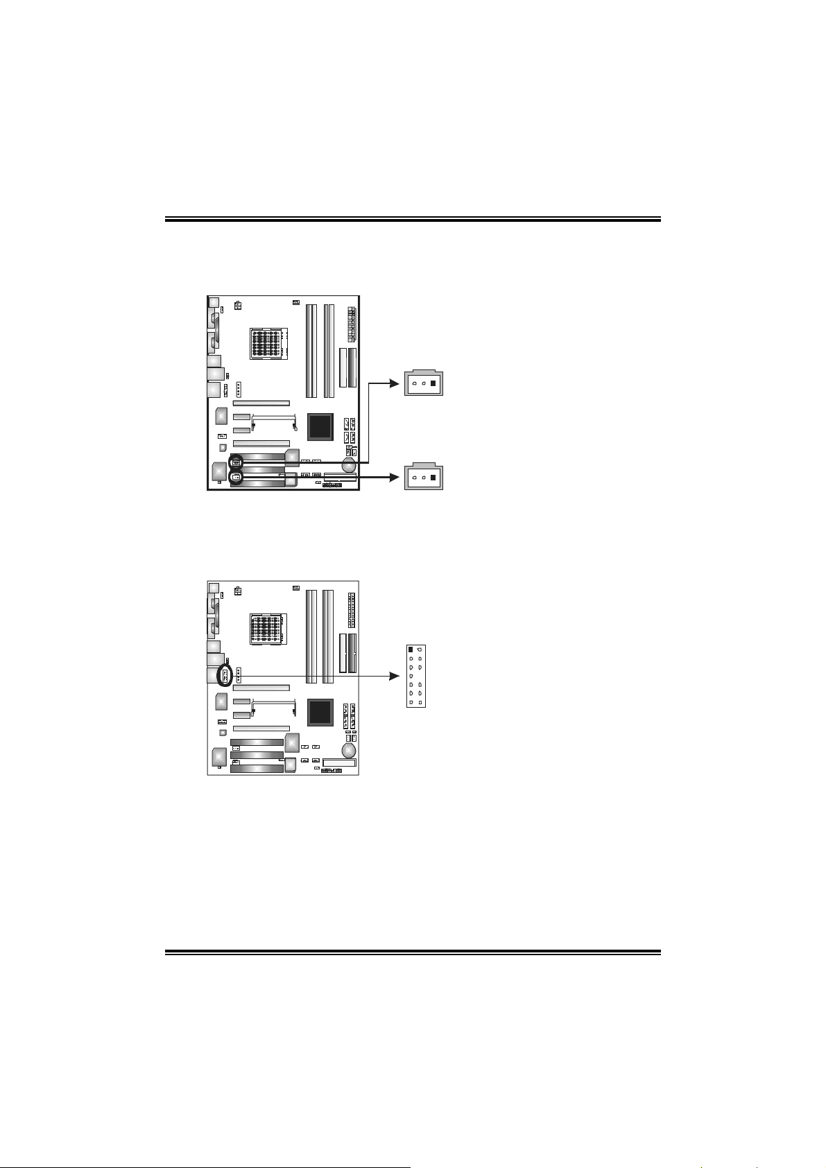
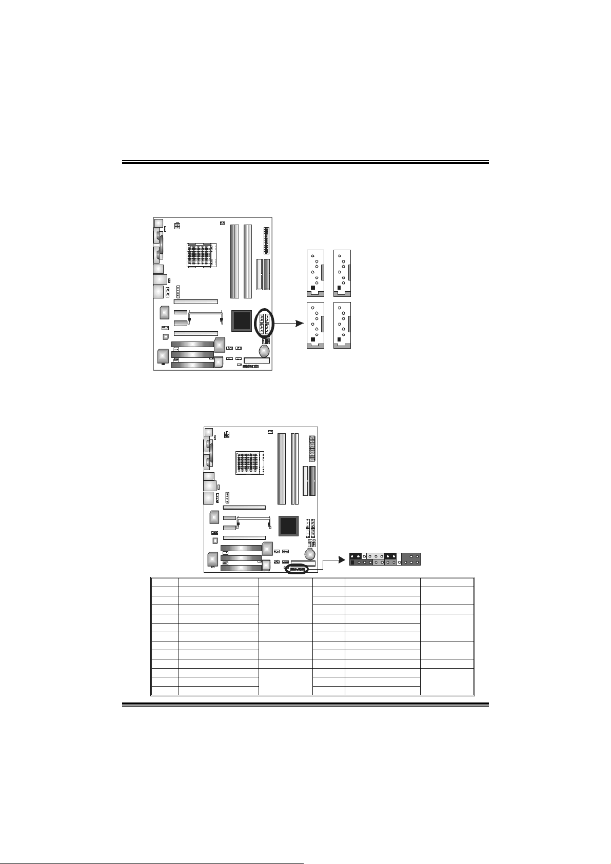
J1394PWR1 (optional): Power Source Header for 1394 Chip
13
Pin 1-2 Close:
+3.3V for 1394 chipset (default).
13
Pin 2-3 Close:
+3.3V SB for 1394 chipset.
13
J1394A1 (optional): Header for 1394A Firewire Port at Front Panel
This header allows user to connect the front 1394 port for digital image devices.
19
Pin
Assignment
1 A+
2 A3 Ground
4 Ground
5 B+
6 B7 +12v
8 +12V
9 Key
10 Ground
10 2
JUSB1~JUSB3: Headers for USB Ports at Front Panel
This connector allows user to connect additional USB cables at PC front panel,
and also can be connected with internal USB devices, like USB card reader.
JUSB3
19
2
JUSB1
16
10
JUSB2
Assignment
Pin
1 +5V (fused)
2 +5V (fused)
3 USB4 USB5 USB+
6 USB+
7 Ground
8 Ground
9 Key
10 NC
Page 19

N4SLI-A9
JCMOS1: Clear CMOS Header
By placing the jumper on pin2-3, it allows user to restore the BIOS safe setting
and the CMOS data, please carefully follow the procedures to avoid damaging
the motherboard.
13
Pin 1-2 close:
Normal Operation (Default).
13
13
Clear CMOS Proced※ ures:
1. Remove AC power line.
2. Set the jumper to “Pin 2-3 close”.
3. Wait for five seconds.
4. Set the jumper to “Pin 1-2 close”.
5. Power on the AC.
6. Reset your desired password or clear the CMOS data.
JCI1/JCI2: Case Open Headers (JCI2 is optional.)
This connector allows system to monitor PC case open status. If the signal has
been triggered, it will record to the CMOS and show the message on next
boot-up.
Pin 2-3 close:
Clear CMOS data.
Assignment
Pin
1 Case open signal
2 Ground
12
12
17
JCI1
JCI2
(o pti ona l)
Page 20
N4SLI-A9
JSATA1 ~JSATA4: Se rial ATA Connectors
The motherboard has a SATA Controller in nForce4 CK8-04 SLI with 4
channels SATA interface, it satisfies the SATA 2.0 spec and with transfer rate of
3.0Gb/s.
J SAT A17J SAT A2
4
1
7
4
1
J SAT A4J SAT A3
JPANEL1: Header for Front Panel Facilities
This 24-pin connector includes Power-on, Reset, HDD LED, Power LED, Sleep
button, speaker and IrDA Connection. It allows user to connect the PC case’s
front panel switch functions.
Assignment
Pin
1 Ground
2 TX+
3 TX4 Ground
5 RX6 RX+
7 Ground
224
123
Pin Assignment Function Pin Assignment Function
1 +5V 2 Sleep control
3 N/A 4 Ground
5 N/ A 6 N/ A N/A
7 Speaker
9 HDD LED (+) 10 Power LED (+)
11 HDD LED (-)
13 Ground 14 Power button
15 Reset control
17 N/A 18 Key
19 N/A 20 Key
21 +5V 22 Ground
23 IRTX
Speaker
Connector
Hard drive LED
Reset button
IrDA Connector
8 Power LED (+)
12 Power LED (-)
16 Ground
24 IRRX
Sleep button
Power LED
Power-on
button
IrDA Connector
18
Page 21
N4SLI-A9
CHAPTER 4: USEFUL HELP
4.1 AWARD BIOS BEEP CODE
Beep Sound Meaning
One long beep followed by two short
beeps
High-low siren sound CPU overheated
One Short beep when system boot-up No error found during POST
Long beeps every other second No DRAM detected or install
4.2 EXTRA INFORMATION
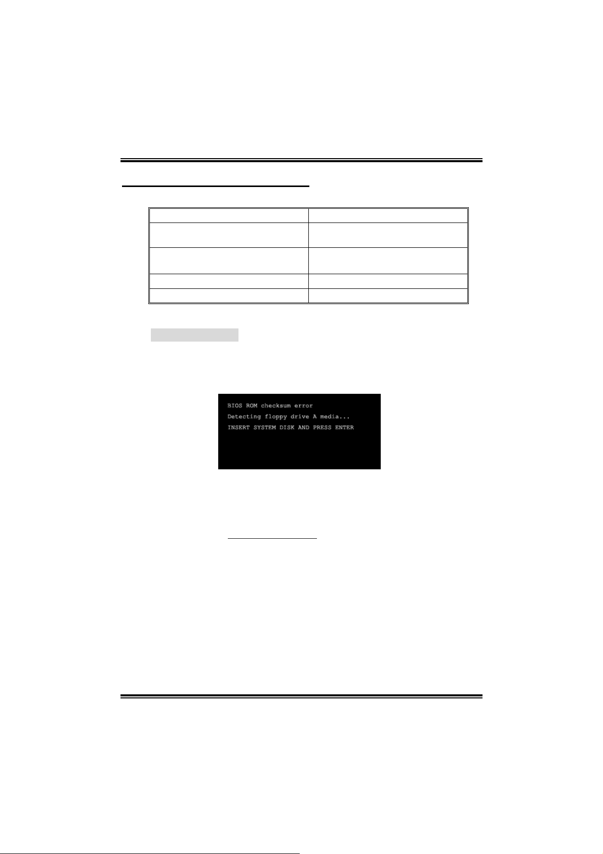
A. BIOS Update
After you fail to update BIOS or BIOS is invaded by virus, the
Boot-Block function will help to restore BIOS. If the following
message is shown after boot-up the system, it means the BIOS
contents are corrupted.
Video card not found or video card
memory bad
System will shut down automatically
In this Case, please follow the procedure below to restore the BIOS:
1. Make a bootable floppy disk.
2. Download the Flash Utility “AWDFLASH.exe” from the Biostar
website: www.biostar.com.tw
3. Confirm motherboard model and download the respectively
BIOS from Biostar website.
4. Copy “AWDFLASH.exe” and respectively BIOS into floppy disk.
5. Insert the bootable disk into floppy drive and press Enter.
6. System will boo-up to DOS prompt.
7. Type “Awdflash xxxx.bf/sn/py/r” in DOS prompt.
8. System will update BIOS automatically and restart.
9. The BIOS has bee n recovered and will work properly.
19
Page 22

N4SLI-A9
B. CPU Overheated
If the system shutdown automatically after power on system for
seconds, that means the CPU protection function has been activated.
When the CPU is over heated, the motherboard will shutdow n
automatically to avoid a damage of the CPU, and the system may not
power on again.
In this case, please double check:
1. The CPU cooler surface is placed evenly with the CPU surface.
2. CPU fan is rotated normally.
3. CPU fan speed is fulfilling with the CPU speed.
After confirmed, please follow steps below to relief the CPU
protection function.
1. Remove the power cord from power supply for seconds.
2. Wait for seconds.
3. Plug in the power cord and boot up the system.
Or you can:
1. Clear the CMOS data.
(See “JCMOS1: Clear CMOS Header” section)
2. Wait for seconds.
3. Power on the system again.
20
Page 23

4.3 TROUBLESHOOTING
Probable Solution
1. No power to the system at all
Power light don’t illuminate, fan
inside power supply does not
turn on.
2. Indicator light on keyboard does
not turn on.
System inoperative. Keyboard lights
are on, power indicator lights are lit,
and hard drive is spinning.
System does not boot from hard disk
drive, can be booted from optical drive.
System only boots from optical drive.
Hard disk can be read and applications
can be used but booting from hard disk
is impossible.
Screen message says “Invalid
Configuration” or “CMOS Failure.”
Cannot boot system after installing
second hard drive.
N4SLI-A9
1. Make sure power cable is securely
plugged in.
2. Replace cable.
3. Contact technical support.
Using even pressure on both ends of the
DIMM, press down firmly until the module
snaps into place.
1. Check cable running from disk to
disk controller board. Make sure
both ends are securely plugged in;
check the drive type in the
standard CMOS setup.
2. Backing up the hard drive is
extremely important. All hard disks
are capable of breaking down at
any time.
1. Back up data and applications
files.
2. Reformat the hard drive. Re-install
applications and data using
backup disks.
Review system’s equipment. Make sure
correct information is in setup.
1. Set master/slave jumpers
correctly.
2. Run SET UP program and select
correct drive types. Call the drive
manufacturers for compatibility
with other drives.
21
Page 24

N4SLI-A9
CHAPTER 5: NVIDIA SLI FUNCTION
5.1 REQUIREMENTS
Only Windows XP supports SLI (Dual Video) function.
Two identical SLI-ready graphics cards that are NVIDIA certified.
The graphics card driver should support NVIDIA SLI technology.
The power supply unit must provide at least the minimum power
required by the system, or the system will be unstable.
5.2 PLACING THE SLI-NF4 SELECTOR CARD
There is a pre-installed SLI-NF4 selector card on the motherboard.
The default setting is Normal Mode, only supports single graphics
card.
To use two graphics cards, firstly, you have to set the selector card to
SLI Mode, to support dual video cards.
Step 1: Push the retention clips outward to release SLI-NF4
selector card.
Step 2: Pull the selector card out of the slot.
22
2 pull out the
○
selector card
1 about 45
○
degree li ft.
O
Page 25

N4SLI-A9
Step 3: Invert the selector card and insert the edge labeled “SLI
MODE”.
Step 4: Push down the selector card until the retention clips snap
into place.
1 Insert the ca rd with a
○
degree about 450.
2 Push the selector
○
Notice: Make sure to insert the card into the slot completely.
23
card downward.
Page 26

N4SLI-A9
5.3 THINGS TO NOTICE
Normal Mode:
- Only PEX16-1 slot supports PCI-Express x16 interface graphics
card function.
- PEX16-2, PEX1-1 and PEX1-2 slots provide PCI-Express x1
interface expansion card function.
SLI Mode:
- Use BRI-SLI connector to link two SLI-ready PCI-E x16 interface
graphics cards.
- PEX16-1 and PEX16-2 slots provide PCI-E x8 data transfer rate.
- PEX1-1 and PEX1-2 slots provide PCI-Express x1 interface
expansion card function.
- Coordinate with graphics card driver to set Dual Video function.
5.4 INSTALLING SLI-READY GRAPHICS CARDS
Step 1: Make sure the SLI-NF4 selector card is placed at SLI Mode.
Step 2: Prepare two graphics cards with PCI-E x16 interface.
Step 3: Insert the first one graphics card into the yellow slot
(PEX16-1).
Step 4: Insert the second graphics card into the white slot (PEX16-2).
PEX16-1
PEX16-2
Notice:
Make sure both the graphics cards are seated into slots completely.
24
Page 27

N4SLI-A9
Step 5: Connect a 4-pin ATX power cable to PEX power connector
(JPEXPWR1), this will ensure t he stabilization of your system.
Notice:
When under SLI mode, please make sure the
power supply is at least 500W (and above).
Step 6: Insert the SLI Bridge (BRI-2) connector on the gold-fingers on
each graphics card.
Front view Side view
Gold-fingers on
two graphics
Step 7: To securely fix the connector between two graphics cards, a
retention bracket must be installed.
Step 7-1: Remove any of the bracket cover between the two
graphics cards.
Step 7-2: Align and insert the retention bracket into the slot
and then fix it with a screw.
Notice:
1. Make sure the retention bracket supports the SLI Bridge
(BRI-2) firmly.
2. Retention bracket is optional
25
Page 28

N4SLI-A9
5.5 ENABLING MULTI-GPU FEATURE IN WINDOWS
After the graphics cards are installed, enable the Multi-GPU feature in
NVIDIA nView properties.
Step 1:
Click NVIDIA Settings icon on the
Windows taskbar.
Step 2:
Select nView Properties in nView
Desktop Manager pop-up menu.
Step 3:
Click Properties icon in Desktop
Management tab to display Display
Properties dialog box.
Step 4:
Click Advanced icon in Settings tab.
26
Page 29

N4SLI-A9
Step 5:
Select NVIDIA GeForce tab, and then
click o n Multi-GPU item on the left dialog
box.
Step 6:
Check before Enable SLI
multi-GPU item, and click on OK
to complete the setting.
27
Page 30

N4SLI-A9
CHAPTER 6: NVIDIA RAID FUNCTIONS
6.1 OPERATION SYSTEM
Supports Windows XP Home/Professional Edition, and Windows
2000 Professional.
6.2 RAID ARRAYS
NVRAID supports the following types of RAID arrays:
RAID 0: RAID 0 defines a disk striping scheme that improves disk read and
writes times for many applications.
RAID 1: RAID 1 defines techniques for mirroring data.
RAID 0+1: RAID 0+1 combines the techniques used in RAID 0 and RAID 1.
Spanning (JBOD): JBOD provides a method for combining drives of different
sizes in to one large disk.
6.3 HOW RAID WORKS
RAID 0:
The controller “stripes” data across
multiple drives in a RAID 0 array
system. It breaks up a large file into
smaller blocks and performs disk
reads and writes across multiple
drives in parallel. The size of each
block is determined by the strip size
parameter, which you set d ur i ng t he
creation of the RAID set based on the
system environment. This technique
reduces overall disk access time and
offers high bandwidth.
Blo ck 1
Block 3
Block 5
Blo ck 2
Blo ck 4
Blo ck 6
Features and Benefits
- Drives: Minimum 1, and maximum is up to 6 or 8. Depending on the
platform.
- Uses: Intended for non-critical data requiring high data throughput, or
any environment that does not require fault tolerance.
- Benefits: provides increased data throughput, especially for large files.
No capacity loss penalty for parity.
- Drawbacks: Does not deliver any fault tolerance. If any drive in the
array fails, all data is lost.
- Fault Tolerance: No.
28
Page 31

N4SLI-A9
RAID 1:
Every read and write is actually carried out in parallel across 2 disk drives in a
RAID 1 array system. The mirrored (backup) copy of the data can reside on
the same disk or on a second
redundant drive in the array. RAID
1 provides a hot-standby copy of
data if the active volume or drive is
corrupted or becomes unavailable
because of a hardware failure.
RAID techniques can be applied
for high-availability solutions, or as
a for m of a utomatic backup that
eliminates tedious manual backups
to more expensive and less reliable
media.
Features and Benefits
- Drives: Minimum 2, and maximum is 2.
- Uses: RAID 1 is ideal for small databases or any other application that
requires fault tolerance and minimal capacity.
- Benefits: Provides 100% data redundancy. Should one drive fail, the
controller switches to the other drive.
- Drawbacks: Requires 2 drives for the storage space of one drive.
Performance is impaired during drive rebuilds.
- Fault Tolerance: Yes.
Blo ck 1
Block 2
Block 3
Blo ck 1
Block 2
Block 3
RAID 0+1:
RAID 0 drives can be mirrored
suing RAID 1 techniques.
Resulting in a RAID 0+1
solution for improved
performance plus resiliency.
Block 1
Block 3
Block 5
Features and Benefits
- Drives: Minimum 4, and maximum is 6 or 8, depending on the platform.
- Benefits: Optimizes for both fault tolerance and performance, allowing
for automatic redundancy. May be simultaneously used with other RAID
levels in an array, and allows for spare disks.
- Drawbacks: Requires twice the available disk space for data redundancy,
the same as RAID level 1.
- Fault Tolerance: Yes.
29
Block 2
Block 4
Block 6
Block 1
Block 3
Block 5
Block 2
Block 4
Block 6
Page 32

N4SLI-A9
Spanning (JBOD):
JBOD stands for “Just a Bunch of Disks”. Each drive is accessed as if it were
on a standard SCSI host bus
adapter. This is useful when a
single drive configuration is needed,
but it offers no speed improvement
or fault tolerance.
Features and Benefits
- Uses: JBOD works best if you have odd sized drives and you want to
combine them to make one big drive.
- Benefits: JBOD provides the ability to combine odd size drives using all
of the capacity of the drives.
- Drawbacks: Decreases performance because of the difficulty in using
drives concurrently.
- Fault Tolerance: Yes.
※ For more detailed setup information, please refer to the Driver CD, or
http://www.nvidia.com/page/pg_20011106217193.html to download
go to
NVIDIA nForce Tutorial Flash.
Single Logical
Drive
Disk 1: 40GB
Disk 2: 80GB
Disk 3: 40GB
Disk 4: 120GB
30
Page 33

N4SLI-A9
CHAPTER 7: WARPSPEEDER™
7.1 INTRODU CTION
[WarpSpeeder™], a new powerful control utility, features three
user-friendly functions including Overclock Manager, Overvoltage
Manager, and Hardware Monitor.
With the Overclock Manager, users can easily adjust the frequency they
prefer or they can get the best CPU performance with just one click. The
Overvoltage Manager, on the other hand, helps to power up CPU core
voltage and Memory voltage. The cool Hardware Monitor smartly
indicates the temperatures, voltage and CPU fan speed as well as the
chipset information. Also, in the About panel, you can get detail
descriptions about BIOS model and chipsets. In addition, the frequency
status of CPU, memory, AGP and PCI along with the CPU speed are
synchronically shown on our main panel.
Moreover, to protect users' computer systems if the setting is not
appropriate when testing and results in system fail or hang,
[WarpSpeeder™] technology assures the system stability by
automatically rebooting the computer and then restart to a speed that is
either the original system speed or a suitable one.
7.2 SYSTEM REQUIREMENT
OS Support: Windows 98 SE, Windows Me, Windows 2000, Windows XP
DirectX: DirectX 8.1 or above. (The Windows XP operating system
includes DirectX 8.1. If you use Windows XP, you do not need to install
DirectX 8.1.)
31
Page 34

N4SLI-A9
7.3 INSTALLATION
1. Execute t he setup execution file, and then the following dialog will
pop up. Please click “Next” button and follow the default procedure to
install.
2. When you see the following dialog in setup procedure, it means
setup is completed. If the “Launch the WarpSpeeder Tray Utility”
checkbox is checked, the Tray Icon utility and [WarpSpeeder™] utility
will be automatically and immed iately launched after you click
“Finis h” butto n.
Usage:
The following figures are just only for reference, the screen printed in
this user manual will change according to your motherboard on hand.
32
Page 35

N4SLI-A9
7.4 [WARPSPEEDER™] INCLUDES 1 TRAY ICON AND 5 PANELS
1. Tray Icon:
Whenever the Tray Icon utility is la unched, it will display a little tray
icon on the right side of Windows Taskbar.
This utility is responsible for conveniently invoking [WarpSpeeder™]
Utility. You can use the mouse by clicking the left button in order to
invoke [WarpSpeeder™] directly from the little tray icon or you can
right-click the little tray icon to pop up a popup menu as following
figure. The “Launch Utility” item in the popup menu has the same
function as mouse left-click o n tray icon and “Exit” item will close
Tray Icon utility if selected.
33
Page 36

N4SLI-A9
2. Main Panel
If you click the tray icon, [WarpSpeeder™] utility will be invoked.
Please refer to the following figure; the utility’s first window you will
see is Main Panel.
Main Panel contains features as follows:
a. Display the CPU Speed, CPU external clock, Memory clock,
AGP clock, and PCI clock information.
b. Contains About, Voltage, Overclock, and Hardware Monitor
Buttons for invoking respective panels.
c. With a user-friendly Status Animation, it can represent 3
overclock percentage stages:
Man walking→overclock percentage from 100% ~ 110 %
Panther running→overclock percentage from 110% ~ 120%
Car racing→overclock percentage from 120% ~ above
34
Page 37

N4SLI-A9
3. Voltage Panel
Click the Voltage button in Main Panel, the button will be
highlighted and the Voltage Panel will slide out to up as the
following figure.
In this panel, you can decide to increase CPU core voltage and
Memory voltage or not. The default setting is “No”. If you want to
get the best performance of overclocking, we recommend you click
the option “Yes”.
35
Page 38

N4SLI-A9
4. Overclock Panel
Click t he Overclock button in Main Panel, the button will be
highlighted and the Overclock Panel will slide out to left as the
following figure.
Overclock Panel contains the these features:
a. “–3MHz button”, “-1MHz button”, “+1MHz button”, and “+3MHz
button”: provide user the ability to do real-time overclock
adjustment.
Warning:
Manually overclock is potentially dangerous, especially when the
overclocking percentage is over 110 %. We strongly recommend you
verify every speed you overclock by click the Verify button. Or, you
can just click Auto overclock button and let [WarpSpeeder™]
automatically gets the best result for you.
b. “Recovery Dialog button”: Pop up the following dialog. Let user
select a restoring way if system need to do a fail-safe reboot.
36
Page 39

N4SLI-A9
c. “Auto-overclock button”: User can click this button and
[WarpSpeeder™] will set the best and stable performance and
frequency automatically. [WarpSpeeder™] utility will execute a
series of testing until system fail. Then system will do fail-safe
reboot by using Watchdog function. After reboot, the
[WarpSpeeder™] utility will restore to the hardware default
setting or load the verified best and stable frequency according
to the Recovery Dialog’s setting.
d. “Verify button”: User can click this button and [WarpSpeeder™]
will proceed a testing for current frequency. If the testing is ok,
then the current frequency will be saved into system registry. If
the testing fail, system will do a fail-safe rebooting. After reboot,
the [WarpSpeeder™] utility will restore to the hardware default
setting or load the verified best and stable frequency according
to the Recovery Dialog’s setting.
Note:
Because the testing programs, invoked in Auto-overclock and Verify,
include DirectDraw, Direct3D and DirectShow tests, the DirectX 8.1 or
newer runtime library is required. And please make sure your display
card’s color depth is High color (16 bit) or True color( 24/32 bit ) that is
required for Direct3D rendering.
5. Hardware Monitor Panel
Click the Hardware Monitor button in Main Panel, the button will be
highlighted a nd the Hardware Monitor panel will slide o ut to left as
the following figure.
In this panel, you can get the real-time status information of your
system. The information will be refreshed e very 1 second.
37
Page 40

N4SLI-A9
6. About Panel
Click the “about” button in Main Panel, the button will be highlig hted
and the About Pa nel will slide out to up as the following figure.
In this panel, you can get model name and detail information in
hints of all the chipset that are related to overclocking. You can also
get the mainboard’s BIOS model and the Version number of
[WarpSpeeder™] utility.
38
Page 41

N4SLI-A9
Note:
Because the overclock, overvoltage, and hardware monitor features
are controlled by several separate chipset, [WarpSpeeder™] divide
these features to separate panels. If one chipset is not on board, the
correlative button in Main panel will be disabled, but will not interfere
other panels’ functions. This property can make [WarpSpeeder™]
utility more robust.
04/25, 2005
39
Page 42

N4SLI-A9 BIOS Setup
BIOS Setup........................................................................................1
1 Main Menu.......................................................................................................3
2 Standard CMOS Features................................................................................... 6
3 Advanced BIOS Features ................................................................................... 9
4 Advanced Chipset Features............................................................................... 12
5 Integrated Peripherals ...................................................................................... 15
6 Power Management Setup................................................................................ 20
7 PnP/PCI Configurations................................................................................... 23
8 PC Health Status............................................................................................. 26
9 Voltage Control ............................................................................................... 28
i
Page 43

N4SLI-A9
BIOS Setup
Intro duction
T his manual discu ssed Award™ Setup program built into t he ROM BIOS. The Setup
program allows users to modify the basic system configuration. This special information is
th en stored in battery -back ed RAM s o tha t it retain s the Set up infor mation w h en th e po wer
is turned off.
T he Award BIO S™ in stalled in your co mpute r sys tem’s ROM (Re ad Only Mem ory) is a
custom version of an industry standard BIOS. This means that it supports Nvidia CK8
processor input/output system. The BIOS provides critical low-level support for standard
devices such as disk drives and seria l and parallel ports.
Adding important has customized the Award BIOS™, but nonstandard, features such as
virus and password protection as well as special support for detailed f ine-tuning of the
chipset controlling the entire system.
The rest of this manual is intended to guide you through the process of configuring your
system using Setup.
Plug and Play Support
These AWARD BIOS supports the Plug and Play Version 1.0A specification. ESCD
(Extended System Configuration Data) write is supported.
EPA Green PC Support
This AWARD BIOS supports Version 1.03 of the EPA Green PC specification.
APM Support
These AWARD BIOS supports Version 1.1&1.2 of the Advanced Power Management
(APM) specification. Power management features are implemented via the System
Management Interrupt (SMI). Sleep and Suspend power management modes are supported.
Power to the hard disk drives and video monitors can be managed by this AWARD BIOS.
ACPI Support
Award ACPI BIOS support Version 1.0 of Advanced Configurat ion and Power interface
specification (ACPI). It provides ASL code for power management and device
configuration capabilities as defined in the ACPI specification, developed by Microsoft,
Intel and Toshiba.
1
Page 44

N4SLI-A9
PCI Bus Suppo rt
This AWARD BIOS also supports Version 2.1 of the Intel PCI (Peripheral Component
Interconnect) local bus specificat ion.
DRAM Support
DDR SDRAM (Double Data Rate Synchronous DRAM) are supported.
Suppo r te d CPUs
T his AW AR D B I O S s u p p o rts t he AM D C P U.
Us i ng Set up
In general, you use the arrow keys to highlight items, press <Enter> to select, use the
<PgUp> and <P gDn> keys to change entries, press <F1> for help and press <Esc> to quit.
The followin g table provides more detail about how to navigate in the Setup program by
using the keyboard.
Keystroke Function
Up arrow Move to p revio us item
Down arrow Move to next i tem
Left arro w Move to the ite m o n the left (menu bar )
Right arrow Move to t he item o n the ri ght (menu bar)
Move Enter Move to the item you desired
PgUp key Increase the numeric value or make changes
PgDn key Decrease the numeric value or make changes
+ Key Increase the numeric value or make c hanges
- Key Decrease the numeric value or make changes
Esc key Main Menu – Quit and not save changes into CMOS
F1 k ey Genera l help o n Se tup na vi gation ke ys
F5 key Load previous values from CMOS
F7 key Load the optimized defaults
F10 key Save all the CMOS changes and exit
Status Page Setup Menu and Option Page Setup Menu – Exit
Current page and return to Main Menu
2
Page 45

N4SLI-A9
1 Main Menu
Once you enter Award BIOS™ CMOS Setup Utility, the Main Menu will appear on the
screen. The Main Menu allows you to select from several setup functions. Use the arrow
keys to select among the items and press <Enter> to accept and enter the sub-menu.
!! WARNING !!
The information about BIOS defaults on manual (Figu re
1,2,3,4,5,6,7,8,9) is just for reference, please refer to the BIOS
installed on board, for update information.
Figure 1. Main Menu
Standard CMOS Features
This submenu contains industry standard configurable options.
Advance d BIOS Features
This submenu allows you to configure enhanced features of the BIOS.
Advanced Chipset Features
This submenu allows you to configure special chipset features.
Integrated Peripherals
This submenu allows you to configure certain IDE hard drive options and Programmed
Input/ Output features.
3
Page 46

N4SLI-A9
Power Management Setup
This submenu allows you to configure the power management features.
PnP/PCI Configurations
This submenu allows you to configure certain “P lug and Play” and P CI options.
PC Health Status
This submenu allows you to monitor the hardware of your system.
Voltage Control
This submenu allows you to change CPU Vcore Voltage and CPU/PCI clock. (Howe ver,
this functio n is strongly recommended not to use. Not properly change the voltage
and clock may cause the CPU or M/B damage!)
Lo a d Opti mi ze d De fa u l ts
This selection allows you to reload the BIOS when the system is having problems
particularly with the boot sequence. These configurations are factory settings optim ized
for this system. A confirmation message will be disp layed before defaults are set.
Set Supervisor Password
Setting the supervisor password will prohibit everyone except the supervisor from making
changes usin g the CMOS Setup Utility. You will be prompted with to enter a password.
4
Page 47

N4SLI-A9
Set User Password
If the Supervisor Password is not set, then the User Password will function in the same way
as the Supervisor Password. If the Supervisor Password is set and the User Password is
set, the “User” will only be able to view configurations but will not be able to change them.
Save & Exit Setup
Save all configurat ion changes to CMOS (memory) and exit setup. Confirmation message
will be displayed before proceedin g.
Exit Without Saving
Abandon all changes made during the current session and exit setup. Confirmation
message will be displayed before proceeding.
Upgrade BIOS
This submenu allows you to upgrade bios.
5
Page 48

N4SLI-A9
2 Standard CMOS Features
The items in Standard CMOS Setup Menu are divided into 10 categories. Each category
includes no, one or more than one setup items. Use the arrow keys to highlight the item and
then use the<PgUp> or <PgDn> keys to select the value you want in each item.
Figure 2. Standard CMOS Setup
6
Page 49

N4SLI-A9
Main Menu Selections
This table shows the selections that you can make on the Main Menu.
Ite m Option s Description
Date mm : dd : yy Set the system date. Note
Time hh : mm : ss Set the system internal
IDE Primary Master Options are in its sub
menu.
IDE Primary Slave Options are in its sub
menu.
IDE Secondary Master Options are in its sub
menu.
IDE Secondary Slave Options are in its sub
menu.
Drive A
Drive B
Video EGA/ VGA
360K, 5.25 in
1.2M, 5.25 in
720K, 3.5 in
1.44M, 3.5 in
2.88M, 3.5 in
None
CGA 40
CGA 80
MONO
that the ‘Day’ automatically
changes when you set the
date.
clock.
Press <Enter> to enter the
sub menu of detailed
options
Press <Enter> to enter the
sub menu of detailed
options.
Press <Enter> to enter the
sub menu of detailed
options.
Press <Enter> to enter the
sub menu of detailed
options.
Select the type of fl op p y
disk drive installed in your
system.
Select the default video
device.
7
Page 50

N4SLI-A9
Item Options Description
Halt On All Errors
No Errors
All, but Keyboard
All, but Diskette
All, but Disk/ Key
Base Memory N/A Displays the amount of
Extended Memory N/A Displays the amount of
Total Memory N/A Displays the total memory
Select the situation in which
you want th e BIOS to sto p
the POST process and
notify you.
conventional memory
detected during boot up.
extended memory detected
during boot up.
available in the system.
8
Page 51

N4SLI-A9
3 Advanced BIOS Features
Fig ure 3. Adva nce d BIOS Setup
Cache Setup
These BIOS attempt to load the operating system from the device in the sequence selected in
these items.
CP U Int ernal C ache
Depending on the CPU/chipset in use, you may be able to increase memory
access time with this option.
Enable d (default) Enable cache.
Disabled Disable cache.
External Cache
This option enables or disables “Level 2” secondary cache on the CPU, which
may improve performance.
Enable d (default) Enable cache.
Disabled Disable cache.
Boot Seq & Floppy Setup
Hard Disk Boot Priority
sequence selected in these items.
The Choices: P ri. Master, Pri. Slave, Sec. Master, Sec, Slave, USBHDD0,
USB HDD1, USB HDD2, and Bootable Add-in Cards.
These BIOS attempt to load the operating system from the device in the
9
Page 52

N4SLI-A9
First/ Second/ Third/ Boot Other Device
These BIOS attempt to load the operating system from the devices in the
sequence selected in these items.
The Choices: Floppy, LS120, HDD-0, SCSI, CDROM, HDD-1, HDD-2, HDD-3,
ZIP100, LAN, Disabled.
Swap Floppy Drive
For systems with two floppy drives, this option allows you to swap logical drive
assignments.
The Choices: Disabled (default), Enabled.
Boot Up Floppy Seek
Enabling this option will test the floppy dr ives to determine if they have 40 or 80
tracks. Disabling this option reduces the time it takes to boot-up.
The Choices: Enabled (default), Disabled.
Virus Warning
T his opt ion allow s you to c hoose the Virus Warnin g fea ture t hat is used t o protec t the IDE
Hard Disk boot sector. If this function is enabled and an attempt is made to write to the
boot sector, BIOS will display a warning message on the screen and sound an alarm beep.
Disabled (default) Virus protection is disabled.
Enabled Virus protection is activated.
Quick Power On Self Test
Enabling this option will cause an abridged version of the P ower On Self-Test (POST) to
execute after you power up the computer.
Boot Up N umLock Sta t us
Selects the NumLock. State after power on.
Gate A20 Option
Select if chipset or keyboard controller should control Gate A20.
Enable d (default) Enable quick POST.
Disabled Normal POST .
On (default) Numpad is number keys.
Off Numpad is arrow keys.
Normal A pin in the keyboard controller controls Gate A20.
Fast (default) Lets chipset control Gate A20.
10
Page 53

N4SLI-A9
Typematic Rate Setting
When a key is held down, the keystroke will repeat at a rate determined by the keyboard
controller. When enabled, the typematic rate and typematic delay can be configured.
Disabled (default)
Enabled
Typematic Rate (Chars /Sec)
Sets the rate at which a keystroke is repeated when you hold the key down.
Typematic Delay (Msec)
Sets the delay time after the key is held down before it begins to repeat the keystroke.
Securi ty Optio n
This option will enable only individua ls with passwords to bring the system online and/or
to use the CMOS Setup Utility.
APIC MODE
MPS Version Control For OS
The BIOS supports version 1.1 and 1.4 of the Intel multiprocessor specificat ion.
Select version supported by the operation system running on this computer.
The Choices: 1.4 (default), 1.1.
OS Select For DRAM > 64MB
A choice other than Non-OS2 is only used for OS2 systems with memory exceeding 64MB.
Summary Screen Show
This item allows you to enable/ disable display the Summary Screen Show.
The Cho ices: Disabled, Enable d (d efault).
The Choices: 6 (default), 8,10,12,15,20,24,30.
The Choices: 250 (default), 500, 750, 1000.
System A password is required for the system to boot and is
also required to access the Setup Utility.
Setup (default) A password is required to access the Setup Utility
only.
This will only apply if passwords are set from the Setup main menu.
Selecting Enabled enables APIC device mode reportin g from the BIOS to
the operating system.
The Ch o ices : En a b le d (default), Disabled.
The Choices: Non-OS2 (default), OS2.
11
Page 54

N4SLI-A9
4 Advanced Chipset Features
This submenu allows you to configure the specific features of the chipset installed on your
system. This chipset manage bus speeds and access to system memory resources, such as
DRAM. It also coordinates communications with the PCI bus. The default settings that came
with your system have been optimized and therefore should not be changed unless you are
suspicious that the settings have been changed incorrectly.
Fig ure 4. Adva nce d Chipse t Setup
CPU Frequency
This item allows you to select the CPU Frequency.
The Choices: 200.0 (default).
HT Frequency
This item allows you to select the HT Frequency.
The Choices: Auto (default).
HT Width
Th is item allows you to c ontro l the utilized widt h of the ou tgoin g s ide of t he
HyperTransport link.
Err94 Enh
Th is item al lows yo u t o enab le/dis ab le the “s equent ia l Prufe tch F ea tur e” of K8 CPU.
Th e choic es: Disabled (default), enable.
12
Page 55

DRAM Co nfiguration
N4SLI-A9
CAS# Latency
This field specifies the cas# latency, i.e. cas# to read data valid.
The Choices: CL=2.5 (default), CL=3.0, CL=2.0
Min RAS# active time (tRAS)
This field specifies the minimum RAS# active time. Typically -45-60 Nsec.
The Choices: 6 BUS CLOCKS (default), 13 BUS CLOCKS, 14 BUS CLOCKS,
15 BUS CLOCKS.
RAS# to CAS# Delay (tRCD)
This field specifies the RAS# to CAS# Delay to read/ write command to the same
bank. Typically -20 Nsec.
The Choices: 3 BUS CLOCKS (default), 2 BUS CLOCKS, 4 BUS CLOCKS, 5
BUS CLOCKS, 6 BUS CLOCKS, 7 BUS CLOCKS
Row precharge Time (tRP)
This field specifies the Row precharge Time. Precharge to Active or
Aut o-Re fres h of the same ba nk. Typ ically 20-24 Nsec .
The Choices: 3 B US CLO C K S (default), 2 BUS CLOCKS, 4 BUS CLOCKS, 5
BUS CLOCKS, 6 BUS CLOCKS.
CPU Spread Spectrum
The Ch o ices : Center Spread (default).
SATA Spread Spectrum
This item allows you to disab le \ enable the SATA spread spectrum function.
The Ch o ices : Disabled (default), Enabled.
13
Page 56

N4SLI-A9
PCIE Spread Spectrum
This item allows you to disab le \ enable the SATA spread spectrum function.
The Ch o ices : Disabled (default), Enabled.
SSE/SSE2 Instructions
The Choices: Enabled (default), Disabled.
System BIOS Cacheable
Selecting the “Disabled ” option allows caching of the system BIOS ROM at
F0000h-FFFFFh which can improve system performance. However, any
programs writing to this area of memory will cause conflicts and result in
system errors.
The Cho ice s: Disa bled (default), Enabled.
SLI Bro adcas t Apertu re
The choices: Auto (default).
14
Page 57

N4SLI-A9
5 Integrated Peripherals
Figure 5. Integrated Peripherals
IDE F unc tion Se tup
If you highlight the literal “Press Enter” next to the “IDE Function Setup” label and then press
the en ter ke y, it will tak e you a s ubmenu w ith th e f ollow in g opt ions :
OnChip IDE Channel 0/1
The motherboard chipset contains a PCI IDE interface with support for
two IDE channels. Select “Enabled” to activate the first and/or second
IDE interface. Select “Disabled” to deactivate an interface if you are
going to install a primary and/or secondary add-in IDE interface.
The Choices: Enabled (default), Disabled.
15
Page 58

N4SLI-A9
Primary / Secondary /Master / Slave PIO
The IDE PIO (Programmed Input / Output) fields let you set a PIO
mode (0-4) for each of the IDE devices that the onboard IDE interface
supports. Modes 0 to 4 will increase performance progressively.
In Auto mode, the system automatically determines the best mode
for each device.
The Choices: Auto (default), Mode0, Mode1, Mode2, Mode3, Mode4.
Primary / Secondary / Master / Slave UDMA
Ultra DMA/100 functionality can be implemented if it is supported by the IDE
hard drives in your system. As well, your operating environment requires a DMA
driver (Windows 95 OSR2 or a third party IDE bus master driver). If your hard
drive and your system software both support Ultra DMA/100, select Auto to
enable BIOS support.
The Choices: Auto (default), Disabled.
IDE DMA Transfer Access
The Choices: Enabled (default), Disabled.
Serial-ATA A
Enables support for Serial-ATA A.
The Choices: Enabled (default), Disabled
SATA DMA transfer
The Choices: Enabled (default), Disabled.
Serial-ATA B
Enables support for Serial-ATA B.
The Choices: Enabled (default), Disabled
SATA2 DM A transfe r
The Choices: Enabled (default), Disabled.
IDE Prefetch Mode
The Choices: Enabled (default), Disabled.
16
Page 59

N4SLI-A9
RAID Configuration
RAID Enable
The choices: Dis abled (default), enable.
ONBOARD DEVICE
OnChip USB
Enables support for USB attached keyboard.
This option should be enabled if your system has a USB installed on the
system board. You will need to disable this feature if you add a
higher performance controller.
The Choices: V1. 1+V2. 0 (default), Disabled, V1.1
USB keyboard Support
The Choices: Disabled (default), Enabled
17
Page 60

USB Mouse Support
Enables support for USB attached mouse.
The Choices: Disabled (default), Enabled
AC97 Audio
This option allows you to control the onboard AC97 audio.
The Choices: Auto (default), Disabled.
MAC LAN
This option allows you to change the state of the onboard MAC LAN.
The Choices: Auto (default), Disabled.
Onboard LAN Boot ROM
This item allows you to enable or disable Onboard LAN Boot ROM.
The Choices: Disabled (default), Enabled.
MAC Media Interface
The Choices: Pin Strap (default).
Onboard 1394
This item allows you to enable or disable the Onboard 1394 Controller.
The Choices: Enabled (default), Disabled.
ONBOARD IO/Address
N4SLI-A9
On bo a rd FDC Contro ller
Select Enabled if your system has a floppy disk controller (FDC) installed
on the system board and you wish to use it. If install and FDC or the system
has no floppy drive, select Disabled in this fie ld.
The Choices: Enabled (default), Disabled.
18
Page 61

N4SLI-A9
Onboard Serial Port 1
Select an address and corresponding interrupt for the first and second serial ports.
The Choices: Disabled, 3F8/IRQ4 (default), 2F8/IRQ3, 3E8/IRQ4,
2E8/IRQ3, Auto.
O n boa rd I R Fu nc t ion
The Choices: Disabled (default), Enabled.
UART Mode Select
This item allows you to determine which Infra Red (IR) function of onboard
I/O chip.
The Choices: Normal, AS KIR, IrDA (d efau lt).
UR2 Duplex Mode
Select the value required by the IR device connected to the IR port.
Full-dup lex mode permits simultaneous two-direction transmiss ion.
Half-duplex mode permits transmission in one direction only at a time.
The Choices: Half (d efau lt), Fu ll.
Onboard Parallel Port
This item allows you to determine access onboard parallel port controller
with which I/O Address.
The Choices: 378/IRQ7 (default), 278/IRQ5, 3BC/IRQ7, Disabled.
Parallel Port Mode
The default value is SPP.
The Choices:
SPP (d efau lt) Usin g Para llel port as St andar d Print er P ort.
EPP Using Parallel Port as Enhanced Parallel Port.
ECP Using Parallel port as Extended Capabilities Port.
ECP+EPP Using Parallel port as ECP & EPP mode.
ECP Mode Use DMA
Select a DMA Channel for the port.
IDE HDD Block Mode
Block mode is also called block transfer, multiple commands, or multiple sector
read / write. If your IDE hard drive supports block mode (most new drives do),
select Enabled for automatic detection of the optimal number of block mode
(most new drives do), select Enabled for automatic detection of the optimal
number of block read / write per sector where the drive can support.
The Choices: Enabled (default), Disabled.
The Choices: 3 (default), 1.
19
Page 62

N4SLI-A9
6 Power Management Setup
The Power Management Setup Menu allows you to configure your system to utilize energy
conservation and power up/power down features.
Figure 6. Power Management Setup
ACP I f unc tion
This item displays the status of the Advanced Configuration and Power Management
(ACPI).
ACP I S us pend Ty pe
The item allows you to select the suspend type under the ACPI operating system.
Power Management
This category allows you to select the type (or degree) of power saving and is directly
related to the following modes:
1.HDD Power Down.
2. Suspe nd Mo de.
There are four options of Power Management, three of which have fixed mode settings
The Choices: Enabled (default), Disabled.
The Choices: S1 (POS) (default) P ower on Suspend
S3 (STR) Suspend to RAM
S1+S3 POS+STR
Min. Power Saving
Minimum power management.
Su spen d Mode = 1 hr.
HDD Power Down = 15 min
Max. Power Saving
20
Page 63

N4SLI-A9
Maximum power management only available for sl CPU’s.
Su spen d Mode = 1 min.
HDD Power Down = 1 min.
User De f i ne (default)
Allows you to set each mode indiv idually.
When not disabled, each of the ranges is from 1 min. to 1 hr. except for HDD
Power Down which ranges from 1 min. to 15 min. and disable.
Video Off Method
This option determines the manner in which the monitor is goes blank.
V/H SYNC+Blank
T his selection will cause the system to turn off the vertical and horizontal
synchronization ports and write blanks to the video buffer.
Blank Screen
This option only writes blanks to the video buffer.
DPMS (default)
Initia l disp lay power ma nagem ent s ignaling.
The Choices: Stop Grant, PwrOn Suspend.
HDD Power Do wn
When enabled, the hard disk drive will power down and after a set time of system inactivity.
Al l other devices remain act ive .
The Choices: Disabled (default), 1 Min, 2 Min, 3 Min, 4 Min, 5 Min, 6 Min, 7 Min, 8 Min,
9 Min, 10 Min, 11 Min, 12 Min, 13 Min, 14 Min, 15Min.
Soft-Off by PWR-BTTN
Pressing the power button for more than 4 seconds forces the system to enter the
Soft-Off state when the system has “hung.”
The Choices: Delay 4 S ec, Instant-Off (default).
WOL (PME#) From Soft-Off
The Choices: Disabled (default), Enabled.
WOR (RI#) From Soft-Off
The Choices: Disabled (default), Enabled.
USB Resume from S3
The Choices: Disabled (default), Enabled.
21
Page 64

N4SLI-A9
Power-On by Alarm
When you select Enabled, an alarm returns the system to Full ON state.
The Choices: Disabled (default), Enabled.
Power on Function
This option allows you to choose the different function to power on the computer.
The Ch o ice s : But ton O nl y (default), Hot Key, Password, Mouse Move, Mouse Click, Any
Key, Keyboard 98.
KB Power ON Password
Input password and press Enter to set the Keyboard power on password.
Hot Key Power on
This option allows you to choose a hot key to power on.
The Cho ices: Ctrl-F1 (default), Ctrl-F2, Ctrl-F3, Ctrl-F4, Ctrl-F5, Ctrl-F6, Ctrl-F7, Ctrl-F8
POW E R Afte r PW R- F ai l
This setting specifies whether your system will reboot after a power fail or interrupts
occurs.
Off Leaves the computer in the power off state.
On Reboots the computer.
Former-Sts Restores the system to the status before power failure or interrupt occurs.
The Choices: Off (default), On, Former-Sts.
22
Page 65

N4SLI-A9
7 PnP/PCI Configurations
This section describes configuring the PCI bus system. PCI, or Personal Computer
Interconnect, is a system which allows I/O devices to operate at speeds nearing the speed of
the CPU itself uses when communicating with its own spec ial components. This section
covers some very technical items and it is strongly recommended that only experienced
users should make any changes to the default settings.
Figure 7. PnP/PCI Configurations
Init Display First
With systems that have multiple video cards, this option determines whether the primary
display uses a PCI Slot or an AGP Slot.
The Choices: PCI Slot (default), AGP.
Reset Configuration Data
The system BIOS supports the PnP feature which requires the system to record which
resources are assigned and protects resources from conflict. Every peripheral device has a
node, which is called ESCD. This node records which resources are assigned to it. The
system need s to record an d update ESCD to the mem ory lo catio ns. These lo cations (4K)
are reserved in the system BIOS. If the Disabled (default) option is chosen, the system‘s
ESCD will update only when the new configuration varies from the last one. If the Enabled
option is chosen, the system is forced to update ESCDs and then is automatically set to the
“Disabled” mode.The above settings will be shown on the screen only if “Manual” is
chosen for the resources controlled by function.Legacy is the term, which signifies that a
resource is assigned to the ISA Bus and provides non-PnP ISA add-on cards. PCI / ISA PnP
signifies that a resource is assigned to the PCI Bus or provides for ISA PnP add-on cards
and peripherals.
The Choices: Disabled (default), Enabled.
23
Page 66

N4SLI-A9
Resources Co ntrol led By
By Choosing “Auto(ESCD)” (default), the system BIOS will detect the system resources
and automatically assign the relative IRQ and DMA channel for each peripheral. By
Choosing “Manual”, the user will need to assign IRQ & DMA for add-on cards. Be sure
that there are no IRQ/DMA and I/O port conflicts.
IRQ Resources
This submenu will allow you to assign each system interrupt a type, depending on the type
of device using the interrupt. When you press the “Press Enter” tag, you will be directed to
a submenu that will allow you to configure the system interrupts. This is only
configurable when “Resources Controlled By” is set to “Manual”.
IRQ-3 assigned to PCI Device
IRQ-4 assigned to PCI Device
IRQ-5 assigned to PCI Device
IRQ-7 assigned to PCI Device
IRQ-9 assigned to PCI Device
IRQ-10 assigned to PCI Device
IRQ-11 assigned to PCI Device
IRQ-12 assigned to PCI Device
IRQ-14 assigned to PCI Device
IRQ-15 assigned to PCI Device
PCI / VG A Palette Sno o p
Choose Disabled or Enabled. Some graphic controllers which are not VGA compatible
take the output from a VGA controller and map it to their display as a way to provide boot
information and VGA compatibility.
However, the color information coming from the VGA contro ller is dra wn from the palette
table ins ide the VGA controller to generate the proper colors, and the graphic controller
need s to know wh at is in th e palett e of the VGA controller. T o do this, the no n-VGA
graphic controller watches for the Write access to the VGA palette and registers the snoop
data. In PCI based systems, where the VGA controller is on the PCI bus and a non-VGA
graphic controller is on an ISA bus, the Write Access to the palette will not show up on the
ISA bus if the PCI VGA controller responds to the Write.
In this case, the P CI VGA co ntr oller s hould not respond to the Write, it sho uld only sno op
the data and permit the access to be forwarded to the ISA bus. The non-VGA ISA graphic
controller can then snoop the data on the ISA bus. Unless you have the above situation,
you should disable this option.
Disabled (default) Disables the function.
Enabled Enables the function.
24
Page 67

Maximum Pa yloa d Size
Set the maximum payload size for Transaction packets (TLP).
The Choice: 4096 (default.)
N4SLI-A9
25
Page 68

8 PC Health Status
Figure 8. PC Health Status
N4SLI-A9
Chassis Open Warning
This item allows you to enable or disable Chassis Open Warning beep.
The Choices: Disabled (default), Enabled.
Shutdown Temperature
T his item allows y ou to se t up the CPU s hutdo wn Tempera ture. T his item only effec tive
under Windows 98 ACPI mode.
The Choices: Disabled (default), 60℃/140F, 65℃/149F, 70℃/158F, 75℃/167F.
CPU FAN Control
The Choice “smart” can make your CPU FAN to reduce noise.
The Cho ice s: Always On (default), Smart.
Show H/W Monitor in POST
If your computer contains a monitoring system, it will show PC health status during POST
stage. The item offers several delay time for you to choose.
The Choices: Enabled (default), Disabled.
CPU Vcore/ +1.5V+3.3V/ +5.0V/ +12.0V/5V<SB>/ Voltage Battery
Detect the system’s voltage status automatically.
26
Page 69

N4SLI-A9
CPU Temperature
This field displays the current temperature of the CPU.
Current CPU FAN Speed
This field displays the current speed of CPU fan.
Current SYS FAN Speed
This field displays the current speed SYSTEM fan.
27
Page 70

9 Voltage Control
Figure 8. PC Health Status
N4SLI-A9
Hammer Vid Control
This item allows you to set different CPU frequency.
The Choices: StartUp (default), and other choices from 800Mhz to 5000Mhz.
Hammer Fid Control
This item allows you to set different CPU voltage.
The Choices: StartUp (default), and other choices from 1.625V to 0.8V.
DDR Voltage Regulator
This item allows you to set different DDR voltage.
The Choices: Default (default)
28
 Loading...