

Page 1

N4SIE-A7
FCC Information and Copyright
This equipment h as been te sted and found to comply with the limits of a Class
B digi ta l dev i ce, pu r suan t to Part 15 of t he FCC R ul es. Th ese lim it s ar e de sign ed
to provide reasonable protection against harmful interference in a residential
installat ion. Th is equipment ge nerate s, use s and can radiate radio f requency
en ergy and, if not installed and u sed in accordance with the instructions, ma y
cause harmful interf erence to radio communications. There is n o g uarantee
that interference will not occur in a particular installation.
The vendor makes no representations or warranties with respect to the
con te nt s h ere an d sp ecia ll y di scl a im s any im p li ed w arrant ie s of m er cha nt ab il it y
or fitness fo r a ny purpose. F urther t he vendor reserves the right to revise this
public ati on and to m ake ch anges to the con tents h er e without obligation to
notify a ny party beforehand .
Duplication of this publication, in part or in whole, is not allowed without first
obt aini ng the vendor ’s approval in wr itin g.
The con te nt of thi s u ser’s m anu al is subje ct to be chan ge d with ou t noti ce an d
we will not be responsible for any mistakes found in this user’s manual. All the
brand and product name s are tradema rk s of their re spect ive compa nie s.
i
Page 2

Table of Cont ent s
Chapter 1: Introduction......................................................................1
1.1 Motherboard Features.......................................................................................1
1.2 Package Checklist...............................................................................................5
1.3 Layout and Components..................................................................................6
Chapter 2: Hardware Installation...................................................... 7
2.1 Installing Central Processing Unit (CPU)...................................................7
2.2 FAN Headers........................................................................................................9
2.3 Installing System Memory............................................................................10
2.4 Connectors and Slots......................................................................................11
Chapter 3: Headers & Jumpers Setup............................................13
3.1 How to Setup Jumpers...................................................................................13
3.2 Detail Settings...................................................................................................13
Chapter 4: Useful Help..................................................................... 20
4.1 Award BIOS Beep Code ................................................................................20
4.2 Extra Information.............................................................................................20
4.3 Troubleshooting...............................................................................................22
Chapter 5: NVIDIA SLI Function...................................................... 23
5.1 Requirements ....................................................................................................23
5.2 Placing the SLI-NF4T Selector Card..........................................................23
5.3 Things to Notice...............................................................................................25
5.4 Installing SLI-Ready Graphics Cards.......................................................25
5.5 Enabling Multi-GPU Feature in Windows.............................................27
Chapter 6: NVIDIA RAID Functions................................................29
6.1 Operation System............................................................................................29
6.2 Raid Arrays........................................................................................................ 29
6.3 How RAID Works ...........................................................................................29
Chapter 7: WarpSpeeder™..............................................................31
7.1 Introduction.......................................................................................................31
7.2 System Requirement.......................................................................................31
7.3 Installation..........................................................................................................32
7.4 [WarpSpeeder™] includes 1 tray icon and 5 panels...........................33
ii
Page 3
N4SIE-A7
CHAPTER 1: INTRODUCTION
1.1 MOTHERBOARD FEATURES
A. Hardware
CPU
Supports LGA 775.
Supports Intel Pentium 4 processor.
Supports Dual Code CPU (only for version 1.1).
Front Side Bus at the following frequency ranges:
533MT/s (13 3M Hz Co re Clo ck)
800MT/s (20 0M Hz Co re Clo ck)
1066MT/s (266MHz Core Clock)
Supports Hyper-Threading Technology. (HT)
Supports Execute Disable Bit Technology (XD).
Supports Enhanced Intel SpeedStep® Technology (EIST).
Supports Intel Extended Memory 64 Technology (Intel EM64T).
Chipset
No rt h B ri dge : NF4 -SL I-SPP.
South Bridge: NF4-SLI-MCP.
Dimens ions
ATX Form Factor: 30.48cm (L) x 24.38cm (W)
Opera ti ng Syst em S u pporti ng
Supports Windows 2000, and Windows XP.
Syste m M emory
Su pports dual channel DDR2 up to 8 banks.
Supports un-buffered non-ECC DIMMs.
Su pports DDR2 400 (2 00MHz) / 533 (266MHz) / 667 (333MHz)
for a theoretical maximum bandwidth of 10.6 GB/s.
Maximum DRAM space is up to 16GB.
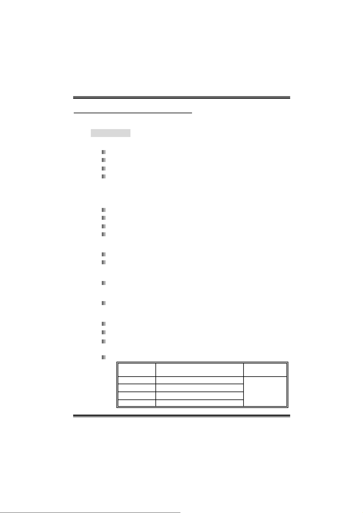
DI MM Socket
Location
DDR2_A1 256MB/512MB/1GB/2GB/4GB*1
DDR2_A2 256MB/512MB/1GB/2GB/4GB*1
DDR2_B1 256MB/512MB/1GB/2GB/4GB*1
DDR2_B2 256MB/512MB/1GB/2GB/4GB*1
DDR Module
1
To t a l Mem or y
Size
Max is 16GB.
Page 4

N4SIE-A7
Ex p an sion Slo ts
Three 32bit PCI bus master slots.
Normal Mod e PCI-Exp ress slots:
- One PCI-Express x16 slot: PCI_EX16-1.
- Two PCI-Express x1 slots: PCI-EX1-1 and PCI-EX1-2.
SL I Mode PCI-Express sl ots:
- Two PCI-Express x8 slots: PCI-EX16-1 and PCI-EX16-2.
- Two PCI-Express x1 slots. PCI-EX1-1 and PCI-EX1-2.
Not ice:
Normal Mode and SLI Mode are switched by SLI-NF4T selector card.
(Please read Chapter 5 for detail inf ormation.)
Gigabit Ethernet LAN
NVIDIA Gigabit MAC + VIT ESSE Gigabit PHY VSC8201.
Supports 10Mb/s, 100Mb/s and 1GB/s auto-negotiation.
Ha l f / Full d upl e x ca pa bili ty.
Supports personal Firewall setup.
Su pp ort s ACP I power mana geme nt.
On Boar d AC’97 So und Co d ec
Chi p: AL C850.
Supports 8 channels.
Supports SPDIF-Out and SPDIF-In (optional) functions.
Compliant with AC’97 version 2.3 specification.
Super I/O
Chip: ITE IT8712F.
Low Pin Count Interface.
Provides the most commonly used legacy Super I/O
functionality.
Environment Control initiatives,
H/W Monitor
Fan Speed Controller
ITE's "Smart Guardian" function
IEEE 1394 Chip (optional)
Ch i p: V IA VT 63 07.
Su pp ort s two 1394 A Fi rewi re p o rts up to 40 0M b /s indi vidu all y.
2
Page 5

N4SIE-A7
Serial AT A II
Controller integrated in NF4-SLI-MCP.
Supports RAID functions.
Supports Serial ATA 2.0 specification.
Supports 4 Serial ATA (SATA) devices.
Data transfer rate up to 1.5GB/s or 3GB/s.
RAID Controll er
Controller integrated in NF4-SLI-MCP.
NVIDIA RAID Technology:
- RAID 0 disk striping for highest system and application
performance
- RAID 1 disk mirroring support for fault tolerance
Support for both SATA and ATA-133 disk controller
standards
On Board IDE
Two on-board connectors support 4 devices.
Supports Ultra DMA Modes 6~0 (Ultra DMA –133/100/60/33).
Supports standard PIO Modes 4~0.
Internal On-board I/O Connectors and Headers
1 front panel header supports front panel facilities.
1 CD-in connector supports 1 CD-ROM audio-in device.
1 front audio header supports front panel audio-out function.
1 chassi s open header supports PC case-opened warning
function.
1 S/PDIF-out connector supports digital audio-out function
1 S/PDIF-in connector supports digital audio-in function
(optional).
1 1394A header supports 1 1394A Firewire port at front panel
(optional).
1 Floppy port supports 2 FDD with 360K, 720K, 1.2M, 1.44M
and 2.88Mbytes.
2 IDE connectors support 4 hard disk devices.
3 USB headers support 6 USB 2.0 ports.
4 serial ATA II connectors support 4 SATA I/II devices.
3
Page 6
N4SIE-A7
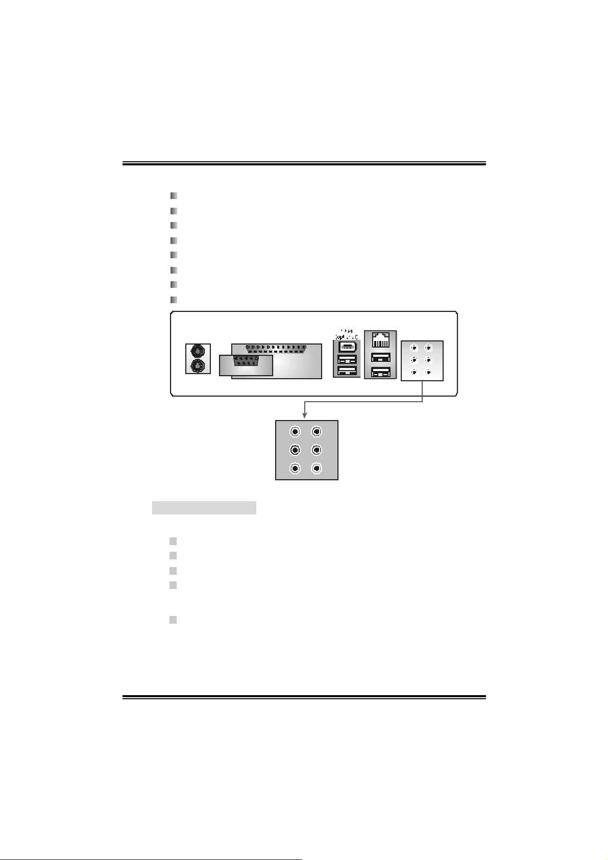
Back Panel I /O Connectors
1 Serial port.
1 P a rallel port.
1RJ-45 LAN jack.
1 PS/2 Mouse port.
1 PS/2 Keyboard port.
1 1394A Firewire port (optional).
4 USB 2.0 ports.
6 audio ports support 8 channels audio-out facilities.
PS/2
Mouse
PS/2
Keyboard
C
O
M
COM1
Center/Left
Parallel Por t
1
Rear
Side
Parallel
USB x2
Line-in
Line-out
MIC- in
LAN
USB x2
B. BIOS & Software
BIOS
Award legal BIOS.
Supports APM1.2.
Supports ACPI.
Supports USB Function.
Software
Supports Warpspeeder™, 9th Touch™, WINFLASHER™ and
FLASHER™.
4
Page 7

N4SIE-A7
1.2 PACKAGE CHECKLIST
FDD Cable x 1
HDD Cab l e x 1
User ’ s M anu al x 1
Serial ATA Cable x 1
BRI-2 SLI Bridge x 1
Fully Setup Driver CD x 1
Rear I/O Panel for ATX Case x 1
SLI-NF4T Selector Card x 1 (pre-installed)
SPDIF Ca ble x 1 (o ptio nal )
USB 2.0 Cable x 1 (optional)
Retention Bracket x 1 (optional)
IEEE 1394A Cable x 1 (optional)
Serial ATA Power Switch Cable x 1 (optional)
5
Page 8
N4SIE-A7
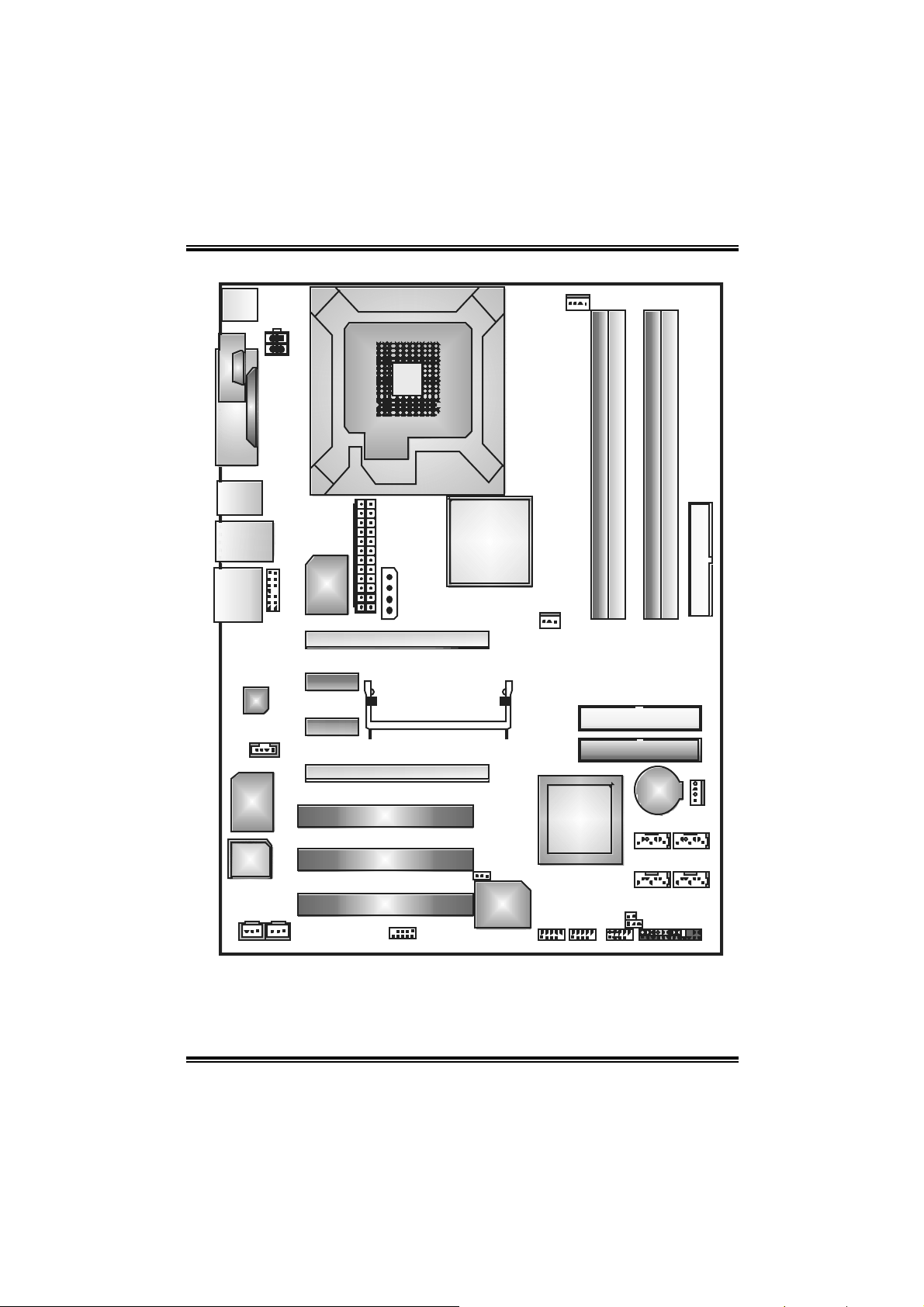
1.3 LAY OUT AND COMPONE NTS
J KBMS1
JCOM1
C
C
O
O
M
M
1
1
Parallel Port
J1394_USB1
JATXPWR2
J PRNT 1
LGA775
CPU1
JAT XP WR1
JCFAN1
DDR2_A1
DDR2_A2
DDR2_B1
DDR2_B2
JUSBL AN1
EARPHONEJACK 1
Codec
Super
I/O
JAUDI OF1
JCDIN1
Giga
LAN
PCI-Ex1_1
PC I-Ex1_2
BIOS
JSPDIF_IN1
JS PD IF _OUT 1 J13 94A 1
(o pti o nal)
Note: ■ represents the 1
JAUXPWR1
JAUXPWR1
PC I-E x16-1
PCI-Ex 16-2
PCI1
PC I2
PC I3
st
pin .
NF4-SLI-SPP
SLI1
J1394PWR1
IEEE1394
Chip
(opt ional)
FAN1
NF4-SLI-MCP
JUSB1 JUSB2 JUSB3
IDE 2
ID E1
JSFAN1
BAT 1
SATA1SATA2
S ATA 4 S AT A3
JCI1
JCMOS1
JPANEL1
FDD1
6
Page 9
N4SIE-A7
CHAPTER 2: HARDWARE INSTALLATION
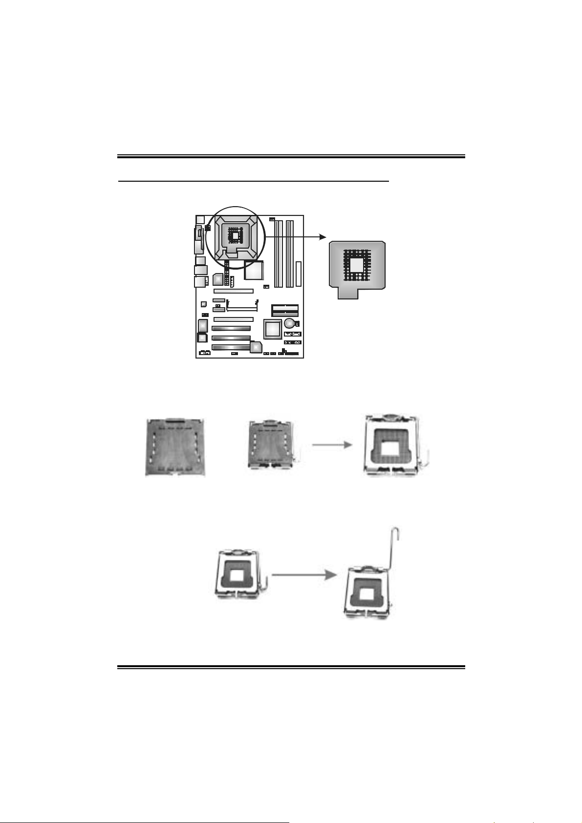
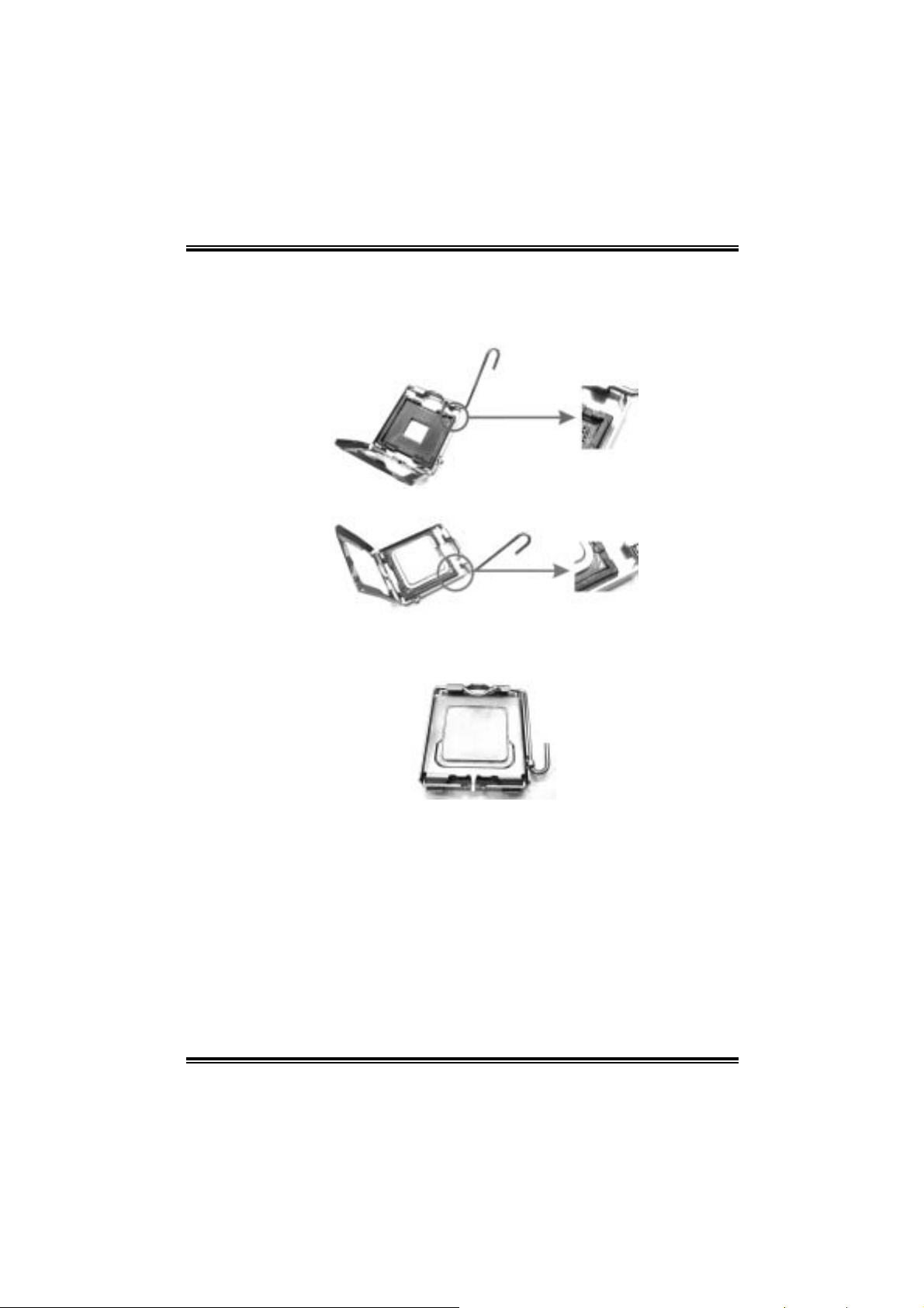
2.1 INSTALL ING CENTRAL PROCESSING UNIT (CPU)
CPU1
Spe cial Notice:
Remove Pin Cap before installation, and make good preservation for future use.
When the CPU is removed, cover the Pin Cap on the empty socket to ensure pin
legs won’t be damaged.
pin cap
Step 1: Pull the lever sideways away from the socket and then raise the
lever up to a 90-degree angle.
7
Page 10
N4SIE-A7
Step 2: Look for the black cut edge on socket, and the white dot on CPU
should point forwards this black cut edge. The CPU will fit only in
the correct orientation.
Step 2-1:
Step 2-2:
Step 3: Hold the CPU down firmly, and then close the lever to complete
the installation.
Step 4: Put the CPU Fan on the CPU and buckle it. Conne ct the CPU
FAN power cable to the JCFAN1. This completes the installation.
8
Page 11
N4SIE-A7
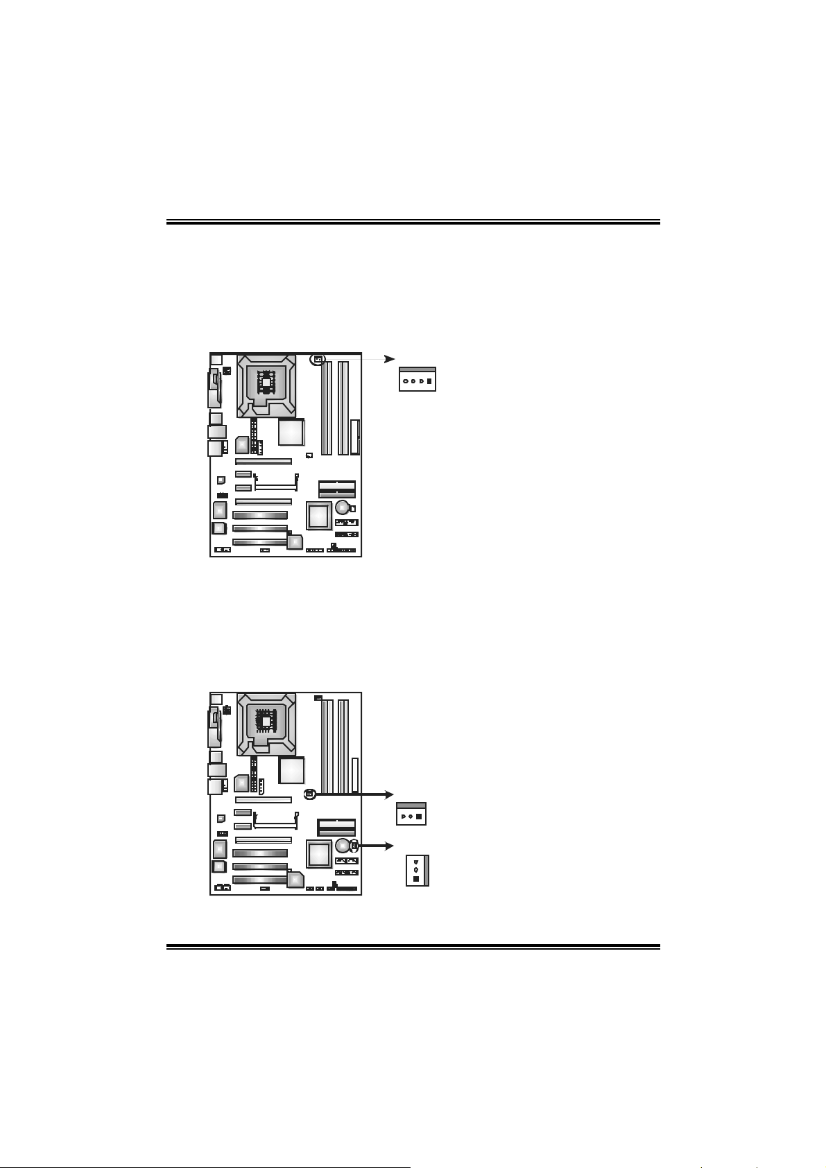
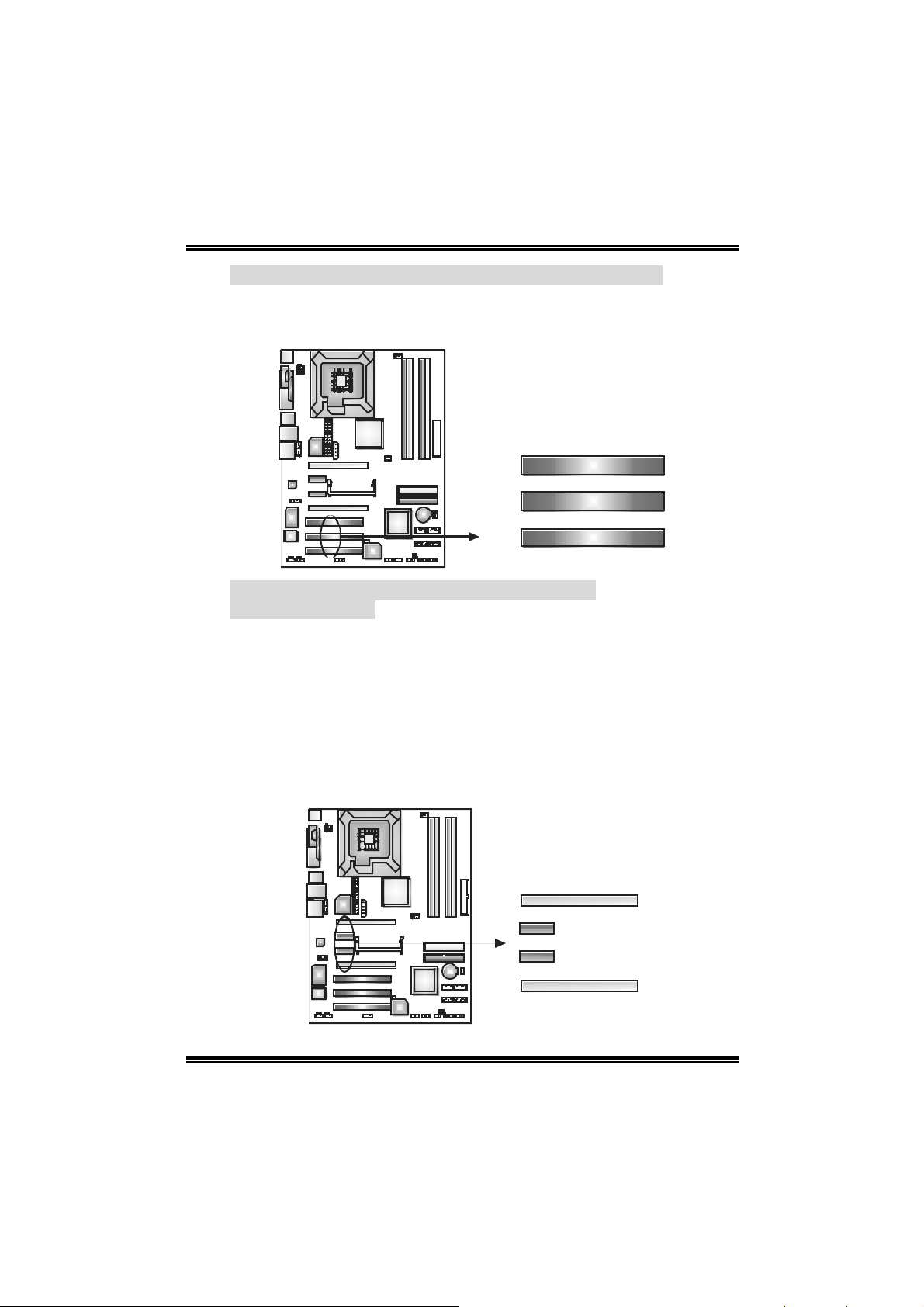
2.2 FAN HEADERS
These fan headers support cooling-fans built in the computer. The fan
wiring and plug may be different according to the fan manufacturer.
Connect the fan cable to the connector while matching the black wire to
pin#1.
JCFAN1: CPU Fa n Power Header
JCFAN1
14
Pin
1 Ground
2 +12V
3 FAN RPM rate
4 Smart Fan Control
Note:
The JCFAN1support s system cooling fan with Sm art Fan Control utility. I t supports
4 pin head c onnector. When connecting with wires onto connectors, please note
that the red wire is the positive and should be connected t o pin#2, and the black
wire is Ground and s hould be connected to GND.
Assignment
sense
FAN1: No rth Bridge Fan Power He ader
JSFAN 1: Sy s te m F an P o wer H e a der
FAN1
13
JSFAN1
3
1
9
Pin
1 Gr oun d
2 +12V
3 FAN RPM rate
Assignment
sense ( opti onal)
Page 12
N4SIE-A7
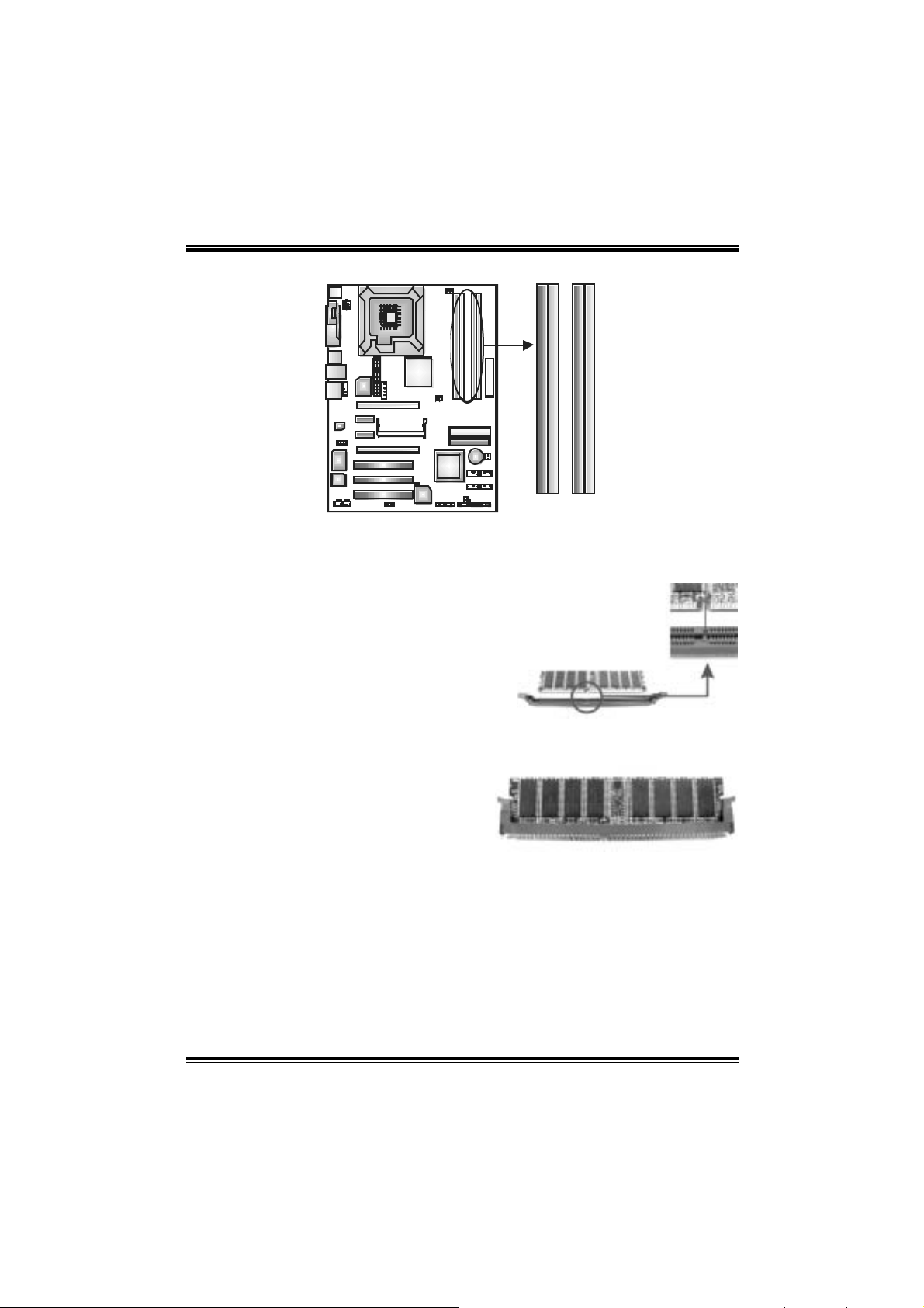
2.3 INSTALL ING SYSTEM MEMORY
DDR2_A1
DDR2_B1
DDR2_A2
DDR2_B2
1. Unlock a DIMM slot by pressing the retaining clips outward. Align a
DIMM on the slot such that the notch on the DIMM matches the break
on the Slot.
2. Insert the DIMM vertically and firmly into the slot until the retaining
chip snap back in place and the DIMM is properly seated.
10
Page 13
N4SIE-A7
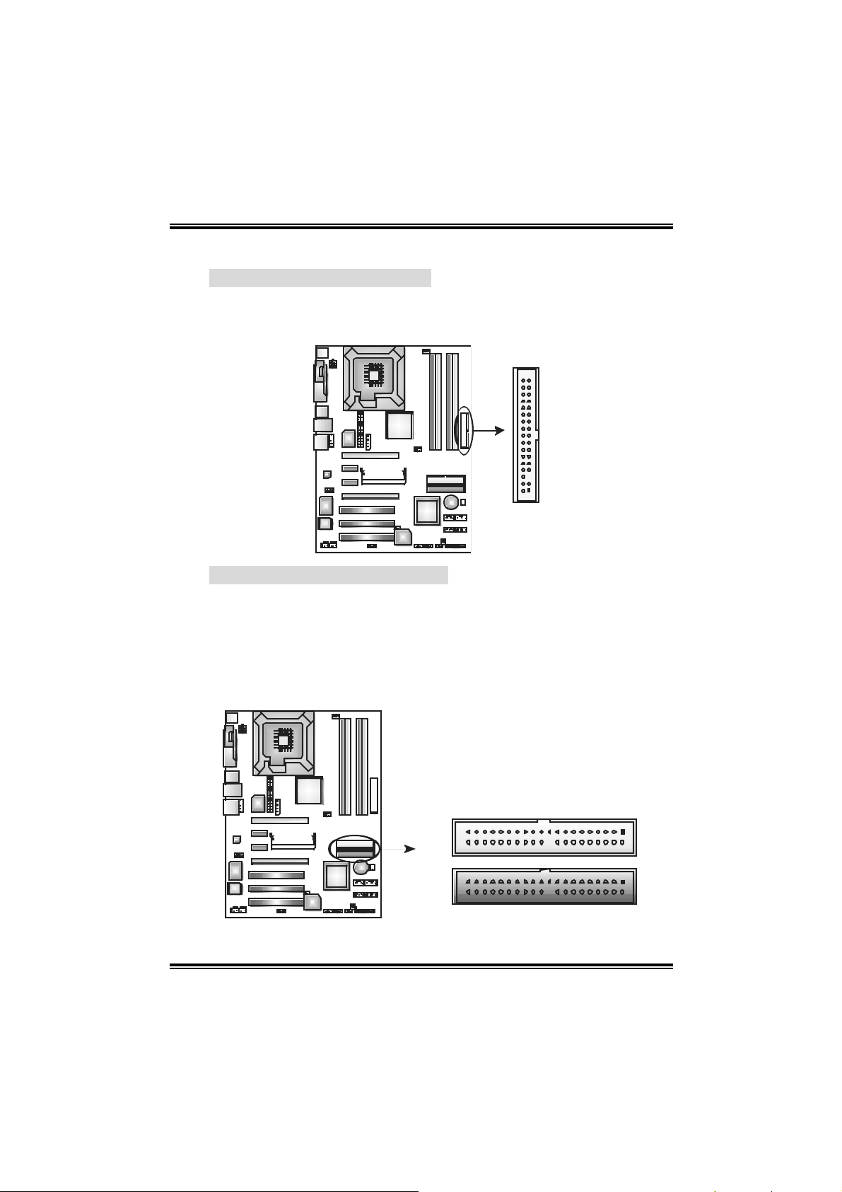
2.4 CONNECTO RS AND SLOTS
FDD1: Floppy Disk Connector
The motherboard provides a standard floppy disk connector that
supports 360K, 720K, 1.2M, 1.44M and 2.88M floppy disk types.
This connector supports the provided floppy drive ribbon cables.
3334
12
IDE1/IDE2: Hard Disk Connector
The motherboard has two 32-bit Enhanced PCI IDE Controller that
provides PIO Mode 0~5, Bus Master, and Ultra DMA 33/66/100/133
functionality. It has two HDD conne ctors IDE1 (primary) and IDE2
(secondary).
The IDE connectors can connect a master and a slave drive, so you
can connect up to four hard disk drives. The first hard drive should
always be connected to IDE1.
IDE2
IDE1
11
139
240
Page 14
N4SIE-A7
PCI1~PCI3: Peripheral Co mponent Interconnect S lots
This motherboard is equipped with three standard PCI slots. PCI
stands for Peripheral Component Interconnect, and it is a bus
standard for expansion cards. This PCI slot is designated as 32 bits.
PCI1
PCI2
PCI3
PCI-EX16-1/PCI-EX16-2/PCI-EX1-1/PCI-EX1-2 :
PCI-Express Slots
PCI-EX16-1 (No rmal Mode):
- PCI Express 1.0a compliant.
- Maximum bandwidth is up t o 4GB/s per direction.
PCI-EX1-1/PCI-EX1-2 (No rmal Mode):
- PCI Express 1.0a compliant.
- Maximum bandwidt h is up to 250MB/s per direct ion.
PCI-EX16-1/PCI -EX16-2 (SLI Mo de ):
- PCI Express 1.0a compliant.
- Maximum bandwidth is up to 2GB/s per direction.
12
P CI- EX16- 1
P CI- EX1_1
P CI- EX1_2
P CI- EX16- 2
Page 15
N4SIE-A7
CHAPTER 3: HEADERS & JUMPERS SETUP
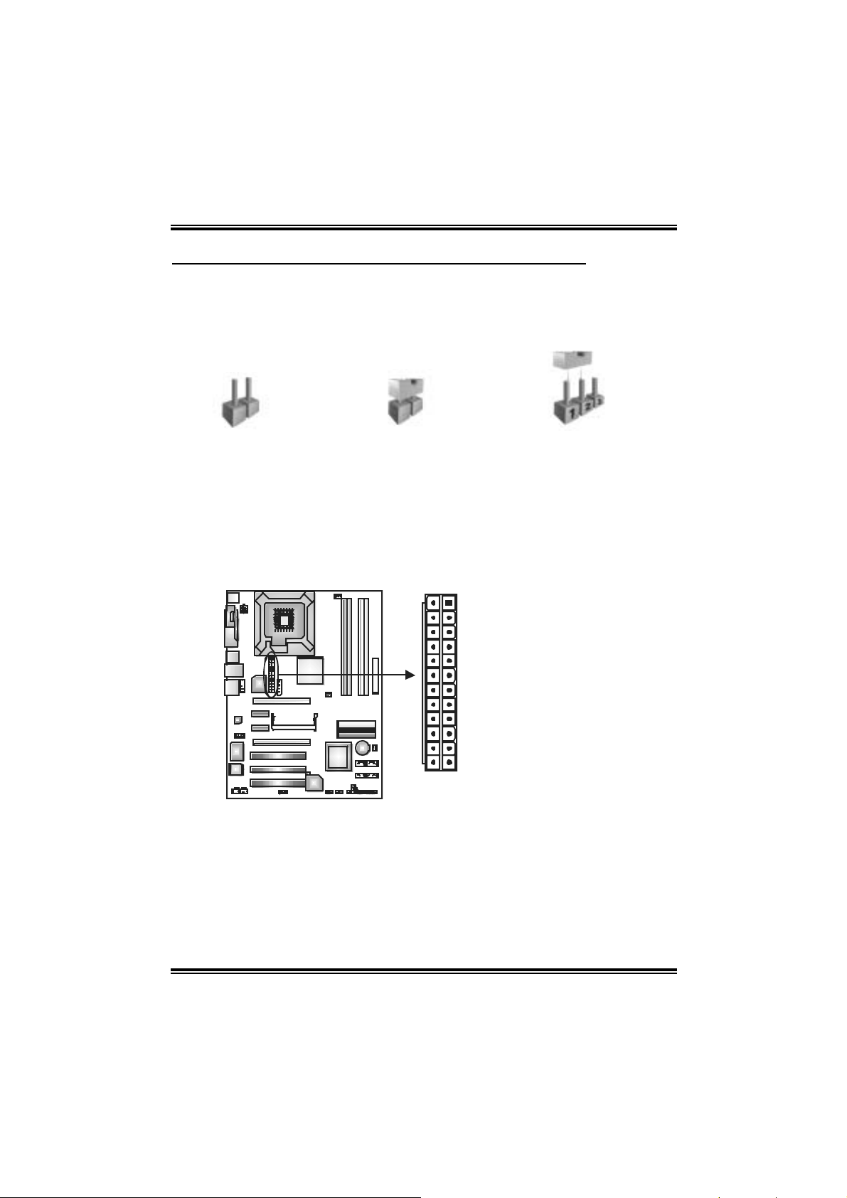
3.1 HOW TO SETUP JUMPERS
The illustration shows how to set up jumpers. When the jumper cap is
placed on pins, the jumper is “close”, if not, that means the jumper is
“open”.
Pin opened Pin closed Pin1-2 closed
3.2 DETAIL SETTINGS
JAT XPWR1 : AT X Power Con nector
This connector allows user t o connect 20-pin power c onnector on the ATX
power supply .
Pin Assignment
1 +3.3V
2 +3.3V
3 Ground
13
1
1224
4 +5V
5 Ground
6 +5V
7 Ground
8 PW_OK
9 Standby Voltage+5V
10 +12V
11 +12V
12 +3.3V
13 +3.3V
14 -12V
15 Ground
16 PS_ON
17 Ground
18 Ground
19 Ground
20 NC
21 +5V
22 +5V
23 +5V
24 Ground
13
Page 16
N4SIE-A7
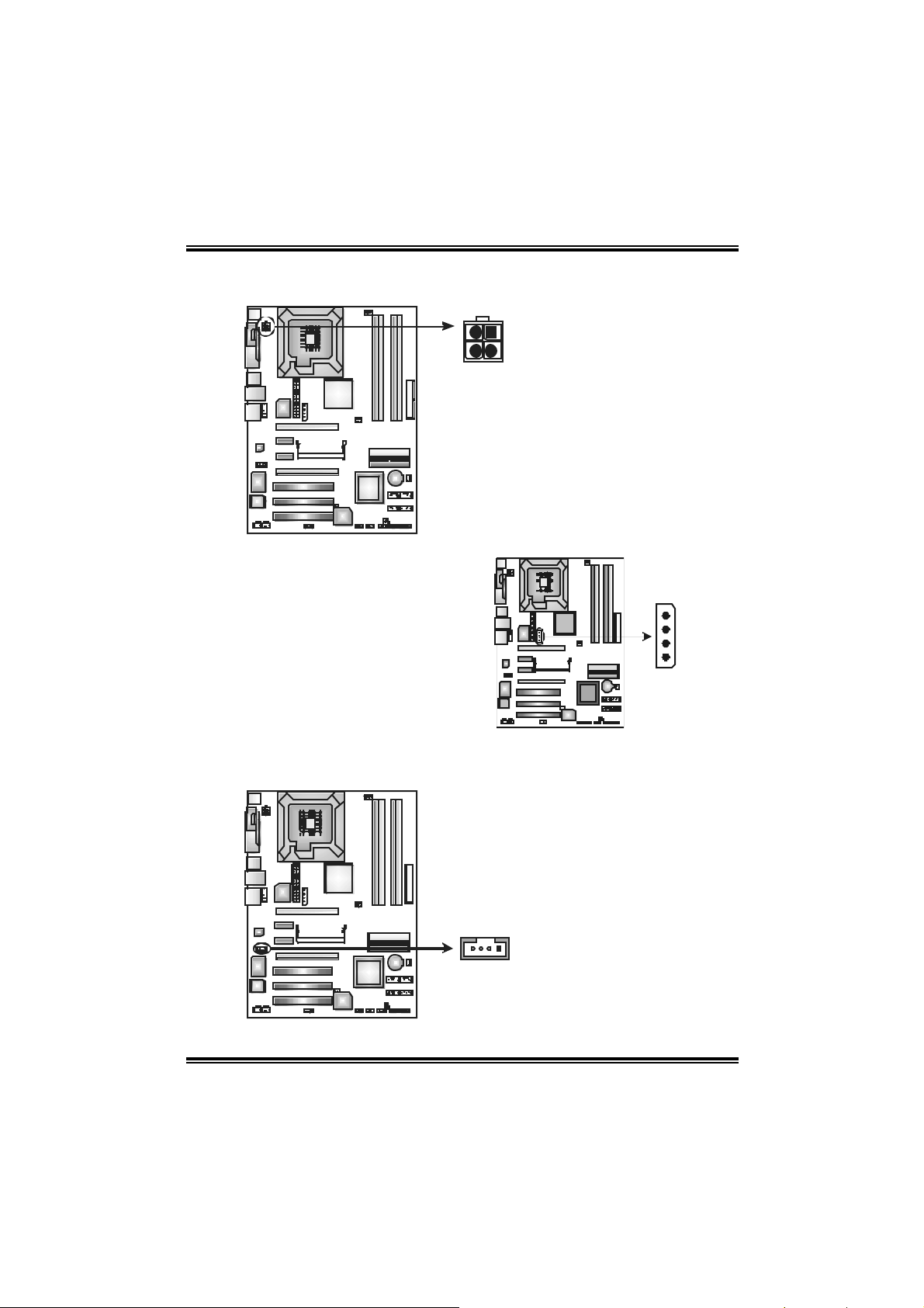
JATXPW R2 : ATX Po w er S o urce Conn ector
By connect ing this connector, it will prov ide +12V to CPU power circ uit.
2
JAUXPWR1:
PCI - E xpress x 1 6 S l o t P o wer Sou rce
Connector
When SLI mode is enabled, please
plug in this PEX power source
connector to mak e sure the syst em is
working under a s table env ironment.
Please read Chapter 5 for detail
inf orm ation.
1
43
Pin
Assignment
1 +12V
2 +12V
3 Ground
4 Ground
Gr ou nd
Gr ou nd
+1 2V
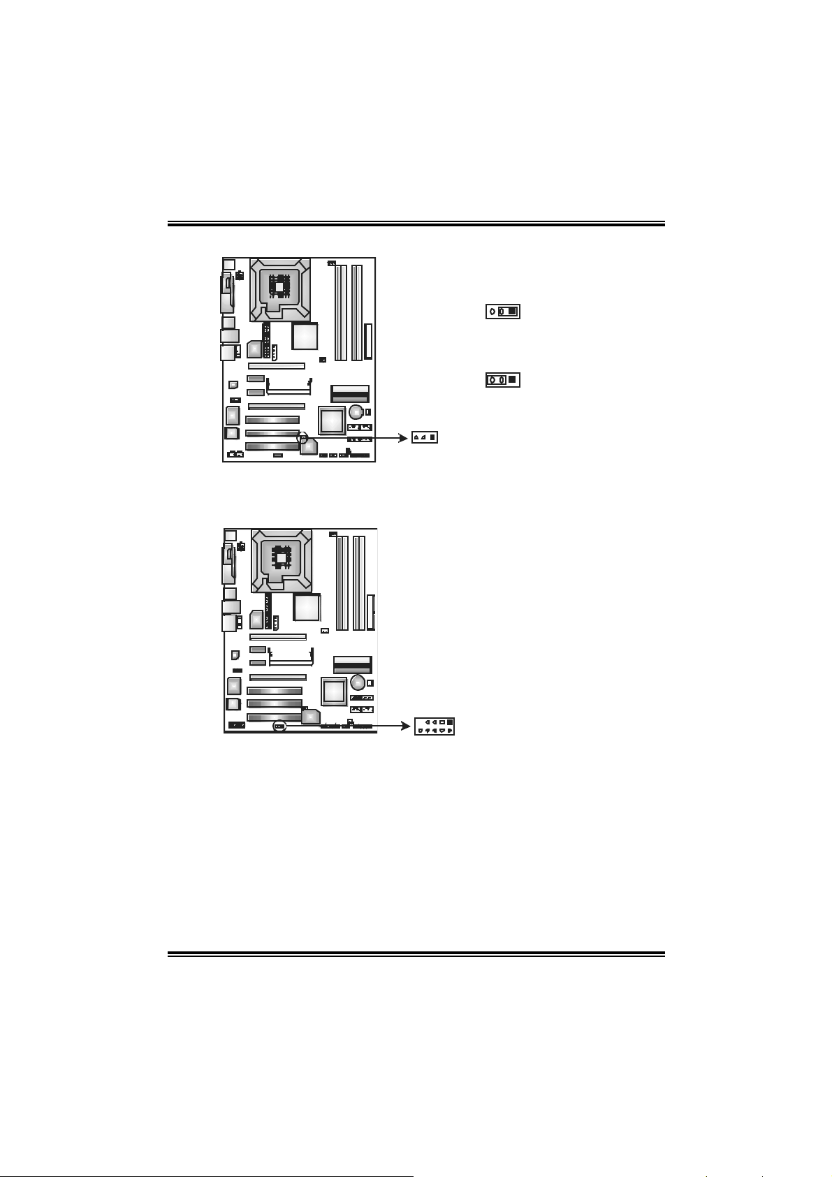
JCDIN1 : CD-ROM Aud i o -in Conn ector
This connector allows user to connect the audio source f rom the variety dev ices,
like CD-ROM, DVD-ROM, PCI sound c ard, PCI TV turner card etc..
Pin
Assignment
1 Left channel input
2 Ground
3 Ground
4 Right channel i nput
14
14
Page 17
N4SIE-A7
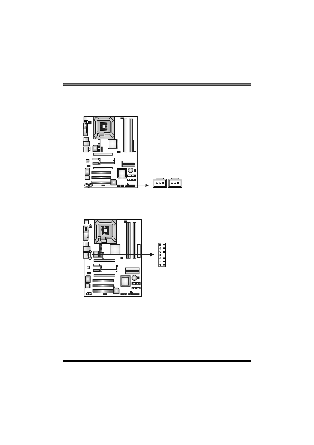
JSPDIF_OUT/JS PDIF_IN1: Digital Au di o-out Connectors
(JSPDIF_IN1 is optional . )
These connectors allow user t o connect the PCI brac ket SPDIF output or input
header.
JSPDIF_OUT:
Pin Assignment
1 +5V
2 SPDIF OUT
3 Ground
JSP DIF_IN1 (optional):
Pin Assignment
JSPDIF_I N1
(opti onal)
JSPDIF_OUT1
1 +5V
2 SPDIF IN
3 Ground
13 13
JAUDIO 2 : Fron t Panel Au d i o -ou t Header
This connector will allow user to c onnect with the front audio out put headers on
the PC case. It will disable the output on back panel audio c onnectors.
Pin Assignment
1 MIC-in/ Stereo MIC-in R
2 Ground
3 Stereo MIC-in L
4 Audio power
1132
14
5 Right line-out/
Speaker-out Right.
6 Right line-out/
Speaker-out Right
7 Reserved
8 Key
9 Left line-out/ Speaker-out
Left
10 Left line-out/ Speaker-out
Left
11 Right line-in
12 Right line-in
13 Left line-i n
14 Left line-i n
15
Page 18
N4SIE-A7
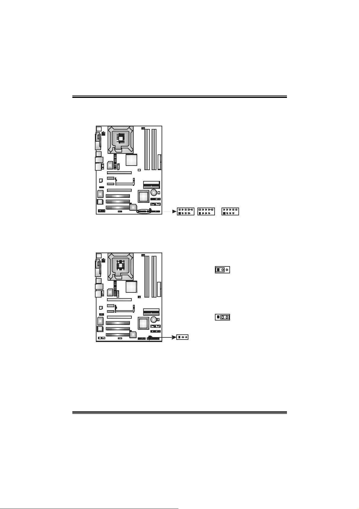
J1394PWR1 (optional): Power Sou rce H ea der f o r 1394 Chip
3
1
Pin 1-2 Close:
+3.3V for 1394 chips et (default).
3
1
Pin 2-3 Close:
+3.3V SB for 1394 c hipset.
13
J1394A1 (optional): Header for 1394A Firewire Port at Front Panel
This connector allows user t o connect the f ront 1394 port f or digital image
dev ic es.
Pin
Assignment
1 A+
2 A3 Ground
4 Ground
5 B+
6 B7 +12V
8 +12V
9 Key
10 Ground
19
16
210
Page 19
N4SIE-A7
JUSB1~JUSB 3: Headers f or USB Ports at Front Panel
This connector allows user t o connect additional USB cables at PC front panel,
and also can be c onnected with internal USB dev ices, like USB card reader.
Pin
1 +5V (fused)
2 +5V (fused)
3 USB4 USB5 USB+
6 USB+
7 Ground
8 Ground
9 Key
JUSB1
1
102
JUSB2 JUSB3
9
10 NC
JCMOS1: C l ea r CMOS Hea der
By placing the jumper on pin2-3, it allows user to restore t he BIOS saf e s etting
and the CMOS data, please caref ully follow the procedures to av oid damaging
the motherboard.
13
Pin 1-2 close:
Normal Operation (Default).
Assignment
3
1
Pin 2-3 close:
Clear CMOS data.
13
Clear CMOS Procedures:※
1. Remov e AC power line.
2. Set the jumper to “Pin 2-3 close”.
3. Wait for five seconds.
4. Set the jumper to “Pin 1-2 close”.
5. Power on the AC.
6. Reset the desired password or clear the CMOS data.
17
Page 20
N4SIE-A7
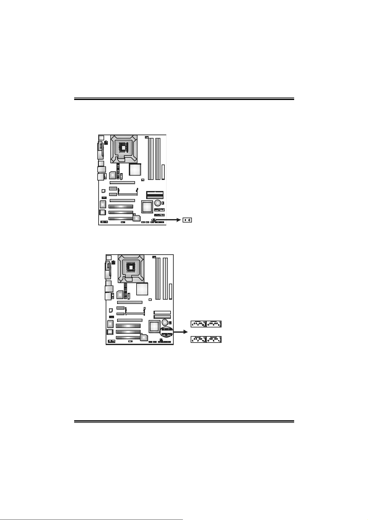
JCI1 : C a s e O pen H eaders
This connector allows sy stem to monitor PC case open st atus. If the signal has
been triggered, it will rec ord to the CMOS and s how the message on next
boot-up.
Assignment
Pin
1 Case open signal
2 Ground
12
JS AT A1~J S AT A4 : S erial AT A Conn ectors
The motherboard has a SATA Controller in NVI DIA Crush19 with 4 c hannels
SATA int erface, it satisfies the SATA 2.0 s pec and with t ransf er rate of 3.0Gb/s.
Assignment
Pin
1 Ground
2 TX +
3 TX 4 Ground
5 RX6 RX+
SATA1SATA2
7 Ground
18
147147
SATA3SATA4
Page 21
N4SIE-A7
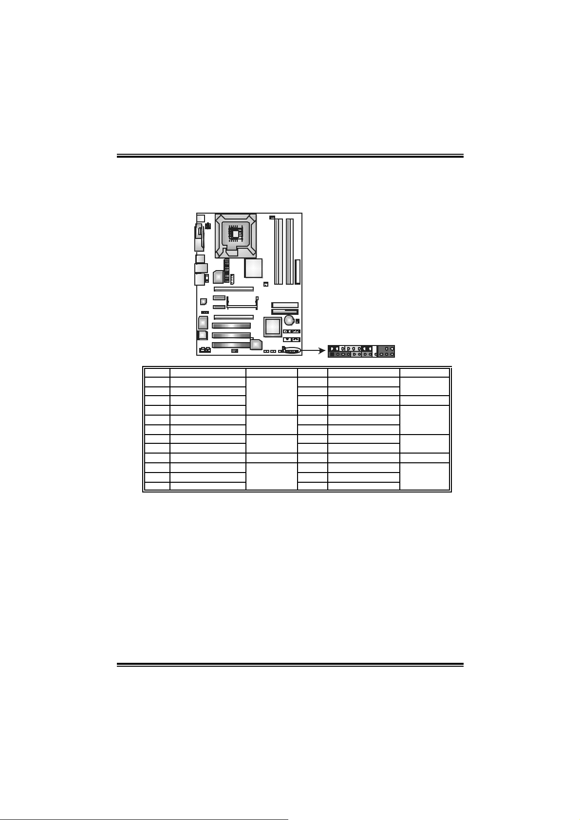
JPANEL1: Header for Front Panel Facilities
This 24-pin connector includes Power-on, Reset, HDD LED, Power LED, Sleep
button, speaker and IrD A Connection. It allows user to connect the PC case’s
front panel switch f unctions.
242
1
Pin Assignment Function Pin Assignment Functio n
1 +5V 2 Sleep control
3 N/A 4 Ground
5 N/A 6 N/A N/A
7 Speaker
9 HDD LED (+) 10 Power LED (+)
11 HDD LED (-)
13 Ground 14 Power button
15 Reset control
17 N/A 18 Key
19 N/A 20 Key
21 +5V 22 Ground
23 IRTX
Speaker
Connector
Hard dri ve LED
Reset button
IrDA Connector
8 P o we r LE D (+)
12 P o we r LED (-)
16 Ground
24 IRRX
23
Sleep button
Power LED
Power-on
button
IrDA Connector
19
Page 22

N4SIE-A7
CHAPTER 4: USEFUL HELP
4.1 AWARD BIOS BEEP CODE
Beep Sound Meanin g
One long beep f ollowed by two short
beeps
High-low siren sound CPU overheat ed
One Short beep when system boot-up No error found during POST
Long beeps every other second No DRAM detected or inst all
4.2 EXTRA INF OR MATION
A. BIOS Update
After you fail to update BIOS or BIOS is invaded by virus, the
Boot-Block function will help to restore BIOS. If the following message
is shown after boot-up the system, it means the BIOS contents are
corrupted.
Video card not f ound or v ideo card
memory bad
System will shut down automatically
In this Case, please follow the procedure below to restore the BIOS:
1. Make a bootable floppy disk.
2. Download the Flash Utility “AWDFLASH.exe” from the Biostar
website: www.biostar.com.tw
3. Confirm motherboard model and download the respectively
BIOS from Biostar website.
4. Copy “AWDFLASH.exe” and respectively BIOS into floppy disk.
5. Insert the bootable disk into floppy drive and press Enter.
6. System will boo-up to DOS prompt.
7. Type “Awdfla sh xxxx.bf / sn/py/ r” in DOS prompt.
8. System will update BIOS automatically and restart.
9. The BIOS ha s been recove red an d will work properl y.
20
Page 23

N4SIE-A7
B. CPU Overheated
If the system shutdown automatically after power on system for
seconds, that means the CPU protection function has been activated.
When the CPU is over heated, the motherboard will shutdown
automatically to avoid a damage of the CPU, and the system may not
power on again.
In this case, please double check:
1. The CPU cooler surface is placed evenly with the CPU surface.
2. CPU fan is rotated normally.
3. CPU fan speed is fulfilling with the CPU speed.
After confirmed, please follow steps below to relief the CPU protection
function.
1. Remove the power cord from power supply for seconds.
2 . Wa i t f o r se c o nd s.
3. Plug in the power cord and boot up the system.
Or you can:
1. Clear the CMOS data.
(See “Close CMOS Header: JCMOS1” section)
2 . Wa i t f o r se c o nd s.
3. Po we r on th e system agai n.
21
Page 24

N4SIE-A7
e
4.3 TROUBL ESHOOTING
Probable Solution
1. No power to the sy stem at all
Power light don’t illuminat e, f an
inside power s upply does not turn
on.
2. Indicator light on key board does
not turn on.
System inoperativ e. Keyboard lights
are on, power indic ator lights are lit,
and hard driv e is s pinning.
System does not boot from hard disk
driv e, can be booted f rom optical driv e.
System only boots f rom optical driv e.
Hard disk can be read and applicat ions
can be used but booting from hard disk
is impossible.
Screen mess age says “Invalid
Configuration” or “CMOS Failure.”
Cannot boot sy stem after installing
second hard driv e.
1. Make sure power cable is
securely plugged in.
2. Replace cable.
3. Contact technical support.
Using even pressure on both ends of
the DIMM, press down firm ly until the
module snaps into plac e.
1. Check cable running from disk to
disk cont roller board. Make sure
both ends are s ecurely plugged
in ; c hec k t he d r iv e ty p e i n t h e
standard CMOS s etup.
2. Backing up the hard drive is
extremely important. All hard
disks are capable of breaking
down at any time.
1. Back up data and applications
files.
2. Ref ormat t he hard driv e.
Re-install applications and data
using backup disks.
Review system ’s equipment. Make sur
correct inf ormation is in setup.
1. Set master/slave jumpers
correctly.
2. Run SETUP program and selec t
correct driv e types. Call the driv e
manufacturers f or c ompatibility
with other drives.
22
Page 25

N4SIE-A7
CHAPTER 5: NVIDIA SLI FUNCTION
5.1 REQUIREM ENT S
Only Windows XP supports SLI (Dual Video) function.
Two identical SLI-ready graphics cards that are NVIDIA certified.
The graphics card driver should support NVIDIA SLI technology.
The power supply unit must provide at least the minimum power
req ui red by the system , or the system will be unstable.
5.2 PL ACING T HE SLI-NF4T SELECTOR CARD
There is a pre-installed SLI-NF4T selector card on the motherboard.
The default setting is Normal Mode, only supports single graphics
card.
To use two graphics cards, firstly, you have to set the selector card to
SLI Mode, to support dual video cards.
Step 1: Push the retention clips outward to release SLI-NF4T selector
card.
Step 2: Pull the selector card out of the slot.
23
2 pull o ut t he
○
selector c ard
1 about 45
○
O
degree lift.
Page 26

N4SIE-A7
Step 3: Invert the selector card and insert the edge labeled “SLI
MODE”.
Step 4: Push down the selector card until the retention clips snap into
place.
1 Inser t t he card with a
○
degr ee abo ut 45
0
.
2 Push the selec tor
○
Not ice: Make sure to insert the card into the slot completely.
24
card downward.
Page 27

N4SIE-A7
5.3 THINGS TO NOTICE
No r m a l Mod e:
- Only PEX16-1 slot supports PCI-Express x16 interface graphics
card function.
- PEX1-1 and PEX1-2 slots provide PCI-Express x1 interface
expansion card function.
SLI Mo de :
- Use BRI-2 connector to link two SLI-ready PCI-E x16 interface
graphics cards.
- Both PEX16-1 and PEX16-2 slots provide PCI-E x8 data transfer
rate.
- PEX1-1 and PEX1-2 slots provide PCI-Express x1 interface
expansion card function.
- Coordinate with graphics card driver to set Dual Video function.
5.4 INSTALL ING SLI-READY GRAPHICS CARDS
Step 1: Make sure the SLI-NF4T selector card is placed at SLI Mode.
Step 2: Prepare two graphics cards with PCI-E x16 interface.
Step 3: Insert the first one graphics card into the yellow slot
(PCI-EX16-1). And then insert the second graphics card into the white
slot (PCI-EX16-2).
PEX16-1
PEX16-2
Not ice:
Make sure both t he graphics cards are seated into slots completely.
25
Page 28

N4SIE-A7
Step 5: Connect a 4-pin ATX power cable to AUX power connector
(JAUXPWR1), this will ensure the stabilization of your system.
Notice:
When under SLI m ode, please make sure the
power supply is at least 500W (and above).
St ep 6: Insert the SLI Brid ge (BRI-2) con necto r on the gold -fi n gers of
ea c h g rap hi cs ca rd .
Gold-f ingers on
two graphics
Not ice:
Please make good preserv ation of this bridge f or f uture use.
Step 7: To securely fix the connector between two graphics cards, a
retention bracket must be installed.
Step 7-1: Remove any of the bracket cover between the two
graphics cards.
Step 7-2: Align and insert the retention bracket into the slot
and then fix it with a screw.
Not ice:
Make sure the ret ention bracket supports the SLI Bridge (BRI-2)
firmly.
26
Page 29

N4SIE-A7
5.5 ENABLING MULTI-GPU FEAT U RE IN WINDOWS
After the graphics cards are installed, enable the Multi-GPU feature in
NVIDIA nView properties.
Step 1:
Click NVIDIA Settings icon on the
Windows taskbar.
Step 2:
Select “nView Properties” in nView
Desktop Manager pop-up menu.
Step 3:
Cli ck “Properties” icon in Desktop
Management tab to display properties
dialog box.
Step 4:
Click “Advanced” icon in Settings tab.
27
Page 30

N4SIE-A7
Step 5:
Select “NVIDIA GeForce” tab, and then
click on “Multi-GPU” item on the left dialog
box.
Step 6:
Check before “Enable SLI
multi-GPU” item, and click on
OK to complete the setting.
28
Page 31

N4SIE-A7
CHAPTER 6: NVIDIA RAID FUNCTIONS
6.1 OPERATION SYSTEM
Supports Windows XP Home/Professional Edition, and Windows 2000
Professional.
6.2 RAID ARRAYS
NVRAID supports the following types of RAID arrays:
RAID 0: R AID 0 defines a disk striping scheme that improves disk read and writes
times for many applications.
RAID 1: R AID 1 defines techniques for mirroring data.
RAID 0+ 1 : RAID 0+1 combines the techniques used in R AID 0 and RAID 1.
S p a nn i ng (JB O D): JB OD provides a m ethod for combining drives of different
sizes in to one large disk.
6.3 HOW RAID WORKS
RAID 0:
Th e co n t r oller “ s trip es ” d ata acro s s
multiple drives in a RAID 0 array
sy s tem . It break s u p a l arg e fil e i n to
smaller blocks and per forms di sk reads
and writes across multiple drives in
parallel . The s i ze o f each blo ck i s
determined by the strip size parameter,
which you set during t he creat ion of the
RAID set based on the system
environment. T his technique reduces
ov eral l d is k acces s time and offers high
bandwidth.
Fea tures and Be nefits
- Drives: Minimum 1, and m aximum is up to 6 or 8. Depending on t he
platform.
- Uses: I ntended f or non-crit ical data requiring high data throughput, or any
env ironm ent that does not require f ault tolerance.
- Benefits: prov ides increased data throughput, especially f or large files.
No capacity loss penalty for parity.
- Drawbacks: Does not deliver any fault tolerance. If any drive in the array
f ails , all data is lost .
- Fa ult Tolerance: No.
Blo ck 1
Block 3
Block 5
Blo ck 2
Block 4
Block 6
29
Page 32

N4SIE-A7
RAID 1:
Every read and write is actually carried out in paral lel across 2 disk drives in a
RAID 1 array system. T he mirrored (backup) copy o f the data can reside on the
same disk or on a second redundant drive in the array. RAID 1 provides a
hot-standby copy of data i f the active
volume or drive is corrupted or becomes
unavailable because o f a hardw are
failure.
RAID techni ques can be applied for
high-availability solutions, or as a form
of automatic backup that eliminates
tedious manual backups to more
expensive and less reliable media.
Fea tures and Be nefits
- Drives: Minimum 2, and maximum is 2.
- Uses: RAID 1 is ideal f or small databases or any other application that
requires f ault tolerance and minimal c apacity.
- Benefits: Prov ides 100% data redundancy. Should one driv e fail, the
controller switches to t he other drive.
- Drawbacks: Requires 2 driv es f or the storage space of one driv e.
Perf orm ance is impaired during driv e rebuilds.
- Fault Tolerance : Yes.
Blo ck 1
Block 2
Block 3
Blo ck 1
Block 2
Block 3
S p anning (JBOD):
JBO D s tan d s for “ Ju s t a Bu n ch o f Di s k s ”. Each dr i v e i s acces s ed as if it w ere
on a standard S CS I host bus
adap t er. Thi s is u s eful w hen a
single drive configur ation i s
needed, but it offers no speed
improvement or fault tolerance.
Fea tures and Be nefits
- Uses: JBOD works best if you hav e odd sized driv es and y ou want to
combine them to mak e one big drive.
- Benefits: J BOD prov ides t he ability to com bine odd size driv es us ing all of
the capacity of the driv es .
- Drawbacks: Decreases performance because of the difficulty in us ing
driv es c oncurrently.
- Fa ult Tolerance: Yes.
※ For more detailed setup information, please refer to the Driver CD, or go to
http://www.nvidia.com/page/pg_20011106217193.html to download NVIDIA nForce Tutorial Flash.
30
Single Logi cal
Driv e
Disk 1: 40GB
Disk 2: 80GB
Disk 3: 40GB
Di s k 4 : 12 0G B
Page 33

N4SIE-A7
CHAPTER 7: W ARPSPEEDER™
7.1 INTRO DUCTION
[WarpSpeeder™], a new powerful control utility, features three
user-friendly functions including Overclock Manager, Overvoltage
Manager, and Hardware Monitor.
With the Overclock Manager, users can easily adjust the frequency they
prefer or they can get the best CPU performance with just one click. The
Overvoltage Manager, on the other hand, helps to power up CPU core
voltage and Memory voltage. The cool Hardware Monitor smartly indicates
the temperatures, voltage and CPU fan speed as well as the chipset
information. Also, in the About panel, you can get detail descriptions about
BIOS model and chipsets. In addition, the frequency status of CPU,
memory, AGP and PCI along with the CPU speed are synchronically
shown on our main panel.
Moreover, to protect users' computer systems if the setting is not
appropriate when testing and results in system fail or hang,
[WarpSpeeder™] technology assures the system stability by automatically
rebooting the computer and then restart to a speed that is either the
original system speed or a suitable one.
7.2 SYSTEM REQUIREMENT
OS Support: Windows 98 SE, Windows Me, Windows 2000, Windows XP
DirectX: DirectX 8.1 or above. (The Windows XP operating system
includes DirectX 8.1. If you use Windows XP, you do not need to install
DirectX 8.1.)
31
Page 34

N4SIE-A7
7.3 INSTALL ATION
1. Execute the setup execution file, and then the following dialog will pop
up. Please click “Next” button and follow the default procedure to
install.
2. When you see the following dialog in setup procedure, it means setup
is completed. If the “Launch the WarpSpeeder Tray Utility” checkbox
is checked, the T ray Icon utility and [WarpSpeeder™] utility will be
automatically and immediately launched after you click “Finish”
button.
Usage:
The following figures are just only for reference, the screen printed in
thi s user manual will change accordin g to you r motherboa rd on hand.
32
Page 35

N4SIE-A7
7.4 [WARPSPEEDER™] INCLUDES 1 TRAY IC ON AND 5 PANEL S
1. Tray Icon:
Whenever the Tray Icon utility is launched, it will display a little tray
icon on the right side of Windows Taskbar.
This utility is responsible for conveniently invoking [WarpSpeeder™]
Utility. You can use the mouse by clicking the left button in order to
invoke [WarpSpeeder™] directly from the little tray icon or you can
right-click the little tray icon to pop up a popup menu as following
figure. The “Launch Utility” item in the popup menu has the same
function a s mo u se left-cli ck on tray icon and “Exit” item will close
Tray Icon utility if selected.
33
Page 36

N4SIE-A7
2. Main Panel
If you cli ck the tray i con, [WarpSpeeder™] utility will be invoked.
Please refer to the following figure; the utility’s first window you will
see is Main Panel.
Main Pane l con tains features as foll ows:
a. Display the CPU Speed, CPU external clock, Memory clock,
AGP clock, and PCI clock information.
b. Contains About, Voltage, Overclock, and Hardware Monitor
Buttons for invoking respective panels.
c. With a user-friendly Status Animation, it can represent 3
overclock percentage stages:
Man walking→overclock percentage from 100% ~ 110 %
Panther running→overclock percentage from 110% ~ 120%
Car raci ng→overclock percentage from 120% ~ above
34
Page 37

N4SIE-A7
3. Vol tage Panel
Cli ck the Voltage button in Mai n Panel, the button will be hi g hli ghted
an d the Voltage Panel will slide out to up as the foll o wing figure.
In this panel, you can decide to increase CPU core voltage and
Memory voltage or not. The default setting i s “No”. If you want to get
the best performance of overclocking, we recommend you click the
option “Yes”.
35
Page 38

N4SIE-A7
4. Over clock Panel
Cli ck the Overcl ock button in Main Panel, the butto n will be
highlighted and the Overclock Panel will slide out to left as the
following figure.
Overclock Panel cont ains the these fea tures:
a. “–3MHz button”, “-1MHz button”, “+1MHz button”, and “+3MHz
button”: provide user the ability to do real-time overclock
adjustment.
Warning:
Manually overc lock is potentially dangerous, es pecially when t he
ov erc locking percentage is over 110 %. We strongly recommend you
v erif y ev ery s peed you overclock by clic k the Verify button. Or, y ou can
just click Auto ov erclock button and let [WarpSpeeder™] automatically
gets the best result f or you.
b. “Recovery Dialog button”: Pop up the following dialog. Let user
select a restoring way if system need to do a fail-safe reboot.
36
Page 39

N4SIE-A7
c. “Auto-overclock button”: User can click this button and
[WarpSpeeder™] will set the be st and stable performance and
frequency automatically. [WarpSpeeder™] utility will execute a
seri es of testing until system fail. Then system will do fail -sa fe
reboot by using Watchdog function. After reboot, the
[WarpSpeeder™] utility will restore to the hardware default
setting or load the verified best and stable frequency according
to the Recovery Dialog’s setting.
d. “Verify button”: User can click this button and [WarpSpeeder™]
will proceed a testing for current frequency. If the testing is ok,
then the current frequency will be saved into system registry. If
the testing fail, system will do a fail-safe rebooting. After reboot,
the [WarpSpeeder™] utili ty will restore to the ha rdware default
setting or load the verified best and stable frequency according
to the Recovery Dialog’s setting.
Note:
Because the testing program s, invoked in Auto-overclock and Verif y,
include DirectDraw, Direc t3D and Direc tShow tests , the DirectX 8.1 or
newer runtime library is required. And please make sure y our display
card’s color depth is High color (16 bit) or True color( 24/32 bit ) that is
required f or Direct3D rendering.
5. Hardware Monitor Panel
Cli ck the Hardwa re Monitor button in Main Panel, the bu tton will be
highlighted and the Hardware Monitor panel will slide out to left as
the following figure.
In this panel, you can get the real-time status information of your
sy stem. T he in formation will be refre shed every 1 second.
37
Page 40

N4SIE-A7
6. About Panel
Click the “about” button in Main Panel, the button will be highlighted
and the About Panel will slide out to up as the following figure.
In this panel, you can get model name and detail information in hints
of all the chipset that are related to overclocking. You can also get
the mainboard’s BIOS model and the Version number of
[WarpSpeeder™] utility.
38
Page 41

N4SIE-A7
Note :
Because the overclock, overvoltage, and hardware monitor features
are controlled by several separate chipset, [WarpSpeeder™] divide
these features to separate panels. If one chipset is not on board, the
co rre l ati ve bu tton in M ai n pan el will be di sabl ed , but wil l no t i n terfe re
other panels’ functions. This property can make [WarpSpeeder™]
utili ty more ro bust.
05/31, 2005
39
Page 42

N4SIE-A7 BIOS Setup
BIOS Setup........................................................................................1
1 Main Menu ....................................................................................................... 3
2 Standard CMOS Features...................................................................................6
3 Advanced BIOS Features................................................................................... 9
4 Advanced Chipset Features............................................................................... 13
5 Integrated Peripherals ...................................................................................... 17
6 Power Management Setup................................................................................ 22
7 PnP/PCI Configurations................................................................................... 25
8 PC Health Status .............................................................................................27
i
Page 43

N4SIE-A7
BIOS Setup
Introduction
T his ma nual discuss ed Awa rd™ Setup pr ogram built in to th e ROM BIO S. T he Set up
program allows users to modify the basic system configuration. This special informat ion is
th en sto red in batt e ry-bac k ed RAM s o that it re tains t he S etup infor ma tion when t he power
is turned off.
T he Awa rd BIOS™ insta lle d in your co m puter syste m’ s RO M (R ead Only Memory ) is a
custom version of an industry standard BIOS. This means that it supports Intel Pentium
processor input/output system. The BIOS provides critical low-level support for standard
devices such as disk drives and seria l and parallel ports.
Addin g important has customized the Award BIOS™, but nonstandard, features such as
virus and password protection as well as special support for detailed fine-tun ing of the
chipset controlling the entire system.
The rest of this manual is intended to guide you through the process of configuring your
system using Setup.
Plug a nd Play Support
These AWARD BIOS supports the Plug and Play Version 1.0A specification. ESCD
(Extended System Configuration Data) write is supported.
EPA Green PC Support
This AWARD BIOS supports Version 1.03 of the EPA Green P C specification.
APM Support
These AWARD BIOS supports Version 1.1&1.2 of the Advanced Power Management
(APM) specification. Power management features are implemented via the System
Management Interrupt (SMI). Sleep and Suspend power mana gement modes are supported.
Power to the hard disk drives and video monitors can be managed by this AWARD BIOS.
ACPI Support
Award ACPI BIOS support Version 1.0 of Advanced Configuration and Power interface
specification (ACPI). It provides ASL code for power management and device
configuration capabilities as defined in the ACPI specification, developed by Microsoft,
Intel and Toshiba.
®
4
1
Page 44

N4SIE-A7
PCI Bus Su ppo rt
This AW ARD BIOS also supports Version 2.1 of the Intel PCI (Peripheral Component
Interconnect) local bus specif ication.
DRAM Support
DDR SDRAM (Double Data Rate Synchronous DRAM) are supported.
Suppo rte d CP Us
This AWARD BIOS supports the Intel CPU.
Us i ng Setup
In general, you use the arrow keys to highlight items, press <Enter> to select, use the
<PgUp> and <PgDn> keys to change entries, press <F1> for help and press <Esc> to quit.
The following table provides more detail about how to navigate in the Setup program by
using the keyboard.
Keystroke Function
Up arrow Move to p revious item
Down arrow Move to next item
Left arro w Move to t he item o n the left (menu bar )
Right arrow Move to t he item o n the right (menu bar)
Move Enter Move to the item you desired
PgUp key Increase the numeric value or make c hanges
PgDn key Decrease the numeric value or make changes
+ Key Increase the numeric value or make changes
- Key Decrease the numeric value or make changes
Esc key Main Me nu – Quit and not save changes into CMOS
F1 k ey Genera l help o n S e t up navi g ation k eys
F5 key Load previous values from CMOS
F7 key Load the optimized defaults
F10 key Save all the CMOS changes and exit
Status Page Setup Me nu and Option Page Setup Me nu – Exit
Current page and return to Main Menu
2
Page 45

N4SIE-A7
1 Main Menu
Once you enter Award BIOS™ CMOS Setup Utility, the Main Menu will appear on the
screen. The Main Menu allows you to select from several setup functions. Use the arrow
keys to select among the items and press <Enter> to accept and enter the sub-menu.
!! WARNING !!
The information about BIOS defaults on manual (Figure
1,2,3,4,5,6,7,8,9) is just for reference, please refer to the BIOS
installed on board, for update information.
Figure 1. Main Menu
Standard CM OS Features
This submenu contains industry standard configurab le options.
Advance d BIOS Feat ures
This submenu allows you to configure enhanced features of the BIOS.
Advanced Chipset Features
This submenu allows you to configure special chipset features.
Integrate d Peripherals
This submenu allows you to configure certain IDE hard drive options and Programmed
Input/ Output features.
3
Page 46

N4SIE-A7
Power Management Setup
This submenu allows you to configure the power management features.
PnP/PCI Configurations
This submenu allows you to configure certain “Plug and Play” and PCI options.
PC Health Status
This submenu allows you to monitor the hardware of your system.
Voltage Control
This submenu allows you to change CPU Vcore Voltage and CP U/PCI clock. (Howe ver,
this function is strongly recommended not to use. Not properly change the vo ltage
and clock may cause the CPU or M/B damage!)
Lo a d Op ti mize d De fa ul ts
This selection allows you to reload the BIOS when the system is having problems
particularly with the boot sequence. These configurations are factory settings optim ized
for this system. A confirmation message will be displayed before defaults are set.
Set Supervisor Password
Setting the supervisor password will prohibit everyone except the supervisor from making
changes using the CMOS Setup Utility. You will be prompted with to enter a password.
4
Page 47

N4SIE-A7
Set User Password
If the Supervisor Password is not set, then the User Password will function in the same way
as the S uper visor Pass word. If the Supervisor Pa ssword is set and the User Passwo rd is
set, the “User” will only be able to view configurat ions but will not be able to change them.
Save & Exit Setup
Exit Without Saving
Upgrade BIOS
Save all configuration changes to CMOS(memory) and exit setup. Confirmat ion message
will be displayed before proceeding.
Abandon all changes made during the current session and exit setup. confirmation
message will be displayed before proceeding.
This submenu allows you to upgrade bios.
5
Page 48

N4SIE-A7
2 Standard CMOS Features
The items in Standard CMOS Setup Menu are divided into 10 categories. Each category
includes no, one or more than one setup items. Use the arrow keys to high light the item and
then use the<PgUp> or <PgDn> keys to select the value you want in each item.
Figure 2. Standard CMOS Setup
6
Page 49

N4SIE-A7
Main Menu Selec tions
This table shows the selections that you can make on the Main Menu.
Item Options Description
Date mm : dd : yy Set the system date. Note
Time hh : mm : ss Set the system internal
IDE Primary Master Options are in its sub
menu.
IDE Primary Slave Options are in its sub
menu.
IDE Secondary Master Options are in its sub
menu.
IDE Secondary Slave Options are in its sub
menu.
Drive A
Drive B
Video EGA/VG A
360K, 5.25 in
1.2M, 5.25 in
720K, 3.5 in
1.44M, 3.5 in
2.88M, 3.5 in
None
CGA 40
CGA 80
MONO
that the ‘Day’ automatically
changes when you set the
date.
clock.
Press <Enter> to enter the
sub menu of detailed
options
Press <Enter> to enter the
sub menu of detailed
options.
Press <Enter> to enter the
sub menu of detailed
options.
Press <Enter> to enter the
sub menu of detailed
options.
Select the type of floppy
disk drive installed in your
system.
Select the default video
device.
7
Page 50

N4SIE-A7
Item Options Description
Halt On All Errors
No Errors
All, but Keyboard
All, but Diskette
All, but Disk/ Key
Base Memory N/A Displays the amount of
Extended Memory N/A Displays the amount of
Total Memory N/A Displays the total memory
Select the situation in which
you want the B IOS to stop
the POST process and
notify you.
conventional memory
detected during boot up.
extended memory detected
during boot up.
available in the system.
8
Page 51

N4SIE-A7
3 Advanced BIOS Features
Figure 3. Adva nced BIOS Se tup
Boot Seq & Floppy Setup
Hard Disk Boot Priority
These BIOS attempt to load the operating system from the device in the
sequence selected in these items.
The Choices: Pri. Master, Pri. Slave, Sec. Master, Sec, Slave, USBHDD0,
USB HDD1, USB HDD2, and Bootable Add-in Cards.
First/ Second/ Third/ Boot Other Device
These BIOS attempt to load the operating system from the devices in the
sequence selected in these items.
The Choices: Floppy, LS120, HDD-0, SCSI, CDROM, HDD-1, HDD-2, HDD-3,
ZIP100, LAN, Disabled.
Swap Floppy Drive
For systems with two floppy drives, this option allows you to swap logical dr ive
assignments.
The Choices: Disabled (default), Enabled.
Boot Up Floppy Seek
Enabling this option will test the floppy drives to determ ine if they have 40 or 80
tracks. Disablin g this option reduces the time it takes to boot-up.
The Choices: Enabled (default), Disabled.
9
Page 52

N4SIE-A7
Cache Setup
These BIOS attempt to load the operating system from the device in the sequence selected in
these items.
CPU L1&L2 Cache
Depending on the CPU/chipset in use, you may be able to increase
memory access time with this option.
Enable d (default) Enable cache.
Disab led Disable cache.
CPU L3 Cache
Depending on the CPU/chipset in use, you may be able to increase
memory access time with this option.
Enable d (default) Enable cache.
Disab led Disable cache.
CPU Feature
Thermal Management
This option allows you to select the way to control the “Thermal Management.”
The Choices: Thermal Monitor 1 (D efau lt), Ther mal Monit or 2.
TM2 B us Ratio
This option represents the frequency (bus ratio of the throttled performance state
that will be in itiated when the on-diesensor goes from not hot to hot.)
Min= 0 Max= 255
Key in a DEC number=
The Choices: 0 X (D efault )
TM2 B us VI D
This option represents the voltage of the throttled performance state that will be
initiated when the on-diesensor goes from not hot to hot.
The Choices: 0.8375V (Default), 0.8375-1.6000.
Limit CPUID MaxVal
Set Lim it CPUID MaxVa l to 3, it should be “Disabled” for WinXP.
The Choices: Disabled (Default), Enabled
C1E Function
CPU C1E Function select.
The Choices:Auto (Default)
Execute Disable Bit
The Choices: Enabled (Default), Disabled.
Virtualization Technology
When enabled, a VMM can utilize the additional hardware capabilities provided
by vanderpool Technology.
The Choices: Enabled (Default), Disabled.
10
Page 53

N4SIE-A7
Virus Warning
T his option allows you to c hoose th e Viru s Warnin g f ea ture t hat is use d to prote ct the IDE
Hard Disk boot sector. If this function is enabled and an attempt is made to write to the
boot sector, BIOS will display a warning message on the screen and sound an alarm beep.
Disabled (default) Virus protection is disabled.
Enabled Virus protection is activated.
Hyper-Threading Technology
Quick Power On Self Test
Enabling this option will cause an abridged version of the Power On Self-Test (POST) to
execute after you power up the computer.
Boot Up N umLock Status
Selects the NumLock. State after power on.
Gate A20 Option
Select if chipset or keyboard controller should control Gate A20.
Typematic Rate Se tting
When a key is held down, the keystroke will repeat at a rate determined by the keyboard
controller. When enabled, the typematic rate and typematic delay can be configured.
Typematic Rate (Chars /Sec)
Sets the rate at which a keystroke is repeated when you hold the key down.
Typematic Delay (Msec)
Sets the delay time after the key is held down before it begins to repeat the keystroke.
This option allows you to enable or disabled CPU Hyper-Threading. Enabled for
Windows XP and Linux 2.4.x (OS optimized for Hyper Threading Technolo gy. Disabled
for other OS (OS not optimized for Hyper Threading Technology.
The Choices: Enabled (Default), Disabled.
Enable d (default) Enable quick POST.
Disabled Normal POST.
On (default) Numpad is number keys.
Off Numpad is arrow keys.
Normal A pin in the keyboard controller
controls Gate A20.
Fast (default) Lets chipset control Gate A20.
Disabled (default)
Enabled
The Choices: 6 (default), 8,10,12,15,20,24,30.
The Choices: 250 (default), 500,750,1000.
11
Page 54

N4SIE-A7
Securi t y Option
This option will enable only individuals with passwords to bring the system online and/or
to use the CMOS Setup Utility.
System A password is required for the system to boot and is
also required to access the Setup Utility.
Setup (default) A password is requ ired to access the Setup Utility
only.
This will only app ly if passwords are set from the Setup main menu.
APIC MODE
MPS Version Control For OS
The BIOS supports version 1.1 and 1.4 of the Intel multiprocessor specification.Select
version supported by the operation system running on this computer.
The Choices: 1.4 (default), 1.1.
OS Select For DRAM > 64MB
A choice other than Non-OS2 is only used for OS2 systems with memory exceeding 64MB.
Small Logo (EPA) Show
This item allows you to select whether the “Small Logo” shows.
Enabled (default) “Small Logo” shows when system boot up.
Summary Screen Show
This item allows you to enable/ disable display the Summary Screen Show.
The Choices: Disabled (default), Enabled.
Selecting Enabled enables APIC device mode reporting from the BIOS to
the operating system.
The C h o ice s : En ab le d (default), Disabled.
The Choices: Non-OS2 (default), OS2.
Disab led No “Small Logo” shows when system boots up.
12
Page 55

N4SIE-A7
4 Advanced Chipset Features
T his subme n u allows you t o configure t he spec if ic feat ures of t he chipse t insta lle d on your
system. This chipset manage bus speeds and access to system memory resources, such as
DRAM. It also coordinates communications with the PCI bus. The default settings that came
with your system have been optimized and therefore should not be changed unless you are
suspic ious that the settings have been changed incorrectly.
Fig ure 4. Adva nce d Chipse t Setup
Performance Options
13
Page 56

N4SIE-A7
PCIE Frequency
This item allows you to select the PCIE Frequency.
The Choices: 100 (default).
CPU Clock Ratio
This item allows you to select the CPU Ratio.
The Choices: 8X (default),
Min= 8 Max= 50
CPU Co re Unlo ck
Default multiplier and CPU core frequency.
The cho ices: Di sabl ed (default), Enabled.
FSB Tu rbo Mode
The cho ices: Di sabl ed (default), Enabled.
System Clock Mode
Set FSB and memory speed automatically.
The ch o ices: Opt imal (default).
New FSB Speed<QDR >
Type in a new FSB speed or use +/- keys.
The ch o ices: 400 (default).
Memo ry Timings
Select [Expert] to enter timing manally.
The ch o ices: Opt imal (default).
T< CA S >
Set memory timin gs to [optimal] to use the DIMM’s manufacturer.
The ch o ices: Aut o (default).
T< RC D >
Set memory timings to [optimal] to use the delay recommended by the DIMM’s
manufacturer.
The ch o ices: Aut o (default).
T< RP >
Set memory timings to [optimal] to use the delay recommended by the DIMM’s
manufacturer.
The ch o ices: Aut o (default).
T< RA S >
Set memory timings to [optimal] to use the delay recommended by the DIMM’s
manufacturer.
The ch o ices: Aut o (default).
14
Page 57

N4SIE-A7
T<RC>
Set memory timings to [optimal] to use the delay recommended by the DIMM’s
manufacturer.
The ch o ices: Aut o (default).
Addressing Mode
Set memory timings to [optimal] to use the delay recommended value.
The ch o ices: Aut o (default).
Spread Spectrum Control
CPU Spread Spectrum
This item allows you to disab le \ enable the CPU spread spectrum function.
The choices: Center Spread (default).
PCIE Spread Spectrum
This item allows you to disable \ enable the PCIE spread spectrum function.
Th e ch o i ce s : Down Spread (default).
SATA Spread Spectrum
This item allows you to disable \ enable the SATA spread spectrum function.
Th e ch o i ce s : Down Spread (default).
LDT Spread Spectrum
This item allows you to disable \ enable the LDT spread spectrum function.
The choices: Center Spread (default).
SLI Broadcast Aperture
The ch o ices: Aut o (default), Disabled.
15
Page 58

N4SIE-A7
LDT Fre quen cy
This item allows you to select the LDT Frequency.
The Choices: 4 X(defa ult).
System BIOS Cacheable
Select ing the “Disabled ” option allows caching of the system BIOS ROM at
F0000h-FFFFFh which can improve system performance. However, any
programs writ ing to this area of memory will cause conflicts and result in
system errors.
The Cho ices: Disabl ed (default), Enab led.
Video RAM C Cach eable
The Choices: Disabled (default), Enabled.
16
Page 59

N4SIE-A7
5 Integrated Peripherals
Figure 5. Integrated Peripherals
IDE F unc tion Setup
If you highlight the literal “Press Enter” next to the “IDE Function Setup” label and then press
the ent er key, it will ta ke you a s u bmenu with t he follow in g option s :
OnChip IDE Channel 0/1
The motherboard chipset contains a P CI IDE interface with support for
two IDE channels. Select “Enabled” to activate the first and/or second
IDE interface. Select “Disab led” to deactivate an interface if you are
going to install a primary and/or secondary add-in IDE interface.
The Choices: Enabled (default), Disabled.
17
Page 60

Primary / Secondary /Master / Slave PIO
The IDE PIO (Programmed Input / Output) fields let you set a PIO
mode (0-4) for each of the IDE devices that the onboard IDE interface
supports. Modes 0 to 4 will increased performance progressively.
In Auto mode, the system automatically determines the best mode
for each device.
The Choices: Auto (default), Mode0, Mode1, Mode2, Mode3, Mode4.
Prima ry / Secondary /Master / Slave UDMA
Ultra DMA/100 functionality can be implemented if it is supported by the IDE
hard drives in your system. As well, your operating environment requires a DMA
driver (Windows 95 OSR2 or a third party IDE bus master driver). If your hard
drive and your system software both support Ultra DMA/100, select Auto to
enable BIOS support.
The Choices: Auto (default), Disabled.
IDE DMA Transfer Access
The Choices: Enabled (default), Disabled.
Serial-ATA 1
Enables support for Serial-ATA1.
The Choices: Enabled (default), Disabled
Serial-ATA 2
Enables support for Serial-ATA2.
The Choices: Enabled (default), Disabled
IDE Prefetch Mode
The Choices: Enabled (default), Disabled.
RAID Configuration
N4SIE-A7
RAID Enable
The choices: Disabled (default), enable.
18
Page 61

ONBOARD DE VICE
N4SIE-A7
OnChip USB
T his option should be e nabled if y ou r syst em has a U SB inst alled o n the
system board. You will need to disable this feature if you add a higher
performance controller.
The Choices: V1. 1+V2. 0 (default), Disabled, V1.1
US B Memo ry Type
The Choices: SHADOW (default).
USB keybo ard Support
Enables support for USB attached keyboard.
The Choices: Disabled (default), Enabled
AC97 Audio
This option allows you to control the onboard AC97 audio.
The Choices: Auto (default), Disabled.
MAC LAN
This option allows you to change the state of the onboard MAC LAN.
The Choices: Auto (Default), Disabled.
MAC Media Interface
The Choices: Pin Strap (default).
Onboard LAN Boot ROM
This item allows you to enable or disable Onboard LAN Boot ROM.
The Choices: Disabled (default), Enabled.
19
Page 62

N4SIE-A7
IDE HDD Blo ck M ode
Block mode is also called block transfer, mult iple commands, or multiple sector
read / write. If your IDE hard drive supports block mode (most new drives do),
select Enabled for automatic detection of the optimal number of block mode
(most new drives do), select Enabled for automatic detection of the optimal
number of block read / write per sector where the drive can support.
The Choices: Enabled (default), Disab led.
Power on Function
This option allows you to choose the different function to power on the computer.
The Choices: Button Only (d efault ), P asswo r d, H o t Key ,M ouse Move, Mouse Clic k ,
Any , Keyboard 98.
KB Power ON Password
Input password and press Enter to set the Keyboard power on password.
Hot Key Power o n
This option allows you to choose a hot key to power on.
The Choices: Ctrl-F1 (default), Ctrl-F2, Ctrl-F3, Ctrl-F4, Ctrl-F5, Ctrl-F6, Ctrl-F7,
Ctrl-F8
Onboard FDC Co ntro lle r
Select Enabled if your system has a floppy disk controller (FDC) installed on the system
board and you wish to use it. If install and FDC or the system has no floppy drive, select
Disa b led in this f ield.
The Choices: Enabled (default), Disab led.
Onboard Seria l Po r t 1
Select an address and corresponding interrupt for the first and second serial ports.
The Choices: Disabled, 3F8/IRQ4 (default), 2F8/IRQ3, 3E8/IRQ4, 2E8/IRQ3, Auto.
Onboard Seria l Po r t 2
Select an address and corresponding interrupt for the first and second serial ports.
The Choices: Disabled(default), 3F8/IRQ4, 2F8/IRQ3, 3E8/IRQ4, 2E8/IRQ3, Auto.
UART Mode Select
This item allows you to determine which Infra Red (IR) function of onboard I/O chip.
The Choices: Norm al, AS KIR, IrDA(default).
20
Page 63

UR2 Duplex Mode
Select the value required by the IR device connected to the IR port.Full-duplex Mode
permits simultaneous two-direction transmission.Half-duplex mode permits transmission
in one direction only at a time.
The C ho i ces: Half (default), Full.
Onboard Parallel Port
This item allows you to determine access onboard parallel port controller with which I/O
Address.
The Choices: 378/IRQ7 (default), 278/IRQ5, 3BC/IRQ7, Disabled.
Parallel Port Mode
T he default value is SPP.
The Choices:
SPP(defa ult) U sin g Pa r allel po rt as Sta ndard Pr inter P ort.
EPP Usin g P aralle l P ort as Enh anced Pa rallel P o rt.
ECP Using Parallel port as Extended Capabilities Port.
ECP+EPP Using Parallel port as ECP & EPP mode.
ECP Mode Use DMA
Select a DMA Channel for the port.
The Choices: 3 (default), 1.
POW E R Afte r PWR- Fai l
This setting specifies whether your system will reboot after a power fail or interrupts
occurs.
Off Leaves the computer in the power off state.On Reboots the computer.
Former-Sts Restores the system to the status before power failure or interrupt occurs.
The Choices: Off (default), On, Former-Sts.
N4SIE-A7
21
Page 64

N4SIE-A7
6 Power Management Setup
The Power Management Setup Menu allows you to configure your system to utilize energy
conservation and power up/power down features.
Figure 6. Power Manage ment Setup
ACP I func tio n
This item displays the status of the Advanced Configuration and Power Management
(ACPI).
The Choices: Ena b le d (default), Disab led.
ACP I Sus pend Type
The item allows you to select the suspend type under the ACPI operating system.
The Choices: S1 (POS) (default) Power on Suspend
S3 (ST R ) Suspend to RAM
S1+S3 POS+STR
Power Management
This category allows you to select the type (or degree) of power saving and is directly
related to the following modes:
1.HDD Power Down.
2. S uspen d Mode.
There are four options of P ower Management, three of which have fixed mode settings
Min. Power Saving
Minimum power management.
Su spen d M ode = 1 hr.
HDD Power Down = 15 min
22
Page 65

N4SIE-A7
Max. Power Saving
Maximum power management only available for sl CPU’s.
Su spen d M ode = 1 min.
HDD P ower Down = 1 min.
User De fine (d efault)
Allows you to set each mode indiv idually.
When not disabled, each of the ranges are from 1 min. to 1 hr. except for HDD
Power Down which ranges from 1 min. to 15 min. and disable.
Video Off Method
T his option determ ine s the m an n er in which the monitor is goes bla nk.
V/H SYNC+Blank
This selection will cause the system to turn off the vertical and horizontal
synchronization ports and write blanks to the video buffer.
Blank Screen
This option only writes blanks to the video buffer.
DPMS(d ef au lt )
Initia l d isp la y power managem ent s igna lin g.
The Choices: Stop Grant, PwrOn Suspend.
HDD Power Down
When enabled, the hard disk drive will power down and after a set time of system inactivity.
Al l other de v ices re ma in act ive .
The Choices: Disabled (default), 1 Min, 2 Min, 3 Min, 4 Min, 5 Min, 6 Min, 7 Min, 8 Min,
9 Min, 10 Min, 11 Min, 12 Min, 13 Min, 14 Min, 15Min.
HDD Down In Suspend
The Cho ices: Disabled (default), Enabled.
Soft-Off by PBTN
Pressing the power button for more than 4 seconds forces the system to enter the
Soft-Off state when the system has “hung.”
The Choices: Delay 4 Sec, Instant-Off (default).
WOL (PME#) From Soft-Off
The Choices: Disabled (default), Enabled.
23
Page 66

N4SIE-A7
WOR (RI#) From Soft-Off
The Choices: Disabled (default), Enabled.
USB Res ume fro m S3
The Choices: Disabled (default), Enabled.
Power-On by Alarm
When you select Enabled, an alarm returns the system to Full ON state.
The Choices: Disabled (default), Enabled.
Chassis Open Warning
This item allows you to enable or disable Chass is Open Warning beep.
The Choices: Disabled (Default), Enabled.
24
Page 67

N4SIE-A7
7 PnP/PCI Configurations
This section describes configuring the PCI bus system. PCI, or Personal Computer
Interconnect, is a system which allows I/O devices to operate at speeds nearing the speed of
the CPU itself uses when communicating with its own spec ial components. This section
covers some very technical items and it is strongly recommended that only experienced
users should make any changes to the default settings.
Figure 7. PnP/PCI Configurations
Init Display First
With systems that have multiple video cards, this option determines whether the primary
display uses a PCI Slot or an AGP Slot.
The Choices: PCI Slot (default), AGP.
Reset Configuration Data
The system BIOS supports the PnP feature which requires the system to record which
resources are assigned and protects resources from conflict. Every peripheral device has a
node, which is called ESCD. T his node records which resources are assigned to it. The
system needs to re cord an d upd ate ES CD to th e memory locations. Th ese locations (4K)
are reserved in the system BIOS. If the Disabled (default) option is chosen, the system‘s
ESCD will update on ly when the new configuration var ies from the last one. If the Enabled
option is chosen, the system is forced to update ESCDs and then is automatically set to the
“Disab led” mode.The above settings will be shown on the screen only if “Manual” is
chosen for the resources controlled by function.Legacy is the term, which signifies that a
resource is assigned to the ISA Bus and provides non-PnP ISA add-on cards. PCI / ISA PnP
signifies that a resource is assigned to the PCI Bus or provides for ISA PnP add-on cards
and peripherals.
The Choices: Disabled (default), Enabled.
25
Page 68

N4SIE-A7
Resources Co ntrolled B y
By Choosing “Auto(ESCD)” (default), the system BIOS will detect the system resources
and automatically assign the relative IRQ and DMA channel for each peripheral.By
Choosin g “Manual”, the user will need to assign IRQ & DMA for add-on cards. Be sure
that there are no IRQ/DMA and I/O port conflicts.
IRQ Resources
This submenu will allow you to assign each system interrupt a type, depending on the type
of device using the interrupt. When you press the “Press Enter” tag, you will be directed to
a submenu that will allow you to configure the system interrupts. This is only
configurable when “Resources Controlled By” is set to “Manual”.
PCI / VG A Palette Snoop
Choose Disabled or Enabled. Some graphic controllers wh ich are not VGA compatible
take the output from a VGA controller and map it to their display as a way to provide boot
informat ion and VGA compatibility.
However, the color information coming from the VGA cont ro ller is drawn f rom th e palette
table inside the VGA controller to generate the proper colors, and the graphic controller
need s to know what is in the p alette of th e VGA controller. T o do this, the non-VGA
graphic controller watches for the Write access to the VGA palette and registers the snoop
data. In PCI based systems, where the VGA controller is on the PCI bus and a non-VGA
graphic controller is on an IS A bus, the Write Access to the palette will not show up on the
ISA bus if the PCI VGA contro ller responds to the Write.
In this case, the PCI VGA controller shou ld not respond to the Write, it shou ld on ly sn oop
the data and permit the access to be forwarded to the ISA bus. The non-VGA ISA graphic
controller can then snoop the data on the ISA bus. Unless you have the above situation,
you should disable this option.
Maximum Pa yloa d Size
IRQ-3 assigned to PCI Device
IRQ-4 assigned to PCI Device
IRQ-5 assigned to PCI Device
IRQ-7 assigned to PCI Device
IRQ-9 assigned to PCI Device
IRQ-10 assigned to PCI Device
IRQ-11 assigned to PCI Device
IRQ-12 assigned to PCI Device
IRQ-14 assigned to PCI Device
IRQ-15 assigned to PCI Device
Disabled (default) Disab les the function.
Enabled Enables the function.
Set the maximum payload size for T ransaction packets (TLP).
The Choice: 4096 (default.)
26
Page 69

N4SIE-A7
8 PC Health Status
Figure 8. PC Health Status
Shutdown Temperature
T his item al lo ws you to set up the CPU sh utdown Tem p er ature. T his item only eff ective
under Windows 98 ACPI mode.
The Choices: Disabled (default), 60℃/140F, 65℃/149F, 70℃/158F, 75℃/167F.
CPU Vcore/ +1.5V+3.3V/ +5.0V/ +12.0V/Voltage Battery
Detect the system’s voltage status automatically.
CPU Temperature
This field displays the current temperature of the CP U.
Current CPU FAN Speed
This field displays the current speed of CPU fan.
Curre nt SYS FAN Spee d
This field displays the current speed SYST EM fan.
Show H/W Monitor in POST
If your computer contains a monitoring system, it will show PC health status during POST
stage. The item offers several delay time for you to choose.
The Choices: Enabled (default), Disabled.
27
 Loading...