

Page 1

MCP6PB M2+/N68S BIOS Setup
Table of Contents
BIOS Setup ................................................................................................ 2
1 Main Menu ............................................................................................. 4
2 Standard CMOS Features..................................................................... 7
3 Advanced BIOS Features ...................................................................... 9
4 Advanced Chipset Features................................................................. 15
5 Integrated Peripherals......................................................................... 18
6 Power Management Setup................................................................... 25
7 PnP/PCI Configurations...................................................................... 29
8 PC Health Status .................................................................................. 32
9 Performance Booster Zone.................................................................. 35
1
Page 2

MCP6PB M2+/N68S BIOS Setup
BIOS Setup
Introduction
The purpose of this manual is to describe the settings in the Phoenix-Award™
BIOS Setup program on this motherboard. The Setup program allows users to
modify the basic s ystem co nfiguratio n and save these settings to C MOS RAM.
The power of CMOS RAM is supplied by a battery so that it retains the Setup
info rmation when the po wer is tu rned off.
Basic Inp ut-Output System (BIOS) d etermines what a computer can do without
accessing programs from a disk. This system controls most of the input and
outp ut devices suc h as keybo ard, mouse, se rial ports and d isk drives. BIOS
activates at the first stage of the booting p rocess, loading and executing the
operating system. Some additional features, such as virus and password
protection or chips et fine-tuning options are also included in BIOS.
The rest of this manual will to guide you through the options and settings in
BIOS Set up.
Plug and Play Support
This PHOENI X-AWARD BIOS suppor ts the Plug and Pla y Version 1. 0A
specification.
EPA Green PC Support
This PHOENIX-AWARD BIOS supports Version 1.03 of the EPA Green PC
specification.
APM Support
This PHOENIX-AWARD BIOS suppo rts Versio n 1.1& 1.2 of t he Advanc ed
Power Management (APM) specification. Power management features are
implemented via the System Management Interrupt (SMI). Sleep and Suspend
power management modes are supported. Power to the hard disk drives and
video monito rs can also be managed by this PHOENIX-AWARD BIOS.
ACPI Support
Phoenix-Award ACPI BIOS support Version 1.0b of Advanced Configuration
and Power interface specification (ACPI). It provides ASL code for power
management and device configuration capabilities as defined in the ACPI
specification, developed by Microsoft, Intel and Toshiba.
2
Page 3

MCP6PB M2+/N68S BIOS Setup
PCI Bus Support
This PHOENI X-AWARD BIOS also s upports Versio n 2.3 of the Intel PCI
(Peripheral Co mpo nent Interconnect) local bus specificatio n.
DRAM Support
DDR2 S DRAM (Double Data Rate Synchronous DRAM) is supported.
Supported CPUs
This PHOENIX-AWARD BIOS supports the AMD CPU.
Using Setup
Use the arrow keys to highlight items in most of the plac e, p ress <Enter> to
select, use the <PgUp> and <PgDn> keys to change entries, press <F1> for help
and press <Esc> to quit. The following table provides more detail about how to
navigate in t he Setup p rogra m by using the ke yboard.
Keystroke Function
Up arrow Move to p revio us item
Down arrow Move to next item
Left arro w Move to the item on the left (menu bar)
Right arrow Move to t he item o n the right (menu bar)
Move Enter Move to the item you desired
PgUp key Increase the numeric value or make changes
PgDn key Decrease the numeric value or make c hanges
+ Key Increase the numeric value or make changes
- Key Decrease the numeric value or make changes
Esc key Main Menu – Quit and not save changes into CMOS
F1 key General help on Setup navigation keys
F5 key Load previous values fro m CMOS
F7 key Load the optimized defaults
F10 key Save all the CMOS changes and exit
Status Page Setup Menu and Option Page Setup Menu – Exit
Current page and re turn to Main Menu
3
Page 4
MCP6PB M2+/N68S BIOS Setup
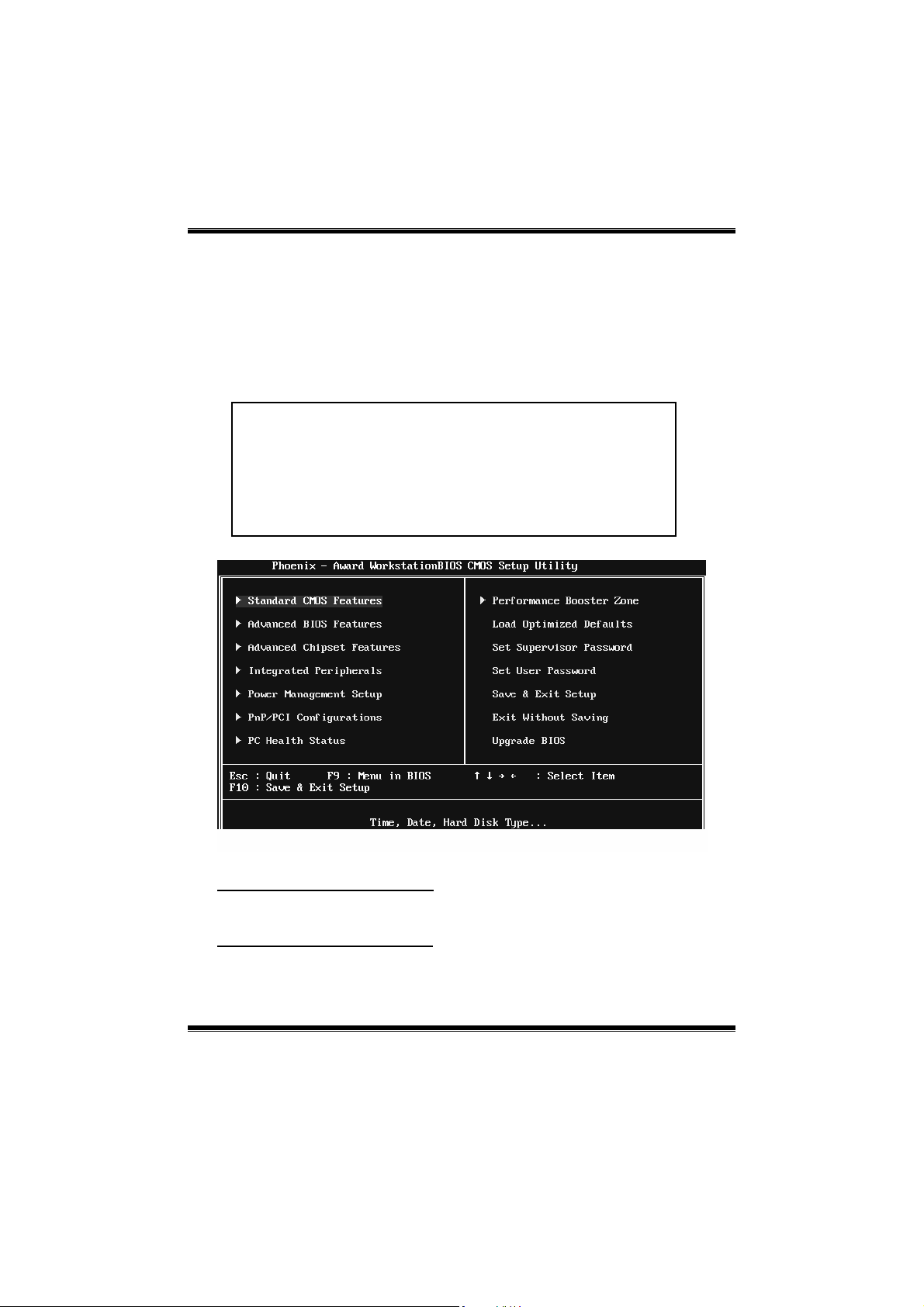
1 Main Menu
Onc e you enter Phoenix-Award BIOS™ CMOS Setup Utility, the Main Menu
will appear on t he screen. The Main Menu allows you to s elect from several
setup functions. Us e the arrow keys to select among the items and press <Enter>
to accept and enter the sub-menu.
!! WARNING !!
For better system performance, the BIOS firmware is being
continuously updated. The BIOS informatio n d escrib ed in
this manual (Figure 1, 2, 3, 4, 5, 6, 7, 8, 9) is for yo ur
reference only. The actual BIOS information and s ettings on
board may be slightly different from this manual.
Figure 1: Main Menu
Standar d CMOS Fe atures
This submenu contains industry standard configurable options.
Advanced BIOS Features
This submenu allo ws yo u to conf igur e advanc ed featur es of the BIOS.
4
Page 5
MCP6PB M2+/N68S BIOS Setup
Advanced Chipset Features
This submenu allows you to configure special chipset features.
Integrated Peripherals
This s ubmenu allows yo u to configure certain IDE hard drive options and
Programmed Input/ Output features.
Power Management Setup
This submenu allows you to configure the power management features.
PnP/PCI C onfigurations
This submenu allows you to configure certain “Plug and Play” and PCI options.
PC Health Status
This submenu allows yo u to monitor t he hardware of your system.
Performance Booster Zone
This submenu allows you to change CPU Vcore Voltage and CPU/PCI clock.
(However, we suggest you to use the default setting. Changing the voltage and
cloc k improperly may damage t he CPU or M/B!)
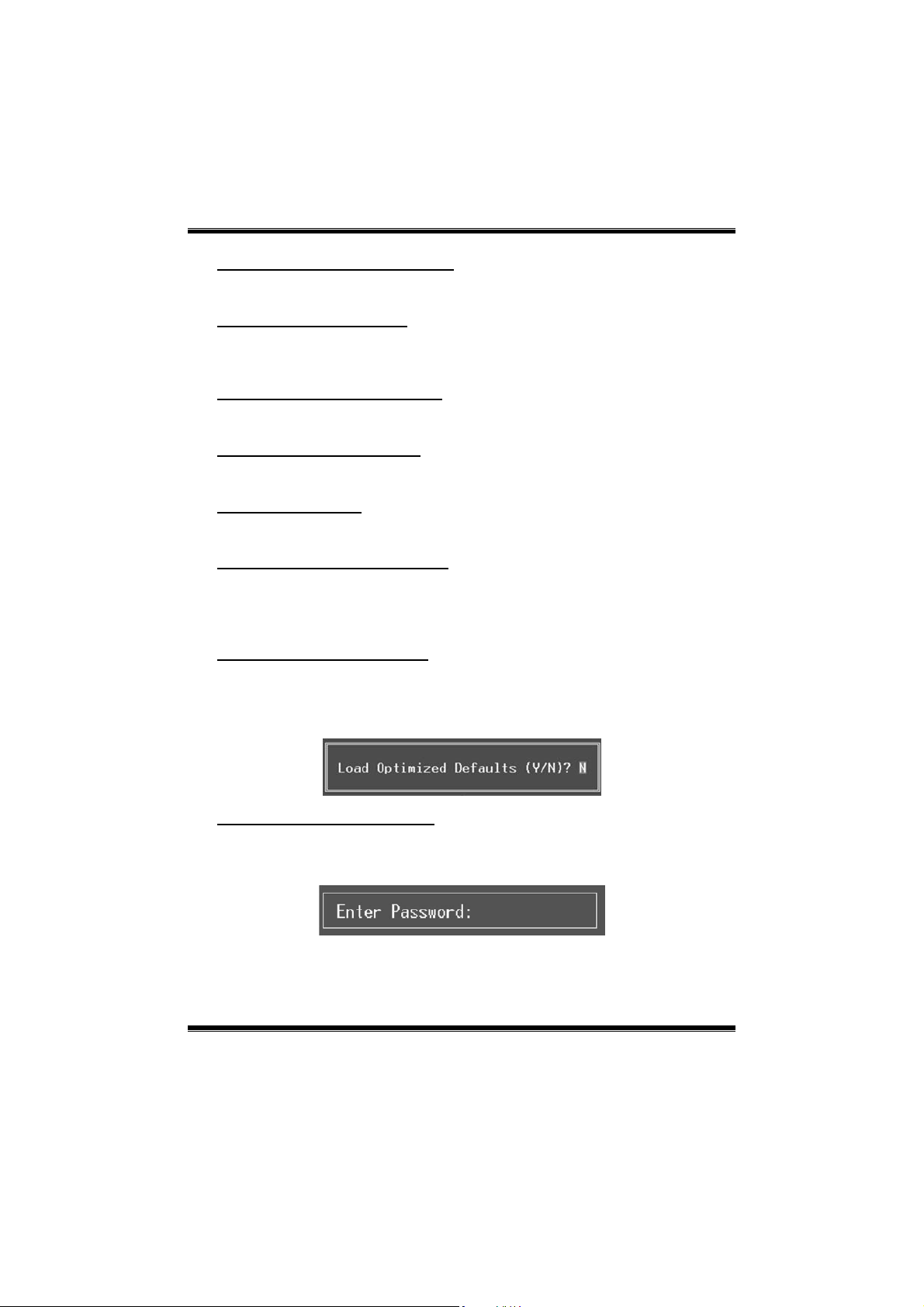
Load Opti mized Defaults
This selection allows you to relo ad the BIOS when problem occurs during
system booting sequenc e. These configurations are factory settings optimized
for this system. A confirmation message will be disp layed b efore defaults are
set.
Set Supervisor Password
Setting the supervisor pass wo rd will prohibit everyone exc ept the supervisor
from making c hanges us ing the C MOS Setup Utility. You will b e prompted with
to ent er a pass word.
5
Page 6
MCP6PB M2+/N68S BIOS Setup
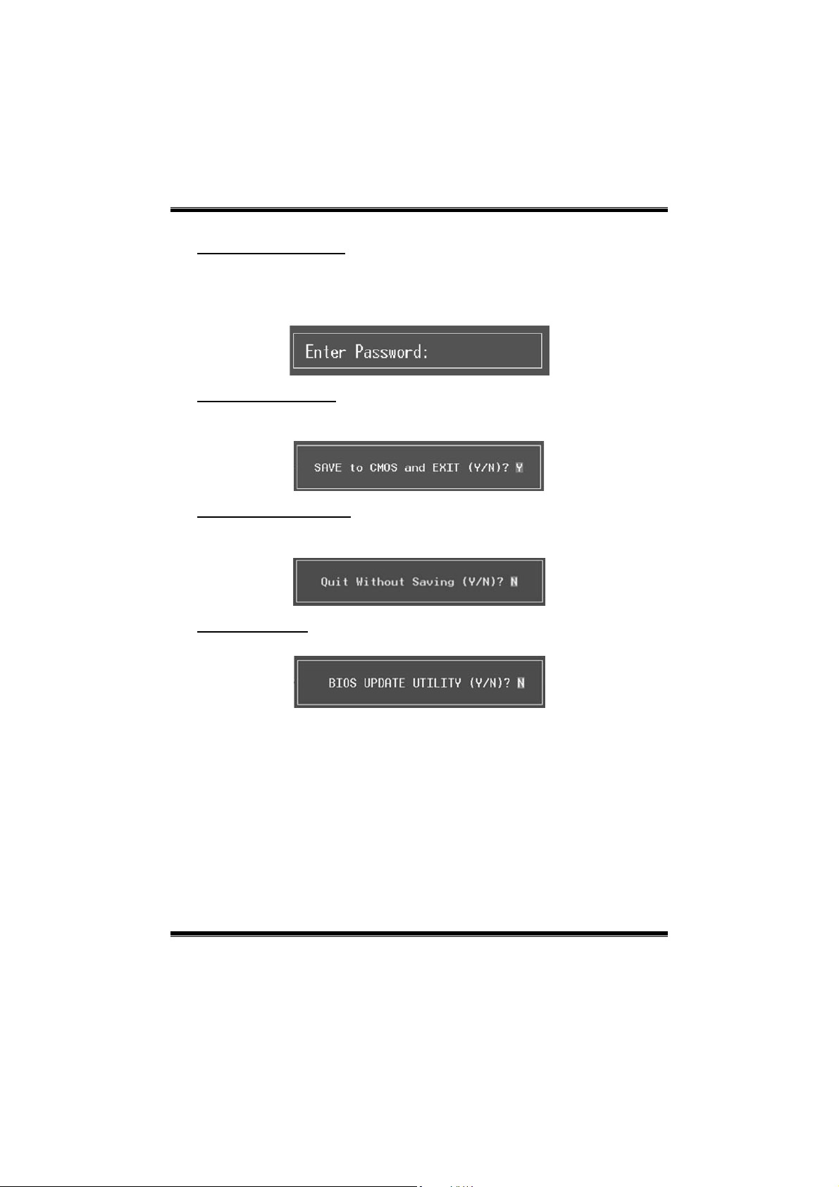
Set User Password
If the Supervisor P assword is not s et, then the User P assword will function in
the same way as the Supervisor Password. If the Supervisor Password is set and
the Us er Password is s et, the “User” will only be able to view configurations but
will not b e able to change them.
Save & Exit Setup
Save all configuration changes to CMOS (memory) and exit setup. Confirmation
message will be displayed before proceeding.
Exit Without Saving
Abandon all changes made during the current session and exit setup.
Confirmation message will be displayed before proceeding.
Upgrade BIOS
This submenu allows you to up grade bios.
6
Page 7
MCP6PB M2+/N68S BIOS Setup
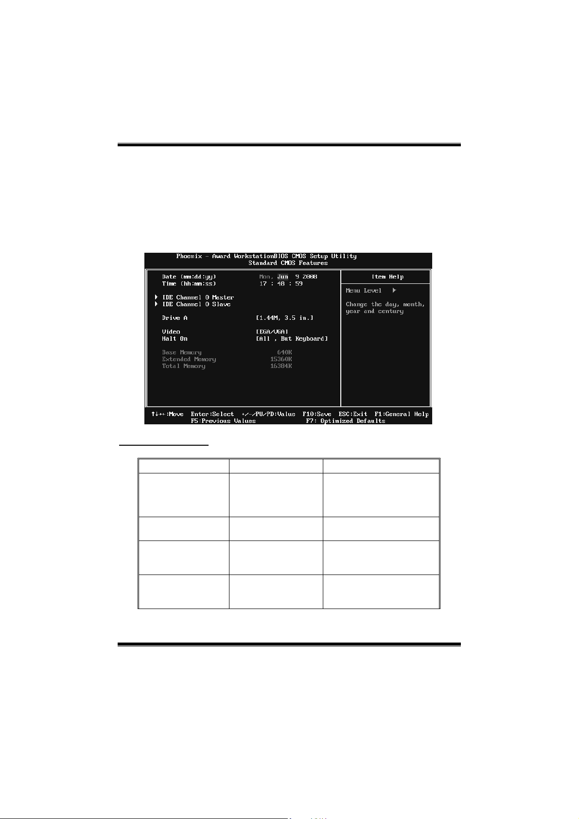
2 Standard CMOS Features
The items in Standard CMOS Setup Menu are divided into several categories.
Each category inc lud es no, on e or mo re than o ne setup items. Us e the arrow
keys to highlight the item and t hen use the<P gUp> or <PgDn> keys to se lect the
value you want in each item.
Figure 2: Standard CMOS Setup
Main Menu Selections
This table shows the items and the availab le options on the Main Menu.
Item Options Description
Date mm : dd : yy
Time hh : mm : ss
IDE Channel 0 Master
IDE Channel 0 Slave
Options are in its sub
Options are in its sub
menu.
menu.
Set the system date. Note
that the ‘Day’ automatically
changes when you set the
date.
Set the system internal
clock.
Press <Enter> to enter the
sub menu of detailed
options
Press <Enter> to enter the
sub menu of detailed
options.
7
Page 8

MCP6PB M2+/N68S BIOS Setup
Item Options Description
360K, 5.25 in
1.2M, 5.25 in
Drive A
Video
Halt On
Base Memory N/A
Extended Memory N/A
Total Memory N/A
720K, 3.5 in
1.44M, 3.5 in
2.88M, 3.5 in
None
EGA/ VG A
CGA 40
CGA 80
MONO
All Errors
No Errors
All, But Keyboard
All, But Diskette
All, But Disk/ Key
Select the type of floppy
disk drive installed in your
system.
Select the default video
device.
Select the situation in which
you want the BIOS to stop
the POST process and
notify you.
Displays the amount of
conventional memory
detected during boot up.
Displays the amount of
extended memory detected
during boot up.
Displays the total memory
available in the system.
8
Page 9
MCP6PB M2+/N68S BIOS Setup
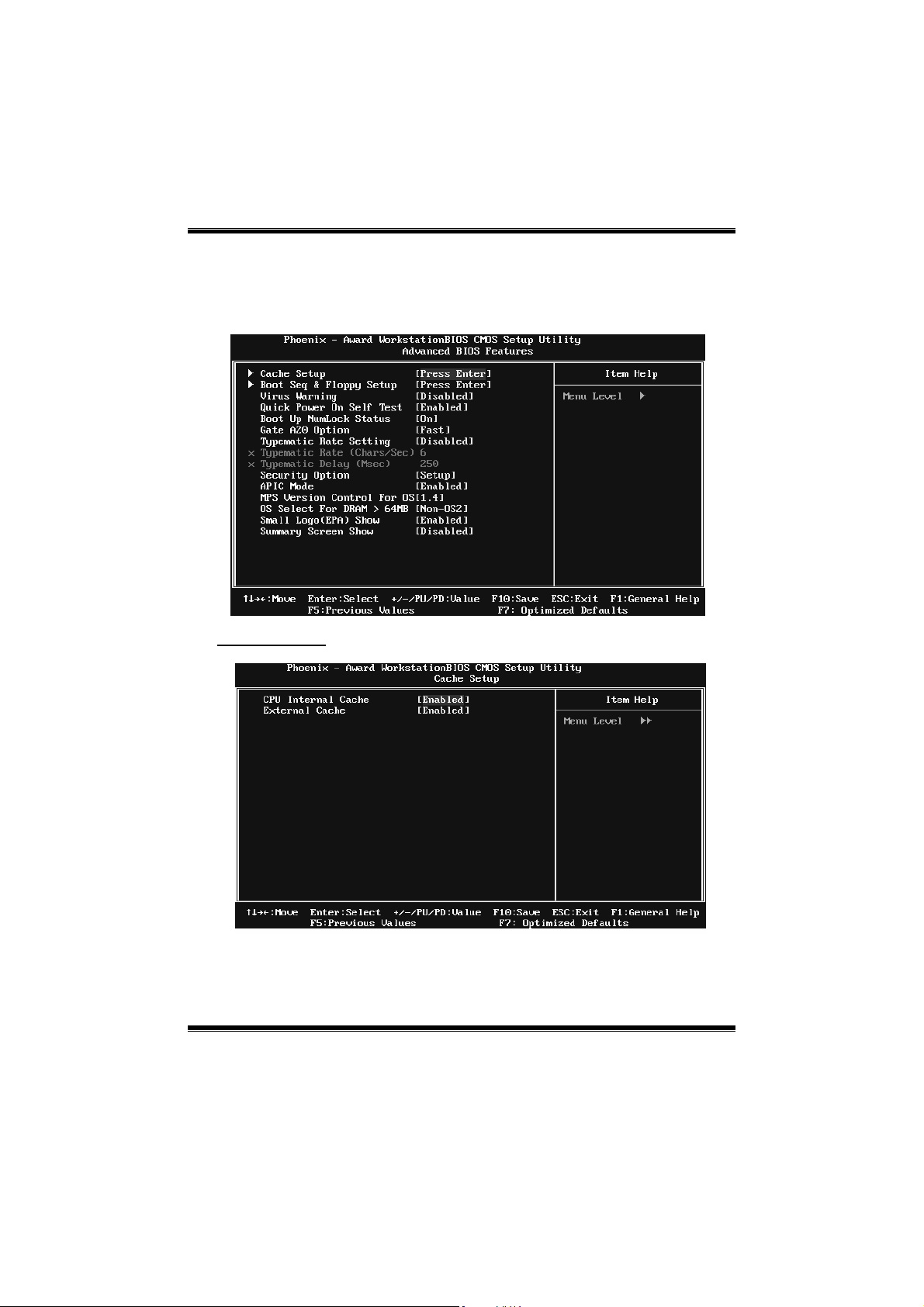
3 Advanced BIOS Features
Figure 3: Advanced BIOS Setup
Cache Setup
9
Page 10
MCP6PB M2+/N68S BIOS Setup
CPU Internal Cache
Depending on the CPU/chipset in use, you may be able to increase memory
ac ces s time with this optio n.
Enabled (default) Enable cache.
Disabled Disab le cache.
External Cache
This option enables or disables “Level 2” secondary cache on the CPU, which
may improve performance.
Enabled (default) Enable cache.
Disabled Disab le cache.
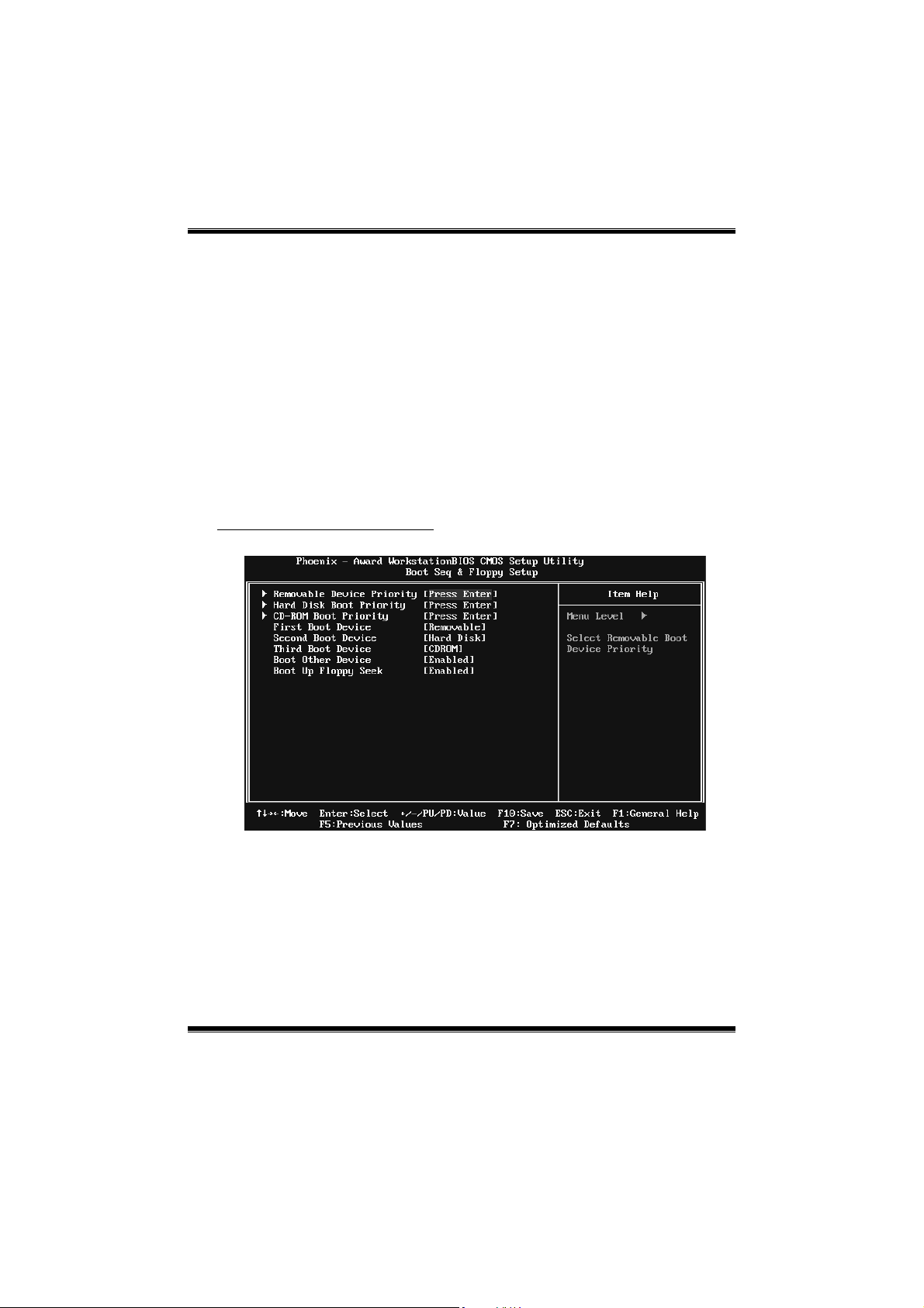
Boot Seq & Floppy Setup
This item allows you to setup boot sequence & Floppy.
10
Page 11
MCP6PB M2+/N68S BIOS Setup
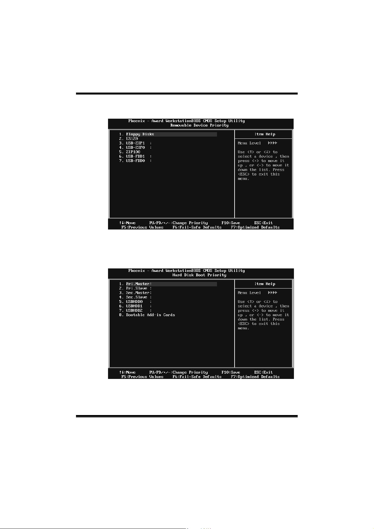
Removable Device Prior ity
Select Removable Boot Device Priority.
The Choices: Floppy Disks, Zip100, USB-F DD0 , US B-FD D1, USB-ZIP0,
USB-ZIP 1, LS 120.
Hard Disk Boot Priority
The BIOS will attempt to arrange the Hard Disk boot sequence
automatically.You can change the Hard Disk booting sequence here.
The Choices : Pri. Master, Pri. Slave, Sec. Master, Sec. Slave, USBHDD0,
USBHDD1, USBHDD2, and Bootable Add-in Cards.
11
Page 12
MCP6PB M2+/N68S BIOS Setup
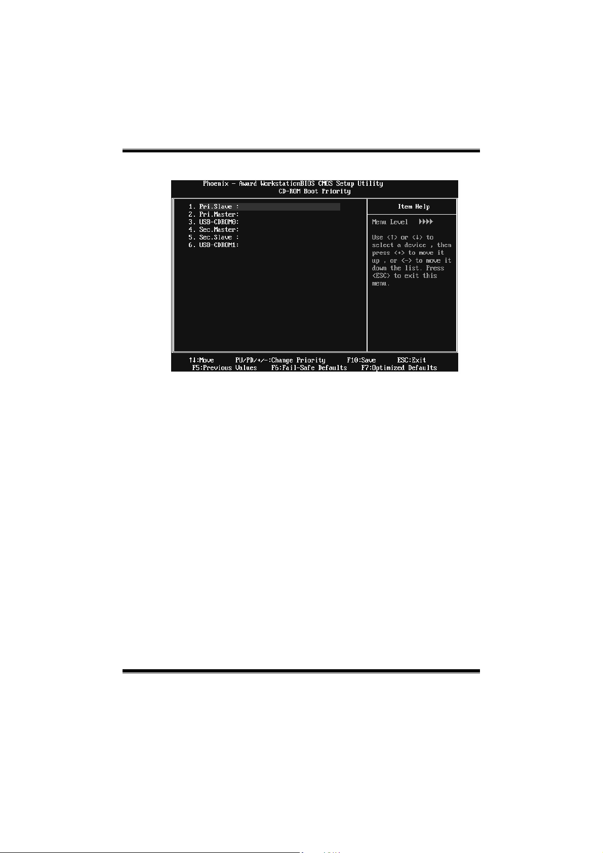
CD-ROM Boot Priority
The Choices: Pri. Master, Pri. Slave, Sec. Mas ter, Sec. S lave, USB-CDROM0,
USB-CDROM1.
First/Second /Third Boot Device
The BIOS will attempt to load the operating system in this order.
The Choices: Removable, Hard Disk, CDROM, Legacy LAN, Disabled.
Boot Other Device
When enabled, BIOS will try to load the operating system from other device
when it failed to load from the three devices above.
The Choices: Enabled (default), Disabled
Boot Up Floppy Seek
When enabled, System will test the floppy drives to determine if they have 40
or 80 tracks during boot up. Disabling this option reduces the time it takes to
boot-up.
The Choices: Enabled (default), Disabled.
12
Page 13

MCP6PB M2+/N68S BIOS Setup
Virus Warning
This option allows yo u to choose the VIRUS Warning feature that is us ed to
protect the IDE Hard Disk boot sector. If this function is enabled and an attempt
is made to write to the boot sector, BIOS will display a warning message on the
screen and sound an alarm beep.
Disabled (default) Virus protection is disabled.
Enabled Virus protectio n is activated.
Quick Power On Self Test
Enabling this option will cause an abridged version of the Power On Self-Test
(POS T) to ex ecute after yo u power up the co mpu ter.
Disabled Normal POST.
Ena bled (default) Enable quick POST.
Boot Up NumLock Status
Selec ts the NumLoc k St ate after t he syst em s witched o n.
The Choices:
On (def ault) Numpad is number keys.
Off Numpad is arrow keys.
Gate A20 Option
Select if chipset or keyboard controller should control Gate A20.
The Choices:
Normal A pin in the keyboard controller contro ls GateA20.
Fast (default) Lets chipset contro l Gate A20.
Typematic Rate Setting
When a key is held down, the keystroke will repeat at a rate determined by the
keyboard controller. When enabled, the typematic rate and typematic delay can
be configured.
The Choices: Disabled (d efault), Enabled.
Typematic Rate (Chars/Sec)
Sets the rate at whic h a keystroke is repe ated when yo u hold the key do wn.
The Choices: 6 (default), 8, 10, 12, 15, 20, 24, 30.
Typematic Delay (Msec)
Sets the delay time after the key is held down befo re it begins to repeat the
keystroke.
The Choices: 250 (default), 500, 750, 1000.
13
Page 14

MCP6PB M2+/N68S BIOS Setup
Security Option
This option will enable o nly individuals with p asswords to bring the system
online and/or to use the CMOS Setup Utility.
System: A pass word is required for the sys tem to boot and is also
req uired to access the Setup Utility.
Setup (default) : A pass word is required to access the S etup Utility only.
This will only apply if pass words are set from the Setup main menu.
APIC MODE
Selecting Enabled enables APIC device mode reporting from the BIOS to the
operating system.
The Choices: Enabled (default), Disabled.
MPS Version Control For OS
The BIOS supports version 1.1 and 1.4 of the Intel multiprocessor specification.
Selec t version s upported by t he operation system running on t his computer.
The Choices: 1.4 (default), 1.1.
OS Select For DRAM > 64MB
A c hoice other than Non-OS2 is only us ed for OS2 systems with memo ry
exceeding 64MB.
The Choices: Non-OS2 (d efault), OS2.
Small Logo(EPA) Show
This item allows yo u to selec t whether the “Small Logo” shows. Enabled
(default) “Small Logo” shows when system boots up. Disabled No “Small
Logo” shows when system boots
The Choices: Enabled (default), Disabled
Summary Screen Show
This item allows you to enable/disable the s ummary screen. S ummary screen
means system configuration and PCI device listing.
The Choices: Disabled (d efault), Enabled.
14
Page 15

MCP6PB M2+/N68S BIOS Setup
4 Advanced Chipset Features
This submenu allo ws yo u to configure the specific features of the chipset
installed on your system. This chipset manage bus speeds and access to system
memory resources, such as DRAM. It also coordinates communications with the
PCI bus. The default settings that came with your system have been optimized
and t herefore should no t be changed unless you are susp icious that the set tings
have been changed incorrectly.
Figure 4: Advanced Chipset Setup
Frame Buffer Size
This item allows you to choose the frame buffer size of on-chip VGA.
The Choices: 128MB (default), 16MB, 32MB, 64MB, 256MB, Disabled.
GPU Bank Flip
The Choices: Disabled (d efault), Enabled.
PCIE / SATA Spread Spectrum
This item allows you to enab le/disable the Spread Spectrum function.
The Choices: Disabled (default), Triangular Down.
15
Page 16

MCP6PB M2+/N68S BIOS Setup
HT Spread Spectrum
This item allo ws you to select HT Sp read Spectrum function.
The choices: Disa bled (default), 0.50% H.Kiss Cntr
SSE/SSE2 instruction
This item allo ws you to enab le/disable SSE/SS E2 ins truction.
The Choices: Enabled (default), Disabled.
CPU Feature
Virtualiza tion
Virtualization Technology can virtually separate your system resource into
several parts, thus enhance the performance when running virtual machines or
mult i interface syst em s.
The Choices: Enabled (default), Disabled.
AMD K8 Coo l&Quiet control
The item allows you select K8 Cool’n’Quiet control.
The Choices: Auto (default), Disabled.
16
Page 17

MCP6PB M2+/N68S BIOS Setup
System BIOS Cacheable
Selec ting t he “Enabled” option allo ws c aching of the system BIOS ROM at
F0000h-FFFFFh, which is able to improve the system performance. However,
any programs that attempts to write to this memory block will cause conflicts
and result in s ystem errors.
The Choices: Disabled (d efault), Enabled.
17
Page 18

MCP6PB M2+/N68S BIOS Setup
5 Integrated Peripherals
Figure 5. Integrated Peripherals
IDE Function Setup
18
Page 19

MCP6PB M2+/N68S BIOS Setup
RAID Config
RAID Enable
This option allows you to enable or disable RAID function.
The Choices: Disabled (default), Enabled.
SATA 1/2 Prim ary /Secondary RAID
This option allows you to enable or disable SATA Primary/Secondary RAID.
The Choices: Disabled (default), Enabled.
On-chip IDE Cha nne l 0
The motherboard chipset contains a PCI IDE interface with support for two
IDE channels. Select “Enabled” to activate the first and/or second IDE interface.
Select “Disabled” to deactivate an interface if you are going to install a primary
and/or secondary add-in IDE interface.
The Choices: Enabled (default), Disabled.
Primary Mas ter/Slave PIO
The IDE PIO (P rogrammed Input / Output) fields let you set a PIO mode (0-4)
for each of the IDE devices that the onboard IDE interface supports. Modes 0
to 4 will increase performance progressive ly. In Auto mode, the system
automatically determines the best mode for each device.
The Choices: Auto (default), Mode0, Mode1, Mode2, Mode3, Mode4.
19
Page 20

MCP6PB M2+/N68S BIOS Setup
Primary Mas ter/Slave UDMA
Ultra DMA function can be implemented if it is supported by the IDE hard
drives in your system. As well, your operating environment requires a DMA
driver (Windows 95 or OSR2may need a third party IDE bus master driver). If
your hard drive and your system software both support Ultra DMA, select Auto
to enable BIOS support.
The Choices: Auto (default), Disabled.
IDE DMA Transfer Access
This item allows you to enable or disable the IDE DMA transfer access.
The Choices: Enabled (default), Disabled.
Serial-AT A Controller
Enables support for Serial-ATA controller.
The Choices: All Enabled (default), Disabled
IDE Prefetch Mode
The “onboard” IDE drive interfaces supports IDE prefetch function for faster
drive access. If the interface on your drive does not support prefetching, or if
you install a primary and/or secondary add-in IDE interface, set this option to
“Disabled”.
The Choices: Enabled (default), Disabled.
20
Page 21

MCP6PB M2+/N68S BIOS Setup
Onboard Device
USB Keyboard/ Storage Suppor t
This item allows you to support the USB legacy devices.
The Choices: Enabled, Disabled (default).
USB Mouse Support
This item allows you to enable or disable the USB Mouse Legacy Support.
Enabled Enable USB Mouse Support.
Disabled (default) Disab le USB Mouse Support.
HD Audio
This item allows you to enable or disable to support HD Audio.
The Choices: Auto (default), Disabled.
MAC LAN
This option allows you to control the onboard MAC LAN.
The Choices: Auto (default), Disabled.
21
Page 22

MCP6PB M2+/N68S BIOS Setup
MAC Media Interface
This option allows you to control the onboard MAC Media Interface.
The Choices: Pin Strap (default), MII, RGMII
Onboard LAN Boot ROM
This item allows you to enable or disable the Onboard LAN Boot ROM.
The Choices: Disabled (default), Enabled.
Onboard I/O Address
Onboard FDC Controller
Select enabled if your system has a floppy disk controller (FDC) installed on
the system board and you wish to use it. If you installed another FDC or the
system uses no floppy drive, select disab led in this field.
The Choices: Enabled (default), Disabled.
22
Page 23

MCP6PB M2+/N68S BIOS Setup
Onboard Serial Port 1
Select an address and corresponding interrupt for the first and second serial
ports.
The Choices: 3F8/IRQ4 (default), Disabled, 2F8/IRQ3, 3E8/IRQ4, 2E8/IRQ3,
Auto.
Onboard Para llel Port
This item allows you to determine access onboard parallel port controller with
which I/O Address.
The Choices: 378/IRQ7 (default), 278/IRQ5, 3BC/IRQ7, Disabled.
Parallel Port Mode
This item allows you to determine how the paralle l port should function. The
default value is SPP.
The Choices:
SPP (def au lt) Using Parallel po rt as Standard Prin te r Port.
EPP Usin g P arallel Port a s En hanced P ar allel Port.
ECP U sin g Pa rallel port a s Ext end ed Capabilit ies P ort.
ECP+ EPP Usin g P arallel port as ECP & EPP mode.
ECP Mode Use DMA
Onboard GPU
This item allows you to control the Onbo ard GPU.
The Choices: Auto (default), Always Enable.
OnChip USB
This optio n s hould be enabled if your s ystem has a USB ins talled o n the system
board. You may need to disable this feature if you add a higher performance
controller.
The Choices: V1.1+V2.0 (default), Disabled, V1.1
Select a DMA Channel for the port.
The Choices: 3 (default), 1.
23
Page 24

MCP6PB M2+/N68S BIOS Setup
IDE HDD Block Mode
Block mode is also called block transfer, multiple co mmands, or mult iple
sectors read / write. If your IDE hard drive supports block mode (most new
drives do), select Enabled for automatic detection of the optima l number of
block mod e (most n ew drives do), select Enab led for automatic detectio n of the
optimal number of block read / write per sector where the drive can support.
The Choices: Enabled (default), Disabled.
24
Page 25

MCP6PB M2+/N68S BIOS Setup
6 Power Management Setup
The Power Management Setup Menu allows you to configure yo ur system to
utilize energy conservation and power up/power down features.
Figure 6. Power Manageme nt Se tup
ACPI Function
This item displa ys the status of the Ad vanc ed Configuration and Power
Management (ACPI).
The Choices: Enabled (default), Disabled.
ACPI Suspend Type
The item allo ws you to s elect the susp end typ e under the ACP I op erating
system.
The Choices: S1 (POS) (default) Power on Suspend
S3 (STR) Suspend to RAM
S1 & S3 POS+STR
25
Page 26

MCP6PB M2+/N68S BIOS Setup
Power Management
This c ategory allows you to select the po wer saving method and is directly
rela ted to the fo llowin g mod es :
1. HDD P o wer Do wn.
2. Suspend Mode.
There are three options of Power Management, three of which have fixed mode
settings
Min. Power Saving
Minimum po wer management.
Suspend Mode = 1 hr.
HDD Power Down = 15 min
Max. Power Saving
Maximum power management only available for sl CPU’s.
Suspend Mode = 1 min.
HDD Power Down = 1 min.
Use r De f ine (default)
Allow yo u to set each option individually.
When you choose user define, you ca n adjust each of the item from 1 min. to 1
hr. except for HDD Power Down which ranges from 1 min. to 15 min.
Video Off Method
This option determines the manner when the monitor goes blank.
V/H SYNC+Blank
This selection will c ause the system to turn off the vertical and horizontal
synchronization ports and write blanks to the video buffer.
Blank Screen
This option o nly writes blanks to the video b uffer.
DPM S Suppo rt
Initial display power management signaling.
HDD Power Dow n
When enabled, the hard-dis k drives will power down after a set time of system
inactivity. All other devices remain active.
The Choices: Disabled (d efault), 1 Min, 2 Min, 3 Min, 4 Min, 5 Min, 6 Min, 7
Min, 8 Min, 9 Min, 10 Min, 11 Min, 12 Min, 13 Min, 14 Min, 15 Min.
(default)
26
Page 27

MCP6PB M2+/N68S BIOS Setup
Soft-Off by PBTN
This item determines t he behavior of sys tem power butto n. Instant off turn off
the po wer immediately, and Delay 4 Sec. will require you to press and hold the
power button for 4 seconds to cut off t he sys tem po wer.
The Choices: Delay 4 Sec, Instant-Off (default).
WOL(PME#)/ From Soft-Off
This item allows yo u to enable or disable Wake On LAN from Soft-Off
function.
The Choices: Disabled (d efault), Enabled.
WOR(R I#) From Soft-Off
This item allows you to enab le o r d isable Wake On Ring fro m Soft-Off function.
The Choices: Disabled (d efault), Enabled.
USB Resume from S3/S4
This item allows you to enab le or d isabled the USB devic e wake up from S3 /S4
function.
The Choices: Disabled (default), Enabled.
S5 Resume by USB
The Choices: Disabled (default), Enabled.
Power-On by Alarm
This function is for setting date and time for yo ur computer to boot up. When
enabled, you ca n choose the date and time to boot up the system.
The Choices: Disabled (d efault), Enabled.
Date (of Month) Alarm
You c an c hoos e which month t he system wil l boot up.
Time (hh:mm:ss) Alarm
You can choose the s ystem boot up time, input hour, minute and second to
specify.
Note: If you have change the setting, you must let the sys tem boo t up until it
goes to the op erating s ystem, before this func tion will work.
27
Page 28

MCP6PB M2+/N68S BIOS Setup
HPET Support
This item allows you to control the high precis ion event timer.
The Choices: Enabled (default), Disabled.
POWER ON Function
This item allows you to choose the power on method.
The Choices: Button Only (default), Password, Hot Key, Mouse Move/Click,
Mouse Double Click, Any Key, Keyboard 98.
KB Power ON Password
Input password and press Enter to set the Keyboard power on password.
Hot Key Power ON
Choos e the Hot Key comb ination to boot up the s ystem.
The Choices: Ctrl-F1 (default), Ctrl-F2, Ctrl-F3, Ctrl-F4, Ctrl-F5, Ctrl-F6,
Ctrl-F7, Ctrl-F8, Ctrl-F9, Ctrl-F10, Ctrl-F11, and Ctrl-F12.
PWRON After PWR-Fail
This s etting spec ifies how yo ur system should behave after a po wer fail or
interrupts occurs. By choos ing o ff will leave the co mputer in the power off state.
Choosing On will reboot the computer. Former-Sts will restore the s ystem to the
status befo re po wer failure or interrupt occ urs.
The Choices: Off (default), On, Former-S ts.
28
Page 29

MCP6PB M2+/N68S BIOS Setup
7 PnP/PCI Configurations
This section describes configuring the PCI bus system. PCI, or Personal
Computer Interconnect, is a system which allows I/O devices to operate at
speeds nearing the speed of the CPU itself uses when communicating with its
own special components. This s ectio n covers some ver y technical items and it is
strongly recommended that only experienced users should make any changes to
the default settings.
Figure 7: PnP/PCI Configurations
Init Display First
With systems that have multip le video cards, this item d etermines whether the
primary display uses a PCI Slot or an AGP Slot.
The Choices: PCIEx (default), PCI Slot, Onboard.
29
Page 30

MCP6PB M2+/N68S BIOS Setup
Reset Configuration Data
The s ystem BIOS s uppo rts the P nP f eature which requires the system to record
whic h res ources are ass igned and protects resourc es from conflict.
Every peripheral device has a node, which is c alled ESCD. T his node records
whic h resourc es are as signed to it. The s ystem needs to rec ord and update ES CD
to the memory locations. These locations are res erved in the system BIOS. If the
Disabled (default) option is chosen, the system‘s ESCD will update only when
the new c onfiguration varies f rom t he las t o ne. If the Enab led opt ion is chos en,
the system is forced to update ESCDs and then is auto matically set to the
“Disabled” mode.
The above s ett ings will be s hown o n the screen only if “Manual” is chosen for
the resourc es controlled by function.
Legacy is the term, which signifies that a resource is assigned to the IS A Bus
and p rovides non-PnP ISA add -o n ca rds. PCI / IS A PnP s ignify t hat a r esource
is assigned to the PCI Bus or provides for ISA PnP add-on cards and
peripherals.
The Choices: Disabled (d efault), Enabled.
Resources Controlled By
By Choos ing “Auto(ESCD)” (default), the system BIOS will detect the system
resources and automatically assign the relative IRQ and DMA channel for each
peripheral. By Choosing “Manual”, the user will need to assign IRQ & DMA for
add-on cards. Be sure that there are no IRQ/DMA and I/O port conflicts.
The Choices: Auto (ESCD) (default), Manual.
IRQ Resources
This sub menu will allo w you to assign each sys tem interrupt a typ e, depending
on the type of device using the interrupt. When you press the “Press Enter” tag,
you will be direc ted to a submenu that will allow you to configure the system
interrupts. This is only configurable when “Resourc es Controlled By” is set to
“Manual”.
IRQ-5 ass igned to PCI Device
IRQ-7 ass igned to PCI Device
IRQ-9 ass igned to PCI Device
IRQ-10 ass igned to PCI Device
IRQ-11 ass igned to PCI Device
IRQ-14 ass igned to PCI Device
IRQ-15 ass igned to PCI Device
30
Page 31

MCP6PB M2+/N68S BIOS Setup
PCI / VGA Palette Snoop
Some old graphic controllers need to “snoop” on the VGA palette and then map
it to their display as a way to pro vide boo t information and VGA compatibility.
This item allo ws such snoop ing to take place.
The Choices: Disabled (d efault), Enabled.
Ma xi mu m Payload Siz e
Set t he maximum payload size fo r Transac tio n pac kets (TLP).
The Choice: 4096 (default.), 128, 256, 512, 1024, 2048.
31
Page 32

MCP6PB M2+/N68S BIOS Setup
8 PC Health Status
Figure 8: PC Health Status
Smart Fan Option
32
Page 33

MCP6PB M2+/N68S BIOS Setup
CPU Smart Fan
Smar t Fan Calibration
PWM Du ty Off<℃>
PWM Duty Start<℃>
Start PWM Value
Smart Fan Slope
T his item allows you to contro l the CP U Fan .
The Choices: Disabled (default), Auto, 4-pin, 3-pin..
Choose this item and then the BIOS will auto test and detect the CPU fan
functions and show CPU fan speed.
If the CPU Temperature is lower than the set value, FAN will turn off.
The Choices: Min=0,.Max=127, Key in a DEC number.
CPU fan starts to work under smart fan function when arrive this set
value.
The Choices: Min=0,.Max=127, Key in a DEC number.
Whe n CPU temper atu re arr ives to the set va lue, the CPU fan will wo rk
under Smart Fan F unc tio n mod e. The range is from 0~127, with an
interval of 1.
The Choices: Min=0,.Max=127, Key in a DEC number.
Increasing the value o f slop e PWM will raise the speed of CPU fan.
The Choices: Min=1,.Max=127, Key in a DEC number.
Shutdown Temperature
This item allo ws you to set up the CP U shutdown Temperature. This item is
only effective under W indows 98 ACPI mode.
The Choices: Disabled (default), 60℃/ 140℉, 65℃/ 149℉, 7 0℃/ 158℉, 75℃
/ 167℉, 80℃/ 176℉, 85℃/ 185℉, 90℃/ 167℉.
Show H/W Monitor in POST
If you co mputer c ont ains a monitoring system, it will s how PC health status
during POST stage. The item offers several different delay times.
The Choices: Enabled (default), Disabled.
CPU Vcore, Chipset Volt, +3.3V, +5.0V, +12.0V, DDR/HT
Voltage, 5V (SB), Voltage Battery
Detect the sys tem’s voltage status automatic ally.
33
Page 34

MCP6PB M2+/N68S BIOS Setup
CPU Temp
This field displays the current temperature of CPU.
Current CPU FAN Speed
This field displays the curren t speed of C P U fan.
Current SYS FAN Speed
This field dis plays the current sp eed S YSTEM fan.
34
Page 35

MCP6PB M2+/N68S BIOS Setup
9 Performance Booster Zone
Fig ure 9: Performance Booster Zone
CPU VID Control
This func tion allows you to ad just the CPU voltage.
The Choices: Default (default), +3.3%, +6.6%, +10%.
CHIP VID Control
This function allows you to adjust the chipset voltage.
The Choices: Default (default), +0.04, +0.08, +0.12
HT Voltage Control
This function allows yo u to adjust the HT vo ltage.
The Choices: Default (default), +0.02V, +0.04V, +0. 06V.
NPT Vid control
This func tion allows you to ad just the FSB voltage.
The Choices: Auto (default), 0.3875v ~ 1.550v
35
Page 36

MCP6PB M2+/N68S BIOS Setup
Memory Voltage
This item allo ws you to select memory Vo ltage.
The Choices: 1.950V (default), 2.000V, 2.050V, 2.100V, 2.150V, 2.200V,
2.250V, 2.300V
NPT Fid control
This function a llows you to adjust the ratio frequency.
The Choices: Auto (default), x4 800Mhz ~ x24.5 4900Mhz
CPU Frequency
This item allo ws you to select the CPU Frequency.
The Choices: 200.0 (default), 201.0~450.0.
PCIE Clock
The Choices: 100MHz (default), 101MHz ~ 150MHz
K8<->NB HT Speed
This item allo ws you to select the K8<->NB HT Sp eed.
The Choices: Auto (default), 1x, 2x, 3x, 4x, 5x.
K8<->NB HT Width
This item allo ws you to select the K8<->NB HT width.
The Choices: Auto (default), ↓8↑8, ↓16↑ 16.
36
Page 37

MCP6PB M2+/N68S BIOS Setup
DRAM Configuration
Timing Mode
The Choices: Auto ( def ault), MaxM emClk, Manual.
Memory Clock value or Limit
The Choices: DDR 400 (default), DDR 533, DDR 667, DDR 800.
DCTs Mode
This item controls the DRAM controller ganged (128bit*1) / unganged
(64bit*2) dual-channel operation mode. If two DRAM modules with d ifferent
size are installed, using ungan ged mode can still make it run in dual-channel
operation.
T he Choices : Ungan ged (def ault), Gange d.
CKE bas e power dow n mode
The Choices: Enabled (default), Disabled.
CKE base powerdown
The Choices: Per Channel (default), Per CS.
Memclock tri-stating
The Choices: Disabled (default), Enabled.
37
Page 38

MCP6PB M2+/N68S BIOS Setup
Memory Hole Remapp ing
The Choices: Enabled (default), Disabled.
Auto Optimize Bottom IO
The Choices: Enabled (default), Disabled.
Bottom of [31:24] IO space
The Choices: Min=0000 Max=00FF; Key in a HEX number.
Botto m of UM A D RAM [31:24]
The Choices: Min=0000 Max=00FC; Key in a HEX number.
DDRII Timing Item
The Choices: Disabled (default), Enabled.
TwTr Command Delay
The Choices: 3 bus clocks (default), 1 bus clocks, 2 bus clocks.
Trfc0 for DIMM0
The Choices: 75ns (default), 105ns, 127.5ns, 195ns, 327.5ns.
Trfc1 for DIMM1
The Choices: 75ns (default) , 105ns, 127.5ns, 195ns, 327.5ns.
<Twr> Write Recovery Time
The Choices: 6 bus clocks (default), 3 bus clocks, 4 bus clocks, 5 bus clocks.
<Trtp> Precharge Time
The Choices: 3 clocks (default), 2 clocks.
<Trc> Row Cycle Time
The Choices: 26 bus clocks (default), 11-25 bus clocks.
<Trcd> RAS to CAS R/W Delay
The Choices: 6 clocks (default), 3 clocks, 4 clocks, 5 clocks.
<Trrd> RAS to RAS Delay
The Choices: 5 clocks (default), 2 clocks, 3 clocks, 4 clocks.
38
Page 39

MCP6PB M2+/N68S BIOS Setup
<Trp> Row Prech arge Time
The Choices: 6 clocks (default), 3 clocks, 4 clocks, 5 clocks.
<Tras> Minimum RAS Active T
The Choices: 18 bus clocks (default), 5-17 bus clocks.
Special Notice:
If the system’s fr equenc y that yo u are select ed is not funct ioning, there are t wo methods
of booting-up the system.
Method 1:
Clear the CMOS data by s etting the JCMO S1 ((2-3) closed)) as “ON” status. All t he
CMOS data will b e loaded as defaults setting.
Method 2:
Press the <Insert> key and Power button simultaneous ly, afte r that keep-on press ing t he
<Ins ert> key until the power-on screen showed.
This action will boot-up the system according to FSB of the processor
It’s strongly reco mmended to set CPU Vcore and clock in default s etting. If the CPU
Vcore and clock are not in default setting, it may cause CPU or M/B damage.
39
 Loading...