

BIO RAD PowerPac HV Instruction Manual

PowerPac
™
HV
Power Supply
Instruction Manual
Catalog Numbers
164-5056
and
164-5059


Technical Support
For Technical Support contact your local Bio-Rad office. In the US call 1-800-424-6723.
Please have the following information available.
Model number: Located on the sticker on the bottom of the unit.
Serial number: Located on the sticker on the bottom of the unit.
Firmware version: The PowerPac HV displays the software version momentarily after
switching the power ON.
State clearly the error code, error message or anomaly, and the conditions that originated
the problem, including run parameters (volts, amperes and watts) as well as electrophoresis
cell and buffer system.
Calibration and Service agreements are available through Technical Support.
© 2013 Bio-Rad Laboratories, Inc. All rights reserved.
Palm is a trademark of Palm Source, Inc.
Windows 2000 and Windows XP are trademarks of Microsoft Corp.


Safety
!
!
Read this page before proceeding.
Bio-Rad PowerPac power supplies are designed and certified to meet EN 61010* safety
standards. Certified products are safe to use when operated in accordance with the
instruction manual. This safety certification does not extend to electrophoresis cells or
accessories that are not EN 61010 certified, even when connected to this power supply.
This instrument should not be modified or altered in any way. Alteration of this instrument will
void the manufacturer's warranty, void the EN 61010 certification, and create a potential
safety hazard for the user.
This product is intended for laboratory use only. It is not intended for use in residential or
commercial environments. Bio-Rad is not responsible for any injury or damage caused by the
use of this instrument for purposes other than those for which it is intended, or by modifications
of the instrument not performed by Bio-Rad or an authorized agent.
PowerPac power supplies use high output voltages that are electrically grounded to minimize
the risk of electrical shock. PowerPac power supplies have passed tests for operation at
temperatures between 0° and 40°C, with relative humidity between 0 and 95%,
non-condensing. Operating the power supply outside these conditions is not recommended
by Bio-Rad and will void the warranty.
The following guidelines should be observed and followed.
1. Do not block the fan vents at the rear of the unit. There must be at least 6 cm
clearance around the power supply during operation.
2. The power supply must be kept away from wet surfaces. Avoid splashing or leaking
solutions into the power supply.
3. Always connect the power supply to a grounded AC outlet. An acceptable power cord
is provided with the instrument.
4. Bio-Rad electrophoresis cells have molded two-prong plugs that are inserted into the
power supply's high voltage output jacks. These plugs have been EN 61010 certified
for safety compliance for use with PowerPac power supplies. Use of other plugs or
banana jacks is done at the user's own risk and is not recommended by Bio-Rad.
When inserting and removing the molded two-prong plug, always grasp the plug by the
molded support at the rear of the plug. Do not grasp the individual prong ends.
5. Do not operate the power supply in extreme humidity (>95%) or where condensation
can short the internal electrical circuits of the power supply.
6. When taking the power supply from room temperature into a cold room, the unit can be
operated immediately. When removing the power supply from a cold room, the unit
must be at room temperature for a minimum of 2 hours before operation.
7. Never connect a high-voltage output lead to earth ground. This cancels the floating
ground of the power supply and exposes the user to potentially lethal high voltages.
Caution
This product conforms to the Class A Standards for electromagnetic emissions, intended
for laboratory equipment applications. It is possible that emissions from this product may
interfere with some sensitive appliances when placed near or on the same circuit. The user
should be aware of this potential and take appropriate measures to avoid interference.
*The EN 61010 is an internationally accepted electrical safety standard for laboratory instruments.


Table of Contents
Page
Section 1 Introduction ................................................................................1
1.1 Overview.................................................................................................1
1.2 Features .................................................................................................2
1.3 Unpacking...............................................................................................3
Section 2 Control Panel..............................................................................4
Section 3 Product Setup.............................................................................5
3.1 Power Supply Connections.....................................................................5
3.2 Preferences Setup..................................................................................6
3.3 Explanation of Safety Features and Setup Options .................................7
3.3.1 Pfd: Power Failure Detection .....................................................7
3.3.2 RRCd: Rapid Resistance Change Detection..............................8
3.3.3 NLd: No Load Detection ............................................................8
Section 4 Operation ..................................................................................10
4.1 Manual Mode........................................................................................11
4.1.1 Create, Edit and Run in Manual Mode .....................................12
4.2 Basic Methods Mode ............................................................................14
4.2.1 Create, Edit and Run a Basic Method ......................................15
4.3 IEF Methods Mode ...............................................................................18
4.3.1 Create, Edit and Run an IEF Method .......................................19
4.4 Temperature Mode ...............................................................................22
4.4.1 Create, Edit and Run in Temperature Method..........................23
4.5 Edit a Paused Run................................................................................25
4.5.1 Editing a Paused Run ..............................................................26
Section 5 Data Transfer Using the Infrared (IR) Port...............................27
5.1 Overview...............................................................................................27
5.2 System Requirements...........................................................................28
Section 6 Maintenance and Troubleshooting..........................................29
6.1 Maintenance .........................................................................................29
6.1.1 Replacing a Fuse.....................................................................29
6.1.2 Replacement Parts ..................................................................30
6.2 Troubleshooting ....................................................................................30
6.3 Error Messages ....................................................................................31
Appendix A Technical Specifications ..........................................................34
Appendix B Warranty and Ordering Information ........................................35

List of Figures
Figure 1. Front View................................................................................................1
Figure 2. Rear View ................................................................................................1
Figure 3. Front Panel with Legs ..............................................................................2
Figure 4. Front Panel ..............................................................................................4
Figure 5. Power Leads Connected Correctly ..........................................................5
Figure 6. Power Leads Connected Incorrectly ........................................................5
Figure 7. Menu Overview for Manual Operation ....................................................11
Figure 8. Menu Overview for Basic Methods Mode ..............................................14
Figure 9. Menu Overview for IEF Methods ............................................................18
Figure 10. Menu Overview for Temperature Mode ..................................................22
Figure 11. Menu Overview for Editing a Pause Run ................................................25
Figure 12. IR Port Location ....................................................................................27
Figure 13. Transfer of Methods and Run Data Files ................................................27
Figure 14. Location of Fuse ....................................................................................29
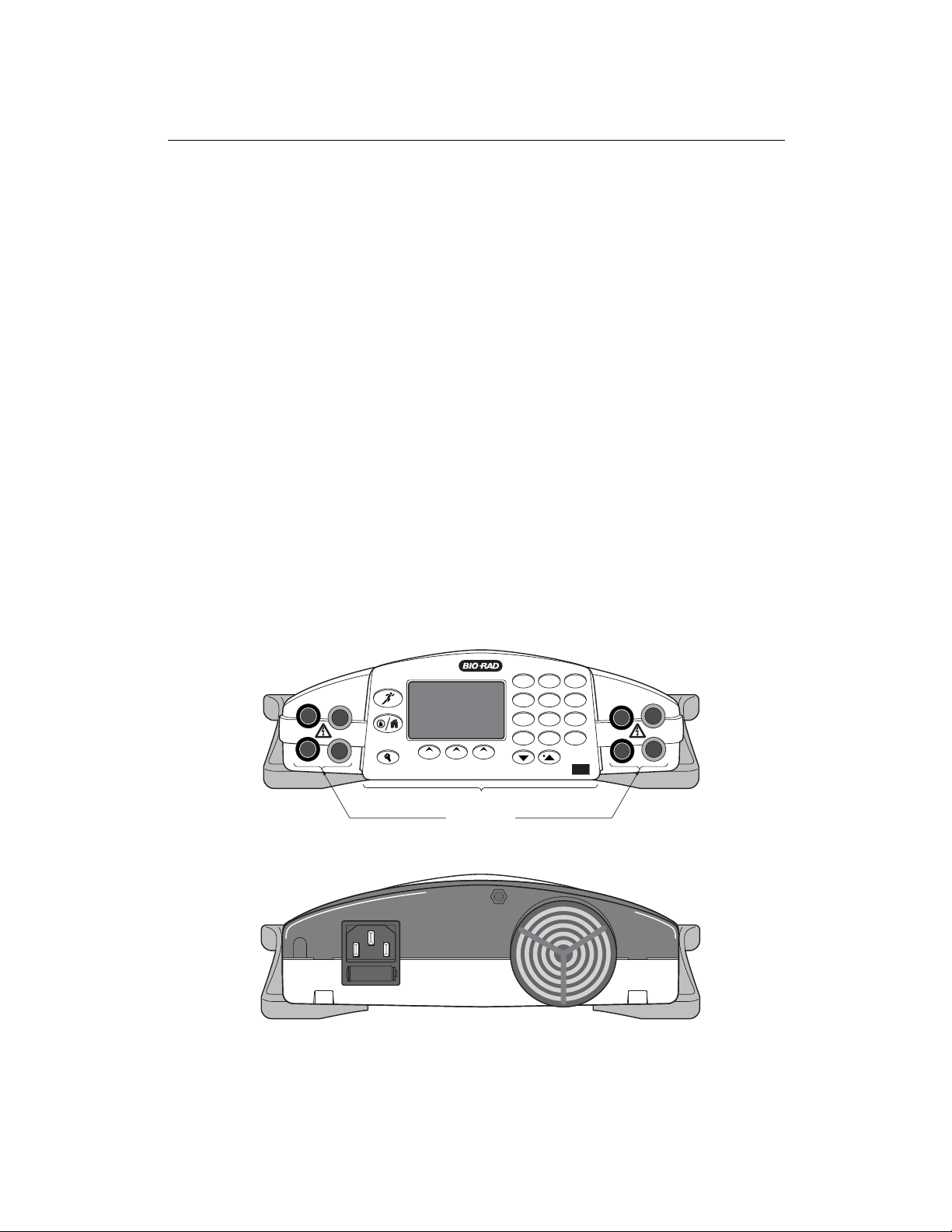
OUTPUT JACKS
FRONT PANEL
1 2
abc3def
4
ghi5jkl6mno
7
pqrs8tuv9wxyz
EDIT
0
CE
PowerPac HV – Instruction Manual
Section 1
Introduction
1.1 Overview
The PowerPac HV power supply is designed to provide constant voltage, current, or power
for a wide range of electrophoresis applications, including IEF and SDS PAGE. It also
provides temperature control for DNA sequencing with the Sequi-gen cell.
The PowerPac HV operates at the constant value specified by the user. If a non-constant
parameter becomes limiting, the PowerPac HV will automatically cross over and continue
operating at the limiting parameter.
Output range
Voltage 20–5,000 Volts (V)
Adjustable in 0.1 V increments from 20.0 to 99.9 V
Adjustable in 1 V increments from 100 to 5000 V
Current 0.05–500 mA.
Adjustable in 0.01 mA steps from 0.05 to 9.99 mA
Adjustable in 1 mA increments from 10 to 500 mA
Power 0.1–400 W
Adjustable in 0.1 Watt increments from 0.1 to 9.9 W
Adjustable in 1 W increments from 10 to 400 W
Output jacks Four sets of output jacks are provided to facilitate connection of up
to four identical electrophoresis cells simultaneously
Fig. 1. Front view.
Fig. 2. Rear view.
1

LEGS
(LOWERED POSITION)
1 2
abc3def
4
ghi5jkl6mno
7
pqrs8tuv9wxyz
EDIT
0
CE
PowerPac HV – Instruction Manual
1.2 Features
The PowerPac HV has the following features:
• Constant voltage, voltage ramping, constant current or constant power operation with
automatic crossover and temperature control mode
• Backlit LCD screen
• Continuous display of all parameters
• Continuous, timed and Volthours run control
• Nine (9) programmed runs, each containing up to nine steps
• Pause mode for editing running parameters
• Automatic detection of no-load, short circuit, rapid resistance change, ground leak, fan
failure and system overheating
• Automatic completion (if desired) of a run interrupted by AC power failure
• Stackable case with adjustable viewing angle (Figure 3)
• Adjustable LCD display contrast
• EN 61010 international safety certification
• Input power 100–120/220–240 VAC, 50/60 Hz, auto-switching
• Four output terminals
Fig. 3. Front panel with legs.
2

PowerPac HV – Instruction Manual
1.3 Unpacking
When the power supply is received, carefully inspect the container for any damage which
may have occurred in shipping. Severe damage to the container may indicate damage to the
power supply itself. If you suspect damage to the unit, immediately file a claim with the carrier
in accordance with their instructions before contacting Bio-Rad Laboratories.
Unpack the PowerPac HV. Remove the plastic film from the translucent green top case.
The plastic film may leave a residue. If so, clean with a soft, damp cloth.
Contents include:
• PowerPac HV power supply
• Power cord
• Instruction manual
• Warranty card
• Declaration of conformity
If any part is missing or damaged, contact Bio-Rad Laboratories immediately.
3
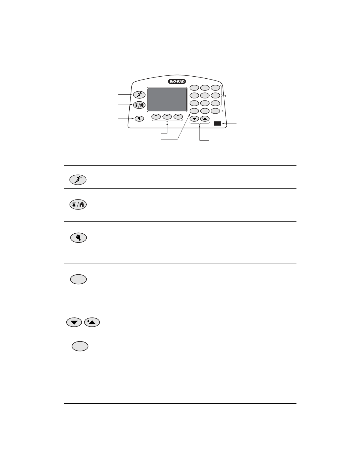
SETUP KEY
STOP/HOME KEY
RUN/PAUSE KEY
1 2
abc3def
4
ghi5jkl6mno
7
pqrs8tuv9wxyz
EDIT
0
CE
CLEAR ENTRY KEY
ALPHANUMERIC
KEYPAD
CURSOR KEYS
FUNCTION KEYS
EDIT KEY
IR PORT
PowerPac HV – Instruction Manual
Section 2
Control Panel
Fig. 4. Front Panel.
Key Description
Run/Pause Starts or pauses a run. When paused, the run parameters for the
current or subsequent step(s) may be edited. The modified method may
be stored to permanent memory by pressing SAVE at the end of the run.
Stop/Home Terminates the run in progress and displays the final run parameters, or
if no run is active, changes the display to the Home screen.
Note: If a method has been edited during a run, SAVE must be pressed
at the end of the run to save the changes.
Setup The SETUP menu allows the operator to set preferences. Press Setup
key again to exit the SETUP menu.
Preferences include: power failure detection, rapid resistance change
detection, no load detection, IR Data acquisition, contrast, key sound,
temperature probe check date and time settings (see Section 3.2).
EDIT Key Toggles soft key assignments between those used to set the run mode
EDIT
(constant voltage, constant current, or constant power), run
limits (voltage, current, or power) and time mode (hours, volt-hours, or
untimed).
Up & down Used to scroll through method list or method protocol. An asterisk (*) is
arrows and used to identify the selected method or step. The up arrow is used to
decimal point enter decimal point during parameter programming.
CE Clears alphanumeric characters from a parameter value or method name.
CE
It can be considered the backspace key.
Alphanumeric Used to enter parameter values and method names. When method
keypad names are entered, the manner in which keys are pressed determines
the characters entered and their placement. Rapid repetitive strokes on a
single key, toggles the character displayed at the cursor position. The
cursor position advances each time a different key is pressed or when
there is a pause between strokes of a single key. The “0” key accesses
the “pH” and hyphen “–” sequence.
Function or The function of the three soft keys is indicated by the legend displayed
Soft keys directly above the key. This will vary with the menu tree.
4
PowerPac HV – Instruction Manual
Section 3
Product Setup
3.1 Power Supply Connections
This section describes how the PowerPac HV power supply is connected to an electrophoresis
cell or cells.
Step Procedure Description
1. Connect the Connect one end of the included power cord to the
power cord rear of the instrument. Connect the other end to a
compatible power source.
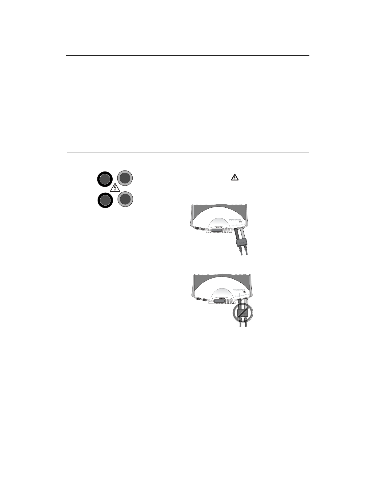
2. Connect cells Insert power leads into one of the output terminals
located on the front of the power supply (shown to
the left). Note that the symbol indicates high
voltages and that the
power leads must be inserted perpendicular to the
curve of the case (see below).
Fig. 5. Power Lead Connected Correctly
Fig. 6. Power Leads Connected Incorrectly
5
PowerPac HV – Instruction Manual
Step Procedure Description
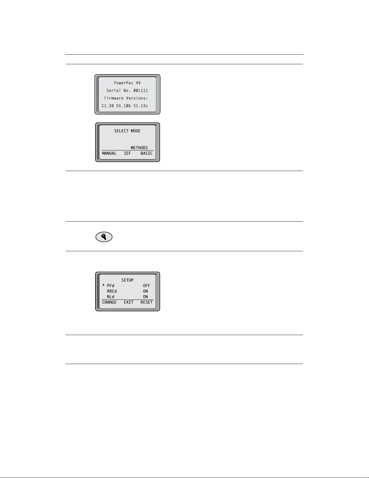
3. Turn power on Use the switch located on the right side of the power
supply to power on. Initially, the unit will display the
firmware version and serial number for a few seconds,
then go to the Home screen. The Home screen soft
keys are used to select operation modes; Manual
(Section 4.1), IEF Methods (Section 4.3), and Basic
Methods (Section 4.2).
To access the Temperature mode insert the leads
of the thermocouple probe into the connections at
the rear of the power supply (Section 4.4).
3.2 Preferences Setup
The PowerPac HV offers customizing options to enable and disable safety features and
infrared (IR) port, as well as LCD display contrast adjustment, key sound, and set local time
and date.
Step Procedure Description
1. Open the Setup editor Press SETUP to start the Setup editor. SETUP can
be pressed from any screen except the run screen.
2. Select the SETUP Scroll through the SETUP preferences using the
preference arrow keys. The asterisk indicates the selected
preference.
The soft key CHANGE toggles between the different
options or settings for the selected preference.
The RESET soft key allows the user to change all
the preference settings to the default values, except
for time and date.
3. EXIT Pressing the EXIT soft key or the SETUP key
accepts any changes made, and exits the SETUP
menu.
6
PowerPac HV – Instruction Manual
3.3 Explanation of Safety Features and Setup Options
3.3.1 Pfd: Power Failure Detection
Preference Options Description
PFd OFF OFF: Turns power failure detection OFF.
Power Failure Detection (Default) In this mode, the run is terminated if a
NEXT RUN power failure occurs.
ON
NEXT RUN: Turns power failure
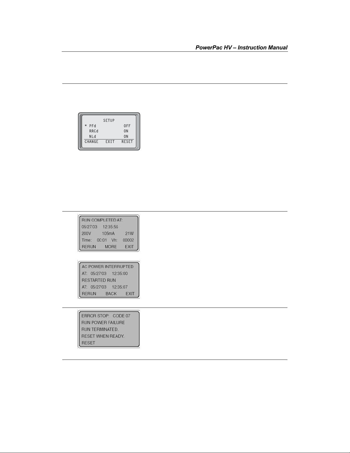
* PFd OFF
SETUP
RRCd ON
NLd ON
CHANGE EXIT RESET
1. If a power failure occurred during the run with
detection on for a single run. PFd will
show on the upper right corner of the
Run screen.
ON: Turns power failure detection mode
on in all runs. If there is a power failure in
this mode, then the run will resume when
the power is restored. PFd will show on
the upper right corner of the Run screen.
Warning: Turning the power supply off
(Stopping a run in progress with PFd
enabled, is regarded as a power failure.)
The "interrupted" run will resume
automatically when the power is
restored.
PFd enabled, the MORE soft key is displayed
on the Run Completed screen.
Press MORE to display details about the most
recent power outage and when power was
restored.
Press RERUN to restart the run.
Press BACK to return to the Run Completed
screen. Press EXIT to go to the Method screen.
2. Displayed if PFd = OFF
This error screen is displayed if a run has
terminated due to a power failure.
Press RESET to return to the Home screen.
7
 Loading...