

Page 1
Zeus3S
Installation Manual
ENGLISH
www.bandg.com
Page 2

Page 3
Preface
Disclaimer
As Navico is continuously improving this product, we retain the right to make changes to the
product at any time which may not be reflected in this version of the manual. Please contact
your nearest distributor if you require any further assistance.
It is the owner’s sole responsibility to install and use the equipment in a manner that will not
cause accidents, personal injury or property damage. The user of this product is solely
responsible for observing maritime safety practices.
NAVICO HOLDING AS AND ITS SUBSIDIARIES, BRANCHES AND AFFILIATES DISCLAIM ALL
LIABILITY FOR ANY USE OF THIS PRODUCT IN A WAY THAT MAY CAUSE ACCIDENTS, DAMAGE
OR THAT MAY VIOLATE THE LAW.
This manual represents the product as at the time of printing. Navico Holding AS and its
subsidiaries, branches and affiliates reserve the right to make changes to specifications
without notice.
Governing language
This statement, any instruction manuals, user guides and other information relating to the
product (Documentation) may be translated to, or has been translated from, another
language (Translation). In the event of any conflict between any Translation of the
Documentation, the English language version of the Documentation will be the official
version of the Documentation.
Copyright
Copyright © 2020 Navico Holding AS.
Warranty
The warranty card is supplied as a separate document. In case of any queries, refer to the
brand website of your unit or system:
www.bandg.com
Compliance statements
Declarations
The relevant declarations of conformity are available at:
www.bandg.com
Europe
Navico declare under our sole responsibility that the product conforms with the
requirements of:
• CE under RED 2014/53/EU
United States of America
Navico declare under our sole responsibility that the product conforms with the
requirements of:
• Part 15 of the FCC Rules. Operation is subject to the following two conditions: (1) this
device may not cause harmful interference, and (2) this device must accept any
interference received, including interference that may cause undesired operation
Warning: The user is cautioned that any changes or modifications not
expressly approved by the party responsible for compliance could void the
user’s authority to operate the equipment.
Note: This equipment generates, uses and can radiate radio frequency energy and, if not
Ú
installed and used in accordance with the instructions, may cause harmful interference
to radio communications. However, there is no guarantee that the interference will not
Preface | Zeus³S Installation Manual
3
Page 4

occur in a particular installation. If this equipment does cause harmful interference to
radio or television reception, which can be determined by turning the equipment off
and on, the user is encouraged to try to correct the interference by one or more of the
following measures:
• Reorient or relocate the receiving antenna
• Increase the separation between the equipment and receiver
• Connect the equipment into an outlet on a circuit different from that of the receiver is
connected
• Consult the dealer or an experienced technician for help
ISED Canada
This device complies with ISED (Innovation, Science and Economic Development) Canada’s
license-exempt RSSs. Operation is subject to the following two conditions: (1) This device
may not cause interference; and (2) This device must accept any interference, including
interference that may cause undesired operation of the device.
La traduction française de ce document est disponible sur le site Web du produit.
Australia and New Zealand
Navico declare under our sole responsibility that the product conforms with the
requirements of:
• level 2 devices of the Radiocommunications (Electromagnetic Compatibility) standard
2017
• radiocommunications (Short Range Devices) Standards 2014
Internet usage
Some features in this product use an internet connection to perform data downloads and
uploads.
Internet usage via a connected mobile/cell phone internet connection or a pay-per-MB type
internet connection may require large data usage. Your service provider may charge you
based on the amount of data you transfer. If you are unsure, contact your service provider to
confirm rates and restrictions.
Trademarks
Navico® is a registered trademark of Navico Holding AS.
B&G® is a registered trademark of Navico Holding AS.
Bluetooth® is a registered trademark of Bluetooth SIG, Inc.
CZone™ is a trademark of Power Products LLC.
FLIR® is a registered trademark of FLIR.
HDMI® and HDMI™, the HDMI Logo, and High-Definition Multimedia Interface are trademarks
or registered trademarks of HDMI Licensing LLC in the United States and other countries.
NMEA® and NMEA 2000® are registered trademarks of the National Marine Electronics
Association.
SD™ and microSD™ are trademarks or registered trademarks of SD-3C, LLC in the United
States, other countries or both.
Navico product references
This manual refers to the following Navico products:
• Broadband Radar™ (Broadband Radar)
• ForwardScan™ (ForwardScan)
• GoFree™ (GoFree)
• Halo™ Pulse Compression Radar (Halo Radar)
• StructureScan® (StructureScan)
4
Preface | Zeus³S Installation Manual
Page 5
About this manual
Images used in this manual might not exactly match the screen on your unit.
Important text conventions
Important text that requires special attention from the reader is emphasized as follows:
Note: Used to draw the reader’s attention to a comment or some important information.
Ú
Warning: Used when it is necessary to warn personnel that they should
proceed carefully to prevent risk of injury and/or damage to equipment/
personnel.
Intended audience
This manual is written for system installers.
The manual assumes that the reader has basic knowledge about this type of equipment with
regards to:
• installation work to be carried out
• nautical terminology and practices
Translated manuals
Available translated versions of this manual can be found on the following website:
• www.bandg.com
Preface | Zeus³S Installation Manual
5
Page 6

Contents
7 Introduction
7 Parts included
8 Front controls
9 Card reader
10 Connectors
11 Installation
11 General mounting guidelines
13 U-bracket mounting
14 Panel mounting
14 Bezel fitment and removal
15 Wiring
15 Connectors
15 Wiring guidelines
15 Power
18 NMEA 2000
19 Video IN and NMEA 0183
21 Ethernet
22 Sonar CH1 - blue connector
22 Sonar CH2 - black connector
23 HDMI out
23 USB port
25 System setup
25 Turning the system on and off
25 First time startup
25 System setup sequence
25 The settings dialog
25 System settings
27 Activating/deactivating features and applications
28 Alarms
28 Radar installation
31 Echosounder settings
34 Autopilot settings
34 Fuel settings
36 Wireless settings
36 Network settings
40 3rd party support
40 CZone
41 Naviop
41 FLIR camera setup
42 Appendix
42 Technical specifications
44 Dimensional drawings
45 Supported data
6
Contents | Zeus³S Installation Manual
Page 7
Introduction
A
C
B
D
E
Fa
G
Fb
1
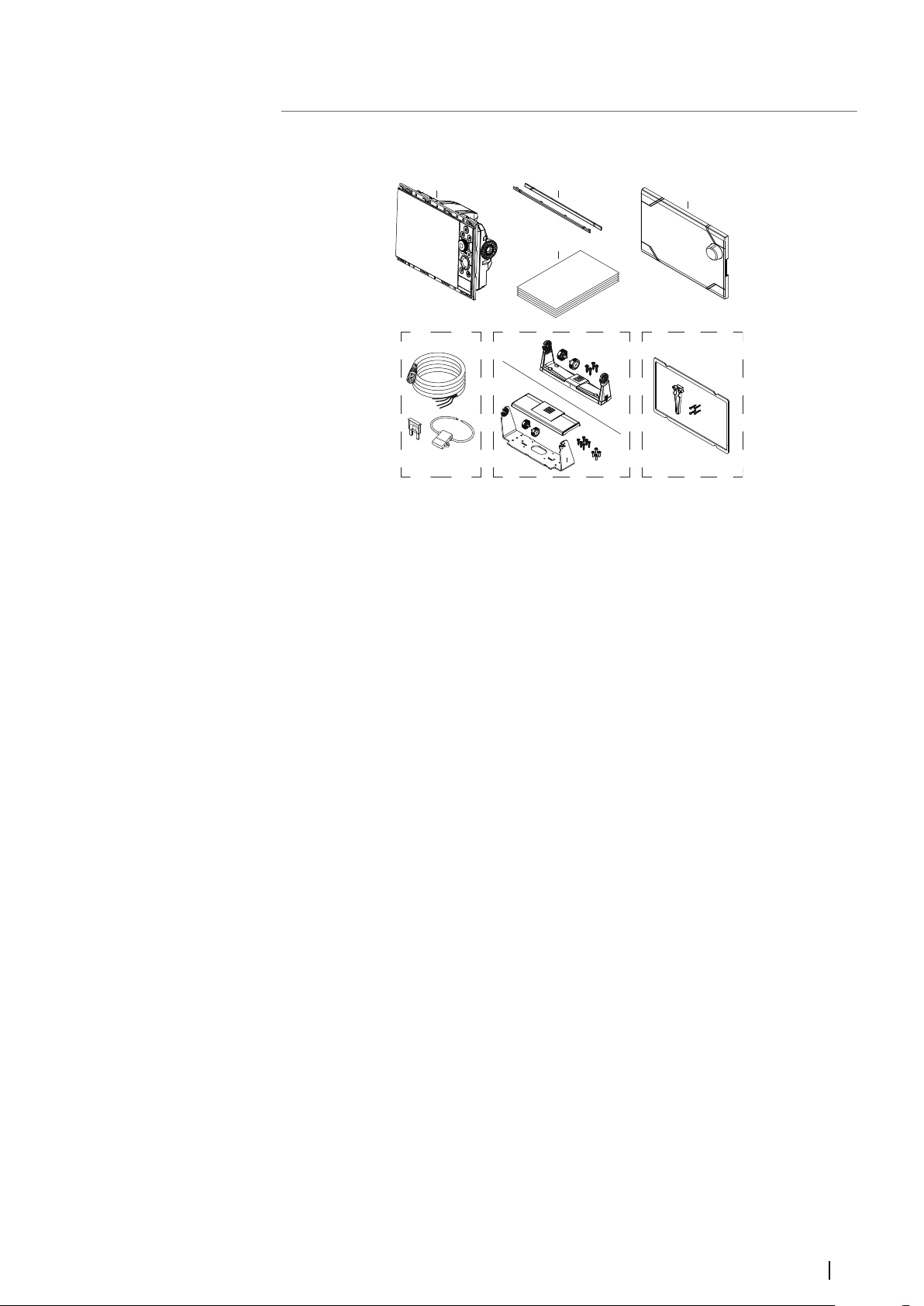
Parts included
A Display unit
B Bezel trim
C Documentation pack
D Sun cover
E Power cable kit
• Power cable
• Fuse
• Fuse holder
Fa U-bracket kit - 9" units
• Plastic U-bracket
• Bracket knobs
• Mounting screws
- 4x #10x3/4" self-tapping pan head
Fb U-bracket kit - 12" units
• Metal U-bracket
• Bracket cover
• Bracket knobs
• Mounting screws
- 6x #14x1" self-tapping pan head
- 4x M4x12 pan head
G Panel mounting kit
• Gasket
• Screw jig
Ú
• Mounting screws
- 9" and 12" units: 8x #4x1/2" self-tapping pan head
- 16" units: 12x #4x1/2" self-tapping pan head
Note: U-bracket kit for 16" units is sold separately.
Introduction | Zeus³S Installation Manual
7
Page 8
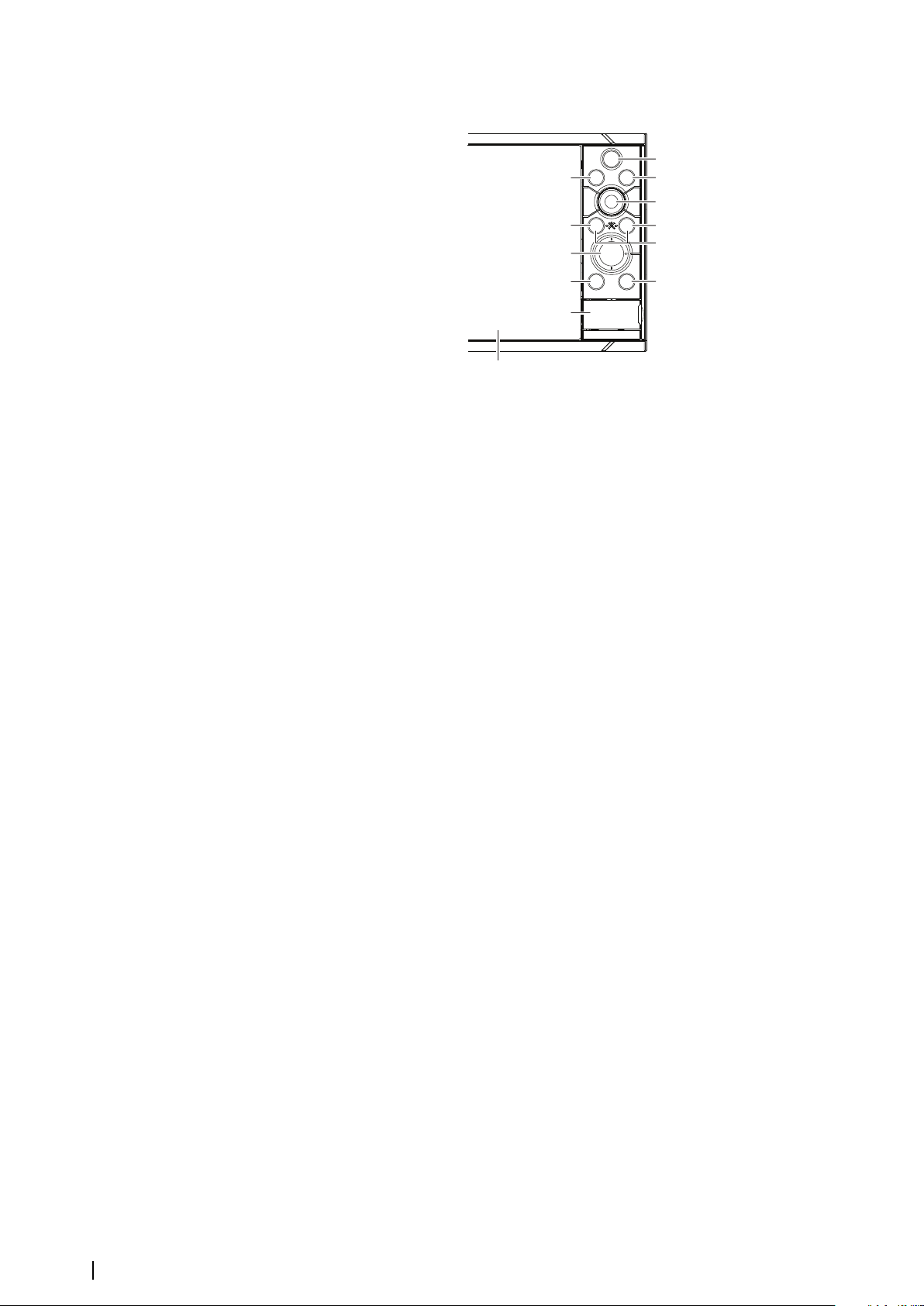
Front controls
A
K
E
B
G
C
D
F
I
J
L
H
A Touch screen
B Pages/Home
• Press to open the Home page for page selection and setup options.
C WheelKey - user configurable key. Refer to "Configure WheelKey" on page 26.
Default without an autopilot connected to the system:
• Short press: toggles between panels on split screen.
• Long press: maximizes active panel on split screen.
Default with an autopilot connected to the system:
• Short press: opens the autopilot controller and puts the autopilot in standby
mode.
• Long press: toggles between panels on split screen.
D Menu key
• Press to display the active panel's menu.
E Rotary knob
• Turn to zoom or scroll the menu, press to select an option.
F Enter key
• Press to select an option or to save settings.
G Exit key
• Press to exit a dialog, return to previous menu level, and clear the cursor from
the panel.
H MOB
• Press simultaneously the Enter and Exit keys to create a MOB at the vessel's
position.
I Arrow keys
• Press to activate the cursor or to move the cursor.
• Menu operation: press to navigate through menu items and to adjust a value.
8
J Mark key
• Press to place waypoint at vessel position or at cursor position when the cursor
is active.
• Press and hold to open the Plot dialog from where you can select options to
add new or manage existing waypoints, routes and tracks.
Introduction | Zeus³S Installation Manual
Page 9
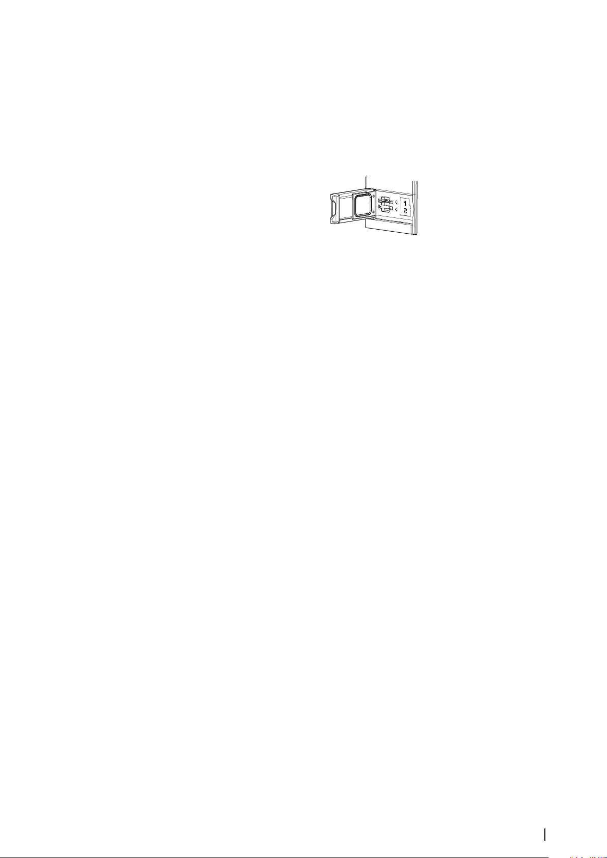
K Power key
• Press and hold to turn the unit ON/OFF.
• Press once to display the System Controls dialog. Repeat short presses to toggle
through the default dimming levels.
L Card reader door
Card reader
A memory card can be used for:
• Chart data
• Software updates
• Transfer of user data
• Logging user data
• System backup
Note: Do not download, transfer or copy files to a chart card. Doing so can damage chart
Ú
information on the chart card.
The protective door should always be securely shut immediately after inserting or removing
a card, in order to prevent possible water ingress.
Introduction | Zeus³S Installation Manual
9
Page 10
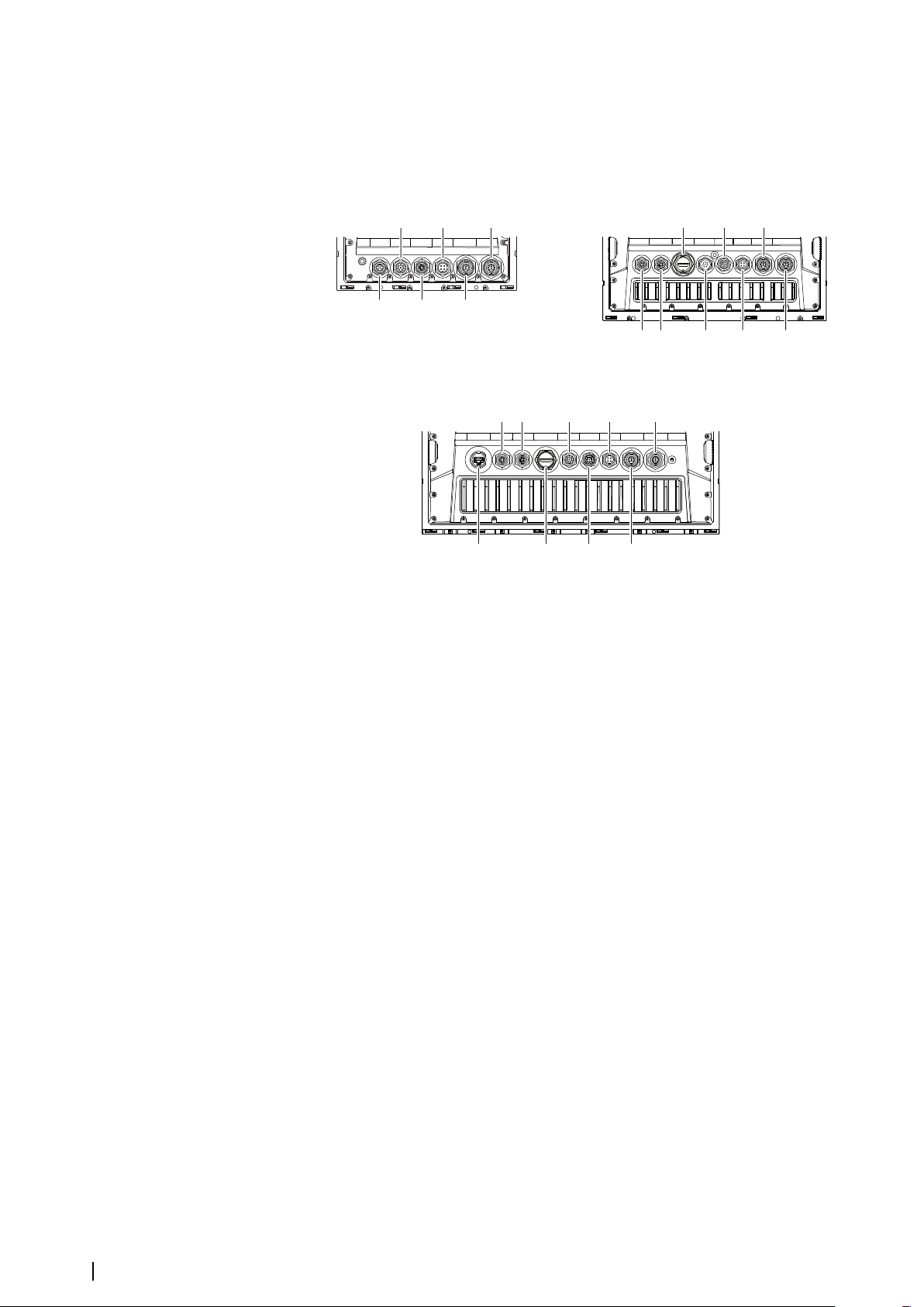
Connectors
E
F
SONAR 2
SONAR 1
POWERETHERNETVIDEONMEA2000
D
C
A
B
ETHERNET ETHERNET HDMI VIDEO NMEA2000
POWER SONAR 1
SONAR 2
A A
G
B
C
D E
F
ETHERNET ETHERNETUSB HDMI VIDEO NMEA2000 POWER SONAR 1 SONAR 2
AA
H G
BC
D E
F
Connectors
9" units
16" units
A Ethernet - Ethernet network
B Power - power, power control, and external alarm
C Video- composite video and NMEA0183
D NMEA 2000 - NMEA 2000 data
E Sonar CH1
F Sonar CH2
G HDMI - HDMI video output
H USB connector - mouse, keyboard or mass storage
12" units
10
Introduction | Zeus³S Installation Manual
Page 11
Installation
2
General mounting guidelines
Warning: Do not install the unit in a hazardous/flammable atmosphere.
Note: Choose a mounting location that will not expose the unit to conditions that
Ú
exceed the technical specifications.
Mounting location
Ensure that the selected area allows for:
• Cable routing, cable connection and cable support.
• Connection and use of portable storage devices.
• Viewing any LED indicators.
• Easy access to serviceable parts.
Do also consider:
• The free space around the unit to allow for adequate cooling.
• The mounting surface’s structure and strength, with regard to the weight of the
equipment.
• Any mounting surface vibration that might damage the equipment.
• Hidden electrical wires that might be damaged when drilling holes.
Ventilation
Inadequate ventilation and subsequent overheating of the unit will cause unreliable
operation and reduced service life.
Ventilation behind units is recommended for all units which are not bracket mounted.
Examples of enclosure ventilation options, in order of preference, are:
• Positive pressure air from the vessel's air conditioning system.
• Positive pressure air from local cooling fans (fan required at input, fan optional at outlet).
• Passive airflow from air vents.
Electrical and radio frequency interference
This unit conforms to the appropriate Electromagnetic Compatibility (EMC) regulations. To
ensure that the EMC performance is not compromised, the following guidelines apply:
• Separate battery used for the vessel engine.
• Minimum 1 m (3 ft) between the device, the device's cables and any transmitting
equipment or cables with radio signals.
• Minimum 2 m (7 ft) between the device, the device's cables and the SSB radio.
• More than 2 m (7 ft) between the device, the device's cables and the radar beam.
WiFi
It is important to test the WiFi performance before the location of the unit is decided.
Construction material (steel, aluminum, or carbon) and heavy structure might affect WiFi
performance.
The following guidelines apply:
• Select a location where there is a clear, direct line of sight between WiFi connected units.
• Keep the distance between WiFi units as short as possible.
• Mount the WiFi unit at least 1 m (3 ft) away from:
- Other WiFi enabled products.
- Products that send wireless signals in the same frequency range.
- Equipment that might generate interference.
Installation | Zeus³S Installation Manual
11
Page 12
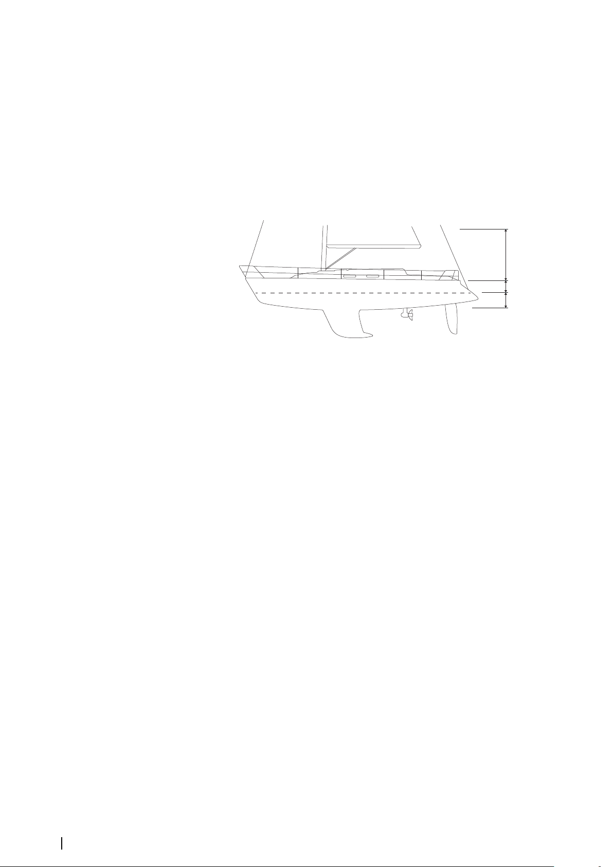
Compass safe distance
A
B
C
The unit outputs electromagnetic interference that can cause inaccurate readings on a
nearby compass. To prevent compass inaccuracy the unit must be mounted far enough
away so the interference does not affect compass readings. For minimum compass safe
distance, refer to "Technical specifications" on page 42.
GPS
It is important to test the GPS performance before the location of the unit is decided.
Construction material (steel, aluminum, or carbon) and heavy structure might affect GPS
performance. Avoid a mounting location where metal obstacles block the view of the sky.
A well placed external GPS module can be added to overcome poor performance.
A Optimal location (above deck)
B Less effective location
C Not recommended location
Note: Consider the lateral swinging if mounting the GPS sensor high above the sea level.
Ú
Roll and pitch might give false positions and affect the true directional movement.
Touchscreen
Touchscreen performance can be affected by the location of the unit. Avoid locations where
the screen is exposed to:
• Direct sunlight.
• Prolonged rainfall or floating water.
12
Installation | Zeus³S Installation Manual
Page 13
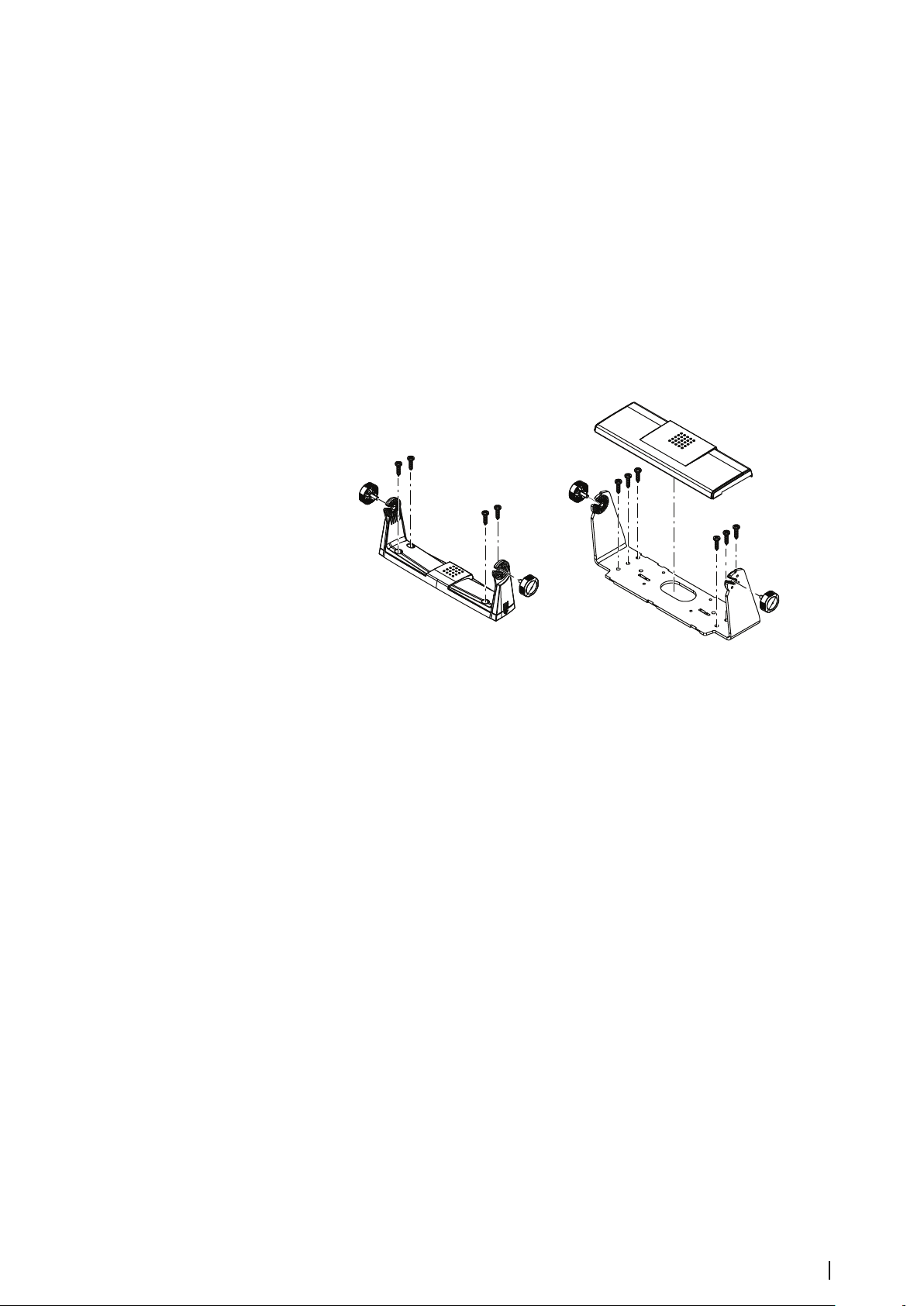
U-bracket mounting
1 Place the bracket in the desired mounting location. Ensure that the chosen
location has enough height to accommodate the unit fitted in the bracket, and
allows tilting of the unit. Also adequate space is required on both sides to allow
tightening and loosening of the knobs.
2 Mark the screw locations using the bracket as a template, and drill pilot holes.
3 Screw down the bracket using fasteners that are suitable for the material you are
mounting the bracket on.
4 For metal brackets, install the plastic cover over the lower part of the bracket.
5 Mount the unit to the bracket using the knobs. Hand tighten only.
The screws shown below are for illustration purposes only. Use fasteners that are suitable for
the material you are mounting the bracket on.
Installation | Zeus³S Installation Manual
13
Page 14
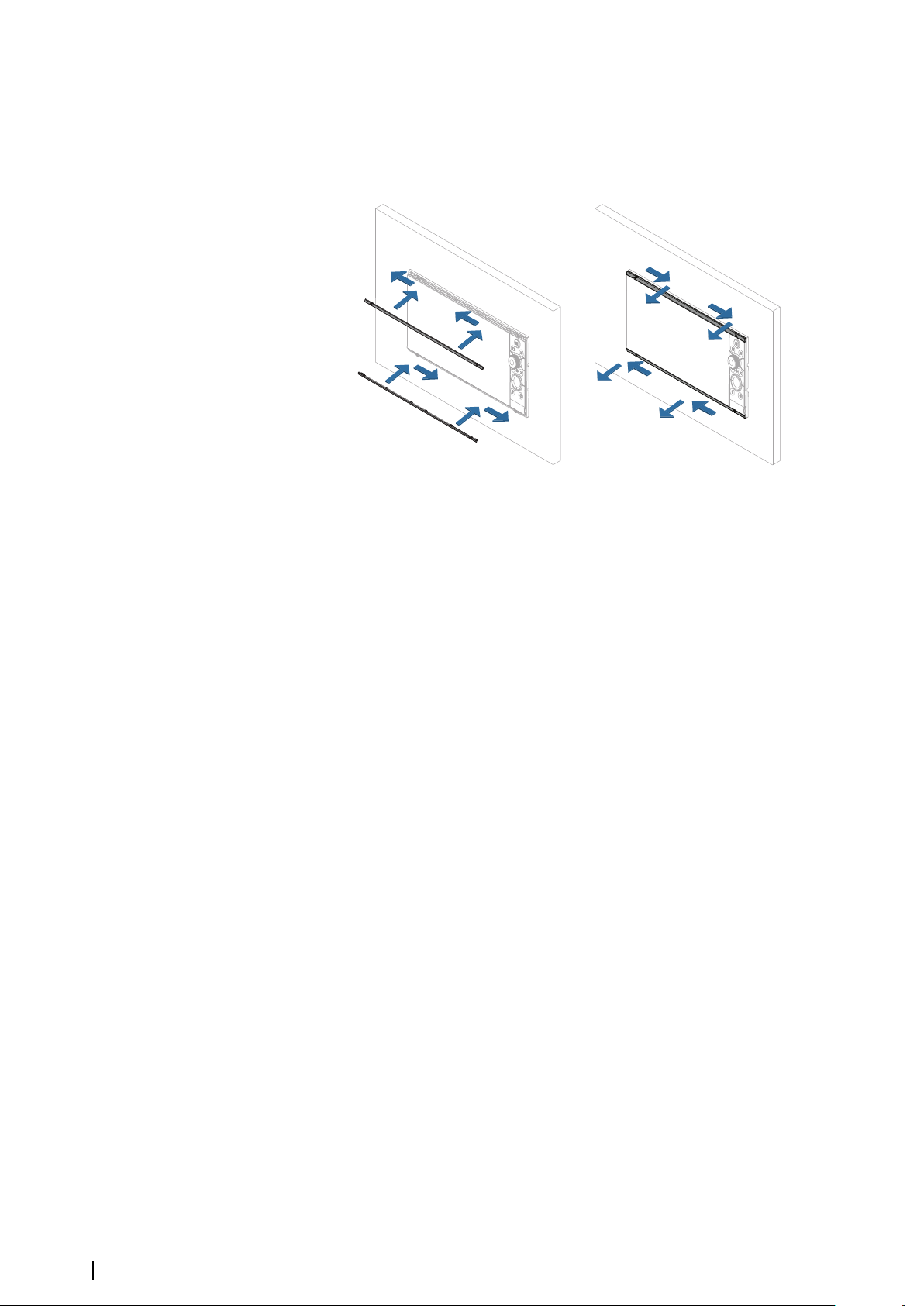
Panel mounting
Refer to the separate mounting template for panel mounting instructions.
Bezel fitment and removal
Note: The unit in the illustration is an example only.
Ú
14
Installation | Zeus³S Installation Manual
Page 15

Wiring
3
41
2
3
Connectors
Different models have different connectors. For available connectors and connector layout
refer to "Connectors" on page 10.
Wiring guidelines
Don't:
• Make sharp bends in the cables.
• Run cables in a way that allows water to flow down into the connectors.
• Run the data cables adjacent to radar, transmitter, or large/high current carrying cables or
high frequency signal cables.
• Run cables so they interfere with mechanical systems.
• Run cables over sharp edges or burrs.
Do:
• Make drip and service loops.
• Use cable-ties on all cables to keep them secure.
• Solder/crimp and insulate all wiring connections if extending or shortening the cables.
Extending cables should be done with suitable crimp connectors or solder and heat
shrink. Keep joins as high as possible to minimize possibility of water immersion.
• Leave room adjacent to connectors to ease plugging and unplugging of cables.
Warning: Before starting the installation, be sure to turn electrical power
off. If power is left on or turned on during the installation, fire, electrical
shock, or other serious injury may occur. Be sure that the voltage of the
power supply is compatible with the unit.
Warning: The positive supply wire (red) should always be connected to
(+) DC with a fuse or a circuit breaker (closest available to fuse rating).
Power
The power connector is used for power, power control and for external alarm output.
Power connector details
Unit socket (male)
Pin Purpose
1 DC negative
2 External alarm
3 Power control
4 +12/24 V DC
Power connection
The unit is designed to be powered by 12 or 24 V DC system.
Wiring | Zeus³S Installation Manual
15
Page 16
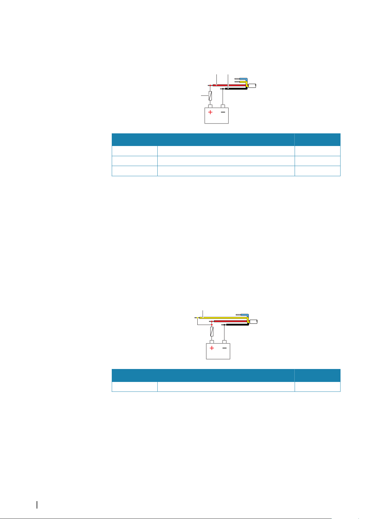
It is protected against reverse polarity, under voltage, and over voltage (for a limited
C
A B
A
duration).
A fuse or circuit breaker should be fitted to the positive supply. For recommended fuse rating
refer to "Technical specifications" on page 42.
Key Purpose Color
A +12/24 V DC Red
B DC negative Black
C Fuse
Power control connection
The yellow wire in the power cable can be used to control how the unit is turned on and off.
Power controlled by power key
The unit will turn on/off when the power key on the unit is pressed.
Leave the yellow power control wire disconnected and tape or heat-shrink the end to
prevent shorting.
Power control by supply power
The unit will turn on/off without using the power key when power is applied/removed.
Connect the yellow wire to the red wire after the fuse.
Note: The unit cannot be powered down by power button, but can be put in to standby
Ú
mode (the screen backlight turns off).
Key Purpose Color
A Power control wire, connected to supply power Yellow
16
Power controlled by ignition
The unit will turn on once ignition is turned on to start engines.
Note: Engine start batteries and house batteries should have a common ground
Ú
connection.
Wiring | Zeus³S Installation Manual
Page 17
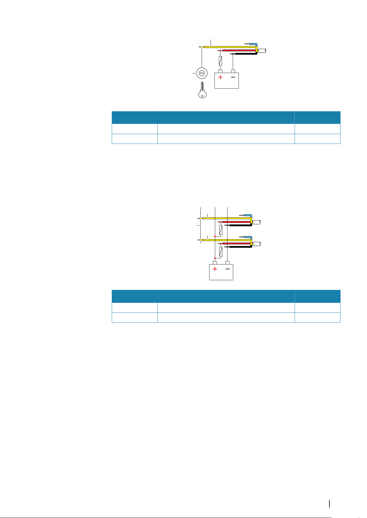
A
B
Key Purpose Color
A
B
A
A Power control wire Yellow
B Ignition switch
Power controlled by power bus
The yellow power control wire can either be an input that will turn on the unit when power
is applied, or an output that turns on other devices when the unit is powered on. It can be
configured at the installation stage to control the power state of displays and compatible
devices. When commissioning the system, the unit can be set to be a power control slave or
power control master.
Key Purpose Color
A Power control wire Yellow
B Power control bus
If a unit is configured as power control master and turned on by the power key, it will output
voltage on the power bus. This will power on both other power master units and power
slave units. If a unit is set to power control slave, it cannot be powered down using its own
power key while a power control master unit is turned on. Pressing the power key will set the
unit to standby. If all power control masters are off, power control slaves can be turned on
and off using their own power key. However, this will not turn on any other units connected
to the power bus.
Wiring | Zeus³S Installation Manual
17
Page 18
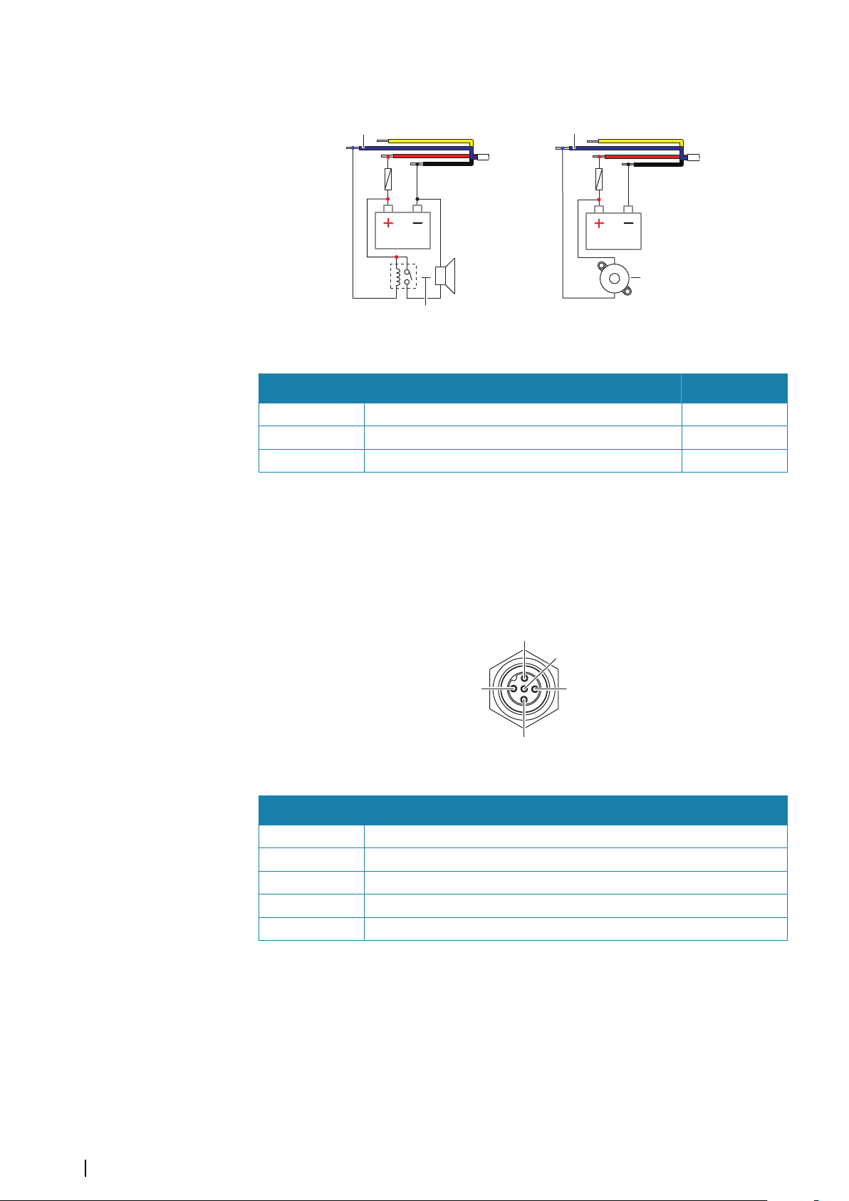
External alarm
A A
B
C
2
1
3
4
5
For sirens that draw more than 1 A, use a relay.
Key Purpose Color
A External alarm output Blue
B Siren and relay
C Buzzer
NMEA 2000
The NMEA 2000 data port allows receiving and sharing of a multitude of data from various
sources.
Connector details
Unit socket (male)
Pin Purpose
1 Shield
2 NET-S (+12 V DC)
3 NET-C (DC negative)
4 NET-H
5 NET-L
18
Plan and install an NMEA 2000 network
An NMEA 2000 network consists of a powered backbone from which drop cables connect to
NMEA 2000 devices. The backbone needs to run within 6 m (20 ft) of the locations of all
products to be connected, typically in a bow to stern layout.
The following guidelines apply:
• The total length of the backbone should not exceed 100 meters (328 ft).
• A single drop cable has a maximum length of 6 meters (20 ft). The total length of all drop
cables combined should not exceed 78 meters (256 ft).
Wiring | Zeus³S Installation Manual
Page 19
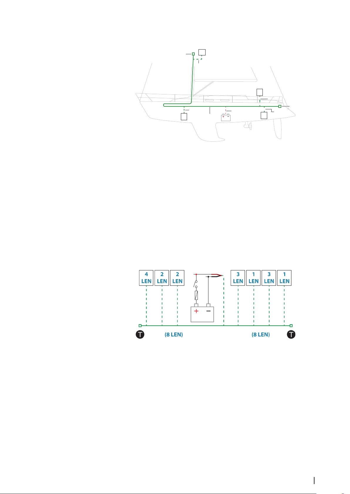
• A terminator must be installed at each end of the backbone. The terminator can be a
A
A
A
A
C
C
D
B
B
B
B
E
terminator plug or a unit with built-in terminator.
A NMEA 2000 device
B Drop-cable
C Terminator
D Power supply
E Backbone
Powering the NMEA 2000 network
The network requires its own 12 V DC power supply, protected by a 3 amp fuse.
For smaller systems: connect power at any location in the backbone.
For larger systems: connect power at a central point in the backbone to balance the voltage
drop of the network. Make the installation such that the load/current draw on each side of
the power node is equal.
Note: 1 LEN (Load Equivalency Number) equals 50 mA current draw.
Ú
Note: Do not connect the NMEA 2000 power cable to the same terminals as the engine
Ú
start batteries, autopilot computer, bow thruster or other high current devices.
Video IN and NMEA 0183
The unit has a combined Video IN and NMEA 0183 connector. The connector is labelled
VIDEO on the rear of the unit.
Wiring | Zeus³S Installation Manual
19
Page 20
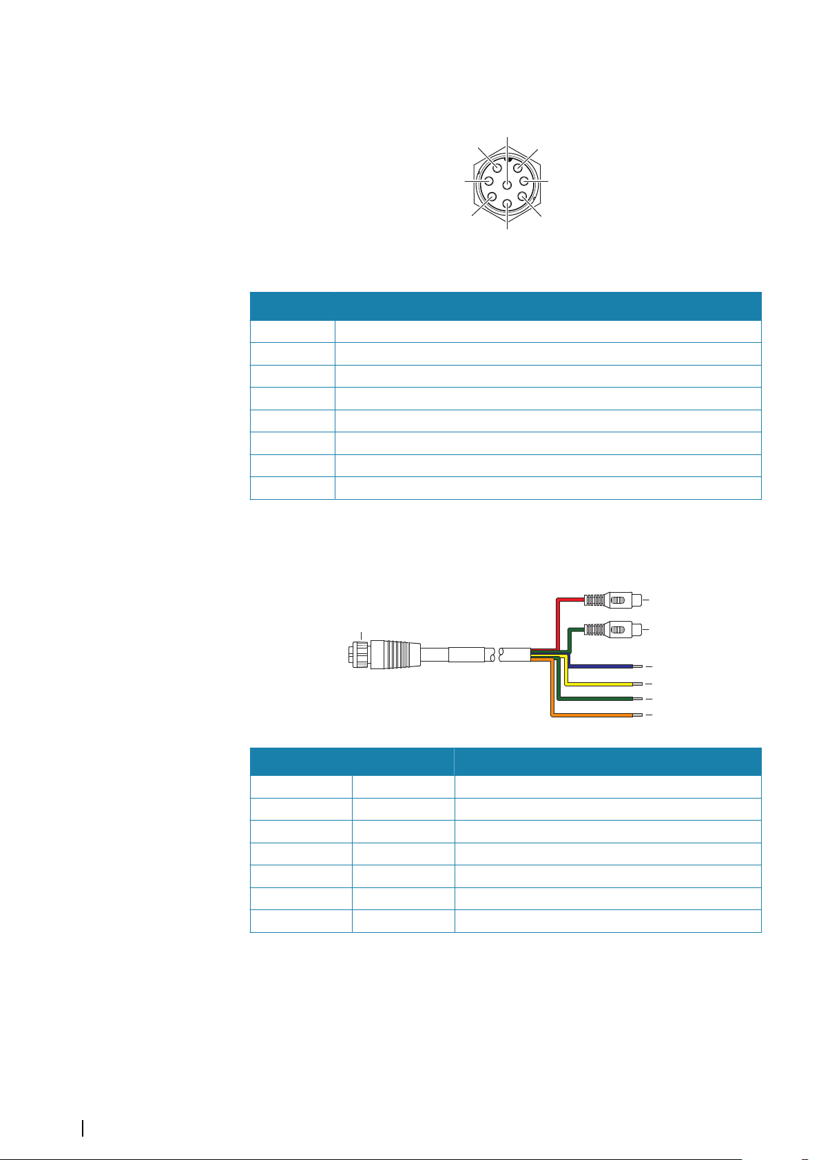
Connector details
7
6
2
4
8
3
5
1
D
E
F
G
A
B
C
Pin Purpose
1 Video 1 Ground
2 Video 1 (+)
3 Video 2 Ground
4 Video 2 (+)
5 NMEA 0183 TX_B
6 NMEA 0183 TX_A
7 NMEA 0183 RX_A
8 NMEA 0183 RX_B
Unit socket (male)
VIDEO IN/NMEA 0183 cable
Note: This cable (part number 000-00129-001) is not included with the unit.
Ú
Key Color Purpose
A Video in/data cable connector to unit
B Red Camera input 1 (RCA coaxial connector)
C Green Camera input 2 (RCA coaxial connector)
D Blue NMEA 0183 TX_B
E Yellow NMEA 0183 TX_A
F Green NMEA 0183 RX_A
G Orange NMEA 0183 RX_B
Video input
The unit can be connected to a composite video source, and display video images on its
display.
Note: Camera cables are not supplied, and will need to be selected to suit termination -
20
Ú
Wiring | Zeus³S Installation Manual
RCA at the unit, and typically BNC or RCA plug at the camera end.
Page 21
Note: The video images will not be shared with another unit via the network. It is only
1
2
3
4
5
Ú
possible to view video on the unit connected to the video source.
Note: Both NTSC and PAL formats are supported.
Ú
Video input configuration
Configurations to video input are made in the video panel. Refer to the Operator Manual for
more information.
NMEA 0183
The unit has a built in NMEA 0183 serial interface, providing both input and output. The
port(s) uses the NMEA 0183 (serial balanced) standard, and can be configured in the software
for different baud rates up to 38,400 baud.
Talkers and listeners
Only one talker (output device) can be connected to a serial input (RX) on the unit, in
accordance with the NMEA0183 protocol. However, an output port (TX) on the unit may be
connected to up to three listener (receiver) devices, dependent on the hardware capabilities
of the receiver.
Ethernet
The Ethernet port(s) can be used for transfer of data and synchronization of user created
data. It is recommended that each device in the system is connected to the Ethernet
network.
No special setup is required for establishing an Ethernet network.
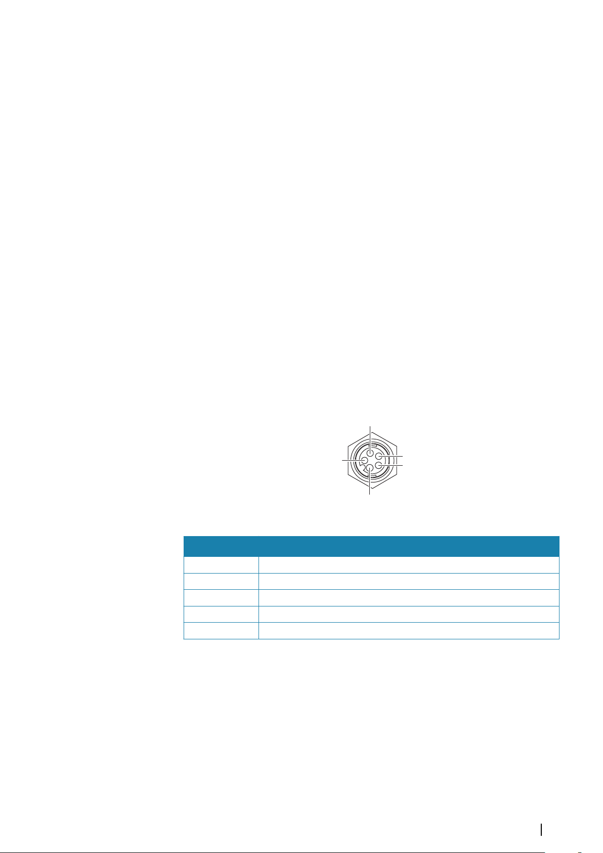
Ethernet connector details
Unit socket (female)
Pin Purpose
1 Transmit positive TX+
2 Transmit negative TX-
3 Receive positive RX+
4 Receive negative RX-
5 Shield
Ethernet expansion device
Connection of network devices can be made via an Ethernet expansion device. Additional
expansion devices can be added to provide the required number of ports.
Wiring | Zeus³S Installation Manual
21
Page 22
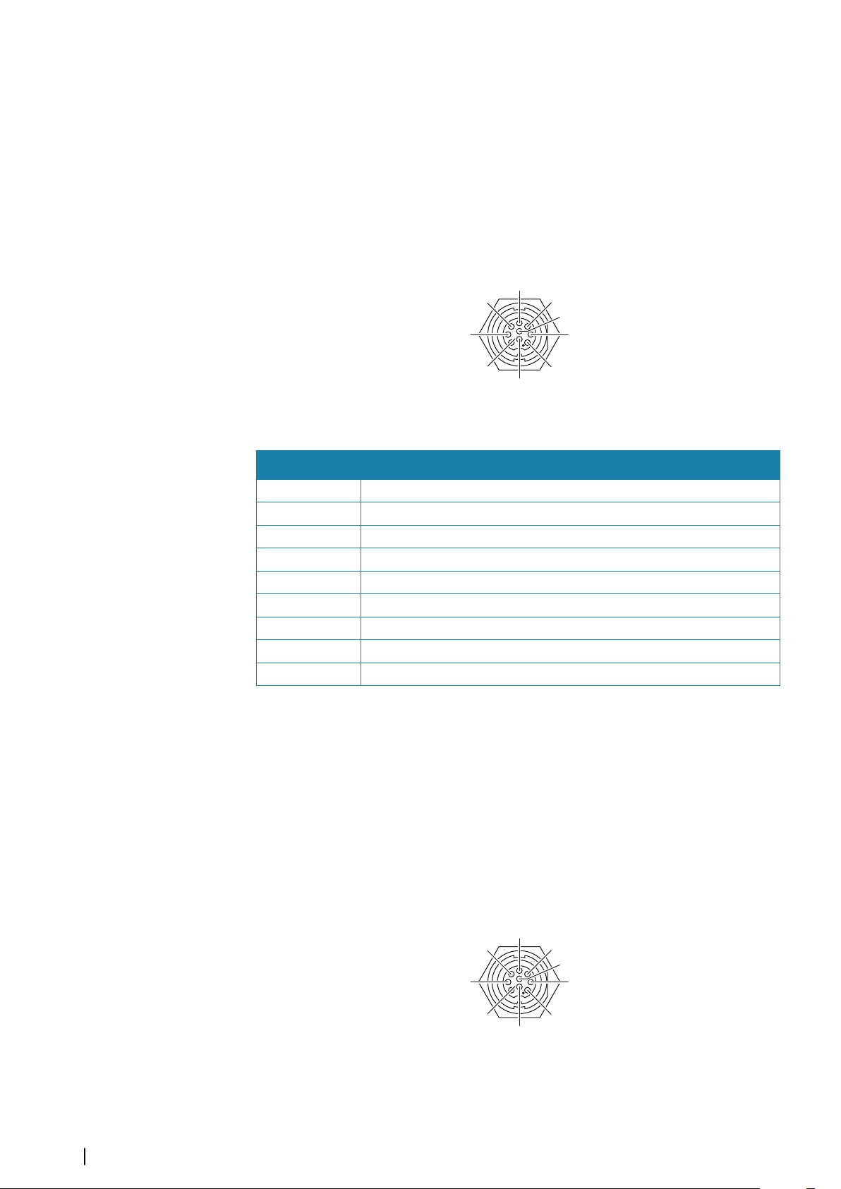
Sonar CH1 - blue connector
6
7
9
1
3
4
5
2
8
6
7
9
1
3
4
5
2
8
Supports:
• Sonar / CHIRP Sonar
Note: A 7-pin transducer cable can be connected to a 9-pin port using a 7-pin to 9-pin
Ú
adaptor cable. However, if the transducer has a paddle wheel speed sensor, the waterspeed data will not be displayed on the unit.
Connector details
Unit socket (female)
Pin Purpose
1 Drain/Ground
2 Not used
3 Not used
4 Transducer -
5 Transducer +
6 Not used
7 Not used
8 Temp +
9 Transducer ID
Sonar CH2 - black connector
Supports:
• Sonar / CHIRP Sonar
• ForwardScan
Note: A 7-pin transducer cable can be connected to a 9-pin port using a 7-pin to 9-pin
Ú
adaptor cable. However, if the transducer has a paddle wheel speed sensor, the waterspeed data will not be displayed on the unit.
Connector details
Unit socket (female)
22
Wiring | Zeus³S Installation Manual
Page 23
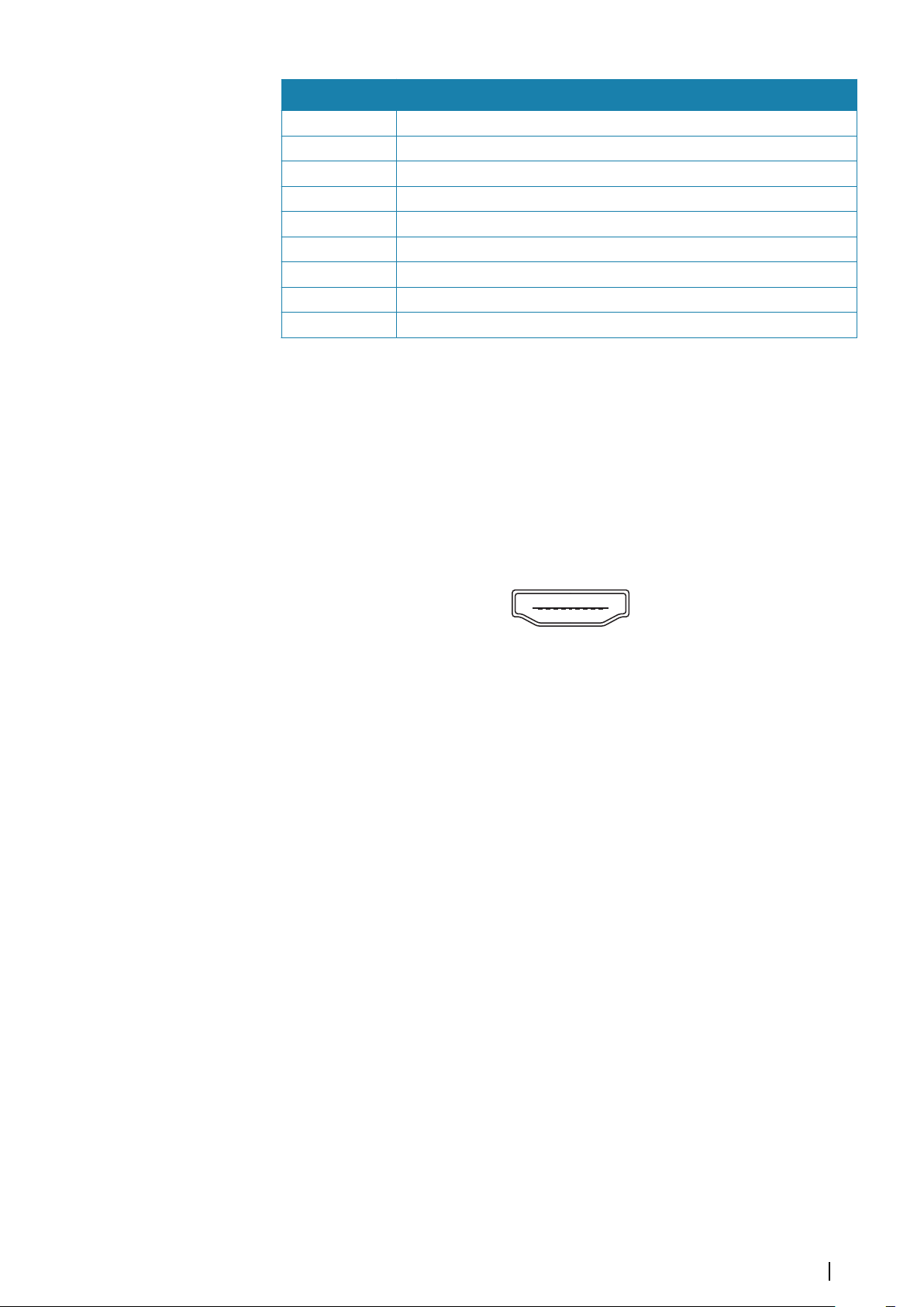
Pin Purpose
1 Drain/Ground
2 Starboard +
3 Starboard -
4 Transducer -
5 Transducer +
6 Port +
7 Port -
8 Temp
9 Transducer ID
HDMI out
The unit can be connected to an external monitor to replicate video at a remote location.
The image is shown on the external monitor at the units own native resolution, so the
external monitor should support the same resolution or be able to scale.
Note: Some HDMI TV displays may apply over-scan, which will in effect crop the image
Ú
possibly causing loss of important content. Check the display manual for an option to
disable over-scan or adjust scaling.
HDMI connector details
Unit socket (female)
The unit is equipped with standard HDMI (Type A) connector(s).
HDMI cable requirements
Note: The unit should be turned off prior to connecting or disconnecting an HDMI cable.
Ú
While the HDMI standard does not state maximum cable length, signal may be
compromised on long runs. Only use Navico or other high quality HDMI certified cables. 3rd
party cables should be tested before installation. On runs over 10 m it may be required to
add an HDMI amplifier or use HDMI-CAT6 adaptors.
USB port
The USB port can be used to:
• Connect a keyboard.
• Connect a mouse.
• Charge a connected device. For maximum output power refer to the "Technical specifications"
on page 42.
• Connect a storage device.
• Connect a card reader.
Note: If you want to read chart cards using a USB card reader connected to the USB port,
Ú
an MI10 USB card reader is required.
The USB devices should be standard PC compatible hardware.
Note: USB cable length should not exceed 5 m when using regular cables. Lengths over
Ú
5 m may be possible with the use of an active USB cable.
Wiring | Zeus³S Installation Manual
23
Page 24

USB connector details
Unit socket (female)
The unit is equipped with standard USB type-A connector(s).
24
Wiring | Zeus³S Installation Manual
Page 25
System setup
4
Turning the system on and off
The system is turned on by pressing the Power key.
Press and hold the Power key to turn the unit off.
If the key is released before the shut-down is completed, the power off process is cancelled.
You can also turn the unit off from the System Controls dialog.
Note: If the unit power is controlled by the power control wire, refer to power control
Ú
wiring for details about turning the unit on and off.
First time startup
When the unit is started for the first time, or after a reset, the unit displays a series of dialogs.
Respond to the dialog prompts to make fundamental settings.
You can perform further setup and later change settings using the system settings dialogs.
System setup sequence
1 General settings - refer to "System settings" on page 25.
• Make general settings as desired.
• Configure the power control.
2 Advanced settings - refer to "Advanced" on page 26.
• Enable or disable features.
• Review the advanced setting options and make changes as desired.
3 Source selection - refer to "Network settings" on page 36.
• Make sure that the proper external data sources have been selected.
4 Feature setup
• Configure specific features as described later in this chapter.
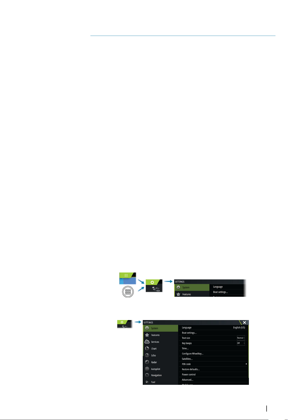
The settings dialog
The system setup is done from the settings dialog.
System settings
System setup | Zeus³S Installation Manual
25
Page 26
Boat settings
Used to specify the physical attributes of the boat.
Time
Configure time settings to suit vessel location, along with time and date formats.
Configure WheelKey
Configures the action of the WheelKey on the front of the unit.
PIN code
Sets a PIN code to prevent unauthorized access to your system's settings.
Note: Record the PIN code and store it in a safe place.
When you establish password protection, the PIN code must be entered when any of the
following are selected. After the correct PIN code is entered, all of them can be accessed
without re-entering the PIN code.
• Settings, activated from the home page or system controls dialog
• Alarms, activated from the toolbar
• Storage, activated from the toolbar
• Store, activated from the toolbar
Power control setup
Determines unit response to signals applied to the power control wire. Refer to "Power control
connection" on page 16.
This setting is only applicable if the yellow wire is used for power control.
• Set to slave if the power control wire is connected directly to power, the ignition switch, or
to a stand-alone switch. The unit should also be set to slave if you want the unit to behave
as a slave when connected to a power control bus.
• Set to master to make this unit turn other devices connected to the power control bus on
and off.
When a master unit is turned on or off, all units connected to the same power control bus
turns on or off.
While a master unit is on, a slave unit cannot be turned off.
If no master unit is turned on, slave units can be turned on and off individually.
Advanced
Used for configuration of advanced settings and how your system displays various user
interface information.
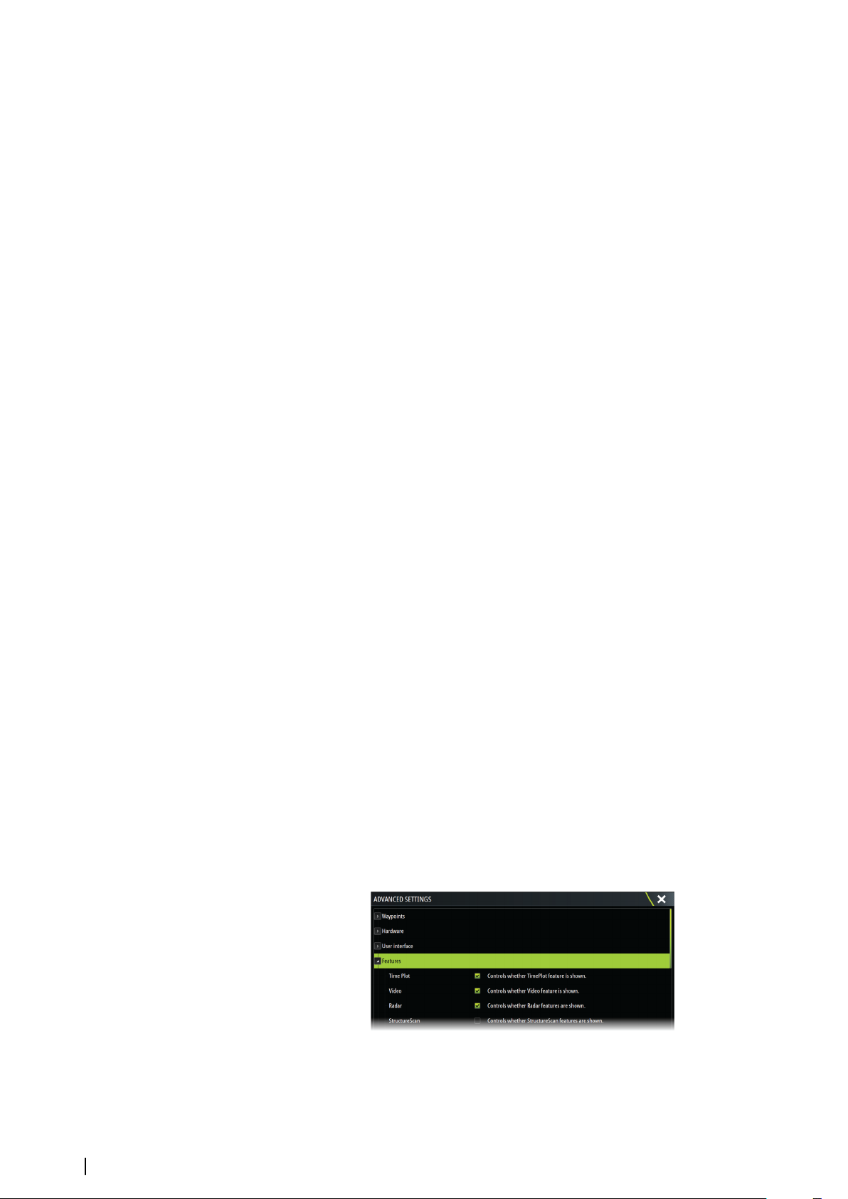
Enabling or disabling features
Use the feature option to enable or disable features that are not automatically enabled or
disabled by the system.
Rotating mast compensation
If the vessel is fitted with a rotating mast it will impact any sensors or radar mounted to it.
Provided the mast is also fitted with a sensor to measure rotation, the effect can be
compensated for.
26
System setup | Zeus³S Installation Manual
Page 27
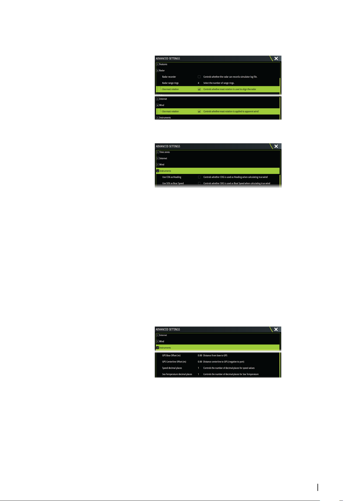
Note: If using H5000 with a rotating mast, use mast rotation for wind needs to be
Ú
disabled as the H5000 CPU will automatically correct the wind information relative to the
vessel.
SOG as boat speed and COG as heading
Use SOG as boat speed
If boat speed is not available from a paddle wheel sensor, it is possible to use speed over
ground from a GPS. SOG will be displayed as boat speed and used in the true wind
calculations and the speed log.
Use COG as heading
If heading data is not available from a compass sensor, it is possible to use COG from a GPS.
COG will be used in the true wind calculations.
Note: The autopilot cannot be operated using COG as the heading source. COG cannot
Ú
be calculated when stationary.
GPS offset - start line configuration
In order for the start line feature to work at it’s optimum, the exact position of the vessels
bow must be known. This is achieved by entering position offsets for the GPS sensor. These
offsets combined with heading data will allow the software to accurately determine the
bows distance from the start line.
GPS Bow Offset
Enter the distance from bow to GPS (always a positive value)
Note: Ensure the bow offset includes any projections forward of the hull, such as a
Ú
bowsprit.
GPS Centerline offset
Enter the distance from vessel centerline to GPS (negative to port)
Activating/deactivating features and applications
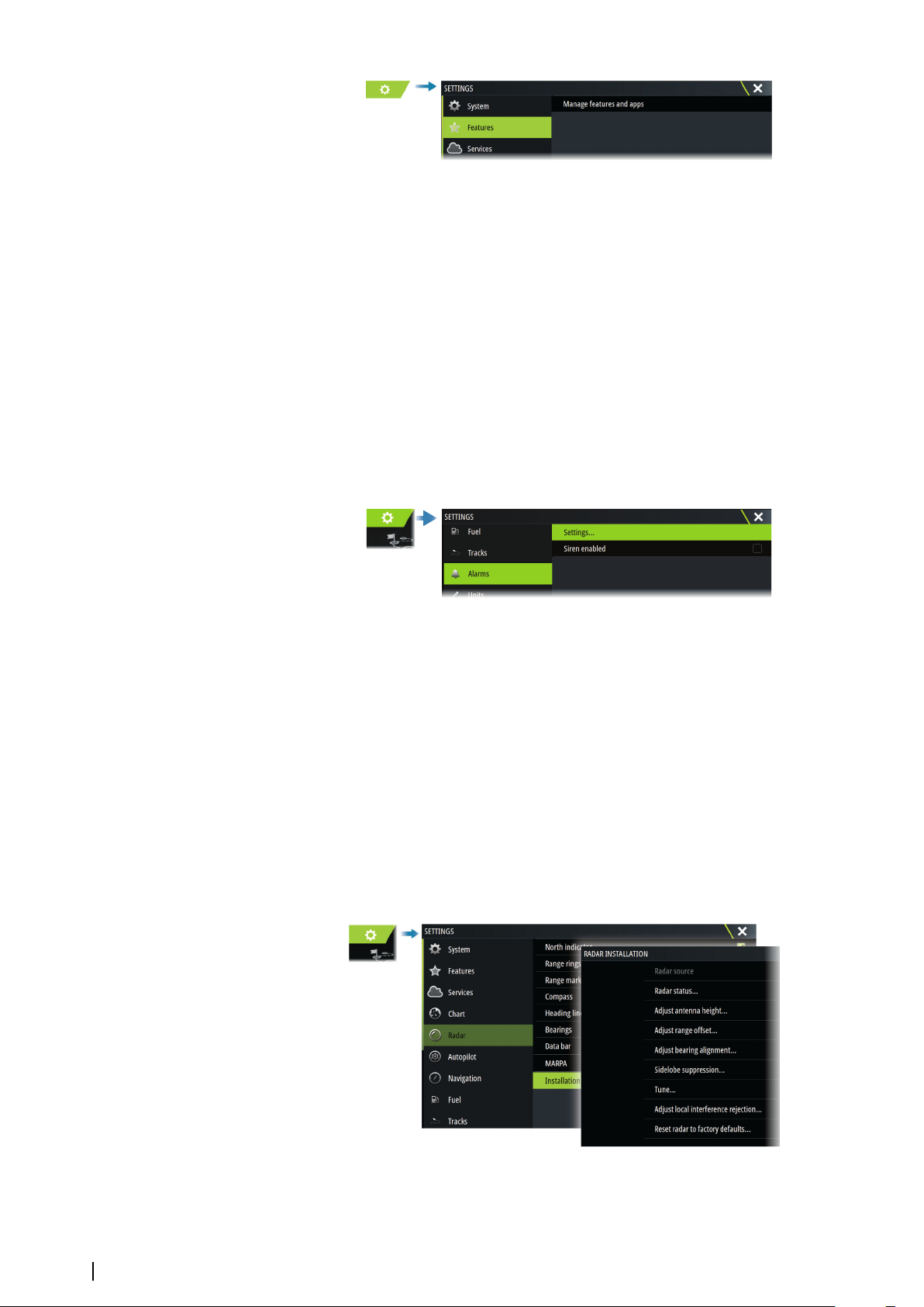
Use the system settings features option to activate/deactivate features and applications.
System setup | Zeus³S Installation Manual
27
Page 28
Manage features and applications
You can manage and install/uninstall the features and apps. When a feature/app is
uninstalled, the icon is removed from the home page. The feature/application can be
installed again.
Feature unlock
Some additional features can be sold separately. These features can be unlocked by entering
an unlock code.
Select the feature you want to unlock. Follow the instructions to purchase and enter the
feature unlock code.
After a feature unlock code is entered in the unit, the feature is available for use.
Note: The feature unlock option is only available if your unit supports a locked feature.
Ú
Alarms
Settings
List of all available alarm options in the system, with current settings.
From this list you can activate, deactivate and change alarm limits.
Siren enable
The Siren enabled option must be set in order for the unit to activate the buzzer when an
alarm condition arises.
Its setting also determines the operation of the external alarm output.
Radar installation
The radar system requires radar sensor specific settings in order to adjust for a number of
variables found in different installations.
Note: The installation settings available depends on the radar type and model.
Ú
28
System setup | Zeus³S Installation Manual
Page 29
Radar source
X X
In a system with more than one radar sensor, the device to configure is selected from this
menu.
Note: Radars that support dual radar mode are represented twice in the source list, with
Ú
an A and B suffix.
Radar status
Displays scanner information and scanner features, primarily used for information and to
assist with fault finding.
Adjust antenna height
Set the radar scanner height relative to the water surface. The Radar uses this value to
calculate the correct STC settings.
Select antenna length
Select the proper antenna length.
Adjust range offset
The radar sweep should commence at your vessel (a radar range of zero). You may need to
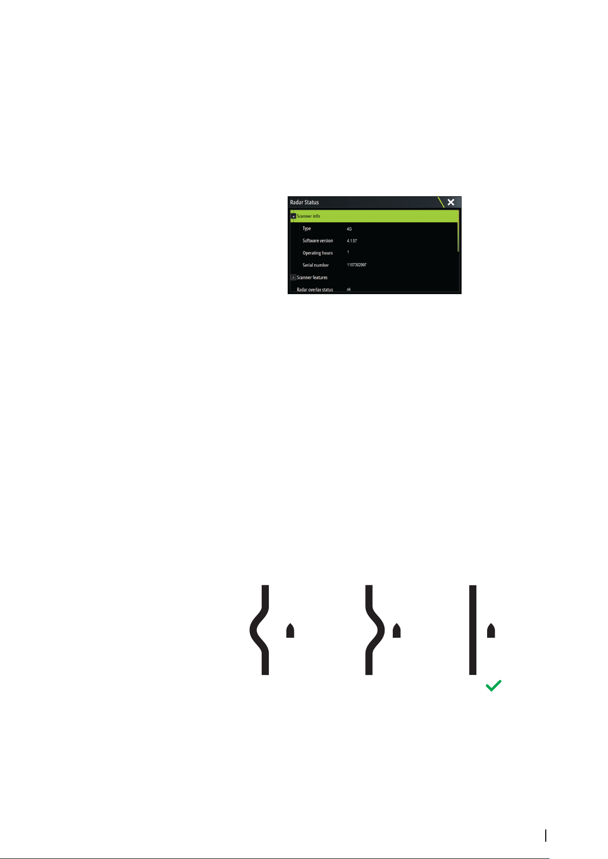
adjust the radar range offset to achieve this. If this is set incorrectly, a large dark circle in the
center of the sweep might occur. You might notice straight objects such as straight sea walls
or piers having curves or an indentation. Objects close to your vessel may appear pulled in or
pushed out.
Adjust the range offset as below when the vessel is about 45 to 90 m (50 to 100 yards) from a
straight-walled jetty or similar feature that produces a straight line echo on the display.
1 Position the vessel in relation to the jetty.
2 Adjust the range offset to make the jetty echo appear as a straight line on the
display.
Adjust bearing alignment
This option is used to align the heading marker on the screen with the center line of the
vessel. This will compensate for any slight misalignment of the scanner during installation.
Misalignment that is not corrected for will compromise target tracking and can result in
dangerous misinterpretation of potential navigation hazards.
Any inaccuracy will be evident when using MARPA or chart overlay.
System setup | Zeus³S Installation Manual
29
Page 30
1 Point the vessel towards a stationary isolated object, or towards a far range AIS
target where the AIS icon matches the radar echo.
2 Adjust the coarse and fine bearing alignment so that the heading line touches the
end of the selected object, or the radar target matches the AIS target.
Note: Adjustments to bearing alignment has to be done before Use mast rotation is
Ú
enabled.
Sidelobe suppression
Occasionally false target returns can occur adjacent to strong target returns such as large
ships or container ports. This occurs because not all of the transmitted radar energy can be
focused into a single beam by the radar antenna, a small amount of energy is transmitted in
other directions. This energy is referred to as sidelobe energy and occurs in all radar systems.
The returns caused by sidelobes tend to appear as arcs.
Note: This control should only be adjusted by experienced radar users. Target loss in
Ú
harbor environments may occur if this control is not adjusted correctly.
When the radar is mounted where there are metallic objects near the radar, sidelobe energy
increases because the beam focus is degraded. The increased sidelobe returns can be
eliminated using the sidelobe suppression control.
By default, this control is set to auto and normally should not need to be adjusted. However,
if there is significant metallic clutter around the radar, sidelobe suppression may need to be
increased.
To adjust the sidelobe suppression value:
1. Set radar range to between 1/2 nm to 1 nm and the sidelobe suppression to auto
2. Take the vessel to a location where sidelobe returns are likely to be seen. Typically, this
would be near a large ship, container port, or metal bridge.
3. Traverse the area until the strongest sidelobe returns are seen.
4. Change auto sidelobe suppression to OFF, then adjust the sidelobe suppression control
just enough to eliminate the sidelobe returns. You may need to monitor 5-10 radar
sweeps to be sure they have been eliminated.
5. Traverse the area again and readjust if sidelobes returns still occur.
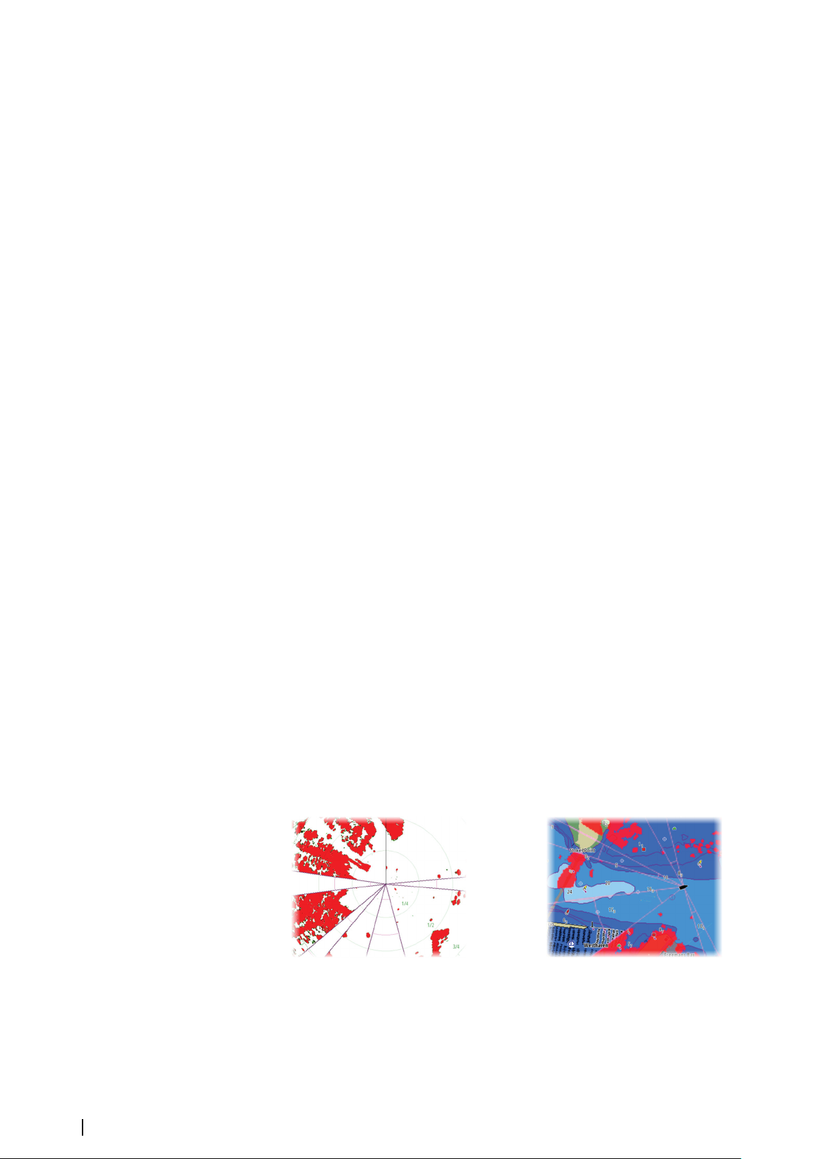
Sector blanking
Radar installed in close proximity to a mast or structure could cause unwanted reflections or
interference to appear on the radar image. Use the sector blanking feature to stop the radar
from transmitting on up to four sectors in the image.
Note: Sectors are setup relative to the heading line of the radar. The bearing of the
Ú
sector is measured from the center line of the sector.
Note: Sector blanking should be applied very carefully to avoid reducing the radar’s
Ú
usefulness in identifying valid and potentially dangerous targets.
Main radar PPI Radar overlay on a chart
Adjust open array park angle
The park angle is the final resting position of the antenna relative to the heading line of the
radar when the radar is set to standby. The antenna will stop rotating at the desired offset.
30
System setup | Zeus³S Installation Manual
Page 31
Adjust local interference reject
Interference from some onboard sources can interfere with the Broadband radar. One
symptom of this could be a large target on the screen that remains in the same relative
bearing even if the vessel changes direction.
Halo light
Controls the levels of the Halo Radar blue accent lighting. The accent lighting can only be
adjusted when the radar is in standby mode.
Note: The blue accent pedestal lighting might not be approved for use in your boating
Ú
location. Check your local boating regulations before turning the blue accent lights ON.
Tune
The automatic tuning will work well in most installations. The manual tuning is used if it is
required to adjust the result from an automatic tuning.
Reset radar to factory defaults
Clears all user and installer settings applied to the selected radar source, and restores factory
settings.
Note: Use this option with caution. Take note of current settings first, especially those set
Ú
by the operator if radar has already been in active service.
Echosounder settings
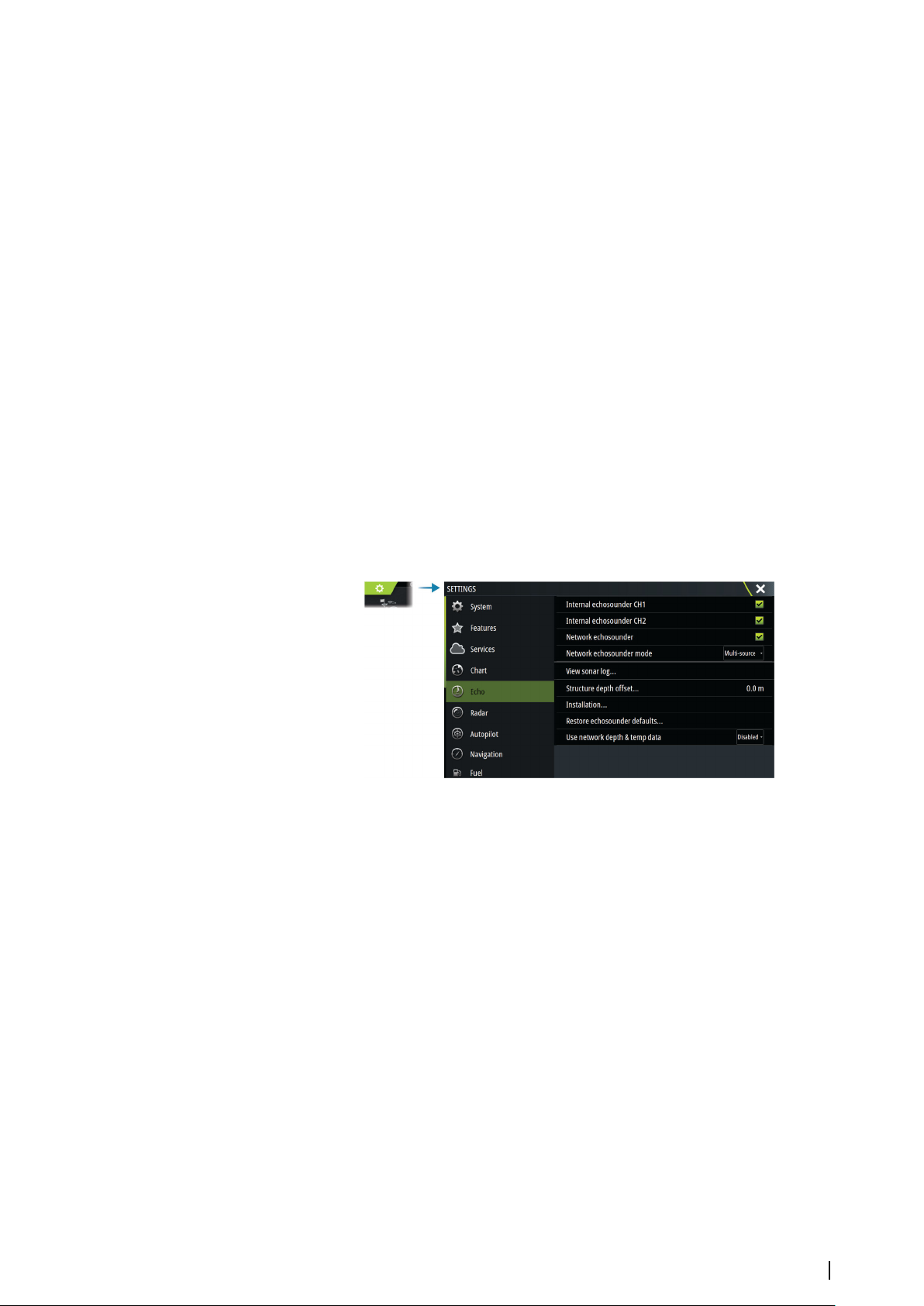
Internal echosounder CH1 and CH2
When selected, the internal echosounder channel is available for selection in the
echosounder panel menu.
When unselected, this option disables the internal echosounder channel in the unit. It will
not be listed as an echosounder source for any unit on the network. Unselect this option for
channels with no transducer connected.
Network Echosounder
Select to share transducers from this unit with other units connected on the Ethernet
network. In addition, the setting must be selected in order to see other enabled sonar
devices on the network.
When unselected, transducers connected to this unit cannot be shared with other units
connected on the network, nor can it see other sources on the network that have this feature
enabled.
Network echosounder mode
The network echosounder mode setting selects whether only one or multiple echosounder
sources can be selected at the same time.
Note: Single source is automatically selected if there are older legacy echosounders on
Ú
the network. You cannot change this setting if older legacy echosounders are on the
System setup | Zeus³S Installation Manual
31
Page 32
network. Multi-source mode should be selected if no legacy echosounder is connected
B
A
B
A
to the network.
Note: When changing the mode to multi-source you must wait 30 seconds and then
Ú
power down all sources for. Wait 1 minute, then restart all connected sources.
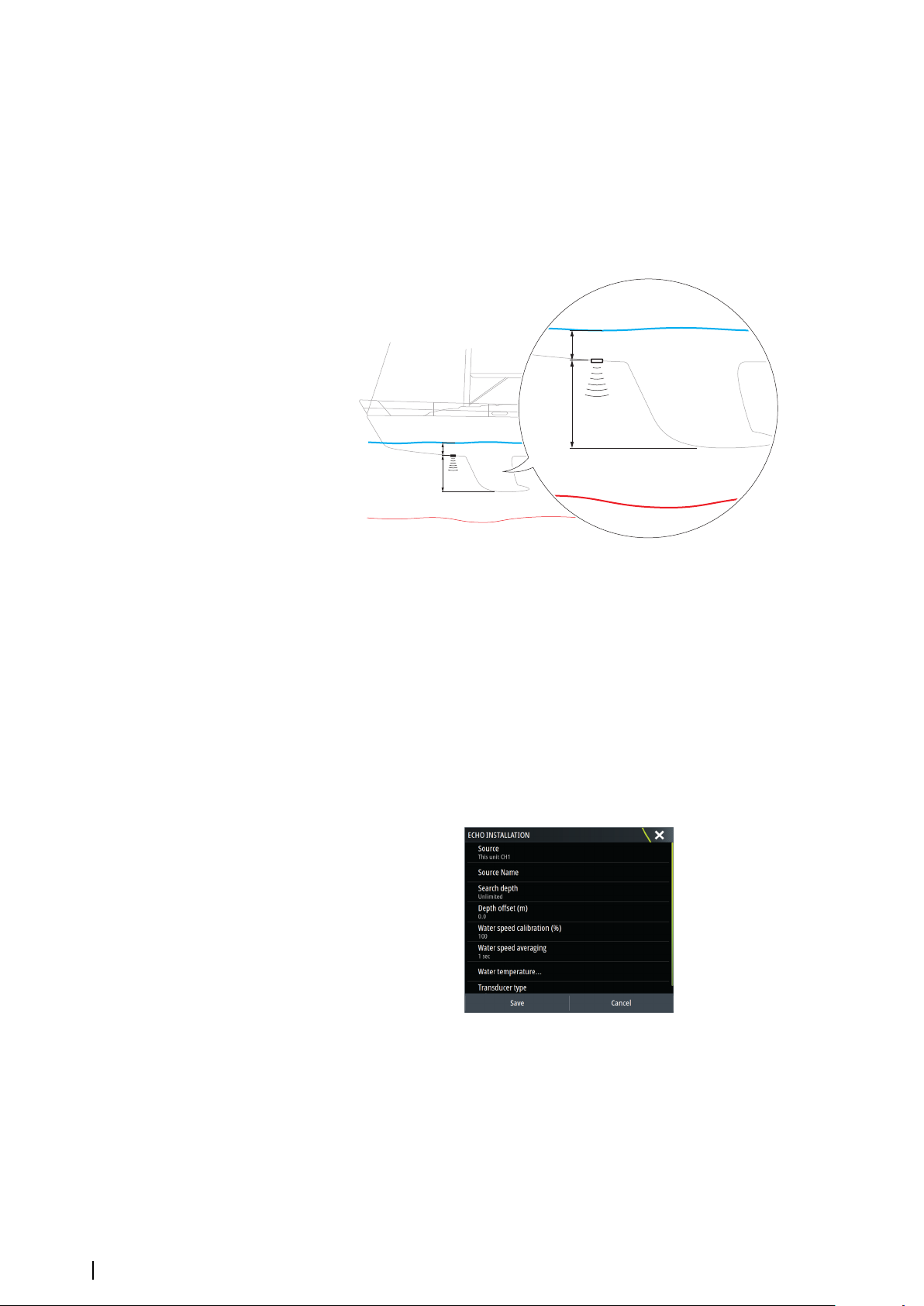
Structure depth offset
All transducers measure water depth from the transducer to the bottom. As a result, water
depth readings do not account for the distance from the transducer to the lowest point of
the boat in the water or from the transducer to the water surface.
• To show the depth from the lowest point of the vessel to the bottom, set the offset equal
to the vertical distance between the transducer and the lowest part of the vessel, A
(negative value).
• To show the depth from the water surface to the bottom, set the offset equal to the
vertical distance between the transducer and the water surface, B (positive value)
• For depth below transducer, set the offset to 0.
Use network depth and temp data
Selects from which network source depth and temperature data is shared on the NMEA 2000
network.
Installation
Use this dialog to setup and configure available sources.
Source
Select this option to display a list of sources available for setup. The settings you make in the
rest of the dialog pertain to the source selected.
Source name
Select this option to set a descriptive name for the selected transducer.
32
System setup | Zeus³S Installation Manual
Page 33
Search depth
B
A
B
A
Noise may cause the echosounder to search for unrealistic depths. By setting the search
depth manually the system displays echoes received from objects within the set depth
range.
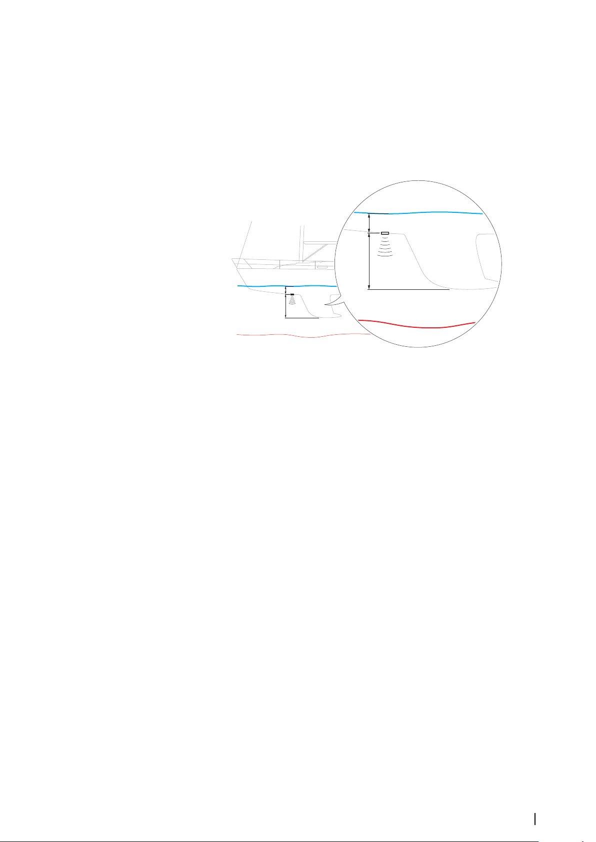
Depth offset
All transducers measure water depth from the transducer to the bottom. As a result, water
depth readings do not account for the distance from the transducer to the lowest point of
the boat in the water or from the transducer to the water surface.
• To show the depth from the lowest point of the vessel to the bottom, set the offset equal
to the vertical distance between the transducer and the lowest part of the vessel, A
(negative value).
• To show the depth from the water surface to the bottom, set the offset equal to the
vertical distance between the transducer and the water surface, B (positive value)
• For depth below transducer, set the offset to 0.
Water speed calibration
Water speed calibration is used to adjust the speed value from the paddle wheel to match
the actual boat speed through the water. Actual speed can be determined from GPS speed
over ground (SOG) or by timing the boat over a known distance. Water speed calibration
should be performed in calm conditions, with minimal wind and current movement.
Increase this value above 100 % if the paddle wheel is under reading, and decrease this value
if it is over reading. For example, if the average water speed reads 8.5 knots (9.8 MPH) and
SOG records 10 knots (11.5 MPH) the calibration value needs to be increased to 117 %. To
calculate the adjustment, divide the SOG by the paddlewheel speed, and multiply the
product by 100.
Calibration range: 50-200 %. Default is 100 %.
Water speed averaging
Averages water speed by measuring your speed at a selected interval of time. Water speed
intervals range from one to thirty seconds. For example if you select five seconds, your
displayed water speed will be based on averaging over 5 seconds of sampling.
Calibration range: 1-30 seconds. Default is 1 second.
Water temperature calibration
Temperature calibration is used to adjust the water temperature value from the sonar
transducer. It may be required to correct for localized influences to the measured
temperature.
Calibration range: -9.9° - +9.9°. Default is 0°.
Note: Water temperature calibration only appears if the transducer is temperature
Ú
capable.
System setup | Zeus³S Installation Manual
33
Page 34

Transducer type
Note: The transducer type is automatically set for transducers that support Transducer ID
Ú
(XID) and is not user selectable.
Transducer type is used for selecting the transducer model connected to the sonar module.
The transducer selected will determine what frequencies the user can select during sonar
operation. In some transducers with built-in temperature sensors, the temperature reading
may be inaccurate or not available at all if the wrong transducer is selected. Transducer
temperature sensors are one of two impedances - 5k or 10k. Where both options are given
for the same model transducer, refer to paperwork supplied with transducer to determine
impedance.
Restore echosounder defaults
Restore echosounder settings to the factory supplied defaults.
ForwardScan installation
Available when a ForwardScan transducer is connected.
For setup information, refer to the Operator Manual.
Autopilot settings
The Autopilot settings dialog depends on which autopilot computer that is connected to the
system. If more than one autopilot is connected, the Autopilot settings dialog shows option
for the active autopilot.
The autopilot settings can be split between settings done by the user, and settings done
during installation and commissioning of the autopilot system.
•
User settings can be changed for various operational conditions or user preferences.
• Installation settings are defined during commissioning of the autopilot system. No
changes should later be done to these settings.
The following sections describe the installation settings per autopilot computer. For user
settings, refer to the Operator manual.
H5000 specific installation settings
For setup and commissioning of the H5000, refer to the documentation included with the
H5000 system.
NAC-2/NAC-3 specific installation settings
For setup and commissioning of the NAC-2 or NAC-3, refer to the commissioning manual
included with the autopilot computer.
Fuel settings
The fuel utility monitors a vessel's fuel consumption. This information is totaled to indicate
trip and seasonal fuel usage, and is used to calculate fuel economy for display on instrument
pages and the data bar.
To use the utility, a Navico Fuel Flow sensor, or a NMEA 2000 engine adaptor cable/gateway
with Navico Fuel Data Storage device must be fitted to the vessel. The Navico Fuel Flow
sensor does not require the use of a separate Fuel Storage device. Refer to the engine
manufacturer or dealer for information on whether or not your engine provides a data
output, and what adaptor is available to connect to NMEA 2000.
Once the physical connection is made, ensure source selection is completed. Multiple engine
installations using Fuel Flow sensors, or Fuel Data Storage devices, require setup of related
engine location in the Device list. For general source selection information, refer to "Network
settings" on page 36.
34
System setup | Zeus³S Installation Manual
Page 35
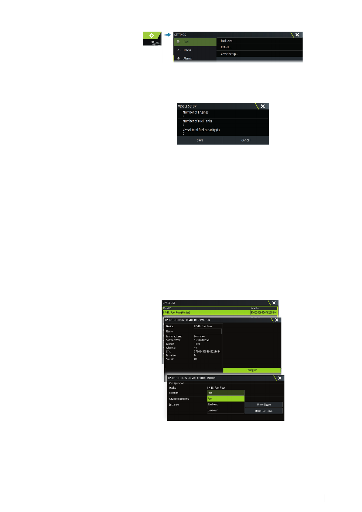
Vessel setup
The Vessel setup dialog must be used to select the number of engines, the number of tanks
and vessel’s total fuel capacity across all tanks.
Fuel remaining measurement
The Fuel remaining measurement can be determined from fuel used by engine(s), or fuel
level from tank sensors. Nominal fuel consumption is required to set the scale on the fuel
economy gauge. This value should be determined from experience, over time. Alternatively
the boat builder or designer may be able to give an approximate value to use.
Note: Fuel remaining measurement taken from level sensors while underway can get
Ú
inaccurate readings due to vessel movement.
Note: Nominal fuel consumption setting should be determined taking into account
Ú
typical vessel loads. That is, filled fuel and water tanks, stowed tender, supplies, etc.
Fuel flow configuration
After the number of engines is set, it is required to set which fuel flow sensor is connected to
which engine. Under Device list on the Network page, view the Device Configuration dialog
for each sensor, and set the Location to match the engine the device is connected to.
Unconfigure - defaults the device which clears all user settings.
Reset Fuel Flow - restores only the Fuel K-Value setting, if set in Calibrate. Only Navico
devices can be reset.
Calibrate
Calibration may be required to accurately match measured flow with actual fuel flow. Access
calibration from the Refuel dialog. Calibration is only possible on Navico’s Fuel Flow sensor.
1. Start with a full tank and run the engine as it would normally be operated.
System setup | Zeus³S Installation Manual
35
Page 36
2. After at least several liters (a few gallons) have been used, the tank should be fully refilled,
and the Set to full option selected.
3. Select the Calibrate option.
4. Set the actual amount used based on amount of fuel added to the tank.
5. Select OK to save settings. The Fuel K-Value should now show a new value.
Note: To calibrate multiple engines repeat the steps above, one engine at a time.
Ú
Alternatively, run all engines simultaneously, and divide the Actual amount used by the
number of engines. This assumes reasonably even fuel consumption on all engines.
Note: The Calibrate option is only available when Set to full is selected, and a Fuel Flow is
Ú
connected and set up as a source.
Note: A maximum of 8 engines is supported using Fuel Flow sensors.
Ú
Fuel Level
With the use of a Navico Fluid Level device connected to a suitable tank level sensor, it is
possible to measure the amount of fuel remaining in any equipped tank. The number of
tanks must be set in Vessel Setup dialog, initiated from the Fuel setting options page, to
allow discrete tank assignment of the Fluid Level devices.
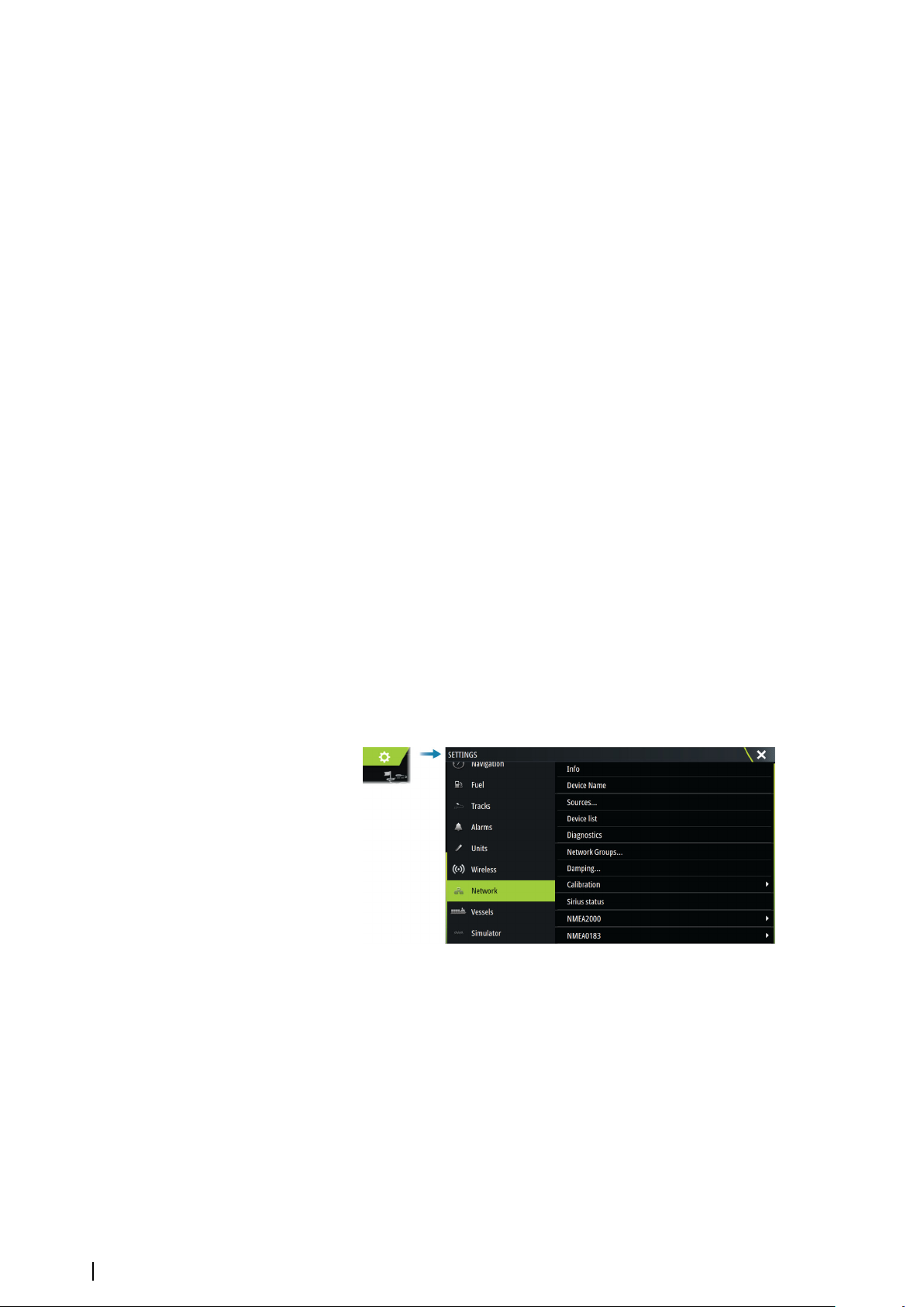
Select Device list on the Network page, and view the Device Configuration dialog for each
sensor, and set the Tank location, Fluid type, and Tank size.
For setting up the Instrument bar or a gauge on the Instrument page with Fluid Level device
data, refer to the Operator Manual.
Note: A maximum of 5 tanks is supported using Fluid Level devices.
Ú
Note: Tank data that is output by a compatible engine gateway can also be displayed,
Ú
however tank configuration for such a data source is not possible from this unit.
Wireless settings
Provides configuration and setup options for the wireless functionality.
For further details about wireless setup and connectivity, refer to the Operator Manual.
Network settings
Device name
Assigning a name is useful in systems using more than one device of the same type and size.
36
Sources
Data sources provide live data to the system.
When a device is connected to more than one source providing the same data, the user can
choose the preferred source. Before commencing with source selection make sure all
external devices and networks are connected and turned on.
System setup | Zeus³S Installation Manual
Page 37
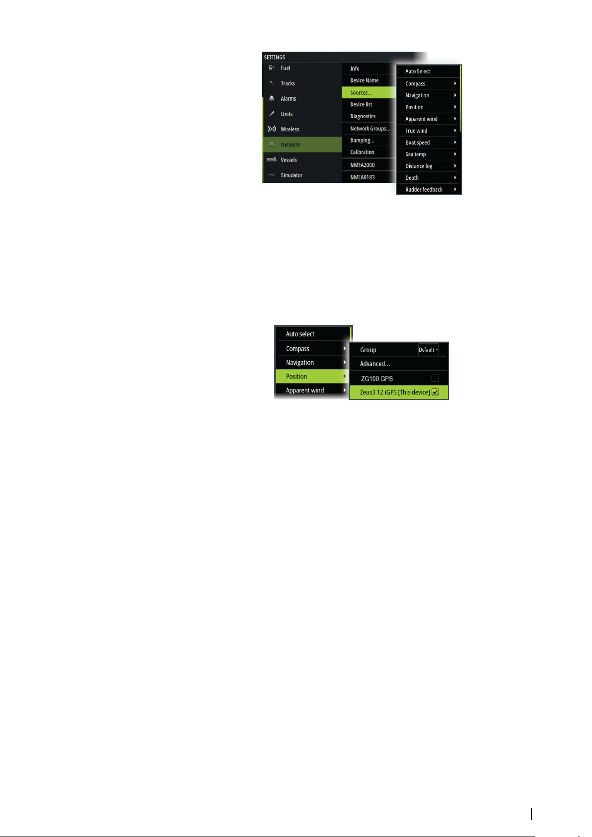
Auto Select
The Auto Select option looks for all sources connected to the device. If more than one source
is available for each data type, selection is made from an internal priority list. This option is
suitable for the majority of installations.
Manual source selection
Manual selection is generally only required where there is more than one source for the same
data, and the automatically selected source is not the one desired.
Group source selection
The unit can use the same data sources that all other products on the network use, or
alternatively use a data source independently from other units.
If the unit is part of a source group, all source selection changes will affect all units belonging
to the same group.
Note: In order to enable group selection, the unit must be set to the Default group.
Ú
Devices with no selected group can use different sources than the rest of the network
devices.
Advanced source selection
This allows the most flexible and precise manual control over which devices provide data.
Occasionally auto select might not assign the desired source, which can be corrected using
the advanced source selection.
Device list
Selecting a device in this list will bring up additional details and options for the device.
All devices allow allocation of an instance number in the configure option. Set unique
instance numbers on any identical devices on the network to allow the unit to distinguish
between them. The data option shows all data being output by the device.
Note: In most cases, setting the instance number on a 3rd party product is not possible.
Ú
Diagnostics
Provides information useful for identifying an issue with the network.
NMEA 2000
Provides information on NMEA 2000-bus activity.
System setup | Zeus³S Installation Manual
37
Page 38

Note: The following information might not always indicate an issue that can be simply
Ú
resolved with minor adjustment to network layout or connected devices and their
activity on the network. However, Rx and Tx errors are most likely indicating issues with
the physical network, which can be resolved by correcting termination, reducing
backbone or drop lengths, or reducing the number of network nodes (devices).
UDB
Provides information on Ethernet activity.
Network groups
This function is used to control parameter settings, either globally or in groups of units. The
function is used on larger vessels where several units are connected via a network. By
assigning several units to the same group, a parameter update on one unit will have the
same effect on the rest of the group members.
If any of the settings require discrete control, set the group to None.
Damping
If data appears erratic or too sensitive, damping may be applied to make the information
appear more stable. With damping set to off, the data is presented in raw form with no
damping applied.
Calibration
An offset (positive or negative) can be applied to correct data inaccuracies from NMEA 2000
sources. The offset is set on the NMEA 2000 device.
Note: Select the advanced option to adjust local offsets for this display only.
Ú
Note: It is typically not possible to calibrate 3rd party sensors. However, a local offset can
Ú
be applied.
NMEA 2000 setup
Receive waypoint
Select this option to allow another device capable of creating and exporting waypoints via
NMEA 2000 to transfer directly to this unit.
Send waypoint
Select this option to allow this unit to send waypoints to another device via NMEA 2000.
Note: The system can only transmit or receive one waypoint at a time on creation of that
Ú
waypoint. For bulk import or export of waypoints see the operator manual.
NMEA 0183 setup
The NMEA 0183 port(s) must be set to suit the speed of connected devices, and can be
configured to output only the sentences required by listening devices.
Receive waypoint
Select this option to allow a device capable of creating and exporting waypoints via NMEA
0183 to transfer directly to this unit.
38
Baud rate
This should be set to correspond with devices connected to the NMEA 0183 input and
output. The input and output (Tx, Rx) use the same baud rate setting.
Note: AIS transponders typically operate at NMEA 0183-HS (high speed), and will require
Ú
the baud rate to be set to 38,400.
System setup | Zeus³S Installation Manual
Page 39

Serial output
Selection determines whether the data is output via Tx lines, and will enable editing of the
output sentences list.
Serial output sentences
This list allows control over which sentences that are transmitted to other devices from the
NMEA 0183 port. Due to the limited bandwidth of NMEA 0183 it is desirable to only enable
the data that is required. The less sentences that are selected, the higher the output rate of
the enabled sentences.
Ethernet/WiFi
The NMEA 0183 data stream is output and made available to tablet devices and PCs, via WiFi
or Ethernet connection. The dialogue provides IP and port data typically required for
configuring the application on the third party device.
Note: Other MFDs cannot decode this information back to NMEA 0183, to use the data
Ú
as a source. To share data a physical NMEA 2000 or NMEA 0183 connection is still
required.
System setup | Zeus³S Installation Manual
39
Page 40
3rd party support
NETWORK INTERFACE
Network 1 Network 2
CZONE
NETWORK
67$786
5HG1HWZRUN
*UHHQ1HWZRUN
CZONE
NMEA2000
5
CZone
CZone connection to NMEA 2000
When interfacing to CZone network it is recommended to use a BEP Network interface
bridge to join the two network backbones together.
The CZone / NMEA 2000 Network interface bridge isolates the power of the two networks,
but allows data to be freely shared between both sides.
The Interface Bridge can also be used for expansion of the NMEA 2000 network, when the
maximum node limit (node = any device connected to network) for the network has been
reached or the maximum cable length of 150 m will be exceeded. Once an Interface Bridge
has been fitted, a further 40 nodes and additional cable length can be added.
The Network Interface is available from your BEP dealer. For more information please refer to
the BEP web site www.bepmarine.com.
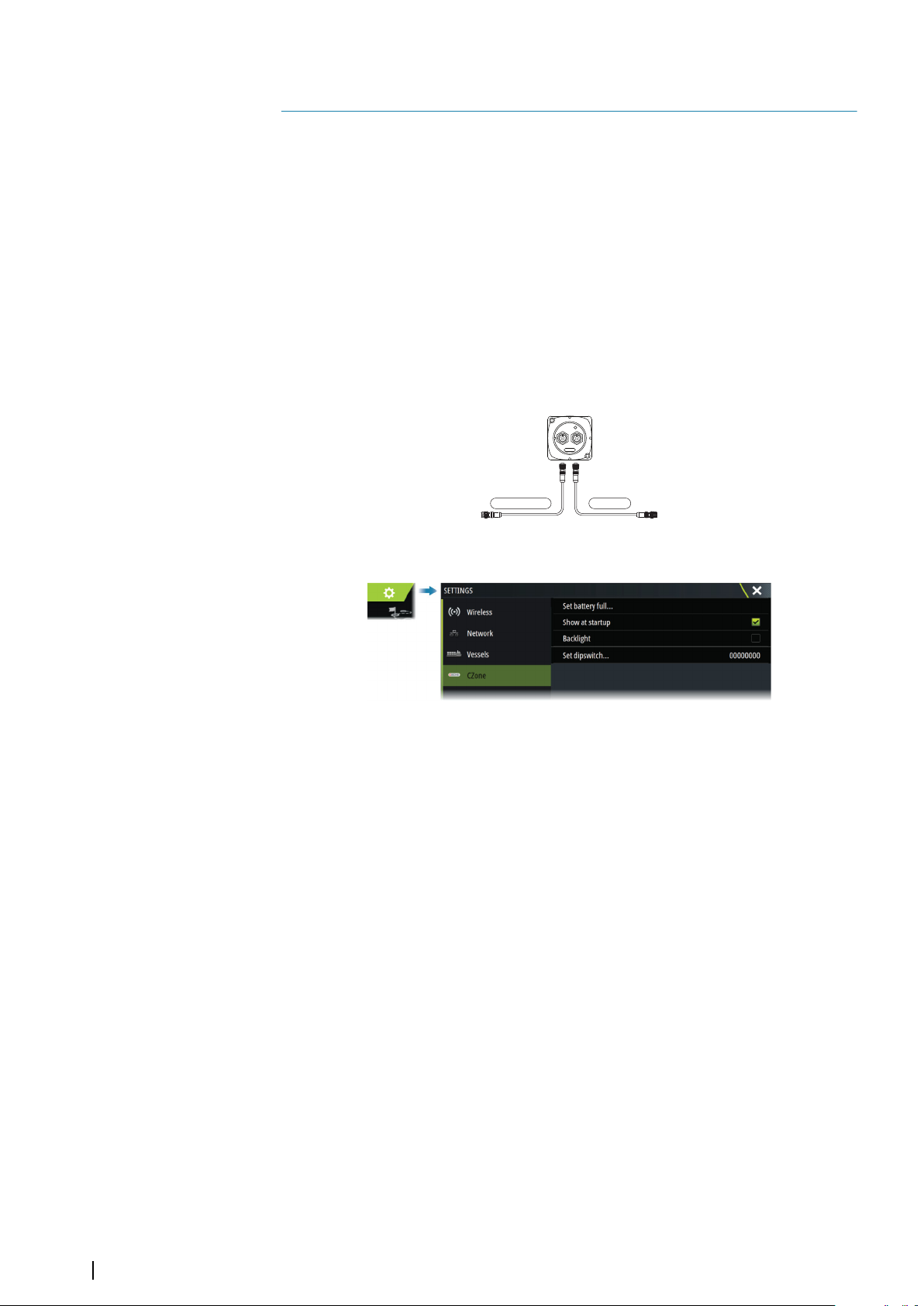
CZone setup
In order to communicate with the CZone modules connected to the network, the unit must
be assigned a unique CZone Display Dipswitch setting.
The functionality of the CZone system is determined by the CZone Config File which is
stored on all CZone modules and the Zeus³S. The file is created using the CZone
Configuration Tool, a specialized PC application available from BEP Marine Ltd, and
associated CZone distributors.
For more information, refer to the documentation provided with your CZone system.
Assigning the dipswitch setting
Every product capable of controlling and viewing CZone devices must be assigned a virtual
dipswitch setting. This setting is unique for each device. Typically it is set after the
configuration file already exists on the CZone system, but it may also be set in advance. To
do so, access the CZone menu on the Settings page.
When the configuration is already available on the network, it will immediately commence
uploading to the Zeus³S once the dipswitch is set. Allow this to complete, without
interruption.
Setting CZone to display at startup
With this option selected, the CZone control page is shown first, every time the Zeus³S is
powered up.
Backlight
Enabling this causes the Zeus³S to synchronize its backlight setting with that of any CZone
Display Interfaces set up to share backlight settings.
40
Note: CZone Config also needs to have the Zeus³S set as a controller.
Ú
3rd party support | Zeus³S Installation Manual
Page 41
Naviop
If this device is on the same NMEA 2000 network as a Naviop Loop system, this device can be
used to operate the Naviop Loop system.
For details, refer to the documentation following the Naviop system.
FLIR camera setup
Compatible FLIR cameras are plug and play when used in conjunction with a device acting
as a DHCP host. For setup on networks not utilizing a DHCP host, refer to the website
www.bandg.com, or contact technical support.
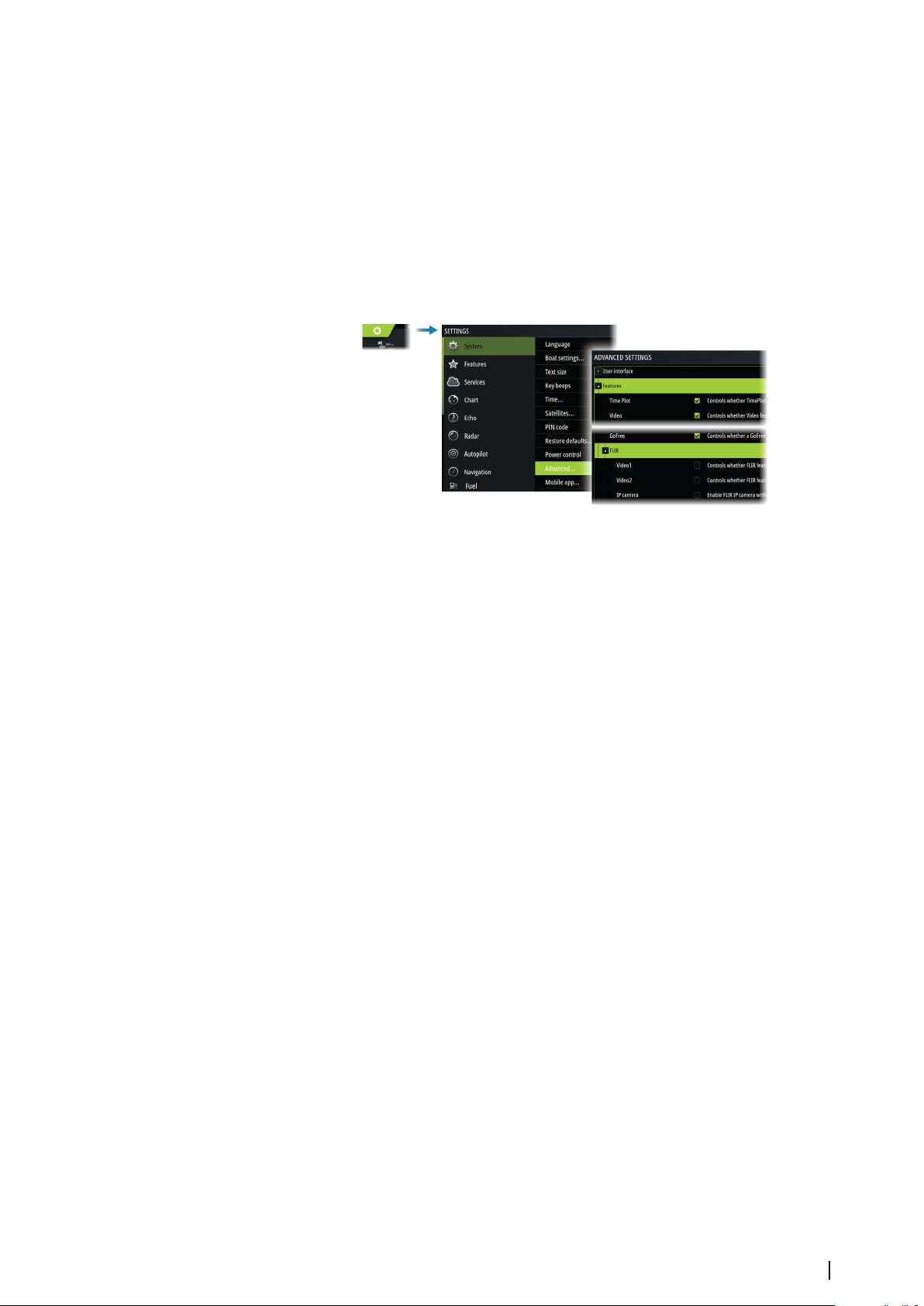
FLIR settings can be found in the advanced settings dialog.
3rd party support | Zeus³S Installation Manual
41
Page 42

Appendix
6
Technical specifications
Technical specifications
Display
Resolution
9" unit 1280 x 720
12" unit 1280 x 800
16" unit 1920 x 1080
Type High Visibility SolarMax HD® IPS optically
bonded TFT
Brightness 1200 nits
Touch screen Full touch screen (multi-touch)
Viewing angles in degrees (typical value @
contrast ratio = 10)
Electrical
Supply voltage 12/24 V DC (10 - 31.2 V DC min - max)
Power consumption - Max
9" unit 23 W +- 4 W
12" unit 30 W +- 5 W
16" unit 45 W +- 5 W
Recommended fuse rating
9" unit 5 A
12" unit 5 A
16" unit 5 A
Environmental
Operating temperature range -15°C to +55°C (5°F to 131°F)
Storage temperature -20°C to +60°C (4°F to 140°F)
Waterproof rating IPX 6 and 7
Humidity IEC 60945 Damp heat 66°C (150°F) at 95%
Shock and vibration 100 000 cycles of 20 G
Position Built-in 10 Hz GNSS receiver for GPS and
Interface/Connectivity
Ethernet
9" unit 1 port (5-pin connector)
12" and 16" units 2 ports (5-pin connector)
NMEA 2000 1 port (Micro-C)
NMEA 0183 1 talker/listener (4800, 9600, 19200, 38400
Sonar 2 ports
Video input 2 ports (Composite video RCA - via optional
80° top/bottom, 80° left/right
relative (48 hr)
GLONASS, supports combinations with
Galileo, Beidou, QZSS.
SBAS (WAAS, EGNOS, MSAS, GAGAN).
baud - via optional adaptor cable)
adaptor cable)
42
Appendix | Zeus³S Installation Manual
Page 43

Video output
9" unit Not applicable
12" and 16" units 1 port (HDMI 1.4 sink and HDCP)
Data card reader 2 slots (microSD, max 32 GB, FAT32)
Wireless 802.11b/g/n
Bluetooth Bluetooth 4.0 with support for Bluetooth
Classic
USB
9" and 12" units Not applicable
16" unit 1 port (USB A)
Output: 5 V DC, 1.5 A
Physical
Dimensions (W x H x D) Refer to "Dimensional drawings" on page 44
Weight (display only)
9" unit 1.4 kg (3.11 lbs.)
12" unit 3.1 kg (6.83 lbs.)
16" unit 4.7 kg (10.25 lbs.)
Compass Safe Distance - Metric, imperial 50 cm (1.7 ft)
Mounting type Bracket (Supplied) or panel mount
Appendix | Zeus³S Installation Manual
43
Page 44
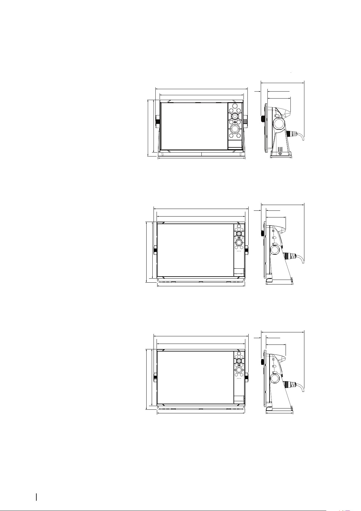
Dimensional drawings
310.9 mm (12.24”)
287.0 mm (11.30”)
179.5 mm (7.07”)
166.3 mm (6.55”)
131.0 mm (5.15”)
(2.74”)
18.5 mm (0.73”)
69.6 mm
66.6 mm (2.62”)
296.2 mm (11.66”)
377.1 mm (14.85”)
351.5 mm (13.84”)
240.6 mm (9.47”)
170.3 mm (6.70”)
78.1 mm
(3.07”)
225.3 mm (8.87”)
18.5 mm (0.73”)
349.0 mm (13.74”)
106.7 mm (4.20”)
462.1 mm (18.19”)
436.5 mm (17.19”)
263.9 mm (10.39”)
170.3 mm (6.70”)
79.6 mm
256.0 mm (10.08”)
434.0 mm (17.09”)
18.5 mm (0.73 ”)
(3.13”)
106.8 mm (4.21”)
9" unit
12" unit
44
16" unit
Appendix | Zeus³S Installation Manual
Page 45

Supported data
NMEA 2000 compliant PGN List
NMEA 2000 PGN (receive)
59392 ISO Acknowledgement
59904 ISO Request
60160 ISO Transport Protocol, Data Transfer
60416 ISO Transport Protocol, Connection M.
65240 ISO Commanded Address
60928 ISO Address Claim
126208 ISO Command Group Function
126992 System Time
126996 Product Info
126998 Configuration Information
127233 Man Overboard Notification (MOB)
127237 Heading/Track Control
127245 Rudder
127250 Vessel Heading
127251 Rate of Turn
127252 Heave
127257 Attitude
127258 Magnetic Variation
127488 Engine Parameters, Rapid Update
127489 Engine Parameters, Dynamic
127493 Transmission Parameters, Dynamic
127500 Load Controller Connection State / Control
127501 Binary Status Report
127503 AC input status
127504 AC Output Status
127505 Fluid Level
127506 DC Detailed Status
127507 Charger Status
127508 Battery Status
127509 Inverter Status
128259 Speed, Water referenced
128267 Water Depth
128275 Distance Log
129025 Position, Rapid Update
129026 COG & SOG, Rapid Update
129029 GNSS Position Data
129033 Time & Date
129038 AIS Class A Position Report
129039 AIS Class B Position Report
129040 AIS Class B Extended Position Report
129041 AIS aids to Navigation
Appendix | Zeus³S Installation Manual
45
Page 46

129283 Cross Track Error
129284 Navigation Data
129539 GNSS DOPs
129540 AIS Class B Extended Position Report
129545 GNSS RAIM Output
129549 DGNSS Corrections
129551 GNSS Differential Correction Receiver Signal
129793 AIS UTC and Date Report
129794 AIS aids to Navigation
129798 AIS SAR Aircraft Position Report
129801 Cross Track Error
129802 AIS Safety Related Broadcast Message
129283 Cross Track Error
129284 Navigation Data
129539 GNSS DOPs
129540 GNSS Sats in View
129794 AIS Class A Static and Voyage Related Data
129801 AIS Addressed Safety Related Message
129802 AIS Safety Related Broadcast Message
129808 DSC Call Information
129809 AIS Class B “CS” Static Data Report, Part A
129810 AIS Class B “CS” Static Data Report, Part B
130060 Label
130074 Route and WP Service - WP List - WP Name & Position
130306 Wind Data
130310 Environmental Parameters
130311 Environmental Parameters
130312 Temperature
130313 Humidity
130314 Actual Pressure
130316 Temperature, Extended Range
130569 Entertainment - Current File and Status
130570 Entertainment - Library Data File
130571 Entertainment - Library Data Group
130572 Entertainment - Library Data Search
130573 Entertainment - Supported Source Data
130574 Entertainment - Supported Zone Data
130576 Small Craft Status
130577 Direction Data
130578 Vessel Speed Components
130579 Entertainment - System Configuration Status
130580 Entertainment - System Configuration Status
130581 Entertainment - Zone Configuration Status
130582 Entertainment - Zone Volume Status
130583 Entertainment - Available Audio EQ Presets
130584 Entertainment - Bluetooth Devices
46
Appendix | Zeus³S Installation Manual
Page 47

130585 Entertainment - Bluetooth Source Status
NMEA 2000 PGN (transmit)
60160 ISO Transport Protocol, Data Transfer
60416 ISO Transport Protocol, Connection M.
126208 ISO Command Group Function
126992 System Time
126993 Heartbeat
126996 Product Info
127237 Heading/Track Control
127250 Vessel Heading
127258 Magnetic Variation
127502 Switch Bank Control
128259 Speed, Water referenced
128267 Water Depth
128275 Distance Log
129025 Position, Rapid Update
129026 COG & SOG, Rapid Update
129029 GNSS Position Data
129283 Cross Track Error
129285 Navigation - Route/WP Information
129284 Navigation Data
129285 Route/Waypoint Data
129539 GNSS DOPs
129540 GNSS Sats in View
130074 Route and WP Service - WP List - WP Name & Position
130306 Wind Data
130310 Environmental Parameters
130311 Environmental Parameters
130312 Temperature
130577 Direction Data
130578 Vessel Speed Components
Appendix | Zeus³S Installation Manual
47
Page 48
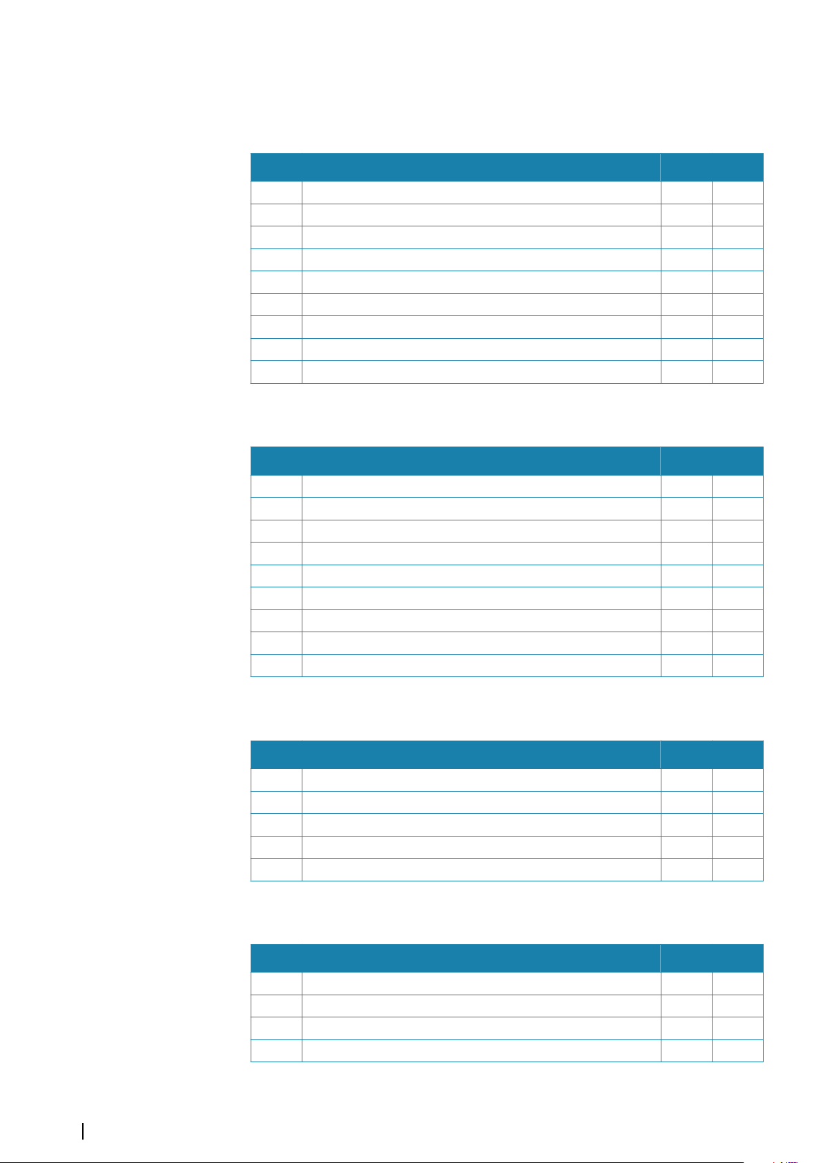
NMEA 0183 supported sentences
TX / RX - GPS
Name Description RX TX
DTM Datum reference x
GGA Global positioning system (GPS) fix data x x
GLC Geographic position - Loran-C
GLL Geograpic position - Latitude/longitude x x
GSA GNSS DOP and active satellites x x
GNS GNSS fix data x
GSV GNSS satellites in view x x
VTG Course over ground and ground speed x x
ZDA Time and date x x
TX / RX - Navigation
Name Description RX TX
AAM Waypoint arrival alarm x
APB Heading/track controller (autopilot) sentence B x
BOD Bearing origin to destination x
BWC Bearing and distance to waypoint - Great circle x
BWR Bearing and distance to waypoint - Rhumb line x
RMB Recommended minimum navigation information x
XTE Cross-track error - measured x
RTE Routes x
WPL Waypoint location x
TX / RX - Sonar
Name Description RX TX
DBT Depth below transducer x x
DPT Depth x x
MTW Water temperature x x
VLW Dual ground/water distance x x
VHW Water speed and heading x x
TX / RX - Compass
Name Description RX TX
HDG Heading, deviation and variation x x
HDT Heading true x
THS True heading and status x x
ROT Rate of turn x
48
Appendix | Zeus³S Installation Manual
Page 49
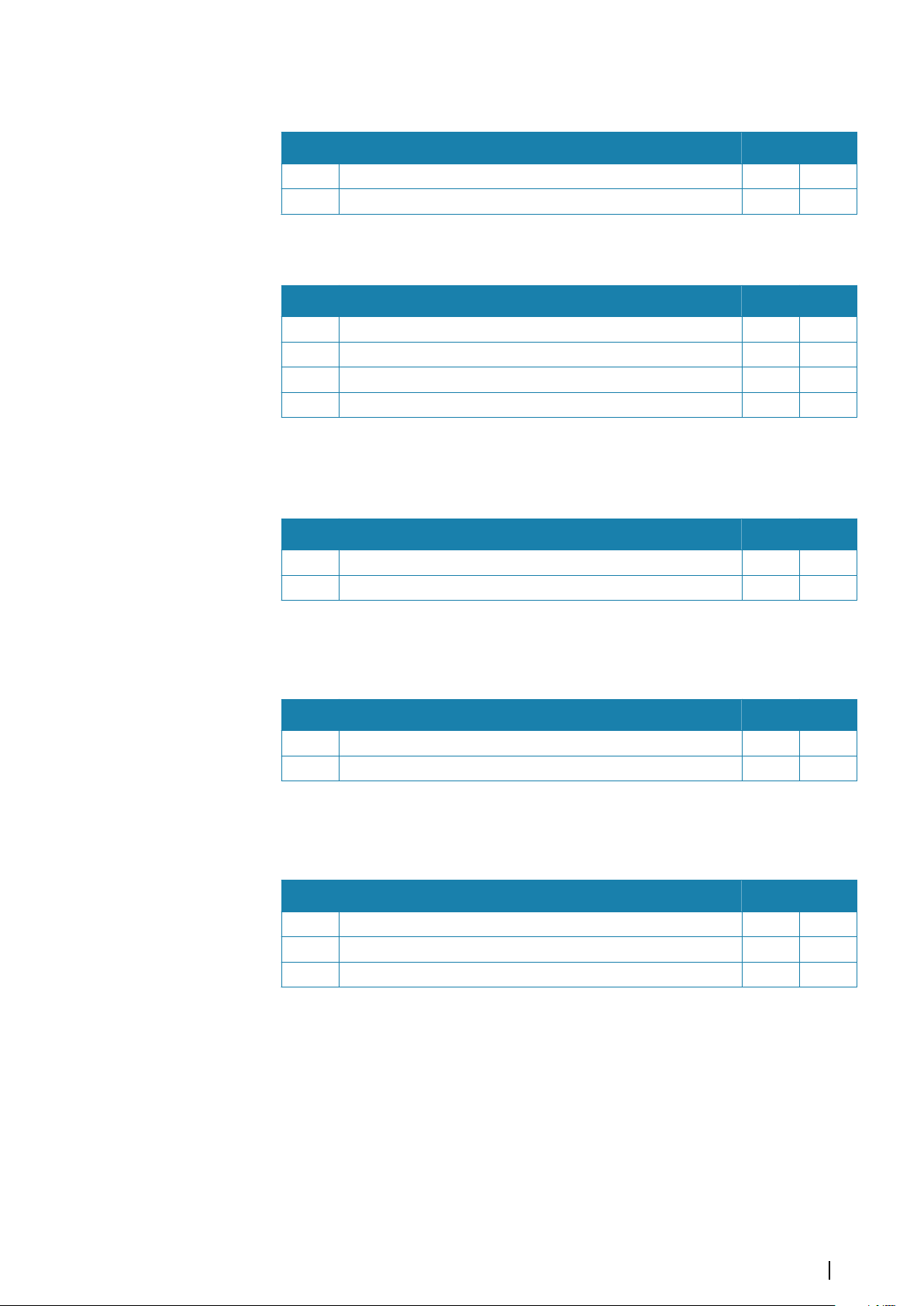
TX / RX - Wind
Name Description RX TX
MWD Wind direction and speed x x
MWV Wind speed and angle x x
TX / RX - AIS / DSC
Name Description RX TX
DSC Digital selective calling information x
DSE Expanded digital selective calling x
VDM AIS VHF data-link message x
VDO AIS VHF data-link own-vessel report x
Note: AIS sentences are not bridged to or from NMEA 2000.
Ú
TX / RX - MARPA
Name Description RX TX
TLL Target latitude and longitude x
TTM Tracked target message x
Note: These are only output sentences.
Ú
Radar
Name Description RX TX
RSD Radar system data *x
OSD Own ship data *x
Note: *x - only transmitting when the radar panel is displayed.
Ú
MISC
Name Description RX TX
MOB Man over board notification x
VBW Dual ground/water speed x
XDR Transducer measurement x x
Appendix | Zeus³S Installation Manual
49
Page 50

Page 51

*988-12599-001*
 Loading...