

Page 1
Zeus3S
Operator Manual
ENGLISH
www.bandg.com
Page 2

Page 3

Preface
Disclaimer
As Navico is continuously improving this product, we retain the right to make changes to the
product at any time which may not be reflected in this version of the manual. Please contact
your nearest distributor if you require any further assistance.
It is the owner’s sole responsibility to install and use the equipment in a manner that will not
cause accidents, personal injury or property damage. The user of this product is solely
responsible for observing maritime safety practices.
NAVICO HOLDING AS AND ITS SUBSIDIARIES, BRANCHES AND AFFILIATES DISCLAIM ALL
LIABILITY FOR ANY USE OF THIS PRODUCT IN A WAY THAT MAY CAUSE ACCIDENTS, DAMAGE
OR THAT MAY VIOLATE THE LAW.
This manual represents the product as at the time of printing. Navico Holding AS and its
subsidiaries, branches and affiliates reserve the right to make changes to specifications
without notice.
Governing language
This statement, any instruction manuals, user guides and other information relating to the
product (Documentation) may be translated to, or has been translated from, another
language (Translation). In the event of any conflict between any Translation of the
Documentation, the English language version of the Documentation will be the official
version of the Documentation.
Trademarks
Navico® is a registered trademark of Navico Holding AS.
B&G® is a registered trademark of Navico Holding AS.
Bluetooth® is a registered trademark of Bluetooth SIG, Inc.
C-MAP® is a registered trademark of Navico Holding AS.
CZone™ is a trademark of Power Products LLC.
FLIR® is a registered trademark of FLIR.
FUSION-Link™ Marine Entertainment Standard™ is a registered trademark of FUSION
Electronics Ltd.
Navionics® is a registered trademark of Navionics, Inc.
NMEA® and NMEA 2000® are registered trademarks of the National Marine Electronics
Association.
SD™ and microSD™ are trademarks or registered trademarks of SD-3C, LLC in the United
States, other countries or both.
SiriusXM® is a registered trademark of Sirius XM Radio Inc.
Navico product references
This manual refers to the following Navico products:
• Broadband Radar™ (Broadband Radar)
• Broadband 3G™ (Broadband 3G Radar)
• Broadband 4G™ (Broadband 4G Radar)
• DownScan Overlay™ (Overlay)
• ForwardScan™ (ForwardScan)
• Genesis® (Genesis)
• Halo™ Pulse Compression Radar (Halo Radar)
Copyright
Copyright © 2020 Navico Holding AS.
Warranty
The warranty card is supplied as a separate document. In case of any queries, refer to the
brand website of your unit or system:
Preface | Zeus³S Operation Manual
3
Page 4
www.bandg.com
Compliance statements
Declarations
The relevant declaration of conformity is available in the product's section at the following
website:
www.bandg.com
Europe
Navico declare under our sole responsibility that the product conforms with the
requirements of:
• CE under RED 2014/53/EU
United States of America
Navico declare under our sole responsibility that the product conforms with the
requirements of:
• Part 15 of the FCC Rules. Operation is subject to the following two conditions: (1) this
device may not cause harmful interference, and (2) this device must accept any
interference received, including interference that may cause undesired operation
Warning: The user is cautioned that any changes or modifications not
expressly approved by the party responsible for compliance could void the
user’s authority to operate the equipment.
Note: This equipment generates, uses and can radiate radio frequency energy and, if not
Ú
installed and used in accordance with the instructions, may cause harmful interference
to radio communications. However, there is no guarantee that the interference will not
occur in a particular installation. If this equipment does cause harmful interference to
radio or television reception, which can be determined by turning the equipment off
and on, the user is encouraged to try to correct the interference by one or more of the
following measures:
• Reorient or relocate the receiving antenna
• Increase the separation between the equipment and receiver
• Connect the equipment into an outlet on a circuit different from that of the receiver is
connected
• Consult the dealer or an experienced technician for help
ISED Canada
This device complies with ISED (Innovation, Science and Economic Development) Canada’s
license-exempt RSSs. Operation is subject to the following two conditions: (1) This device
may not cause interference; and (2) This device must accept any interference, including
interference that may cause undesired operation of the device.
La traduction française de ce document est disponible sur le site Web du produit.
Australia and New Zealand
Navico declare under our sole responsibility that the product conforms with the
requirements of:
• level 2 devices of the Radiocommunications (Electromagnetic Compatibility) standard
2017
• radiocommunications (Short Range Devices) Standards 2014
About this manual
This manual is a reference guide for operating the unit. It assumes that all equipment is
installed and configured, and that the system is ready to use.
4
Preface | Zeus³S Operation Manual
Page 5
Images used in this manual might not exactly match the screen on your unit.
Important text conventions
Important text that requires special attention from the reader is emphasized as follows:
Note: Used to draw the reader’s attention to a comment or some important information.
Ú
Warning: Used when it is necessary to warn personnel that they should
proceed carefully to prevent risk of injury and/or damage to equipment/
personnel.
Manual version
This manual is written for software version 19.3. The manual is continually updated to match
new software releases. The latest available manual version can be downloaded from the
following website:
• www.bandg.com
Translated manuals
Available translated versions of this manual can be found on the following website:
• www.bandg.com
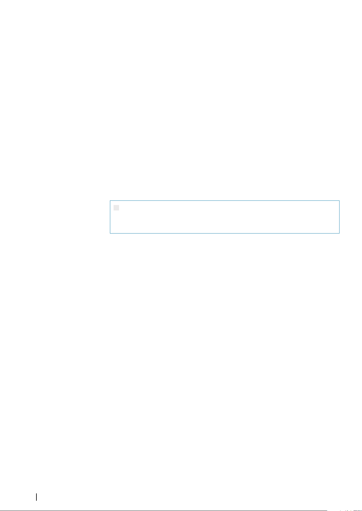
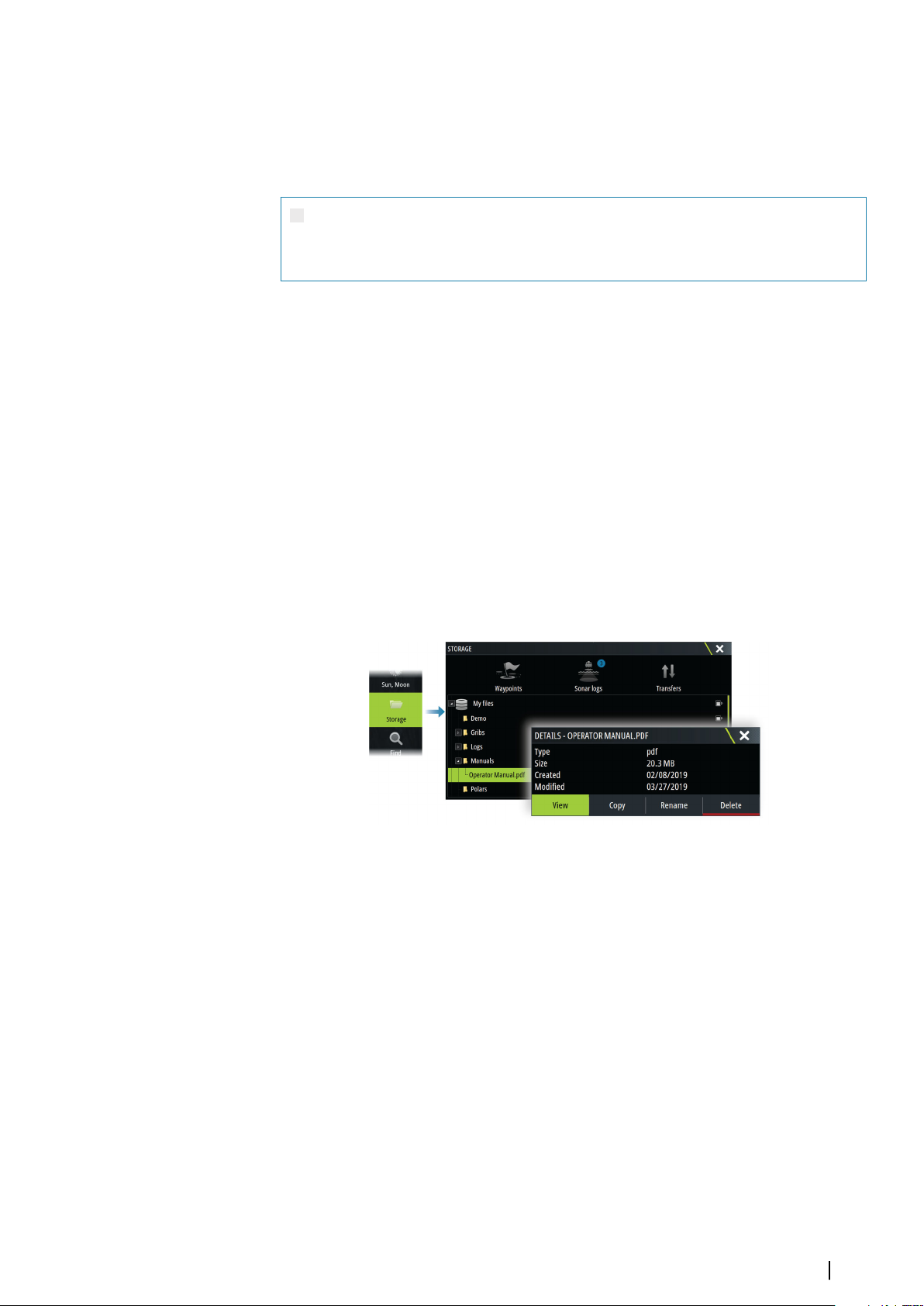
Viewing the manual on the screen
The PDF viewer included in the unit makes it possible to read the manuals and other PDF
files on the screen.
The manuals can be read from a storage device connected to the unit or copied to the unit’s
internal memory.
Device registration
You are prompted to register your device during startup. You can also register it by following
the instructions when selecting the registration option in the system settings dialog or
system controls dialog.
Preface | Zeus³S Operation Manual
5
Page 6

Contents
11 Introduction
11
Front controls
12 Card reader
12 Home page
14 Application pages
16 Basic operation
16 Turning the system on and off
16 Touchscreen, keyboard and mouse operation
16 Remote controllers
16 System controls dialog
17 Screen capture
18 Customizing your system
18 Customizing the Home page wallpaper
18 Configurable WheelKey
18 Customizing the long press feature
18 Multiple panel pages
19 Customizing favorite pages
19 Customizing the instrument bar
20 Adjusting the split on multiple panel pages
20 Enabling or disabling features
20 Activating/deactivating features and applications
21 Password Protection
21 H5000 integration
22 Charts
22 The Chart panel
22 Chart data
22 Selecting chart source
22 Showing dual chart sources
22 Vessel symbol
23 Zooming the chart
23 Panning the chart
23 Chart orientation
23 Look ahead
23 Displaying information about chart items
24 Using the cursor on the panel
24 Measuring distance
25 Creating routes on the chart panel
25 Find objects on chart panels
25 3D charts
25 Tracks
25 Color tracks based on data
26 Chart overlay
27 PredictWind weather and routing
27 C-MAP charts
29 Navionics charts
32 Chart settings
36 Waypoints, routes, and tracks
36 Waypoints, Routes, and Tracks dialogs
36 The Plot dialog
36 Waypoints
37 Routes
41 Tracks
42 C-MAP Embark
6
Contents | Zeus³S Operation Manual
Page 7

44 Navigating
About navigating
44
44 Navigate to cursor position
44 Navigating to a waypoint
44 Navigating a route
45 Navigating with the autopilot
45 Navigation settings
48 SailSteer panel
48 Selecting data fields for the SailSteer panel
49 Sail Time calculations
49 SailSteer overlay
50 Race panel
50 Display options
50 Start Line on Chart panel
50 Start Line Data panel
51 Setting up a start line
52 Removing end points and the start line
53 Start Line display
54 Settings
54 What if?
54 Race timer
56 Time and Wind plots
56 The Time plot panel
56 The Wind Plot panel
59 PredictWind
59 PredictWind weather
63 PredictWind weather routing and departure planner
67 Autopilot
67 Safe operation with the autopilot
67 Selecting active autopilot
67 The Autopilot controller
68 Engaging and disengaging the autopilot
68 Autopilot indication
68 Autopilot modes
71 Autopilot settings
75 Radar
75 About radar
75 The Radar panel
75 Dual radar
76 Radar overlay
76 Radar operational modes
76 Radar Range
76 Radar sector blanking
77 Adjusting the radar image
78 Using the cursor on a radar panel
78 Advanced radar options
79 Radar view options
82 EBL/VRM markers
83 Setting a guard zone around your vessel
83 MARPA targets
84 Recording radar data
Contents | Zeus³S Operation Manual
7
Page 8

85 Radar settings
AIS
86
86 About AIS
86 Selecting an AIS target
86 Searching for AIS vessels
86 Displaying target information
87 Calling an AIS vessel
87 DSC Vessel tracking
87 AIS SART
88 Vessel alarms
88 AIS target symbols
89 Vessel settings
91 Echosounder
91 About
91 Requirements
91 The image
91 Multiple sources
91 Zooming the image
92 Using the cursor on the panel
92 Viewing history
92 Recording log data
93 Viewing recorded data
93 Upload sonar logs to C-MAP Genesis
93 Customizing the image
94 Advanced options
95 More options
96 Echosounder settings
99 ForwardScan
99 About ForwardScan
99 The ForwardScan image
100 Setting up the ForwardScan image
100 More options
101 Heading extension
101 ForwardScan installation settings
103 Instruments
103 About Instrument panels
103 Dashboards
103 Customizing the Instruments panel
104 Weather
104 About the weather feature
104 Wind barbs
104 Showing weather details
104 GRIB weather
106 PredictWind weather and routing
106 SiriusXM weather
109 Weather alarms
110 Video
110 About the video function
110 The video panel
110 Setting up the video panel
8
Contents | Zeus³S Operation Manual
Page 9

111 Audio
About the audio function
111
111 The Audio controller
111 Setting up the audio system
112 Selecting audio source
112 Using an AM/FM radio
112 Sirius radio
113 Viewing DVD video
114 Internet connection
114 Internet usage
114 Ethernet connection
114 WiFi connection
114 Wireless settings
116 Remote control of the MFD
116 Remote control options
116 Smartphones and tablets
118 Using your phone with the MFD
118 About phone integration
118 Connecting and pairing a phone
118 Phone notifications
119 Phone troubleshooting
120 Managing Bluetooth devices
121 Simulator
121 About
121 Retail mode
121 Simulator source files
121 Advanced simulator settings
122 Tools and settings
122 The toolbar
123 Settings
126 Alarms
126 About the alarm system
126 Type of messages
126 Alarm indication
126 Acknowledging a message
126 Alarms
128 Maintenance
128 Preventive maintenance
128 Sun cover
128 Cleaning the display unit
128 Checking the connectors
128 Touchscreen calibration
128 Software updates
130 Service report
130 Backing up your system data
133 Integration of 3rd party devices
133 FLIR camera control
134 FUSION-Link integration
134 BEP CZone integration
Contents | Zeus³S Operation Manual
9
Page 10

134 Naviop
Appendix
135
135 Touchscreen operation
136 Keyboard operation
137 Mouse operation
137 Status bar icon definitions
10
Contents | Zeus³S Operation Manual
Page 11
Introduction
A
K
E
B
G
C
D
F
I
J
L
H
1
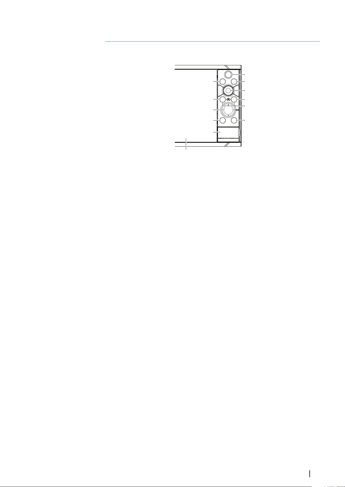
Front controls
A Touch screen
B Pages/Home
• Press to open the Home page for page selection and setup options.
C WheelKey - user configurable key. Refer to "Configurable WheelKey" on page 18.
Default without an autopilot connected to the system:
• Short press: toggles between panels on split screen.
• Long press: maximizes active panel on split screen.
Default with an autopilot connected to the system:
• Short press: opens the autopilot controller and puts the autopilot in standby
mode.
• Long press: toggles between panels on split screen.
D Menu key
• Press to display the active panel's menu.
E Rotary knob
• Turn to zoom or scroll the menu, press to select an option.
F Enter key
• Press to select an option or to save settings.
G Exit key
• Press to exit a dialog, return to previous menu level, and clear the cursor from
the panel.
H MOB
• Press simultaneously the Enter and Exit keys to create a MOB at the vessel's
position.
I Arrow keys
• Press to activate the cursor or to move the cursor.
• Menu operation: press to navigate through menu items and to adjust a value.
J Mark key
• Press to place waypoint at vessel position or at cursor position when the cursor
is active.
• Press and hold to open the Plot dialog from where you can select options to
add new or manage existing waypoints, routes and tracks
Introduction | Zeus³S Operation Manual
11
Page 12
K Power key
• Press and hold to turn the unit ON/OFF.
• Press once to display the System Controls dialog. Repeat short presses to toggle
through the default dimming levels.
L Card reader door
Card reader
A memory card can be used for:
• Chart data
• Software updates
• Transfer of user data
• Logging user data
• System backup
Note: Do not download, transfer or copy files to a chart card. Doing so can damage chart
Ú
information on the chart card.
The protective door should always be securely shut immediately after inserting or removing
a card, in order to prevent possible water ingress.
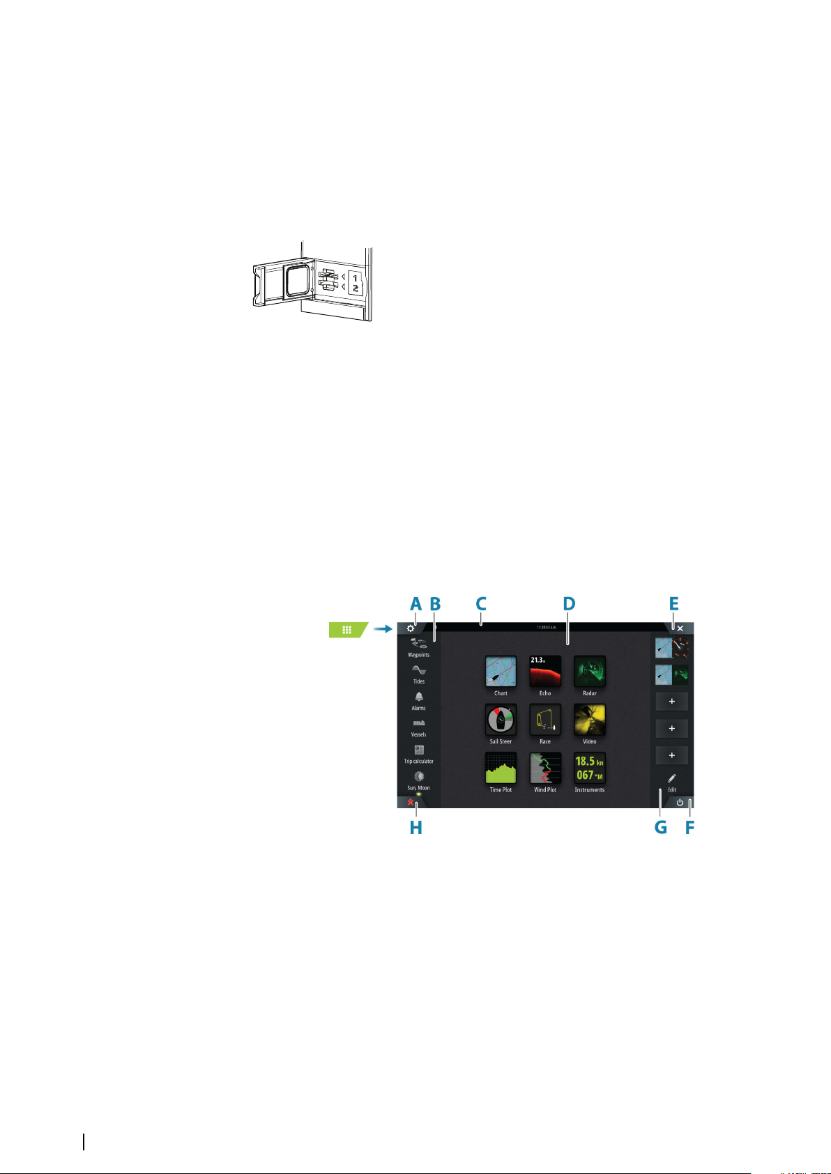
Home page
The Home page is accessed from any operation by selecting the Home button.
A Settings button
B Toolbar
C Status bar
D Application page buttons
E Close button, closes the current panel.
F System Controls button
G Favorites bar
H Man Over Board (MOB) button
12
Introduction | Zeus³S Operation Manual
Page 13

Settings button
Select to access application and feature settings dialogs. These dialogs are used to configure
the feature during installation and for making user settings. The settings dialogs are
explained toward the end of each application chapter.
Toolbar buttons
Provide access to options and tools that are not specific to any panel. For toolbar button
explanations, refer to "Tools and settings" on page 122.
Status bar
Shows the status of the system. For definitions of status bar icons, refer to "Status bar icon
definitions" on page 137.
Application buttons
Select an application button to open it. The application buttons that appear on the home
page depend on what applications are setup in your system.
Press and hold an application button to display predefined split pages for the application.
Select a predefined split page button to open the split page.
System Controls button
Opens the System Controls dialog. The System Controls dialog provides quick access to basic
system settings. Refer to "System controls dialog" on page 16.
Favorites bar
The favorites bar lists preconfigured pages and favorite pages you have made. Select a
favorite page button to open the page.
Favorite pages can be single or multiple-panel pages. The unit display size determines the
number of application panels that can be included on a favorite page.
The favorites bar also provides favorite page editing tools. All favorite pages can be modified.
For information how to add and modify favorite pages, refer to "Customizing favorite pages" on
page 19.
Favorite bar as pop-up on a page
The favorite bar can be displayed on any application page by:
• Pressing and holding the Home key
• Pressing and holding the Home button
• Pressing and holding the Pages key on a remote controller
• Simultaneously pressing the Ctrl and semicolon (;) keys on a keyboard
Man Overboard waypoint
If an emergency situation should occur, you can save a Man Overboard (MOB) waypoint at
the vessel’s current position.
Create a MOB
To create a Man Overboard (MOB) waypoint:
• Select the MOB button on the Home page
• Simultaneously press the Enter and Exit keys
• Press the MOB key on a remote controller
When you activate the MOB function, the following actions are automatically performed:
• A MOB waypoint is created at the vessel’s position
• The display switches to a zoomed chart panel, centered on the vessel's position
• The system displays navigation information back to the MOB waypoint
Introduction | Zeus³S Operation Manual
13
Page 14
Multiple MOB waypoints can be created. The vessel continues to show navigation
information to the initial MOB waypoint. Navigation to subsequent MOB waypoints needs to
be done manually.
Delete a MOB
A MOB waypoint can be deleted from the menu when the MOB is activated.
Stop navigating to MOB
The system continues to display navigational information towards the MOB waypoint until
you cancel the navigation from the menu.
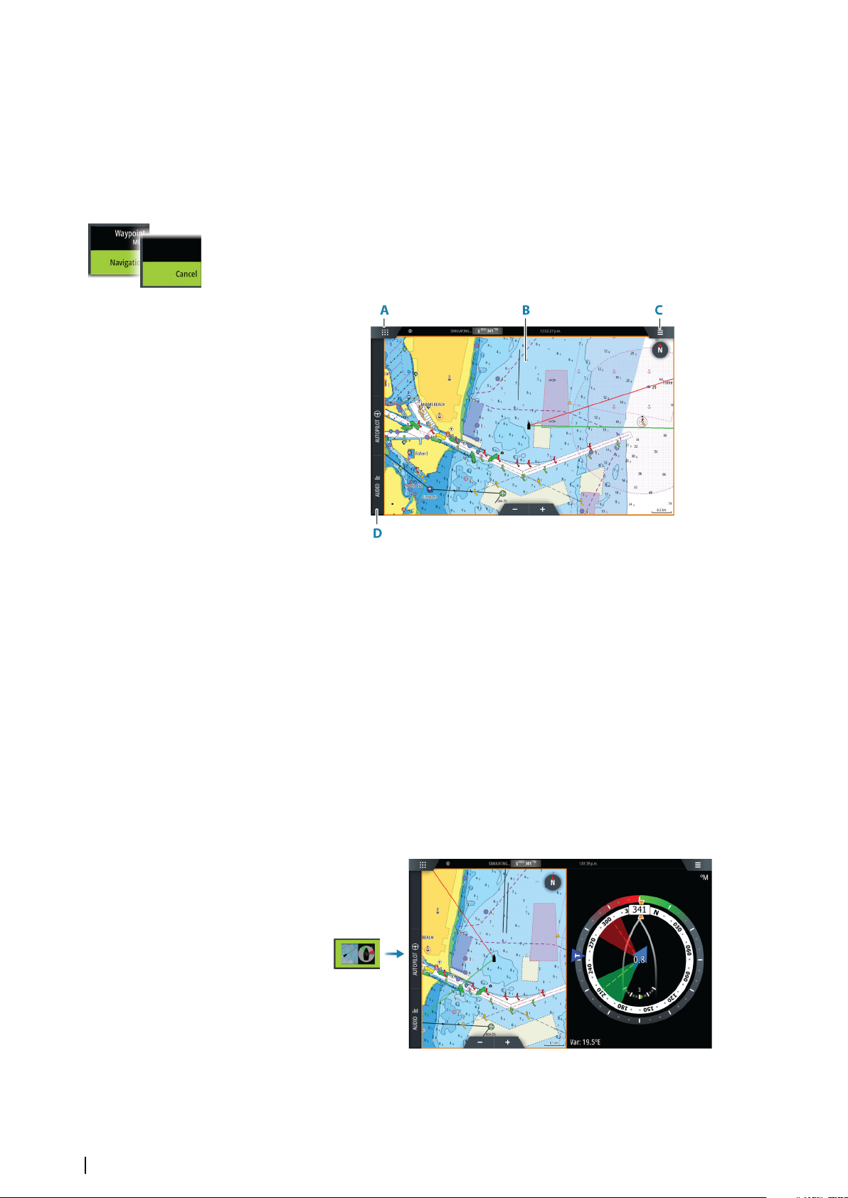
Application pages
A Home/pages button
B Application panel
C Menu button
D Control bar
Application panels
An application panel shows the application and provides a menu with customize options.
The application panels and the menu options are further explained in each application
chapter in this manual.
Predefined split pages
A predefined split page shows more than one application page on a panel.
You can adjust the split on a predefined split page. Refer to "Adjusting the split on multiple panel pages"
on page 20.
14
Menu button
Displays the menu of the active panel. Use menu options to customize the image. The panel
menu options are further explained later in this manual in each application chapter.
Introduction | Zeus³S Operation Manual
Page 15

Instrument bar
The instrument bar displays information from sensors connected to the system.
By default, the instrument bar is shown on the panel. You can turn the instrument bar off.
You can select the predefined bar to be shown and you can change the information
displayed in the predefined bar. Refer to "Customizing the instrument bar" on page 19.
Control bar
The control bar contains buttons for launching controllers or features enabled in your
system. The different controllers are described in applicable chapters later in the manual.
Introduction | Zeus³S Operation Manual
15
Page 16
Basic operation
2
Turning the system on and off
The system is turned on by pressing the Power key.
Press and hold the Power key to turn the unit off.
If the key is released before the shut-down is completed, the power off process is cancelled.
You can also turn the unit off from the System Controls dialog.
First time startup
When the unit is started for the first time, or after a reset, the unit displays a series of dialogs.
Respond to the dialog prompts to make fundamental settings.
You can perform further setup and later change settings using the system settings dialogs.
Touchscreen, keyboard and mouse operation
For touchscreen, keyboard and mouse operation details, refer to the "Appendix" on page 135.
Remote controllers
You can connect a remote controller to the network and remotely control the unit. A
separate manual is included with the remote controller.
To find out which remote controllers can be used, refer to the product web page at:
www.bandg.com
Smart devices can also be connected to the unit and remotely control the unit. For
information about how to connect smart devices to remotely control the unit, refer to "Remote
control of the MFD" on page 116.
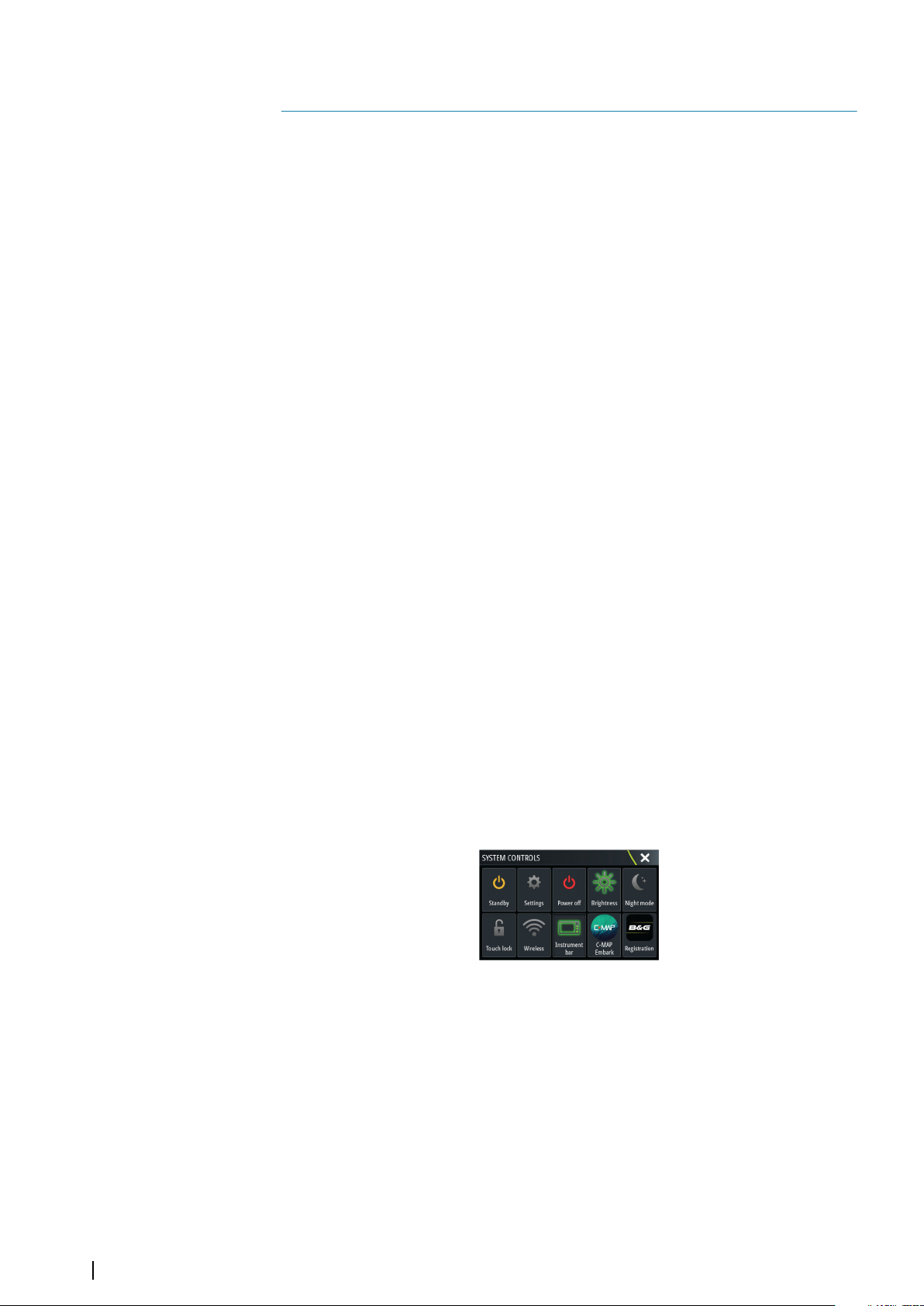
System controls dialog
The System Controls dialog provides quick access to basic system settings.
The buttons displayed on the dialog vary with operational mode and connected equipment.
For those functions that toggle on and off, a highlighted button indicates the function is
activated.
Display the dialog by:
• pressing the power key
• selecting the system controls button on the home page
• swiping down from the top of the screen on application pages
Activating functions
Select the button of the function you want to open, set or toggle on or off. For those
functions that toggle on and off, a highlighted button indicates the function is activated.
Standby mode
In Standby mode, the backlight for screen and keys are turned off to save power. The system
continues to run in the background.
You select Standby mode from the System Controls dialog.
Switch from Standby mode to normal operation by a short press on the Power key.
16
Display illumination
Basic operation | Zeus³S Operation Manual
Page 17

Brightness
You can cycle the preset backlight levels by short presses on the Power key.
The display backlighting can also be adjusted from the System Controls dialog.
Night mode
The night mode can be activated from the System Controls dialog.
The night mode option optimizes the color palette for low light conditions.
Locking the touchscreen
You can temporarily lock a touch screen to prevent accidental operation of the system.
You lock the touch screen from the system controls dialog.
When the touch lock is active, you can still operate the unit from the keys or from a remote
controller.
You remove the lock function by pressing on the power key.
Instrument bar
Toggles the Instrument bar on/off for the current page only.
Registration
Guides you how to register your device.
Screen capture
To take a screen capture:
• Simultaneously press the pages key and the power key
Screen captures are saved to internal memory.
Basic operation | Zeus³S Operation Manual
17
Page 18
Customizing your system
3
Customizing the Home page wallpaper
The Home page's wallpaper can be customized. You can select one of the pictures included
with the system, or you can use your own picture in .jpg or .png format.
The images can be available on any location that can be seen in the storage browser. When a
picture is chosen as the wallpaper, it is automatically copied to the Wallpaper folder.
Configurable WheelKey
Configures the action of the WheelKey on the front of the unit.
To configure the Wheel key, select Configure WheelKey on the System Setting dialog.
Customizing the long press feature
You can specify if the long press on the panel opens the menu or displays the cursor assist
feature on the panel.
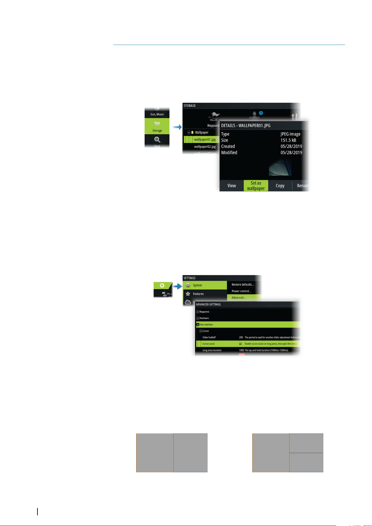
Multiple panel pages
Panel sizes in a multiple panel page can be adjusted from the System Controls dialog. Refer
to "Adjusting the split on multiple panel pages" on page 20.
In a multiple panel page, only one panel can be active at a time. The active panel is outlined
with a border.
You can only access the menu of an active panel.
18
2 panels page 3 panels page
Customizing your system | Zeus³S Operation Manual
Page 19
The shadow cursor on a multiple panel page
When using the cursor on a sonar (sonar, DownScan, or SideScan) image on a multiple panel
page, the cursor is shadowed on the other sonar (sonar, DownScan, and SideScan), chart and
radar panels.
Customizing favorite pages
Adding new favorite pages
Note: The unit display size determines the number of favorite pages allowed and the
Ú
number of application panels that can be included on a favorite page.
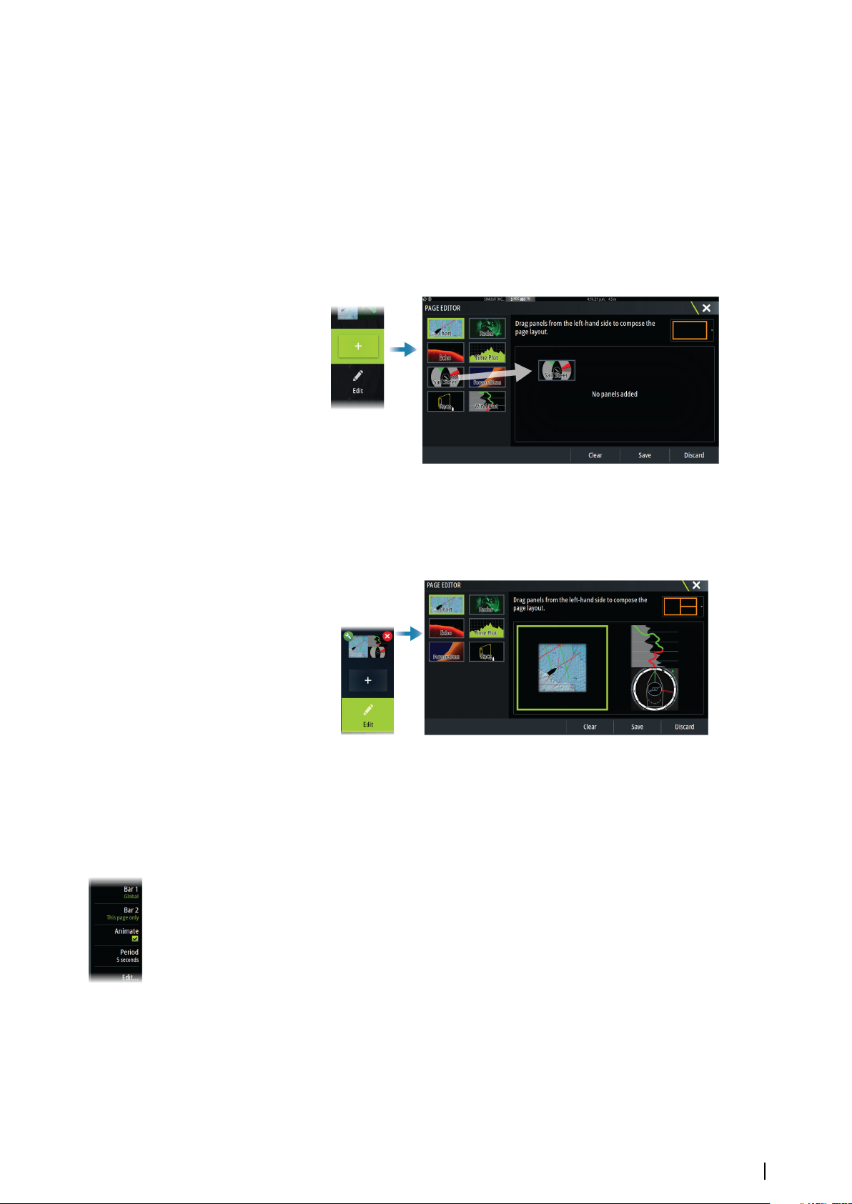
Edit favorite pages
Select the edit button in the favorite panel and then:
• Select the X icon on a favorite button to remove the page
• Select the tool icon on a favorite button to display the page editor dialog
Customizing the instrument bar
Note: You must activate the instrument bar in the application to access the instrument
Ú
bar menu.
Setting the appearance of the instrument bar
The instrument bar includes Bar 1 and Bar 2.
• Bar 1 can be global for all pages, or customized for each page
• Bar 2 is customized for each page
By default, bar 1 is shown on the panel.
You can select to display bar 1 and bar 2 at the same time.
You can turn bar 2 ON/OFF from the edit menu option.
Turning the instrument bar ON or OFF
By default, the Instrument bar is shown on the panel.
You can turn the instrument bar ON/OFF from the System Controls dialog.
Customizing your system | Zeus³S Operation Manual
19
Page 20
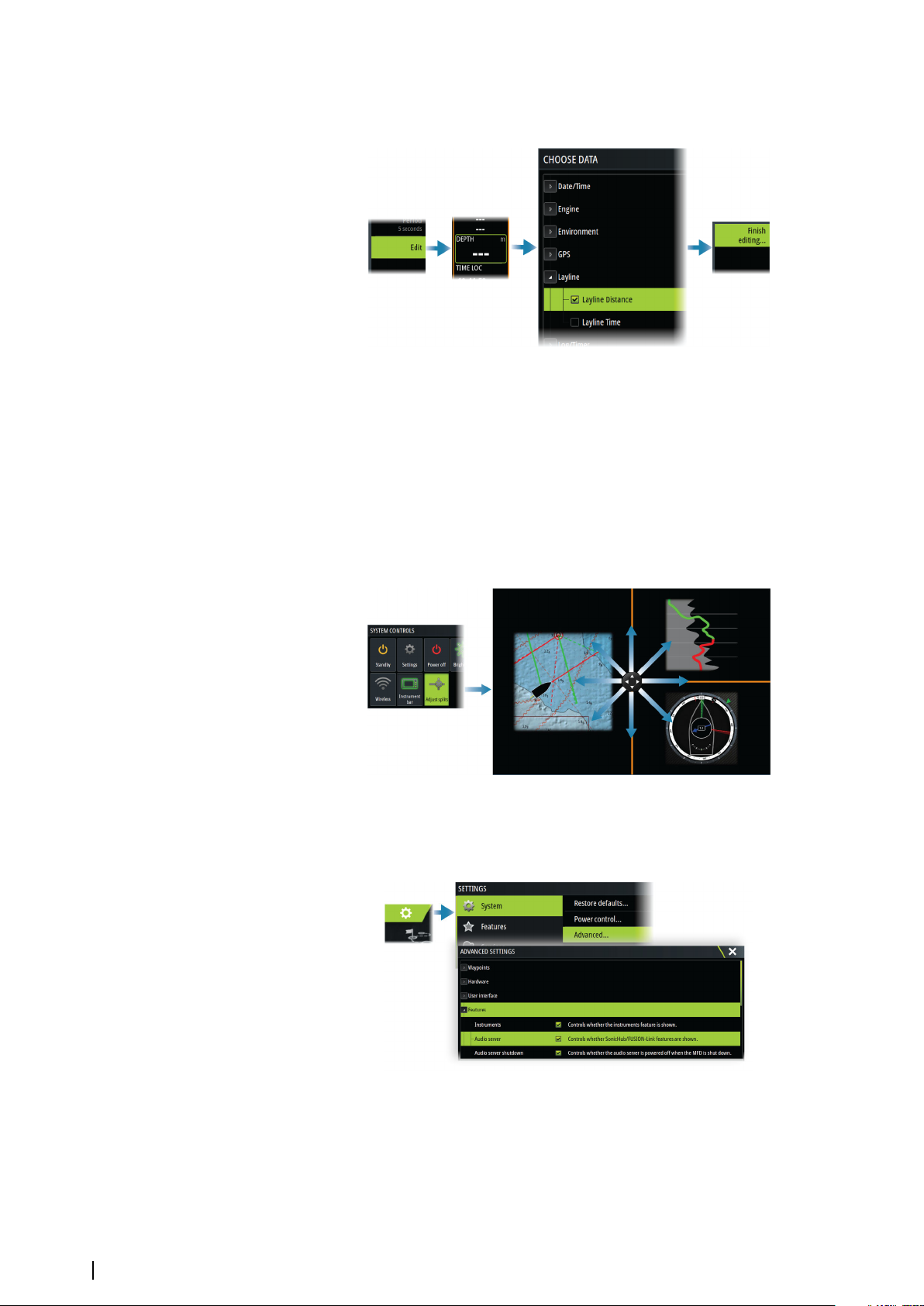
Changing data
You can change data from the menu.
Reset the instrument bar
You can reset the instrument bar from the edit menu option to show the predefined default
gauges.
Adjusting the split on multiple panel pages
1. Open the multiple panel page
2. Open the System Controls dialog
3. Select the adjust splits option. The adjustment icon appears on the multiple panel page.
4. Select the adjustment icon and move the split to the desired position
5. Use menu options to save or discard your changes.
20
Enabling or disabling features
A compatible device connected to the unit should automatically be identified by the system.
If not, enable the feature from the advanced settings dialog.
Activating/deactivating features and applications
Use the system settings features option to activate/deactivate features and applications.
Customizing your system | Zeus³S Operation Manual
Page 21
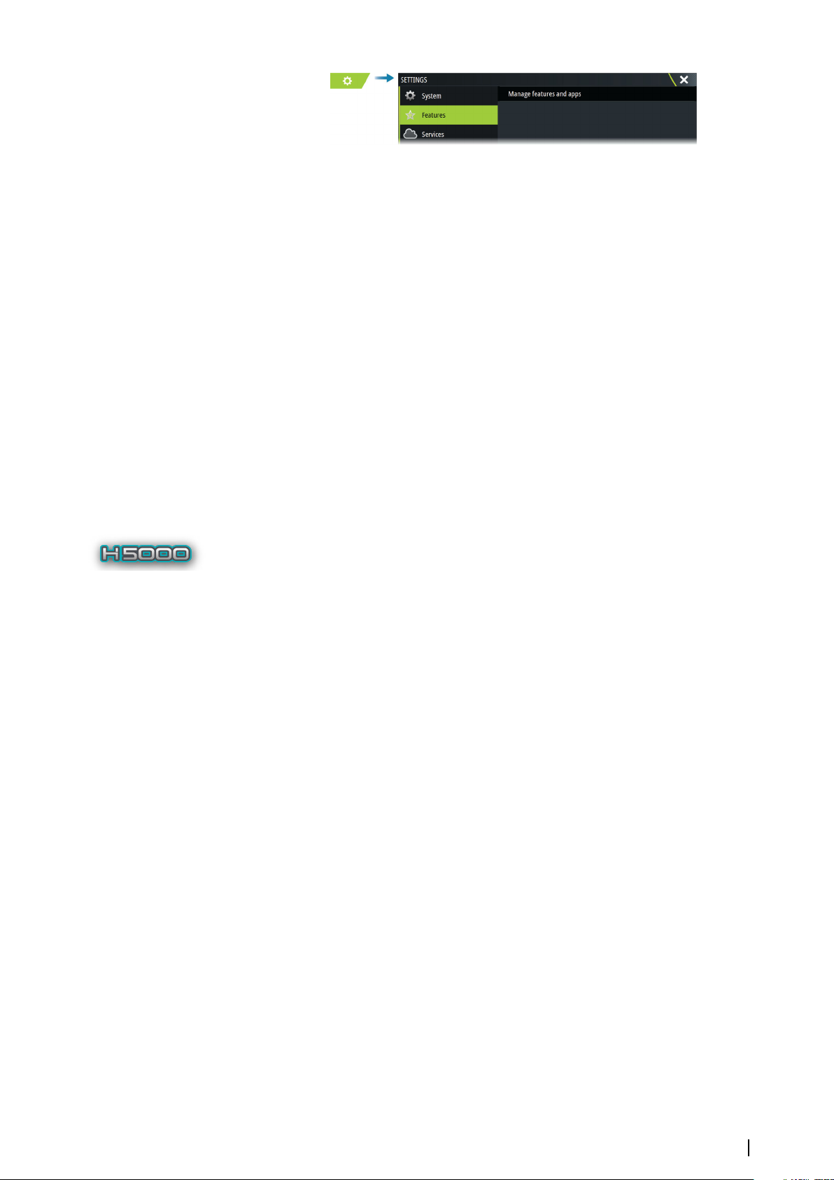
Manage features and applications
You can manage and install/uninstall the features and apps. When a feature/app is
uninstalled, the icon is removed from the home page. The feature/application can be
installed again.
Feature unlock
Some additional features can be sold separately. These features can be unlocked by entering
an unlock code.
Select the feature you want to unlock. Follow the instructions to purchase and enter the
feature unlock code.
After a feature unlock code is entered in the unit, the feature is available for use.
Note: The feature unlock option is only available if your unit supports a locked feature.
Ú
Password Protection
You can set a PIN code to prevent unauthorized access to your system's settings. Refer to "PIN
code" on page 124.
H5000 integration
The unit integrates with B&G’s H5000 Instrument and Autopilot system.
The H5000 icon will be available in the Tools panel on the Home page when an H5000
system is available on the network.
Separate documentation is provided with the H5000 system. Refer to this documentation for
how to install and configure the H5000 system.
Customizing your system | Zeus³S Operation Manual
21
Page 22
Charts
4
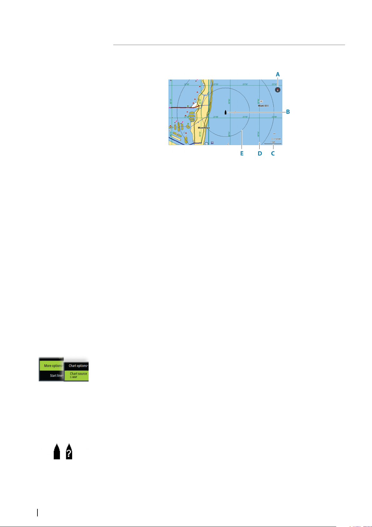
The Chart panel
A North indicator
B Vessel
C Chart range scale
D Grid lines*
E Range rings*
* Optional chart items. Optional chart items can be turned on/off individually from the chart
settings dialog.
Chart data
The system can be delivered with preloaded cartography.
For a full selection of supported charts, visit the product web site.
Note: Chart menu options vary depending on the chart you are using.
Ú
Charts on chart cards are shared over the Ethernet network, so only one chart card per vessel
is required.
Note: The system does not automatically switch to preloaded cartography if the chart
Ú
card is removed. A low-resolution chart will be displayed until you re-insert the card or
manually switch back to the preloaded cartography.
Selecting chart source
Available chart sources are listed in the menu.
If you have identical chart sources available, the system automatically selects the chart with
most chart details for your displayed region.
Showing dual chart sources
If you have different chart sources available, you can show two different chart sources
simultaneously on a page that has two chart panels.
Activate each chart page and select its source in the menu.
22
Vessel symbol
When the system has a valid GPS position lock, the vessel symbol indicates vessel position. If
no GPS position is available, the vessel symbol includes a question mark.
If heading information is not available, the vessel icon orientates itself using COG (Course
over Ground).
Charts | Zeus³S Operation Manual
Page 23
Zooming the chart
The chart range scale and range rings interval (when turned on) are shown on the chart
panel. You change the scale by zooming the chart in or out.
Panning the chart
You can move the chart in any direction by:
• Dragging the screen
• Move the cursor to the edge of the chart panel using the arrow keys
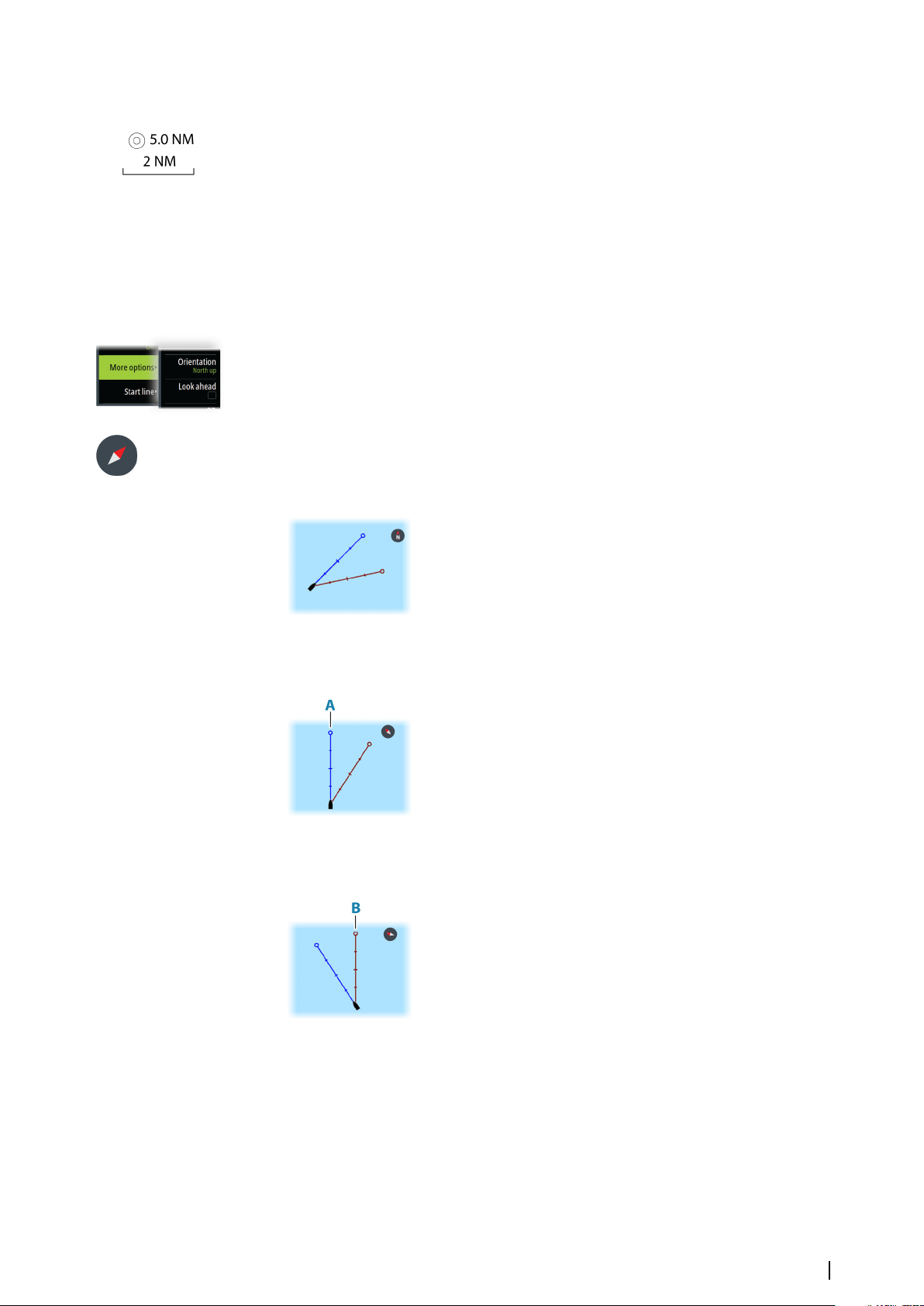
Chart orientation
You can specify how the chart is rotated in the panel.
Chart orientation button
In addition to using the menu to specify the chart orientation, you can also select the chart
orientation button on the panel to toggle between different orientations.
The red arrow in the chart orientation button indicates the north direction.
North up
Heading up
Course up
Displays the chart with north upward.
Displays the chart with the vessel’s heading (A) directed
upward. Heading information is received from a compass. If
heading is not available, then the COG from the GPS is used.
The chart direction is depending on if navigating or not:
• When navigating: the desired course line (B) is oriented up
• When not navigating: the direction the vessel is actually
traveling (COG) is oriented up
Look ahead
Moves the vessel icon on the panel to maximize your view ahead of the vessel.
Displaying information about chart items
When you select a chart item, a waypoint, a route, or a target, basic information for the
selected item is displayed. Select the chart item's pop-up to display all available information
for that item. You can also activate the detailed information dialog from the menu.
Charts | Zeus³S Operation Manual
23
Page 24
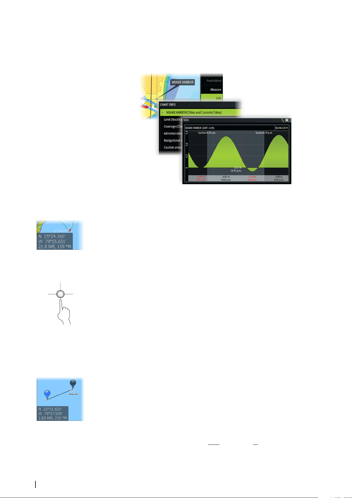
Note: If you are viewing applicable C-MAP charts on your system, you can select marine
Ú
objects to display information about services and available multimedia (photos)
associated with the location or object.
Note: Pop-up information has to be enabled in chart settings to see basic item
Ú
information.
Using the cursor on the panel
By default, the cursor is not shown on the panel.
When you activate the cursor, the cursor position window is displayed. When the cursor is
active, the panel does not pan or rotate to follow the vessel.
Go to cursor
You can navigate to a selected position on the image by positioning the cursor on the panel,
and then using the go to cursor menu option.
The cursor assist function
Note: The cursor assist function is available if it is enabled. Refer to "Customizing the long press
Ú
feature" on page 18.
The cursor assist function allows for fine tuning and precision placement of the cursor
without covering details with your finger.
Activate the cursor on the panel, then press and hold your finger on the screen to switch the
cursor symbol to a selection circle, appearing above your finger.
Without removing your finger from the screen, drag the selection circle to the desired
position.
When you remove your finger from the screen the cursor reverts to normal cursor operation.
Measuring distance
The cursor can be used to measure the distance between your vessel and a selected position,
or between 2 points on the chart panel.
1. Position the cursor on the point where you want to measure the distance to. Start the
measure function from the menu
-
The measuring icons appear with a line drawn from the vessel center to the cursor
position, and the distance is listed in the cursor information window.
2. The measuring points can be repositioned by dragging either icon while the measuring
function is active.
24
Note: The bearing is always measured
Ú
The start measuring function can also be started without an active cursor. Both measuring
icons are then initially located at the vessel position. The grey icon follows the vessel as the
Charts | Zeus³S Operation Manual
from the grey icon to the blue icon.
Page 25
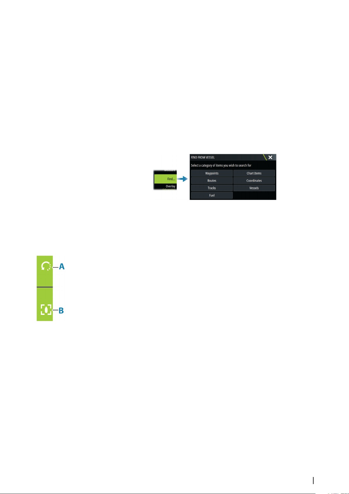
vessel moves, while the blue icon remains at the position given when you activated the
function. The measuring points can then be repositioned by dragging either icon.
Terminate the measuring function by selecting the finish measuring option.
Creating routes on the chart panel
1. Activate the cursor on the chart panel
2. Select the new route option from the menu
3. Position the first waypoint on the chart panel
4. Continue positioning the remaining routepoints
5. Save the route by selecting the save option in the menu.
Find objects on chart panels
You can search for other vessels or various chart items from a chart panel.
Activate the cursor on the panel to search from the cursor position. If the cursor is not active,
the system searches for items from the vessel's position.
Note: You must have a SiriusXM Marine subscription to search for fueling stations.
Ú
Note: You must have an AIS receiver connected to search for vessels.
Ú
3D charts
The 3D option provides a three dimensional graphical view of land and sea contours.
Note: All chart types work in 3D mode, but without 3D cartography for the appropriate
Ú
area the chart appears flat.
When the 3D chart option is selected, the rotate (A) and the pan (B) icons appear on the
chart panel.
Panning the 3D chart
You can move the chart in any direction by selecting the Pan icon and then panning in the
desired direction.
To return the chart to vessel position use the return to vessel option.
Controlling the view angle
You can control the view angle by selecting the rotate icon, and then panning the chart
panel.
• To change the direction you are viewing, pan horizontally
• To change the tilt angle of the view, pan vertically
Note: When centered on the vessel position, only the tilt angle can be adjusted. The
Ú
view direction is controlled by the chart orientation setting. Refer to "Chart orientation" on
page 23.
Tracks
Opens the Tracks dialog. Use this dialog to manage tracks, refer to "Tracks" on page 41.
Color tracks based on data
A track can be colored based on what source data and the high/low limits you set:
Charts | Zeus³S Operation Manual
25
Page 26
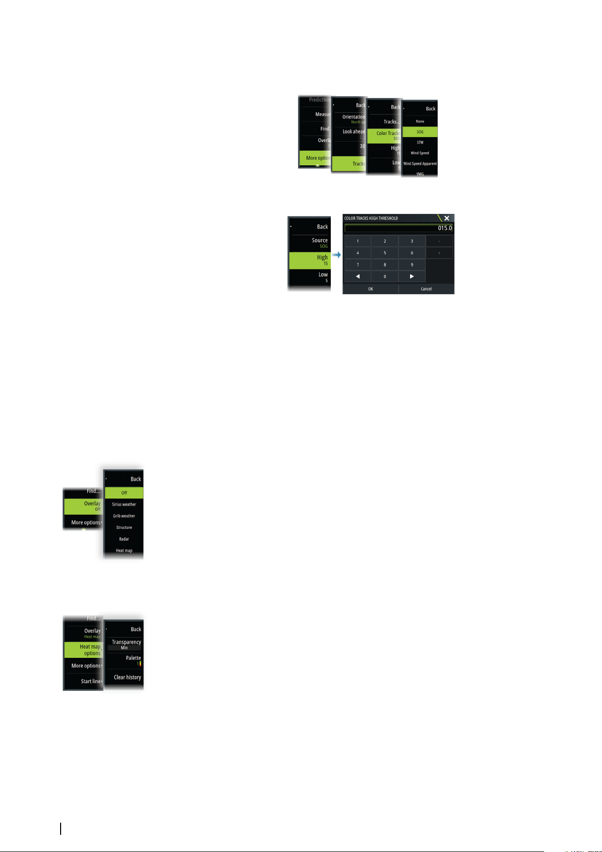
• You can specify the source (data type) to be colored. To turn off coloring, select source
None.
• Select the high and low options to set high and low values.
The colors can be shades of green, yellow, and red. Green is for the high limit you set. Yellow
is the value that is the average of the high and low. Red is for the low limit. If the value is
between the high and the middle values, it appears as a greenish-yellow color. If the value is
between the middle and the low, it appears as an orange color.
Note: By default, tracks are colored according to the color setting in the Edit Track dialog.
Ú
Coloring tracks based on source data overrides the coloring specified in the Edit Track
dialog.
If two or more charts are displayed in a split panel, changing the color source or high/low
values on one chart does not change the other charts.
Chart overlay
You can add overlays on the chart panel.
When an overlay is selected, the chart menu expands to include basic menu options for the
selected overlay.
Information about the overlay menu options are described in more detail below or in their
separate sections in this manual.
Heat map overlay
The Heat map overlay feature shows a history of water temperature coloring on the chart. A
water temperature source is needed to provide the temperature data for the overlay.
The color range is adjusted automatically based on the minimum and maximum
temperatures recorded.
Transparency
Adjusts the transparency of the overlay. With a minimum transparency setting, the panel
details are almost hidden by the overlay.
26
Palette
Specifies the colors used to show water temperatures. A legend is shown on the panel that
identifies the colors associated with the recorded temperatures.
Clear history
Deletes all heat map data gathered up to the moment it is selected. Heat map data is
automatically deleted when the unit is turned off.
Charts | Zeus³S Operation Manual
Page 27
PredictWind weather and routing
For information about PredictWind weather and PredictWind routing, refer to "PredictWind" on
page 59.
C-MAP charts
All possible menu options for C-MAP charts are described below. The features and menu
options available can vary depending on the charts you use. This section shows menus from
a C-MAP chart.
Note: A menu option is greyed out if the feature is not available on the chart displayed.
Ú
C-MAP tides and currents
The system can display C-MAP tides and currents. With this information it is possible to
predict the time, level, direction and strength of currents and tides. This is an important tool
when considering planning and navigation of a trip.
In large zoom ranges the tides and currents are displayed as a square icon including the
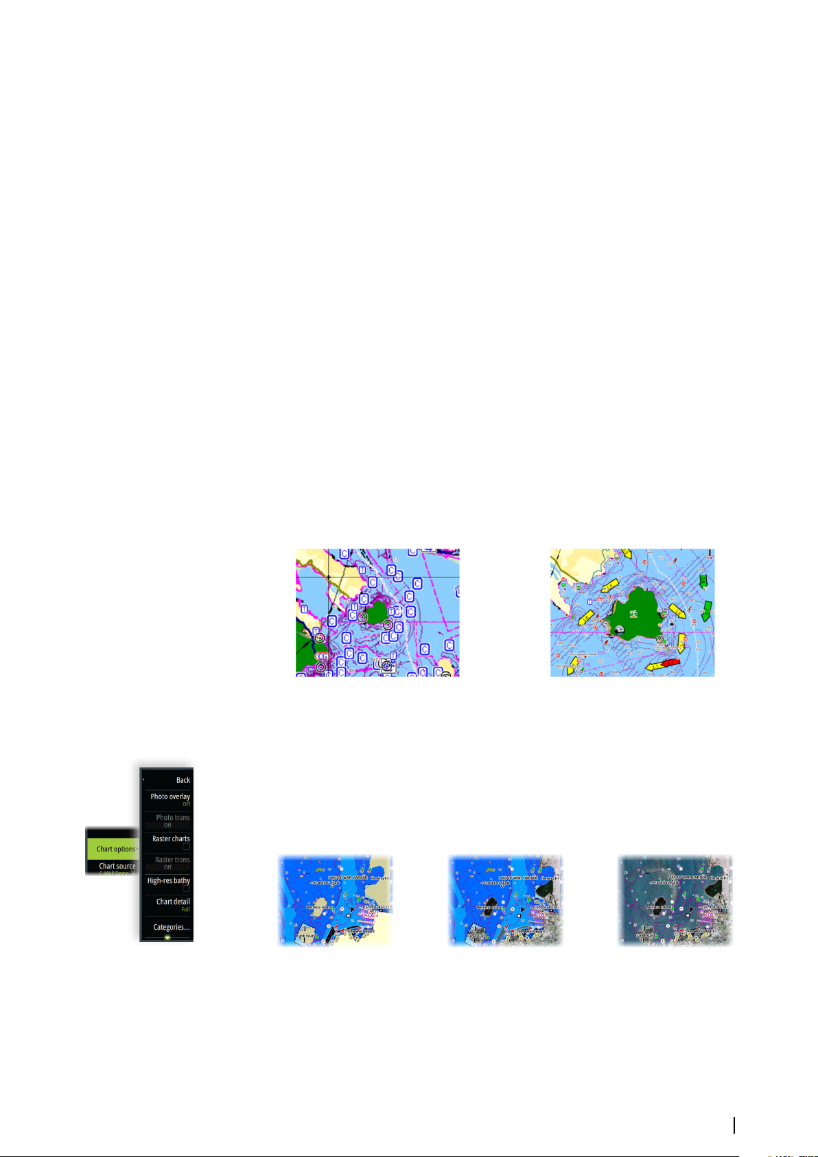
letter T (Tides) or C (Current). When you select one of the icons, tidal or current information
for that location are displayed.
Dynamic current data can be viewed by zooming inside a 1-nautical mile zoom range. At
that range, the Current icon changes to an animated dynamic icon that shows the speed and
direction of the current. Dynamic icons are colored in black (greater than 6 knots), red
(greater than 2 knots and less than or equal to 6 knots), yellow (greater than 1 knot and less
than or equal to 2 knots) or green (equal to or less than 1 knot), depending on the current in
that location.
If there is no current (0 knots) this will be shown as a white, square icon.
Static Current and Tide icons Dynamic Current icons
C-MAP specific chart options
Photo overlay
Photo overlay enables you to view satellite photo images of an area as an overlay on the
chart. The availability of such photos is limited to certain regions, and cartography versions.
You can view photo overlays in either 2D or 3D modes.
No Photo overlay Photo overlay, land only Full Photo overlay
Photo transparency
The Photo transparency sets the opaqueness of the photo overlay. With minimum
transparency settings the chart details are almost hidden by the photo.
Charts | Zeus³S Operation Manual
27
Page 28
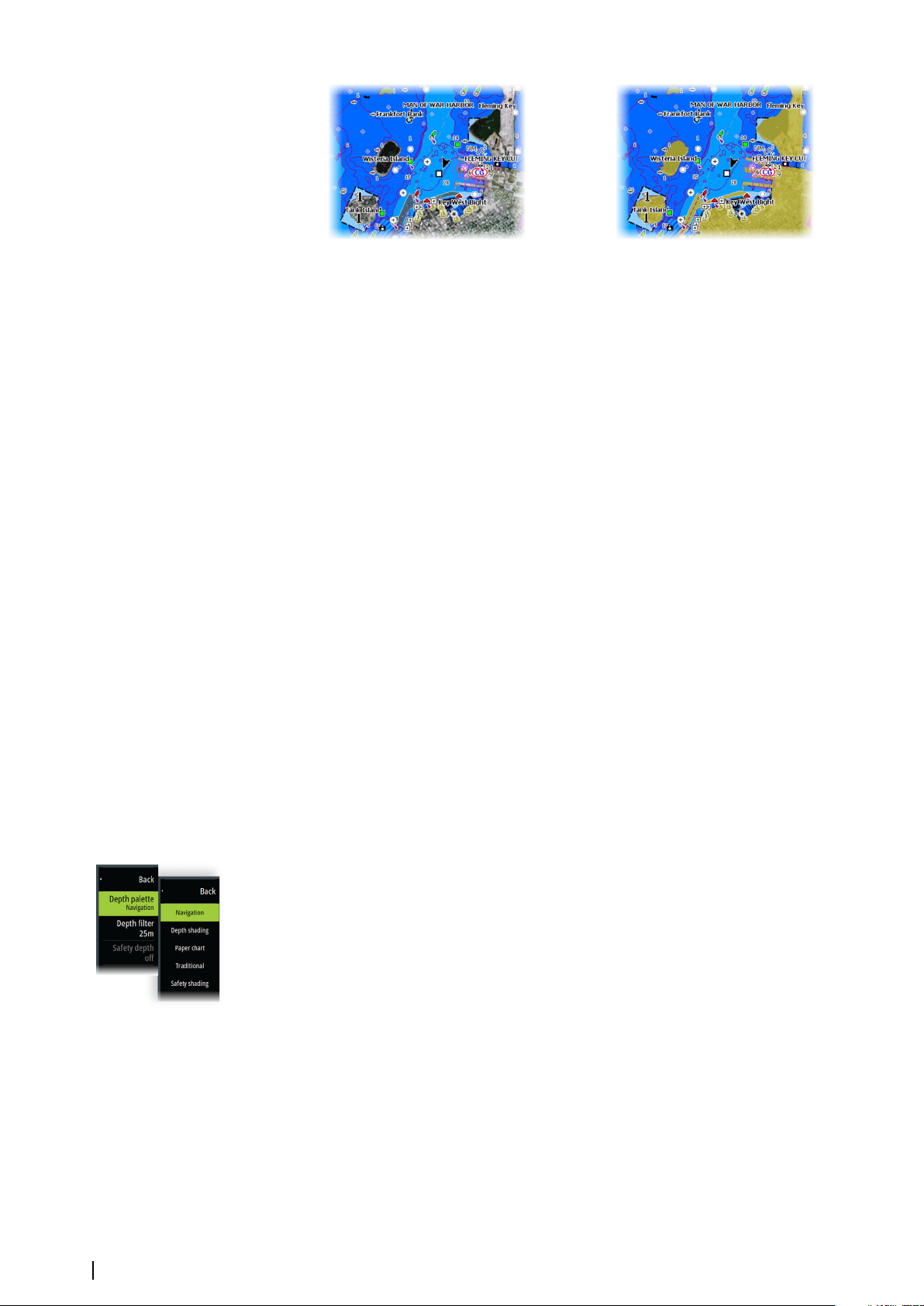
Minimum transparency Transparency at 80
Raster charts
Changes the view to that of a traditional paper chart.
Raster transparency
Controls the transparency of raster imagery.
High resolution bathymetry
Enables and disables higher concentration of contour lines.
Chart detail
• Full - displays all available information for the chart in use.
• Medium - displays minimum information sufficient for navigation.
• Low - displays basic level of information that cannot be removed, and includes
information that is required in all geographic areas. It is not intended to be sufficient for
safe navigation.
Chart categories
Several categories and sub-categories are included. You can turn on/off individually
depending on which information you want to see.
The categories listed in the dialog are dependent on the charts used.
Shaded relief
Shades seabed terrain.
No contours
Removes contour lines from the chart.
Depth palette
Controls the Depth palette used on the map.
Navigation
Color shades depth areas based on depth range values set by the system. If the depth is
within a certain range the system will select the exact color of that range. It colors darker
shades of blue in shallower water and whiter in deeper water.
Depth shading
Color shades depth areas based on the depth value of the depth range shade. The system
will interpolate a color based on the depth within the range. It colors darker shades of blue in
deeper water and whiter in shallower water.
Paper chart
Color shades the depths similar to the National Oceanic and Atmospheric Administration
(NOAA) colors present in the paper charts.
28
Traditional
Color shades depth areas based on the data defined by the chart data. Charts have their own
color palette that is defined in the chart data.
Charts | Zeus³S Operation Manual
Page 29
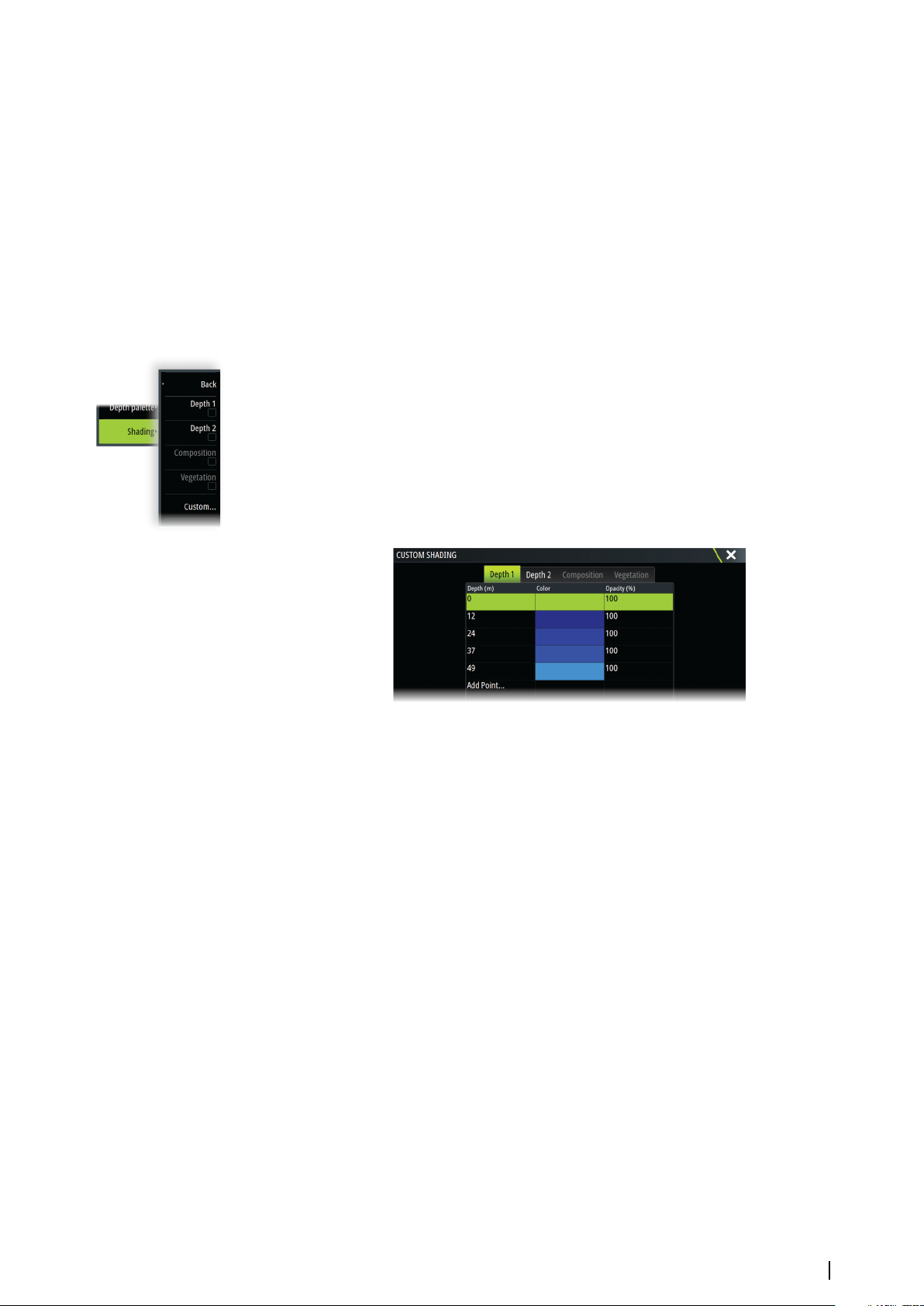
Safety shading
Color shades depth areas based on the safety depth limit. The limit determines which depths
will be drawn without blue shading.
Depth filter
Filters out depth values shallower than the selected depth filter limit.
Safety depth
Charts use different shades of colors to distinguish between shallow and deep water. After
enabling the safety shading depth palette, specify the desired safety depth limit and the
color/shading for different depths.
Shading
Shades different areas of the seabed, depending on the selected Shading category.
Note: Composition and Vegetation shading are not applicable to C-MAP charts.
Ú
Depth 1 and Depth 2
Depth presets that shade different depths in different colors.
Custom
You can adjust the depth threshold, color and opacity (transparency) of color shading for
Depth 1 and Depth 2.
3D exaggeration
Graphical settings that are available in 3D mode only. Exaggeration is a multiplier applied to
the drawn height of hills on land, and troughs in water to make them look taller or deeper.
Note: This option is grayed out if the data is not available in the map card inserted.
Ú
Genesis Layer
The Genesis Layer displays high-resolution contours contributed by Genesis users that have
passed a quality check.
This option toggles the Genesis layer on/off on the chart image.
Available only if the C-MAP chart contains Genesis Layer data.
Navionics charts
Some Navionics features require the most current data from Navionics. For those features, a
message is displayed stating that the feature is unavailable if you do not have the
appropriate Navionics charts or chart card inserted. For more information on what is required
for these features, refer to www.navionics.com.
You can also get a message if you try to use a restricted feature when the Navionics chart
card is not activated. To activate the card, contact Navionics.
Charts | Zeus³S Operation Manual
29
Page 30
Navionics specific chart options
Photo overlay
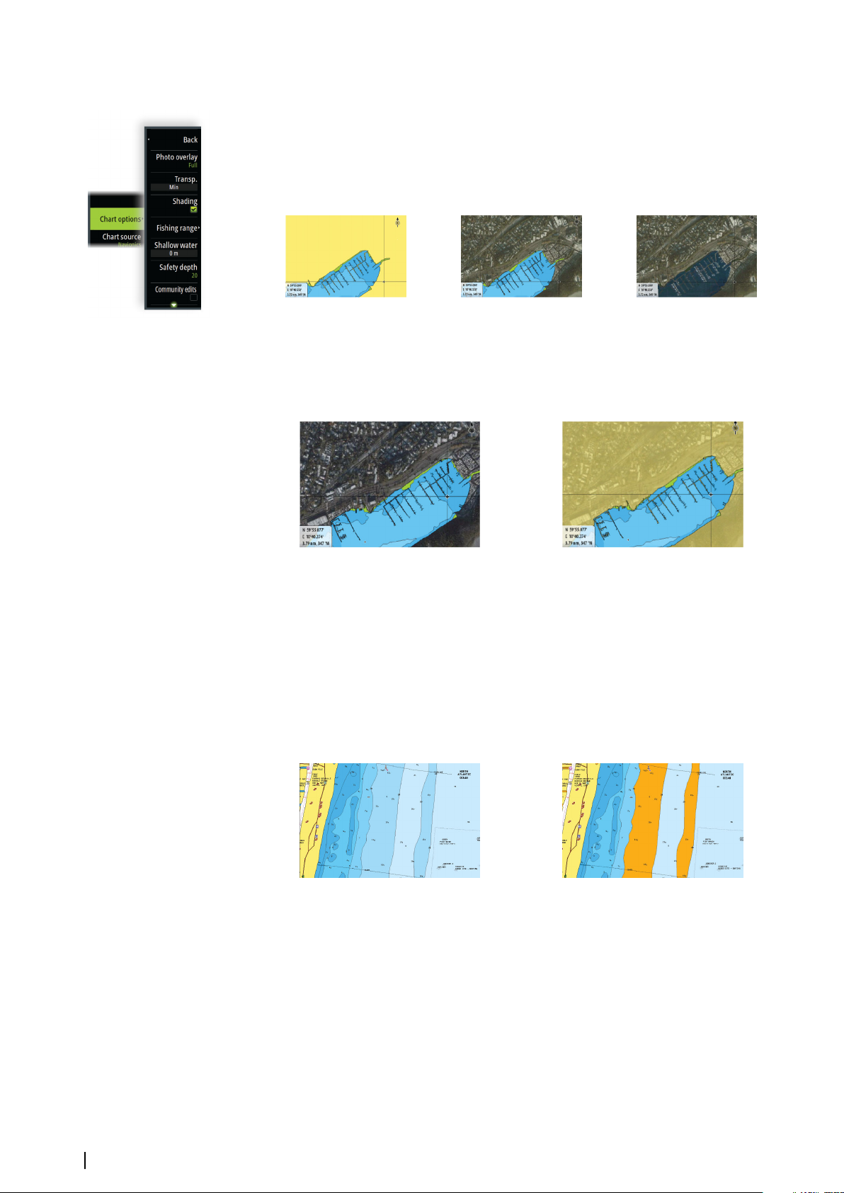
Photo overlay enables you to view satellite photo images of an area as an overlay on the
chart. The availability of such photos is limited to certain regions, and cartography versions.
You can view photo overlays in either 2D or 3D modes.
No Photo overlay Photo overlay, land only Full Photo overlay
Photo transparency
The Photo transparency sets the opaqueness of the photo overlay. With minimum
transparency settings the chart details are almost hidden by the photo.
Minimum transparency Maximum transparency
Chart shading
Shading adds terrain information to the chart.
Fishing range
Select a range of depths between which Navionics fills with a different color.
This allows you to highlight a specific range of depths for fishing purposes. The range is only
as accurate as the underlying chart data, meaning that if the chart only contains 5 meter
intervals for contour lines, the shading is rounded to the nearest available contour line.
No Depth highlight range Depth highlight range: 6 m - 12 m
Shallow water highlight
This highlights areas of shallow water between 0 and the selected depth (up to 10 meters/30
feet).
30
Charts | Zeus³S Operation Manual
Page 31
No shallow water highlighted Shallow water highlight: 0 m - 3 m
Safety depth
The Navionics charts use different shades of blue to distinguish between shallow and deep
water.
Safety depth, based on a selected limit, is drawn without blue shading.
Note: The built in Navionics database features data down to 20 m, after which it is all
Ú
white.
Community edits
Toggles on the chart layer including Navionics edits. These are user information or edits
uploaded to Navionics Community by users, and made available in Navionics charts.
For more information, refer to Navionics information included with your chart, or to
Navionics website: www.navionics.com.
SonarChart
The system supports the Navionics SonarChart feature.
SonarChart displays a bathymetry map showing high resolution contour detail and standard
navigational data. For more information, refer to www.navionics.com.
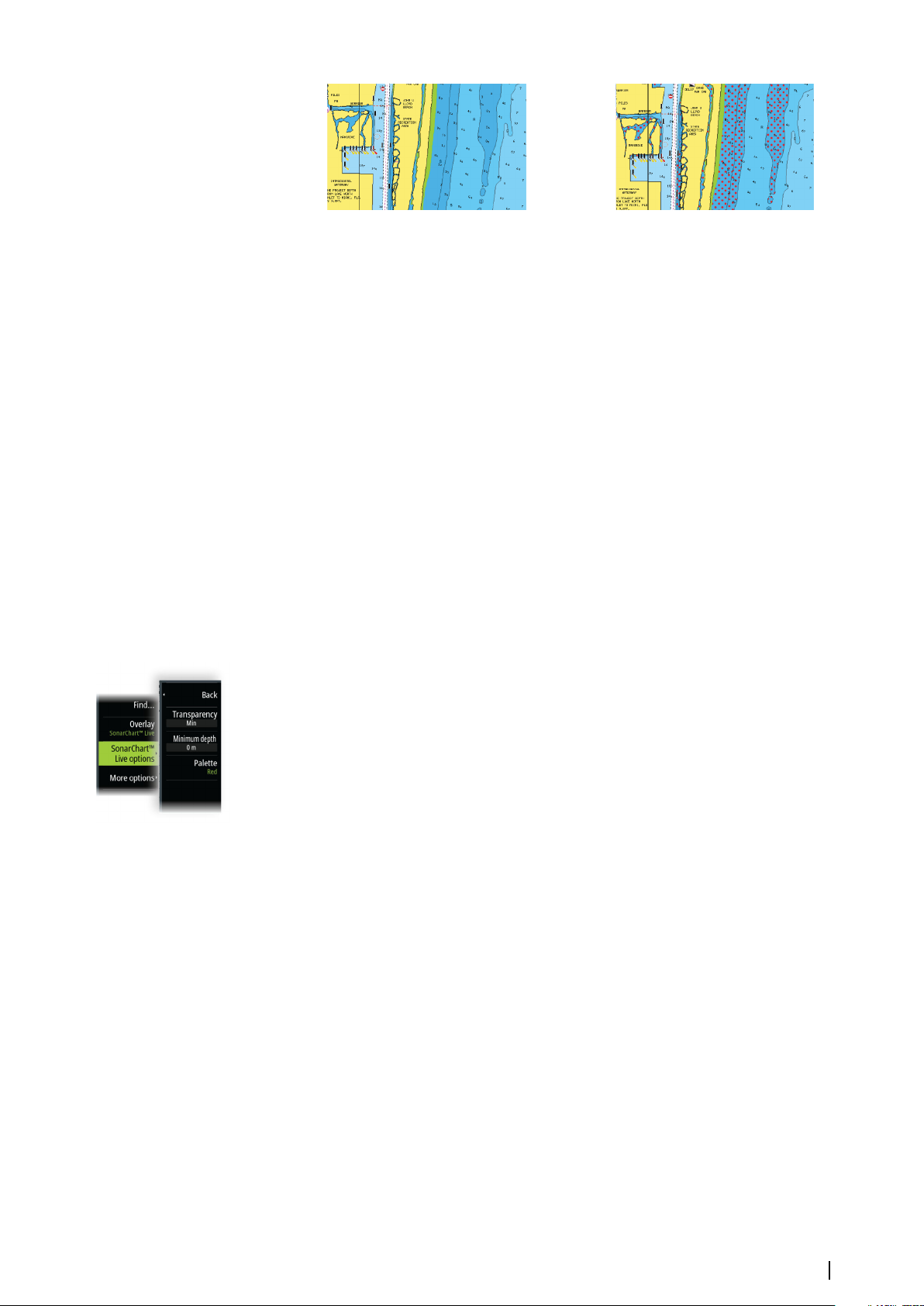
SonarChart Live
SonarChart Live is a real-time feature where the device creates an overlay of depth contours
based on your own live sonar soundings.
When you select SonarChart Live overlay the menu expands to display SonarChart Live
options.
Transparency
The SonarChart Live overlay is drawn on top of other chart data. The chart data is completely
covered at minimum transparency. Adjust the transparency to allow the chart details to be
seen.
Minimum depth
Adjusts what SonarChart Live rendering treats as the safety depth. This affects the coloring of
the SonarChart Live area. As the vessel approaches the safety depth, the SonarChart Live area
will gradually change from a simple grey/white to red.
Palettes
Used for selecting the image's color palette.
SCL History
Select to display previously recorded data on the chart overlay.
SC Density
Controls the density of the SonarChart and SonarChart Live contours.
Colored seabed areas
Used for displaying different depth areas in different shades of blue.
Charts | Zeus³S Operation Manual
31
Page 32
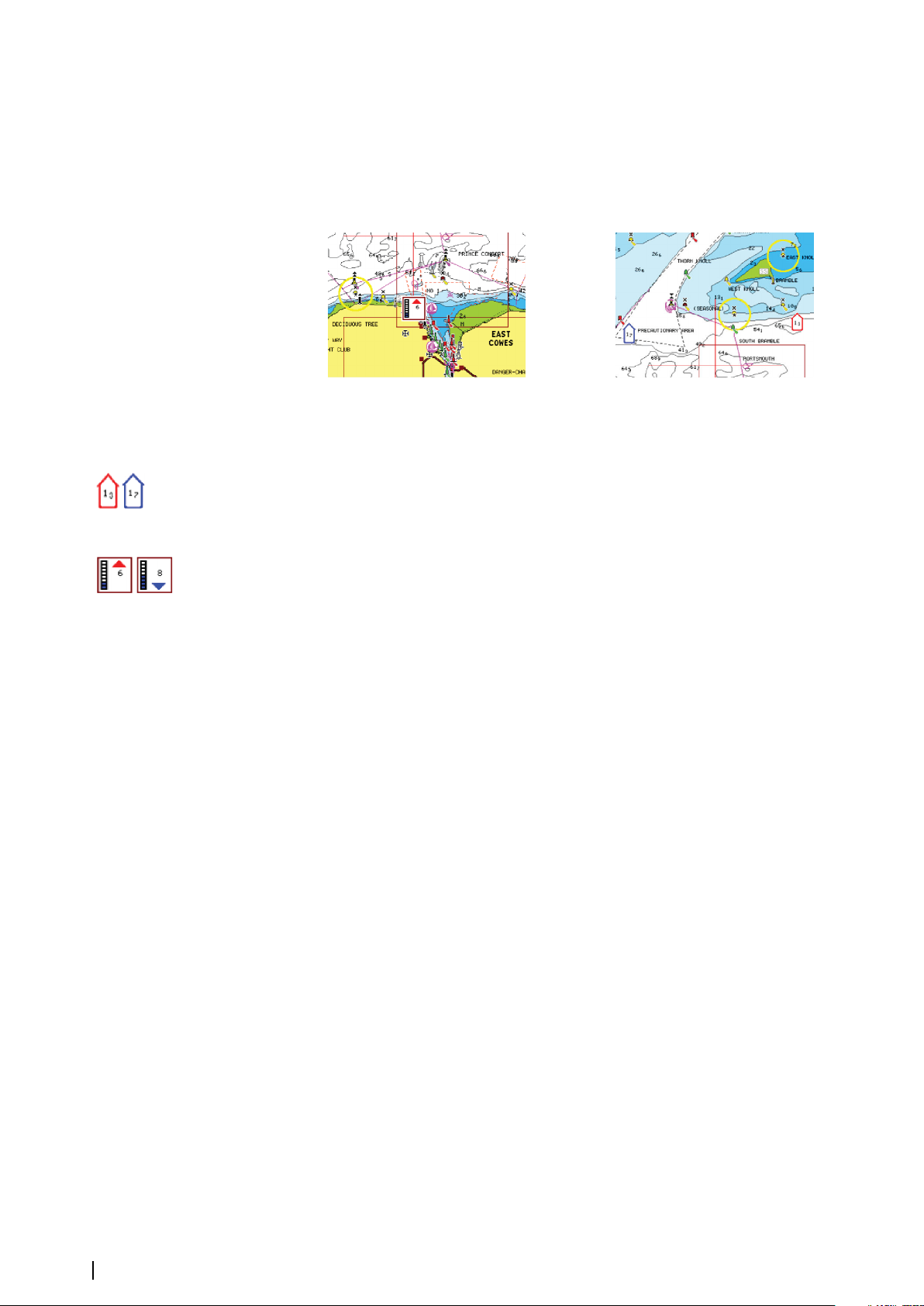
Navionics Dynamic tides and current icons
Shows tides and currents with a gauge and an arrow instead of the diamond icons used for
static tides and current information.
The tide and current data available in Navionics charts are related to a specific date and time.
The system animates the arrows and/or gauges to show the tides and currents evolution
over time.
Dynamic tide information Dynamic current information
The following icons and symbology are used:
Current speed
The arrow length depends on the rate, and the symbol is rotated according to flow direction.
Flow rate is shown inside the arrow symbol. The red symbol is used when current speed is
increasing, and the blue symbol is used when current speed is decreasing.
Tide height
The gauge has 8 labels and is set according to absolute max/min value of the evaluated day.
The red arrow is used when tide is rising, and the blue arrow is used when tide is falling.
Note: All numeric values are shown in the relevant system units (unit of measurement)
Ú
set by user.
Rock filter level
Hides rock identification on the chart beneath a given depth.
This helps you to declutter charts in areas where there are many rocks located at depths well
below your vessel's draught.
Contours depth
Determines which contours you see on the chart down to the selected safety depth value.
Presentation type
Displays marine charting information such as symbols, colors of the navigation chart and
wording for either International or U.S. presentation types.
Annotation
Determines what area information, such as names of locations and notes of areas, is available
to display.
Chart details
Provides you with different levels of geographical layer information.
Easy View
Magnifying feature that increases the size of chart items and text.
32
Note: There is no indication on the chart showing that this feature is active.
Ú
Chart settings
The options in the chart settings dialog depends on which chart source is selected in the
system.
Charts | Zeus³S Operation Manual
Page 33
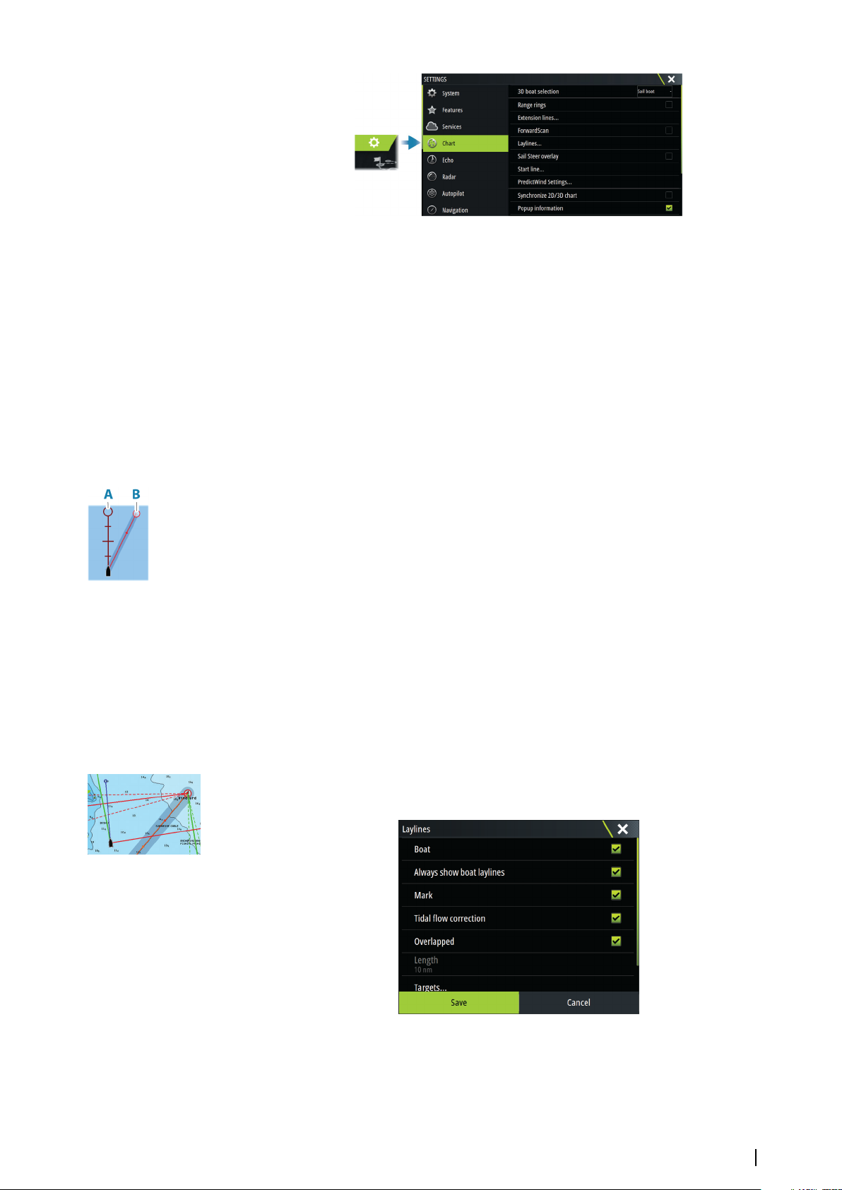
3D boat selection
Determines which icon to use on 3D charts.
Range rings
The range rings can be used to present the distance from your vessel to other panel objects.
The range scale is set automatically by the system to suit the panel scale.
Extension lines
Sets the lengths of the extension lines for your vessel and for other vessels shown as AIS
targets.
Select to show or hide the heading and course extension lines for your vessel.
Extension length
A: Heading
B: Course Over Ground (COG)
The length of the extension line is either set as a fixed distance, or to indicate the distance
the vessel moves in the selected time period. If no options are turned on for the vessel then
no extension lines are shown.
Your vessel heading is based on information from the active heading sensor and the COG is
based on information from the active GPS sensor.
Your vessel heading and the COG is based on information from the GPS.
For other vessels, COG data is included in the message received from the AIS system.
ForwardScan
If you have ForwardScan and this option is selected, the ForwardScan heading extension is
shown on the chart. Refer to "Heading extension" on page 101.
Laylines
Configures the options for laylines on the chart and on the SailSteer panels.
The image shows laylines from mark/waypoint with limits.
Boat
Displays laylines from boat, indicating the target course.
Charts | Zeus³S Operation Manual
33
Page 34
Always show boat laylines
Displays boat laylines.
Mark
Displays laylines from mark/waypoint, indicating the target course to sail to reach the mark/
waypoint.
Tidal flow correction
Applies the system calculated tidal vector to the laylines to adjust for tidal flow.
Overlapped
Extends the laylines beyond the tack/gybe intersection.
Length
Sets the length of the laylines.
Note: This option is only available if Boat is not selected.
Ú
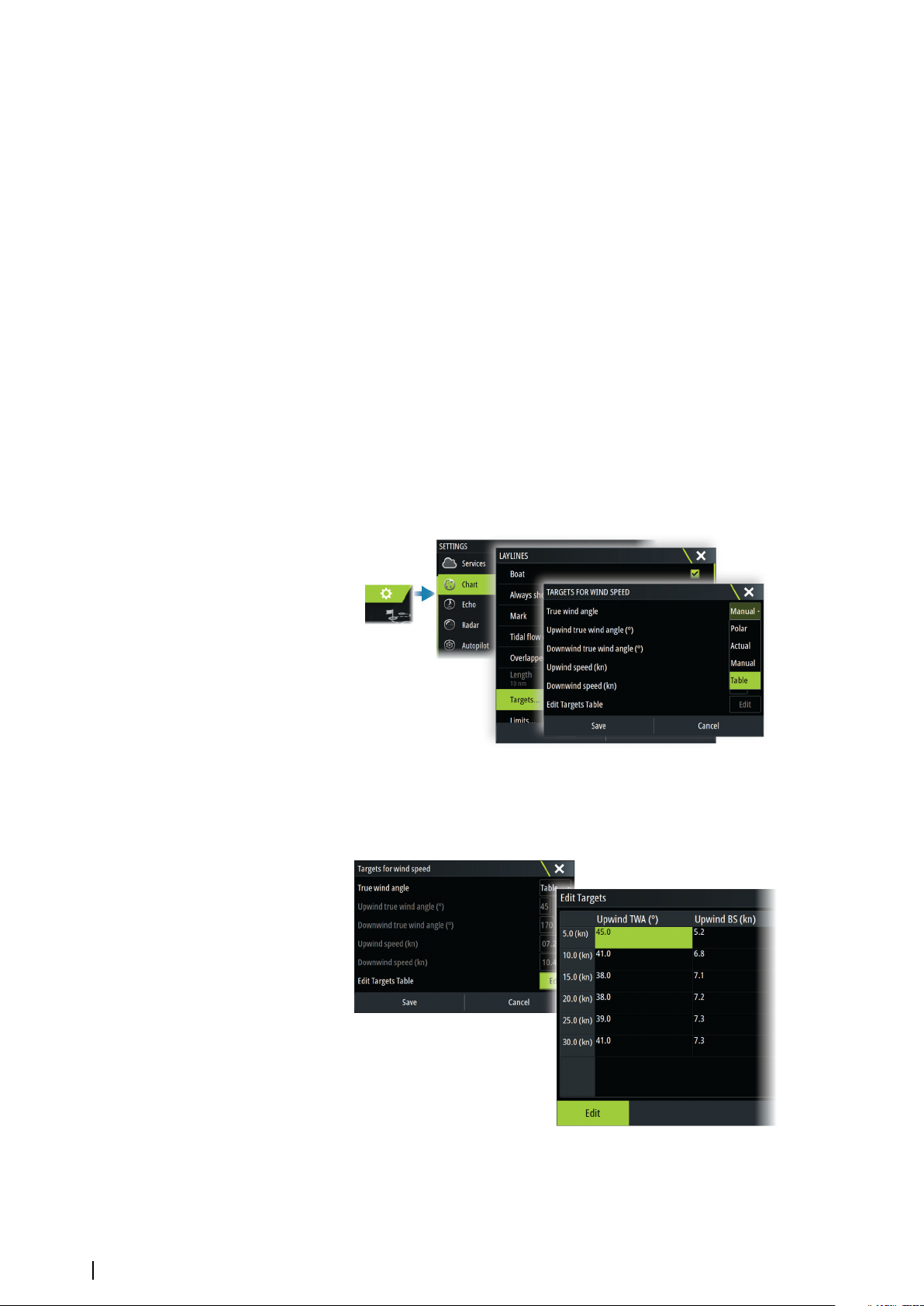
Targets
Defines the target for a given TWS (True Wind Speed). The targets can be read from an H5000
CPU Polar table, live measurements, manually entered upwind and downwind angles, or
from the targets table.
• Laylines targets table
Edit the targets table to specify Upwind True Wind Angle (TWA), Upwind Boat Speed (BS),
Downwind TWA, and Downwind BS values for different true wind speeds. Accurate table
information gives the system a better basis for creating target laylines.
34
Charts | Zeus³S Operation Manual
Page 35

Limits
Gives a useful overview of historic layline data. Dotted lines either side of the layline show
how far each way the wind has shifted over the selected time period, to allow you to identify
wind shift phases and judge when to tack accordingly.
SailSteer overlay
Turns on/off viewing of SailSteer image overlay on the chart. Refer to "SailSteer overlay" on page
49.
Start line
Select this option to specify if the start line, its laylines, and neutral lines appear on the chart,
and if/when to hide start line after start.
PredictWind Settings
Used to enter your PredictWind credentials and specify how to download weather files. The
credentials are also used when downloading routes from the PredictWind web site.
For more information about PredictWind weather, refer to "PredictWind weather" on page 59. For
more information about PredictWind routing, refer to "PredictWind weather routing and departure
planner" on page 63.
SonarChart Live tide correction
When selected, the tide correction feature uses information from nearby tide stations (if
available) to adjust the depth values used by SonarChart Live as the sonar is recorded.
Synchronize 2D/3D chart
Links the position shown on one chart with the position shown on the other chart when a
2D and a 3D chart are shown side by side.
Pop-up information
Determines whether basic information for panel items is displayed when you select the item.
Grid lines
Turns on/off viewing of longitude and latitude grid lines on the panel.
Course highway
Adds a graphic presentation of cross track error (XTE) limits to the route. For setting the XTE
limit, refer to "XTE limit" on page 46.
Waypoints, Routes, and Tracks
Turns on/off displaying of these items on chart panels.
Note: To display tracks on the chart panel, the Display option in the Tracks dialog and
Ú
the tracks option in the chart settings dialog both have to be enabled.
Charts | Zeus³S Operation Manual
35
Page 36
Waypoints, routes, and tracks
5
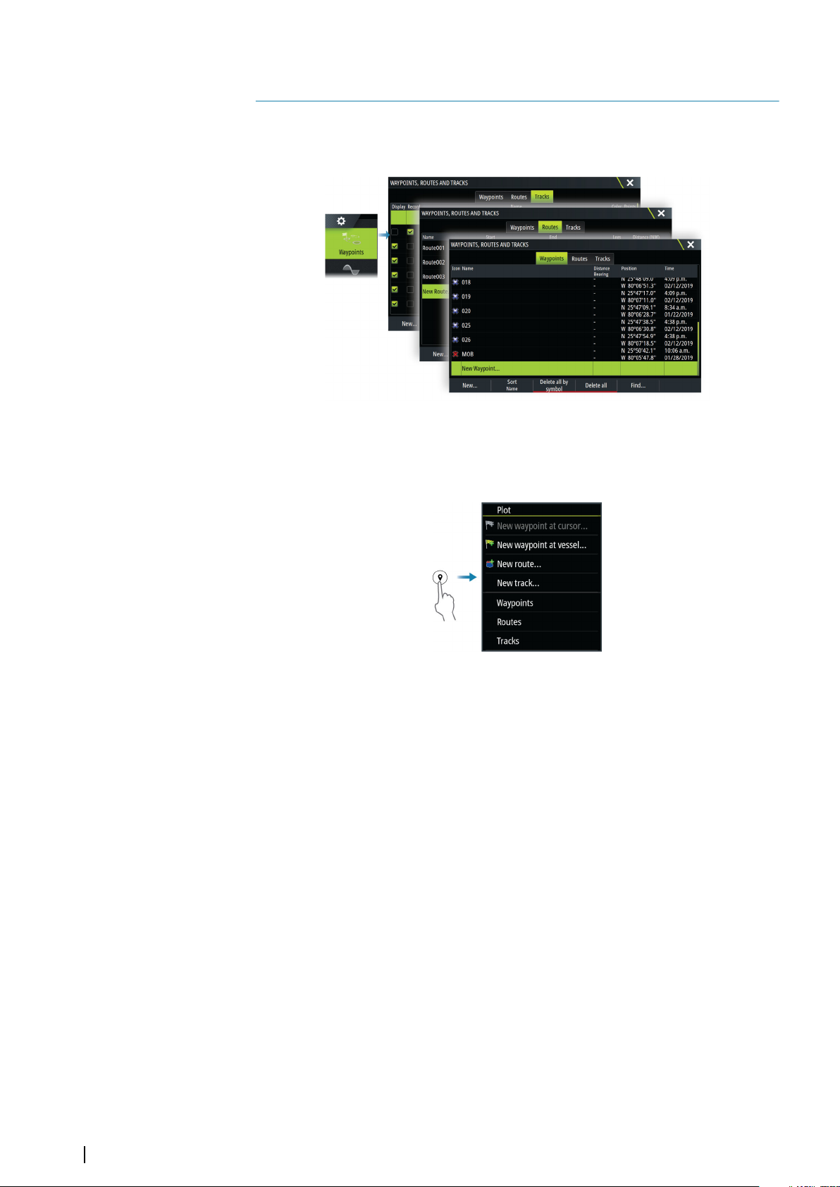
Waypoints, Routes, and Tracks dialogs
These dialogs give access to advanced edit functions and settings for these items.
The Plot dialog
Press and hold the waypoint key to open the Plot dialog. Select an option to add new or
manage existing waypoints, routes or tracks.
Waypoints
About waypoints
A waypoint is a user generated mark positioned on the:
• chart
• echosounder image
• radar image
Each waypoint has an exact position with latitude and longitude coordinates.
A waypoint positioned on the echosounder image has a depth value, in addition to position
information.
A waypoint is used to mark a position you later may want to return to. Two or more
waypoints can also be combined to create a route.
Saving waypoints
Save a waypoint at the cursor position if active or at the vessel's position if the cursor is not
active.
To save a waypoint:
• Press the rotary knob
• Press the Mark key
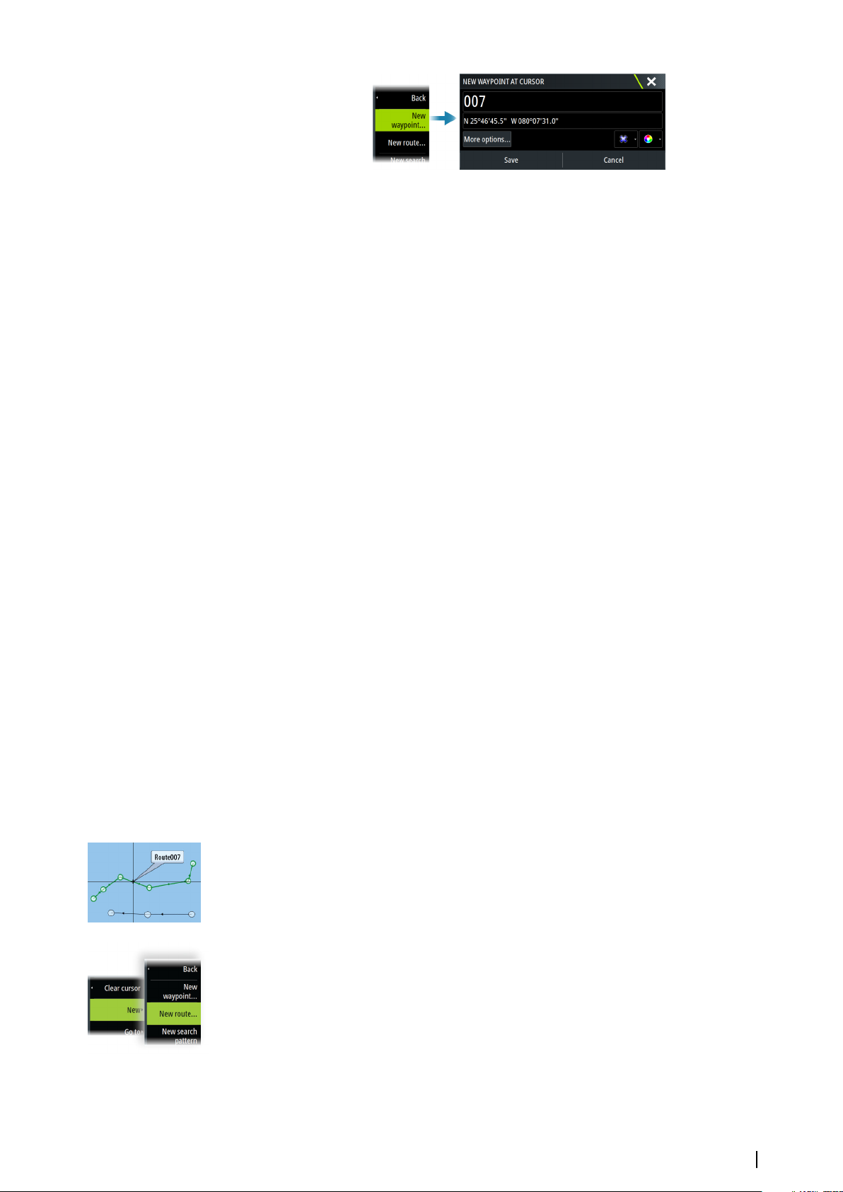
• Select the new waypoint option in the menu
36
Waypoints, routes, and tracks | Zeus³S Operation Manual
Page 37
Moving a waypoint
A waypoint can be moved from the position if active and if the waypoint is selected in the
menu.
To move a waypoint to a new position, select the move waypoint menu option and then
select the new waypoint location on the image.
To save the waypoint at the new position, select the finish moving menu option
Edit a waypoint
You can edit all information about a waypoint from the edit waypoint dialog.
The dialog is activated by selecting the waypoint, and then selecting edit from the menu.
The dialog can also be accessed from the waypoints tool on the home page.
Deleting waypoints
You can delete a waypoint by selecting the delete menu option when the waypoint is
activated on the panel.
You can also delete a waypoint by selecting it in the routes dialog and then deleting it in the
edit waypoint dialog.
You can delete all waypoints or waypoints by symbols from the system using the waypoints
dialog.
You can delete MOB waypoints the same way.
You can back-up your waypoints, routes and tracks before deleting them, refer to "Maintenance"
on page 128.
Waypoint alarm settings
You can set an alarm radius for each individual waypoint you create. The alarm is set in the
Edit Waypoint dialog.
Note: The waypoint radius alarm must be toggled ON in the alarm dialog to activate an
Ú
alarm when your vessel comes within the defined radius. For more information, refer to
"Alarm dialogs" on page 127.
Routes
About routes
A route consists of a series of routepoints entered in the order that you want to navigate
them.
When you select a route on the chart panel it turns green, and the route name is displayed.
Creating a new route on the chart panel
1. Activate the cursor on the chart panel
2. Select the new route option from the menu
3. Position the first waypoint on the chart panel
4. Continue positioning new routepoints on the chart panel until the route is completed
5. Save the route by selecting the save option in the menu.
Create a race route
A race route has waypoints with rounding indicators and a waypoint indicating the finish
line. When the race route is being followed, only the next rounding indicator is shown on the
Waypoints, routes, and tracks | Zeus³S Operation Manual
37
Page 38
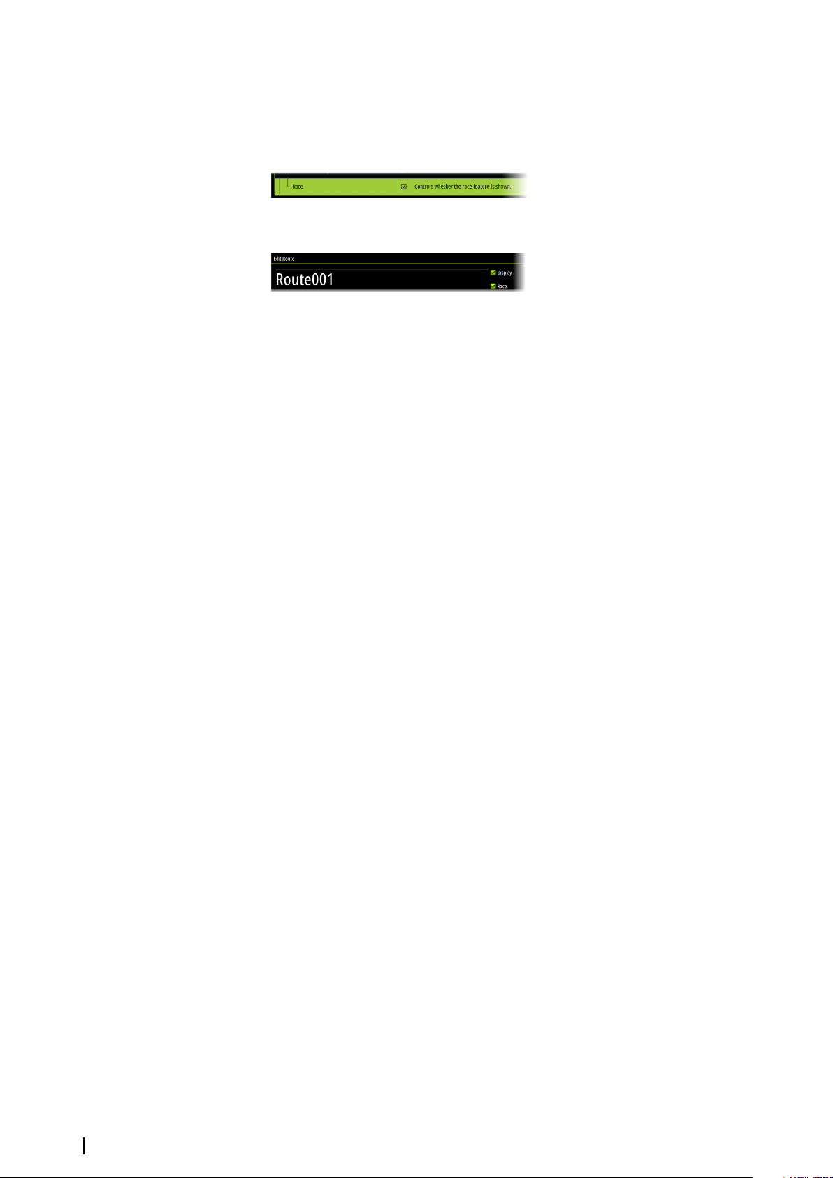
chart. The part of the route that has not been navigated is highlighted orange. When a part
of the route has been navigated it turns black.
To create a race route, do the following:
1. Turn on the race route feature by selecting the Race option in the Advanced Settings
dialog Features directory.
When the race route feature is selected, the Race mode option is available on the Edit
Route dialog.
2. Open the route in the Edit Route dialog, select the Race mode option, add rounding
indicators and specify a waypoint as the finish line. Refer to "Setting rounding indicators" on page
38. If you do not set the indicators, the system will add them based on what it thinks is
correct.
Setting rounding indicators
To set rounding indicators and indicate a waypoint as the finish line, edit the route using the
Edit Route dialog. When the race option is selected, the rounding column is available.
Once the rounding indicator and finish waypoint indicator are set they are shown on the
race route on the chart.
The current rounding setting is shown in the column for each waypoint in the race route.
Change the indicator for a waypoint by selecting one of the options in the drop-down list:
• Auto, auto determination of rounding
• Port, round to port
• Stbd, round to starboard
• Finish, waypoint is the finish line
Select Save to save your settings.
Edit a route from the chart panel
1. Select the route to make it active
2. Select the route edit option in the menu
3. Position the new routepoint on the chart panel:
-
If you set the new routepoint on a leg, a new point is added between existing
routepoints
- If you set the new routepoint outside the route, the new routepoint is added after the
last point in the route
4. Drag a routepoint to move it to a new position
5. Save the route by selecting the save option in the menu.
Note: The menu changes depending on the selected edit option. All edits are confirmed
Ú
or cancelled from the menu.
Creating routes using existing waypoints
A new route can be created by combining existing waypoints from the Routes dialog. The
dialog is activated by using the Waypoints tool on the Home page and then selecting the
Routes tab.
Routes - bulk insert waypoints
Use the bulk insert option to enter a list of waypoints separated by commas (for example
21,22,23,24) to create a new route or add multiple waypoints to an existing route.
1. Make a note of the waypoints you want to bulk enter. You do not have to enter the full
waypoint ID, just enough of it to distinguish it.
2. Select Routes on the Tool panel
3. Select the New button and then select the Create using route list option. Alternatively,
scroll down the list of existing routes and select New Route.
38
Waypoints, routes, and tracks | Zeus³S Operation Manual
Page 39
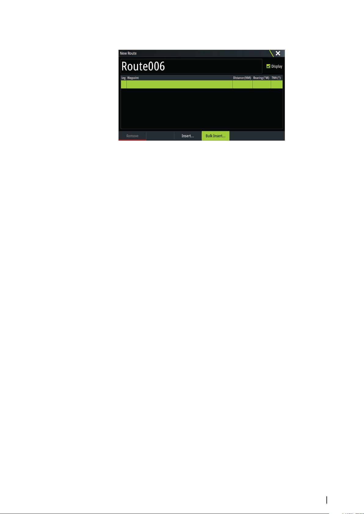
4. Select the first row in the New route dialog, so that it is highlighted
5. Select the Bulk Insert button
6. Enter a list of waypoints separated by commas (for example; 21,22,23,24). You can include
rounding indicators in the bulk entry by adding either .P (for Port) or .S (for Starboard) to
the waypoints (for example; 21.S, 22.P, 23.S, 24.P). The system changes the route to a race
route if rounding indicators are included in the bulk entry.
7. Select Enter. If the system finds more than one waypoint that has similar IDs, it will choose
one and advise you which one it has chosen. If the system does not find a waypoint with
a similar ID to what you entered, then a dialog opens and informs you of the items it did
not find.
8. (Optional) Give the route a name by selecting the system given name and use the virtual
keyboard to enter the name.
9. Select save.
Converting tracks to routes
You can convert a track to a route from the edit track dialog. The dialog is activated by
activating the track, and then:
• Selecting the track's pop-up
• Pressing the rotary knob
• Selecting the track in the menu
The edit track dialog can also be accessed by selecting the waypoints tool on the home
page.
Dock-to-dock Autorouting and Easy Routing
The Dock-to-dock Autorouting and Easy Routing suggest new routepoint positions based on
information in the map and on your boat's size. Before you can start using this feature the
boat draught, width and height must be entered into the system. The boat settings dialog is
automatically displayed if the information is missing when you start the feature. To enter
boat settings, refer to "System settings" on page 123.
Note: It is not possible to start the Dock-to-dock Autorouting or Easy Routing if one of
Ú
the selected routepoints is located in an unsafe area. A warning dialog is displayed, and
you have to move the relevant routepoint(s) to a safe area to proceed.
Note: If no compatible cartography is available, the Dock-to-dock Autorouting or Easy
Ú
Routing menu option is not available. Compatible cartography includes C-MAP MAX-N+,
Navionics+ and Navionics Platinum. For a full selection of available charts, visit
www.gofreemarine.com, www.c-map.com or www.navionics.com.
1. Position at least two routepoints on a new route, or open an existing route for editing.
2. Select the Dock-to-dock Autorouting menu option, followed by:
-
Entire Route - if you want the system to add new routepoints between the first and the
last routepoint of the open route.
- Selection - if you want to manually select the routepoints that define the limits for the
autorouting, then select the relevant routepoints. Selected routepoints are colored red.
Only two routepoints can be selected, and the system discards any routepoints
between your selected start and end points.
3. Select the accept option to start the automatic routing.
Waypoints, routes, and tracks | Zeus³S Operation Manual
39
Page 40
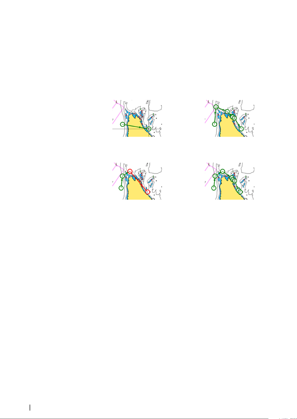
- When the automatic routing is completed the route appears in preview mode, and the
legs are color coded to indicate safe or unsafe areas. Navionics uses red (unsafe) and
green (safe), while C-MAP uses red (unsafe), yellow (dangerous) and green (safe).
4. Move any routepoints if required when the route is in preview mode.
5. Select the keep option to accept the routepoints positions.
6. Eventually repeat step 2 (selection) and step 3 if you want the system to automatically
position routepoints for other parts of the route.
7. Select the save option to complete the automatic routing and save the route.
Dock-to-dock Autorouting and Easy Routing examples
• Entire route option used when first and last route points are selected.
First and last routepoint Result after automatic routing
• Selection option used for autorouting part of a route.
Two routepoints selected Result after automatic routing
PredictWind weather and routing
For information about PredictWind weather and PredictWind routing, refer to "PredictWind" on
page 59.
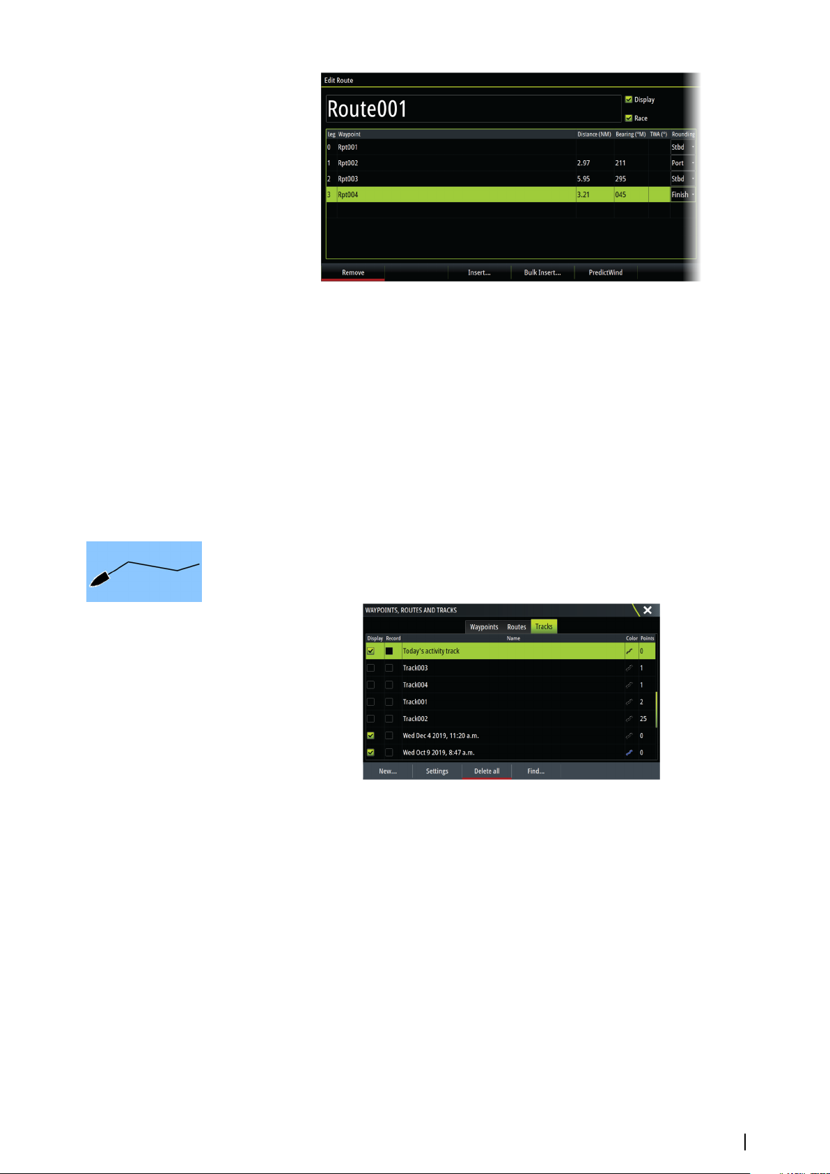
The edit route dialog
You can manage routes and routepoints, and change route properties using the Edit Route
dialog. This dialog is activated by selecting an active route's pop-up or from the menu by
selecting the route then the details option.
The dialog can also be accessed by using the Waypoints tool on the Home page and then
selecting a route in the dialog.
Select a routepoint in the edit dialog to insert a new routepoint after it or remove the
routepoint.
When adding routepoints, you can insert bulk waypoints. You can also use the bulk insert
option to insert route race waypoints with rounding indicators. Refer to "Routes - bulk insert
waypoints" on page 38.
Select the display option to show the route on the chart.
Select Race to convert the route to a race route and edit the rounding indicators on route
waypoints. Refer to "Setting rounding indicators" on page 38. If it is a race route, the system will add
the rounding indicators to what it thinks is correct based on the angles.
40
Waypoints, routes, and tracks | Zeus³S Operation Manual
Page 41
Deleting routes
You can delete a route by selecting the delete menu option when the route is activated on
the panel.
You can also delete a route by selecting it in the routes dialog and then deleting it in the edit
route dialog.
You can delete all routes from the system using the routes dialog.
You can back-up your waypoints, routes and tracks before deleting them, refer to "Maintenance"
on page 128.
Tracks
About tracks
Tracks are a graphical presentation of the historical path of the vessel. They allow for
retracing where your boat has travelled.
Example of the Tracks dialog:
Recording and displaying tracks
When the recording of a new track is started, the old one is hidden to de-clutter the chart
panel. If Display is enabled on the old track, it will continue to show on the chart panel.
Note: To display tracks on the chart panel, both the Display option in the Track dialog
Ú
and the Tracks option in the Chart settings dialog have to be enabled.
Creating a new track
You can start a new track from the Tracks dialog. The dialog is activated by:
• Using the Waypoints tool on the Home page and selecting the Tracks tab.
• Selecting the New track or Tracks option on the Plot dialog.
• Selecting the Tracks option in the chart menu.
Waypoints, routes, and tracks | Zeus³S Operation Manual
41
Page 42
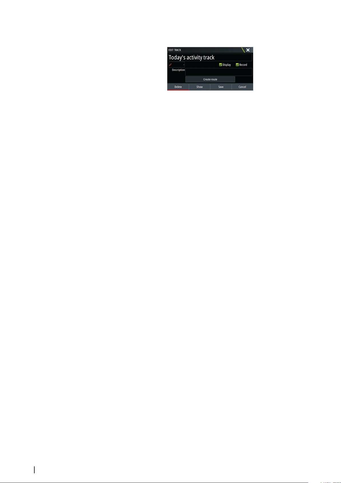
The edit tracks dialog
You can manage a track and change a track's properties using the edit track dialog. This
dialog is activated by selecting a track's pop-up or by selecting the track in the chart menu.
The dialog can also be accessed by using the Waypoints tool on the Home page and then
selecting a track in the Tracks dialog.
Coloring tracks
To color tracks:
• Select the track in the Tracks dialog and set the color for the entire track in the Edit Track
dialog.
• Select to let the system color the track based on source data and high/low settings. Refer
to "Color tracks based on data" on page 25.
Deleting tracks
You can delete a track by selecting it in the tracks dialog and then deleting it in the edit track
dialog.
You can delete all the tracks from the system using the tracks dialog.
You can back-up your waypoints, routes and tracks before deleting them, refer to "Maintenance"
on page 128.
Track logging settings
Tracks are made up of a series of points connected by line segments whose length depends
on the frequency of the recording.
You can select to position track points based on time settings, distance, or by letting the
system position a waypoint automatically when a course change is registered.
The logging settings can be made from the Tracks settings dialog or by selecting the Settings
button in the Tracks dialog.
C-MAP Embark
You can access the C-MAP Embark web site from a PC or use the C-MAP Embark app on your
smart device to manage:
• waypoints
• routes
• tracks
Use the unit's C-MAP Embark feature to synchronize between the unit and C-MAP Embark.
Note: PredictWind waypoints are not included in the C-MAP Embark feature.
Ú
Requirements
• An account with C-MAP Embark
• To synchronize, the unit must be connected to the internet.
42
Synchronizing
To synchronize the MFD and C-MAP Embark, open the C-MAP Embark feature from the
System Controls dialog or the Services settings dialog.
After sign-in, the system advises the last time synchronizing occurred and the following
options are available:
Waypoints, routes, and tracks | Zeus³S Operation Manual
Page 43
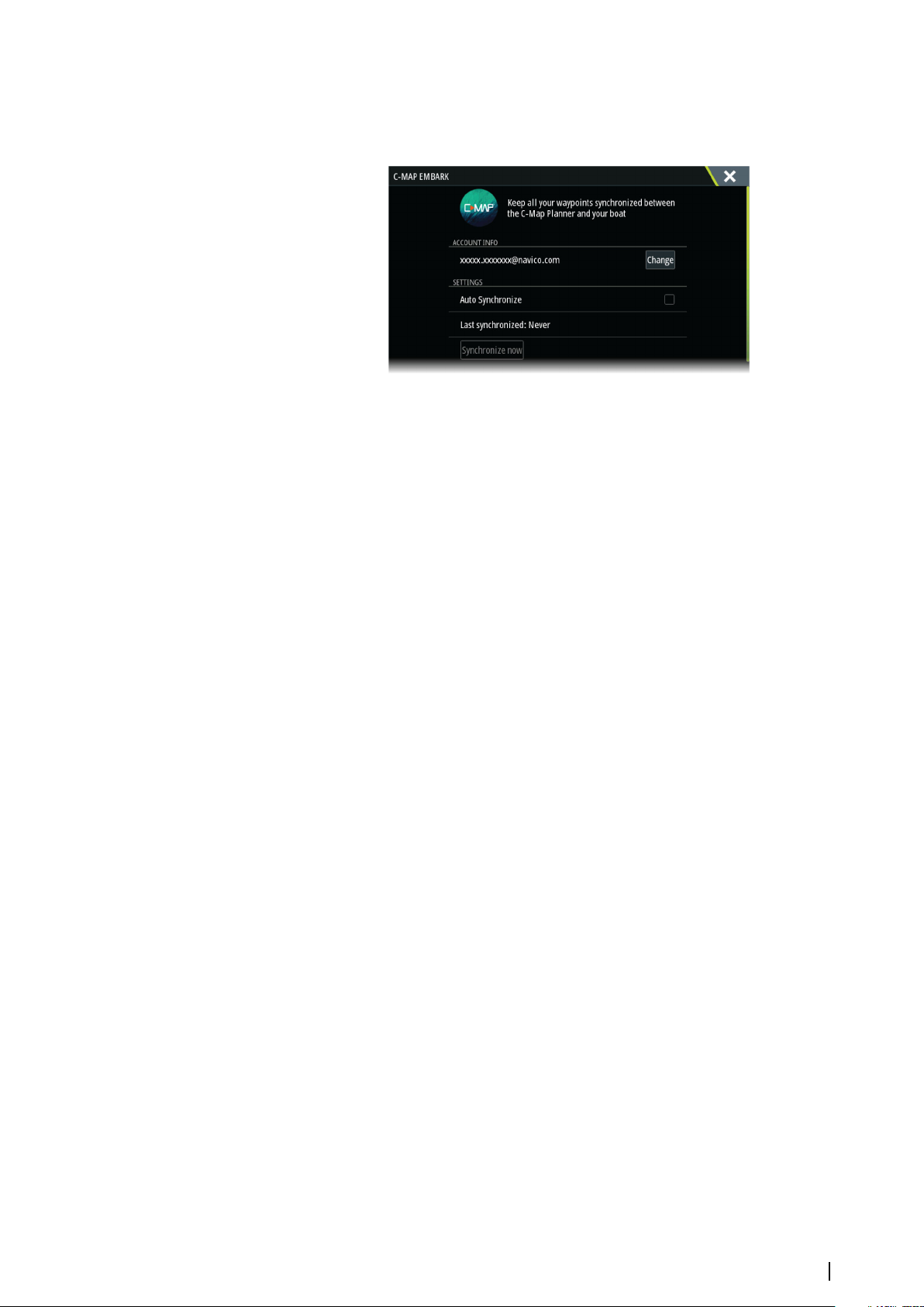
• Change - use to change sign-in credentials
• Auto Synchronize - synchronizing occurs periodically in the background when connected
to the internet
• Synchronize now - synchronizing occurs immediately
Waypoints, routes, and tracks | Zeus³S Operation Manual
43
Page 44
Navigating
6
About navigating
The navigation function included in the system allows you to navigate to the cursor position,
to a waypoint, or along a predefined route.
If autopilot functionality is included in your system, the autopilot can be set to automatically
navigate the vessel.
For information about positioning waypoints and creating routes, refer to "Waypoints, routes, and
tracks" on page 36.
Navigate to cursor position
You can start navigating to a cursor position on any chart, radar, or echosounder panel.
Position the cursor at the selected destination on the panel, and then select the go to cursor
menu option.
Note: The go to cursor menu option is not available if you are already navigating.
Ú
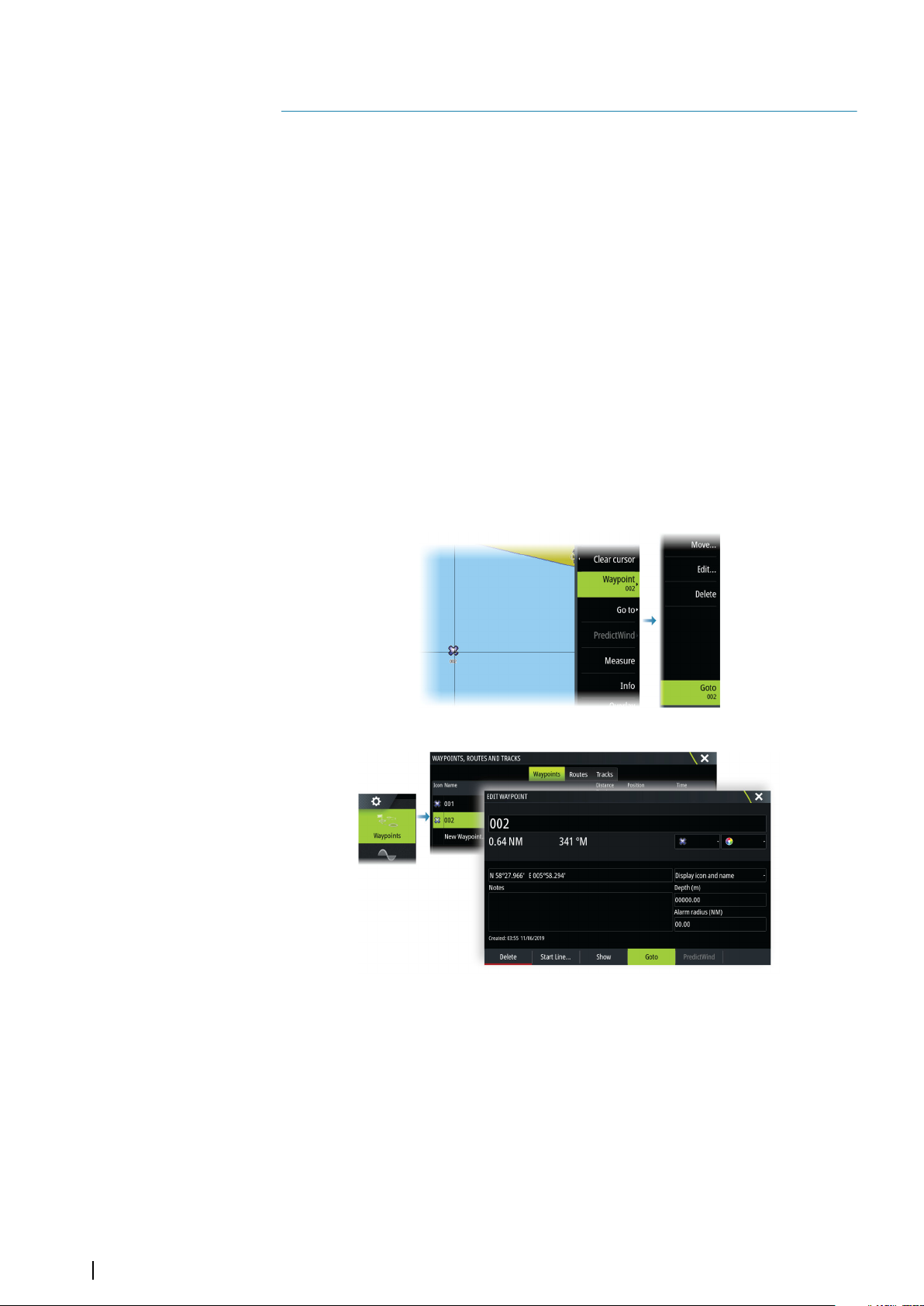
Navigating to a waypoint
You can navigate to a waypoint:
• from a chart
• using the waypoint dialog
When navigating to a waypoint, the menu expands and shows options for canceling and for
restarting the navigation from current vessel position.
Navigating a route
You can start navigating a route from:
• the chart panel
44
Navigating | Zeus³S Operation Manual
Page 45
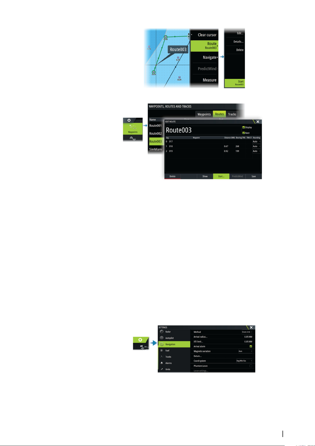
• the route dialog
When route navigation is viewed, the menu expands and shows options for canceling the
navigation, for skipping a waypoint, and for restarting the route from current vessel position.
Starting a route from the chart panel
Activate a route on the panel, and then select the route navigation option from the menu.
You can select a routepoint to start navigating from a selected position.
Navigating with the autopilot
When you start navigation on a system with autopilot functionality, you are prompted to set
the autopilot to navigation mode.
Note: The prompt to set the autopilot to navigation mode is disabled if the boat type is
Ú
set to SAIL in the Autopilot Commissioning dialog.
If you choose not to engage the autopilot, the autopilot can be set to navigation mode from
the Autopilot Controller later on.
For more information about autopilot functionality, refer to the autopilot chapter of the
autopilot being used.
Navigation settings
Navigation method
Different methods are available for calculating the distance and bearing between any two
geographical points.
Navigating | Zeus³S Operation Manual
45
Page 46
The Great circle route is the shortest path between two points. However, if you are to travel
along such a route, it would be difficult to steer manually as the heading would constantly
be changing (except in the case of due north, south, or along the equator).
Rhumb lines are tracks of constant bearing. It is possible to travel between two locations
using Rhumb line computation, but the distance would usually be greater than if Great circle
is used.
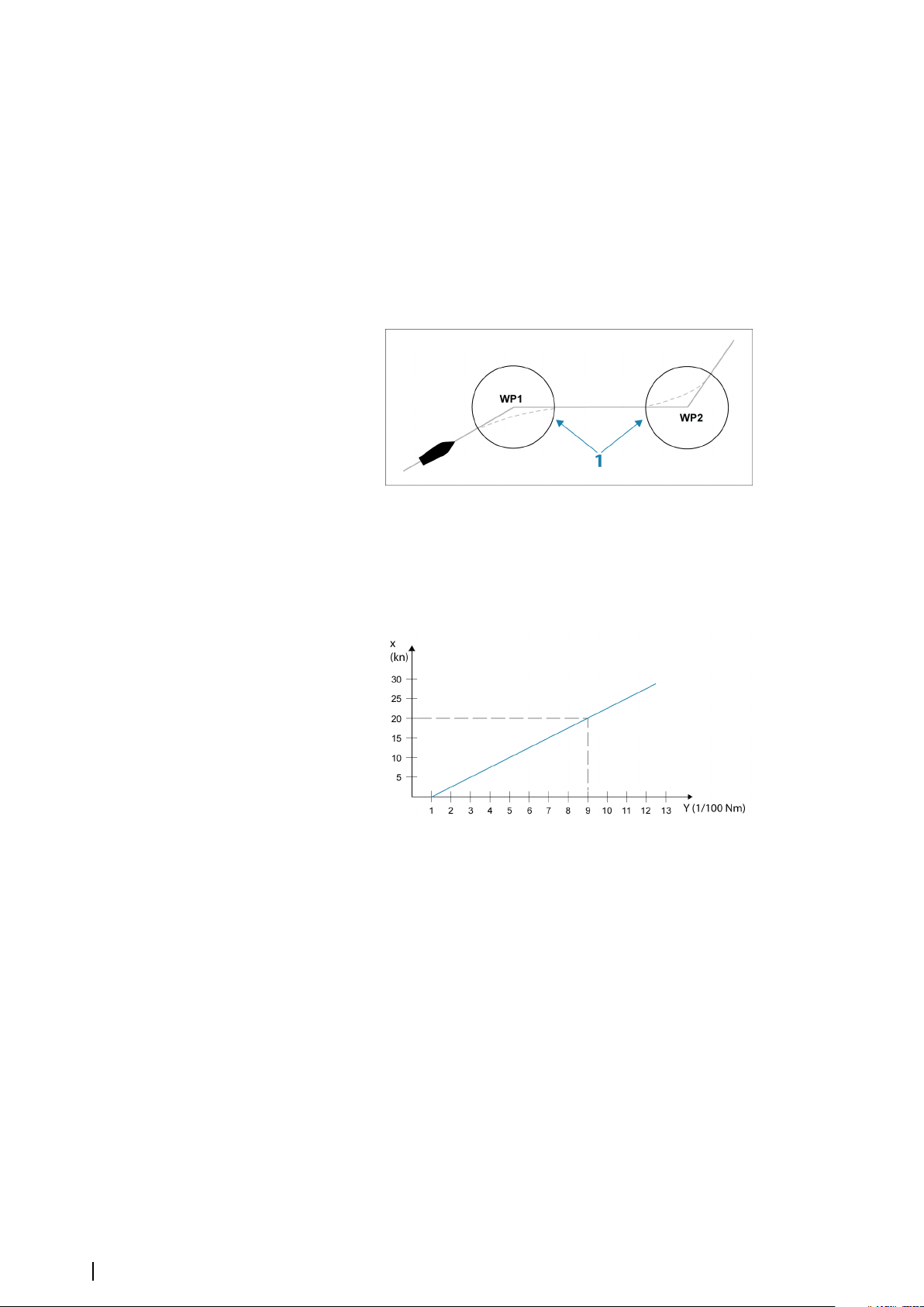
Arrival radius
Sets an invisible circle around the destination waypoint. The vessel is considered arrived at
the waypoint when it is within this radius.
When you are navigating a route, the arrival radius defines the point at which a turn is
initiated.
The arrival circle (1) should be adjusted according to boat speed. The higher the speed, the
wider the circle.
The intention is to make the autopilot start the heading change in due time to make a
smooth turn onto the next leg.
The figure below may be used to select the appropriate waypoint circle when creating the
route.
46
Note: The distance between any waypoints in a route must not be smaller than the
Ú
radius of the waypoint arrival circle.
XTE limit
Defines how far the vessel can deviate from the selected route. If the vessel goes beyond this
limit, an alarm is activated.
Arrival alarm
When the arrival alarm is enabled, an alarm is activated when the vessel reaches the
waypoint or when it is within the specified arrival radius.
Magnetic variation
Magnetic variation is the difference between true bearings and magnetic bearings, caused
by different locations of the Geographic and the Magnetic north poles. Any local anomalies
such as iron deposits might also affect the magnetic bearings.
When set to Auto, the system automatically converts magnetic north to true north. Select
manual mode if you need to enter your own local magnetic variation.
Navigating | Zeus³S Operation Manual
Page 47
Datum
This system uses the WGS datum format, which is a standard for use in cartography and
satellite navigation (including GPS).
You can change the datum format to match other systems.
Coordinate system
Used to set the geographic coordinate system used on your system.
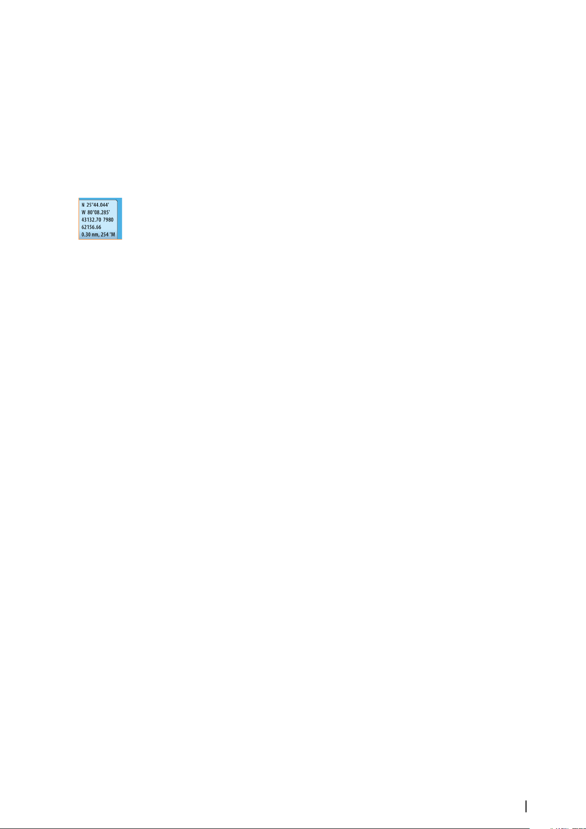
Phantom Loran
Enables use of Phantom Loran positioning system.
Defines Loran chains (GRI) and preferred station for waypoint entry, cursor position and
position panel.
The graphic example shows a cursor position window with Loran position information.
For more information refer to your Loran system documentation.
Navigating | Zeus³S Operation Manual
47
Page 48
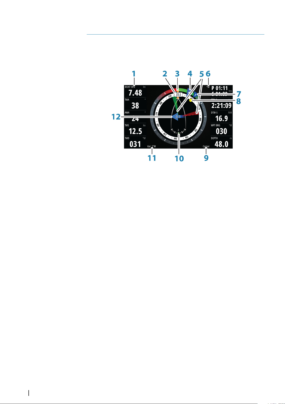
7
SailSteer panel
The SailSteer panel provides a composite view of key sailing data. All data is displayed relative
to the yacht’s bow, providing a clear and easy to understand image of important sailing data.
The SailSteer panel can be shown as a full screen panel, or in a multi-panel page.
The number of data fields included in the panel is dependent on available panel size.
1 User configurable data fields
2 Vessel heading
3 COG (Course Over Ground)
4 Apparent wind*
5 Port and starboard laylines.
6 Magnetic or True reference
7 TWA (True Wind Angle) - Green if on TWA upwind or downwind. Blue if off target
by 10º or more, or on a free leg. The indicator will fade from blue to green the
closer you get to the exact angle.*
8 Bearing to current waypoint
9 Active (next) waypoint ID, routepoint ID, or cursor
10 Rudder angle
Note: Only visible if a valid rudder source is available on the system.
Ú
11 Magnetic variation
12 Tide rate and relative direction*
* Optional images. You can turn the optional images on/off from the menu.
Selecting data fields for the SailSteer panel
Data sources connected to the system can be viewed on the SailSteer panel.
1. Select the SailSteer panel to make it active.
2. Select the MENU button and select the edit option.
-
Edit mode is indicated in top of the panel.
3. Select the instrument field you want to change.
- The selected field has a highlighted frame.
4. Select the MENU button again to select info.
5. Repeat the steps to change other instrument fields.
6. Save your settings by selecting the save option in the menu.
48
SailSteer panel | Zeus³S Operation Manual
Page 49
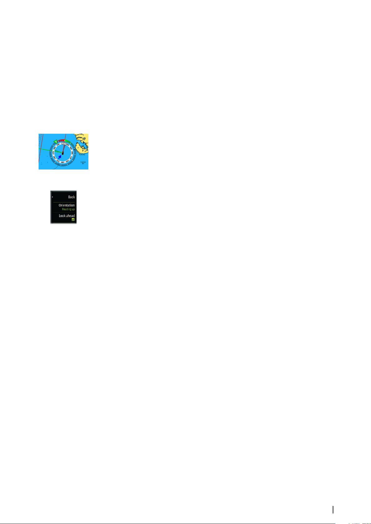
Sail Time calculations
The system calculates the time and distance to a waypoint taking into consideration that the
vessel is sailing on a layline course to the waypoint. Data showing time calculations will be
indicated with an -S extension:
DTW-S Sailing Distance to Waypoint
TTW-S Sailing Time to Waypoint
ETA-S Sailing Estimated Time of Arrival
SailSteer overlay
You can overlay the SailSteer image on the Chart. You toggle the SailSteer image overlay on
and off in the Chart setting dialog.
Note: If both the SailSteer image and autopilot compass overlays are enabled then only
Ú
the SailSteer overlay is shown.
Note: SailSteer overlay is not shown when the cursor is activate or when panning the
Ú
chart. Select the clear cursor option to display the SailSteer overlay again.
Note: If the Look ahead menu option is selected, then the Heading up orientation
Ú
must also be selected in order to display the SailSteer overlay. If the Look ahead menu
option is not selected, then the SailSteer overlay is displayed with all the orientation
settings: North up, Heading up, and Course up.
SailSteer panel | Zeus³S Operation Manual
49
Page 50
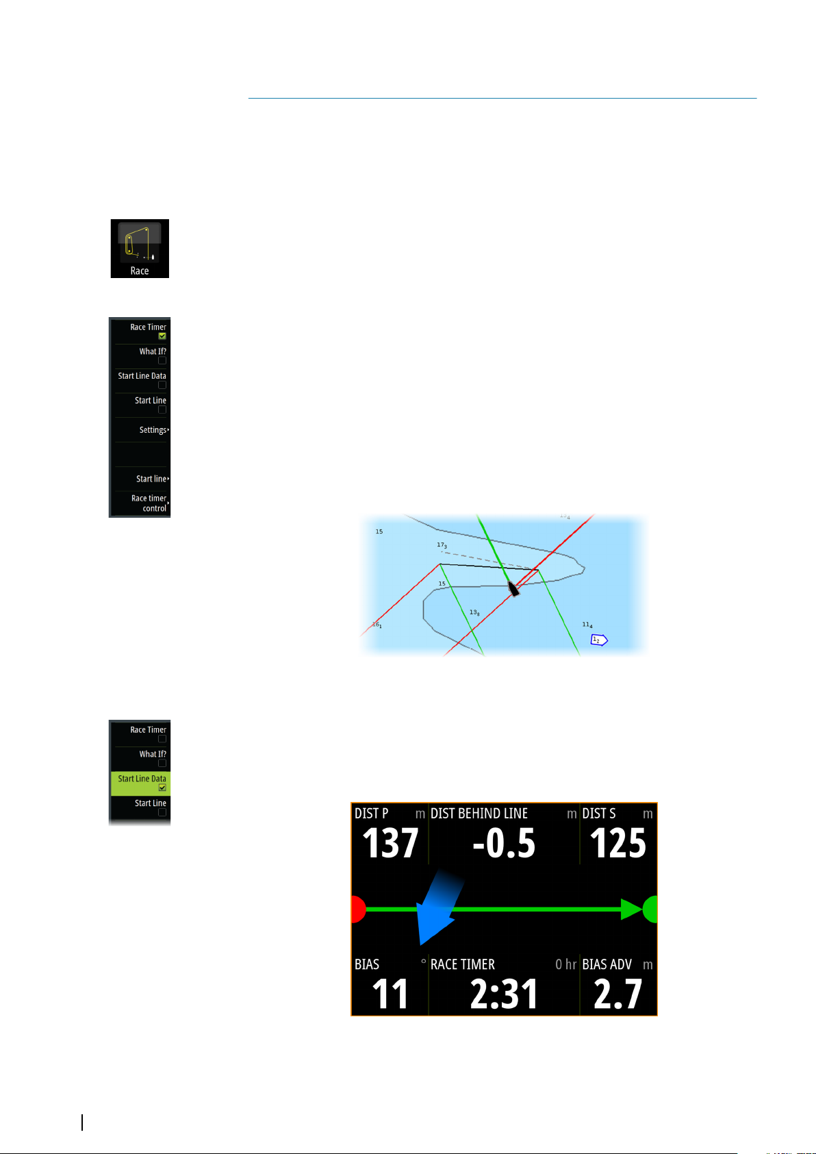
8
Race panel
Use the Race panel to:
• Display and control the race timer
• Create and manage the race start line
• Display race start line data
• Display the race start line in a chart diagram on the Race panel
• Display tactical information for the current leg or next leg
Select the Race button on the Home page to display the Race panel.
Display options
Use the Race panel menu to specify if you want to display the Race Timer, What if? data, Start
Line Data, or Start Line display (display the boat and start line in graphical format).
Start Line on Chart panel
You can display a race start line overlaid on the Chart panel. The start line data can be
displayed in the Instrument page. If you have an H5000 CPU on your network, start line data
is calculated by the H5000 CPU. Otherwise the data is calculated in the MFD.
Viewing the start line on the chart panel allows the navigator to assess around the starting
area for hazards. Use the laylines to see where the likely tracks into and out of the starting
area will be relative to the chart data.
The solid black line indicates the start line (between the two starting marks) on the chart
panel. You can switch off the start line overlaid on the Chart if desired.
Start Line Data panel
Select the Start Line Data menu option to show the Start Line Data panel. The Start Line
Data panel shows start line data and a graphical representation of the start line. It displays
boat distance from the start line, tide direction, recommended start end bias and what
advantage in degrees and distance the biased end will give.
50
Race panel| Zeus³S Operation Manual
Page 51
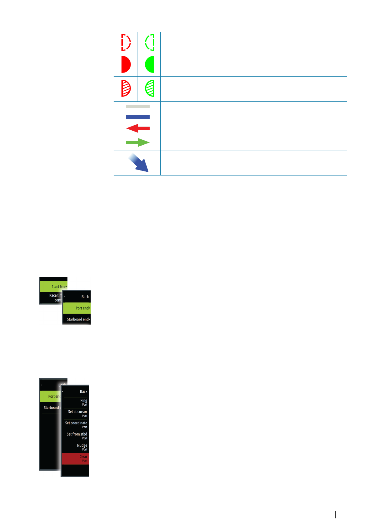
Start line end not set (position not recorded)
Start line end set (position recorded)
Start line end stale (historic start line position)
Start line end becomes stale at 23:59 hrs on the day it was recorded but
remains valid.
Invalid start line - One or more ends invalid (position not recorded)
Start line - Blue - Square line - No bias advantage
Start line - Red & Arrow left - Port end bias
Start line - Green & Arrow right - Starboard end bias
Tide direction indicator
Data displayed on start line panel
The following data is displayed on the start line panel:
• DIST P - Distance to port end of start line
• DIST BEHIND LINE - Distance to start line (perpendicular)
• DIST S - Distance to starboard end of start line
• BIAS - Start line bias angle
• RACE TIMER - Time on the race timer
• BIAS ADV - Bias advantage (meters or boat lengths)
Setting up a start line
The start line is a visual aid that shows the distance from the boat to the start line, tide
direction, recommended start end bias, and what advantage in degrees and distance the
biased end will give. The start line is a line between the port and starboard end points.
Note: If you have an H5000 CPU on your network, the start line information between the
Ú
MFD and the H5000 is shared. The start line data numbers are calculated on the H5000
CPU and sent across the network. There is only one start line. If you set the start line on
the MFD, it will show on the H5000 Graphic Display and vice-versa.
Note: Before setting the start line position it is important that the GPS Bow offset is
Ú
updated to negate the difference between the GPS position and the bow of the vessel.
This setting is made in the Advanced settings dialog under Instruments. Your Boat
settings must also be entered in the Boat settings dialog which is available from the
Chart settings dialog.
Menu options let you use different methods for setting the port and starboard start line ends.
You can ping them, set them at cursor position, specify coordinates, and set one based on the
setting of the other. You can also edit waypoints to create start line end points. After the
ends are set you can nudge each end to move them, if needed.
The menu options to set the port and starboard start line end points are available in both the
Chart panel and the Race panel.
Setting start line end points by pinging
Setting the start line end points by pinging requires maneuvering the boat to each end of
the start line and then pinging.
Note: Before setting the start line position using the ping method, it is important that
Ú
the Bow offset is updated to negate the difference between the GPS position and the
bow of the vessel.
Race panel| Zeus³S Operation Manual
51
Page 52
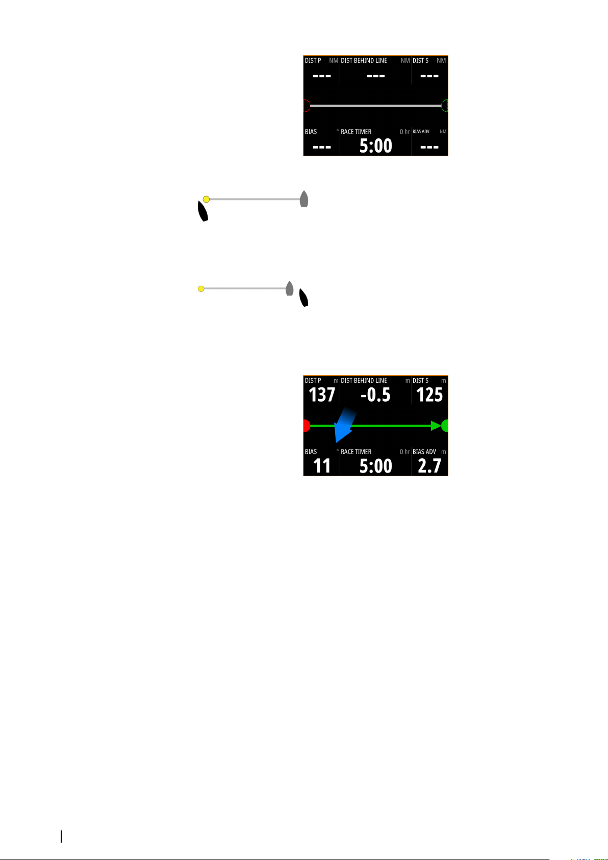
1. Approach the port end of the start line.
2. When the boat reaches the port end of the start line, open the menu and select Start
Line, Port end, and then Ping port. The port end mark on the start line panel becomes
solid red, indicating it is set.
3. Approach the starboard end of the start line.
4. When the boat reaches the starboard end of the start line, open the menu and select
Start Line, Starboard end, and then Ping Starboard. The starboard end mark on the
start line panel becomes solid green indicating it is set.
The start line end points are set and can be viewed on the Chart panel and Start line panel.
Setting end points at cursor position
1. Open the Chart panel and move the cursor to the position in the chart where you want
the port end point to be.
2. Open the menu and select Start line, Port end, and then Set at cursor.
3. Repeat steps 1 and 2 for the starboard end point.
The start line end points are set and can be viewed on the Chart panel and Start line panel.
Setting end points at coordinates
Select the Set coordinate Port and then the Set coordinate Starboard menu options to
enter the coordinates of the port and starboard end points.
Setting end points from each other
Use the Set from stbd Port and Set from port Starboard menu options to set the Range
and Bearing of the end points from each other.
Removing end points and the start line
Use the Clear Port or Clear Starboard menu options to remove the start points. When
both are removed, the start line is removed.
52
Race panel| Zeus³S Operation Manual
Page 53
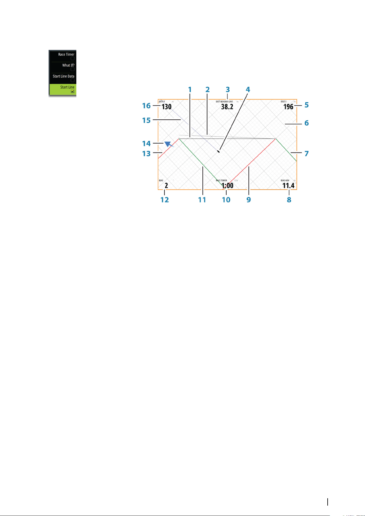
Start Line display
Select the Start Line menu option to show the Start Line display in the Race panel. The Start
Line display shows the configured start line in scale with your boat, allowing you to clearly
see distance to line and position relative to the laylines. All start settings are also shown on
this display.
1 Start line
2 Square wind line - drawn from biased start line end perpendicular to True Wind
Direction
3 Distance (perpendicular) behind line
4 Boat (drawn to scale)
5 Distance to starboard end of start line
6 Grid
7 Starboard tack layline to the starboard start line end point
8 Advantage gained by starting at favored end
9 Port tack layline to the starboard start line end point
10 Race Timer
11 Starboard tack laylines to the port start line end point
12 Start Line bias angle
13 Port tack laylines to the port start line end point
14 Tide arrow (relative to start line)
15 Extension line
16 Distance to port end of start line
In addition, when a target boat speed is available (from the Hercules Polar table, laylines
targets table, or manual setting in the Laylines setup, refer to "Laylines" on page 33) a Zero Burn
line may be shown, parallel with the start line, which indicates the distance you should be
from the starting line as time counts down.
Race panel| Zeus³S Operation Manual
53
Page 54
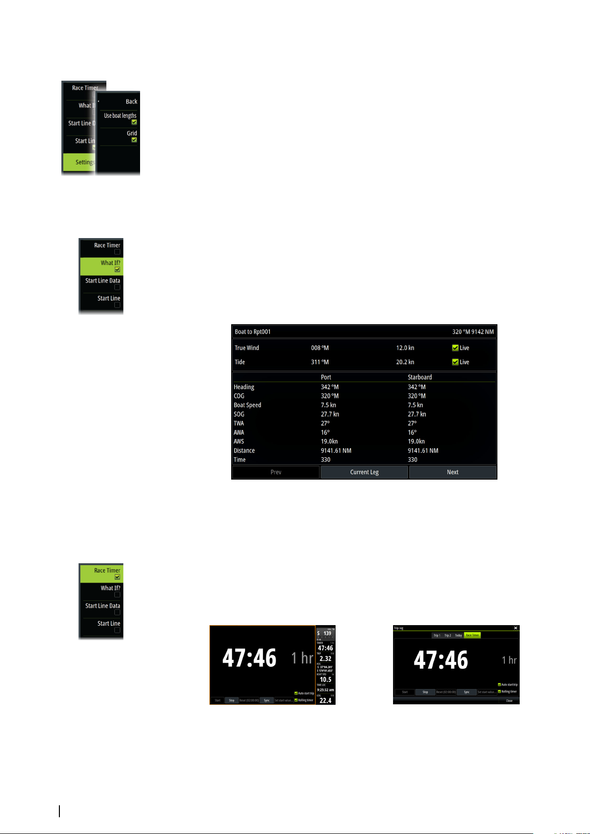
Settings
Boat lengths
Select the Use boat lengths setting to show the distance behind the line and Bias
advantage in boat length data measurements on the Start line panel. Showing the
measurements in boat lengths can give a clearer indication of the distance from your boat to
the start line.
Show layline grids
Select Grid to show layline grids in the start line diagram. The grid is a background that is
aligned with the laylines. They can give a clearer indication of possible runs to the start line.
What if?
Select the What if? in the menu to display navigation data in the Race panel and to change
variables to see what could happen. This is a tool for assessing potential changes in wind or
tide in current and future legs of the course.
Deselect Live and enter parameters for the wind, tide, or both to see how data might
change for the leg. For example, if you can see the sea breeze building in with boats sailing
different angles on the horizon, you can enter this data to estimate the effect.
Race timer
The race timer can be used to countdown to zero from a specified time, ideal for counting
down to a race start. It can also be used to count up from zero to record the elapsed time.
You can start and stop the timer, reset it, sync it, and specify a start value.
You can display the Race timer from the Race panel menu, or by selecting Trip Calculator
from the Tools panel.
The Timer set value is in hh:mm, the timer counter shows in mm:ss, with the hours showing
to the right of the minutes and seconds.
Race timer panel
Race Timer in the Trip Log
54
Race panel| Zeus³S Operation Manual
Page 55
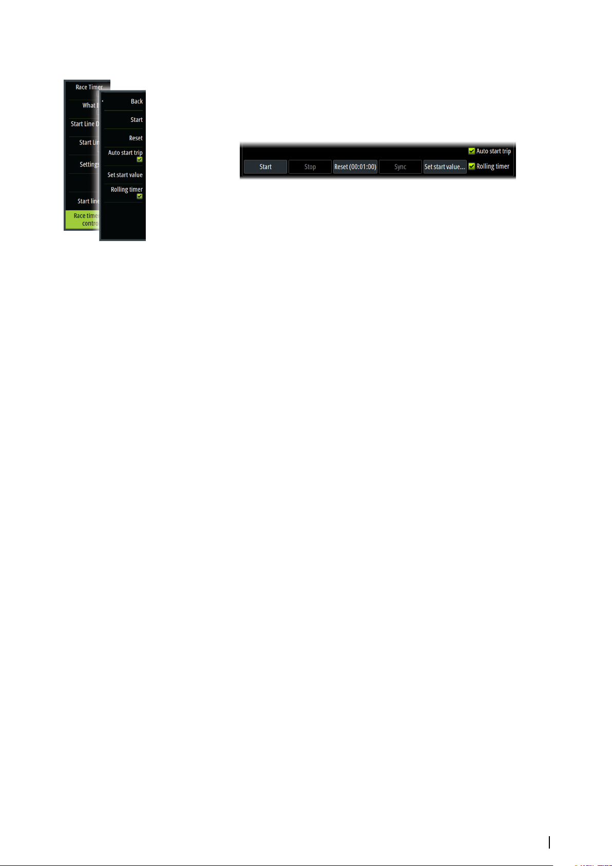
Race timer controls
You can access Race timer controls from the Race panel menu. You can also access them at
the bottom of the Race timer panel displayed from the Home page and the Race timer panel
displayed from the Trip Calculator (Tool panel). Different controls are enabled depending on
if the timer is started or stopped.
Set start value
Set a time value which the timer shall use to count down to the start time of the race. The
timer starts counting down when you select Start.
Start/Stop timer
The timer can be started at any time by selecting Start. If a time value is preset, the timer
counts down. If the start value is set to zero (00:00) when the timer is started, the timer
begins counting up, recording the elapsed time.
To stop the timer from counting select Stop.
Reset
Resets the timer to the start value. If the timer is running when Reset is selected, it continues
to run from the start value.
Sync
When the timer is counting down selecting Sync synchronizes the time up or down to the
nearest full minute.
Auto start trip
When Auto start trip is selected, the Trip Log records your time and mileage from the
moment the countdown timer begins counting up from zero.
Rolling timer
When Rolling timer is selected, the timer restarts the countdown timer every time it
reaches zero. It continues to do this until the timer is stopped.
Race panel| Zeus³S Operation Manual
55
Page 56
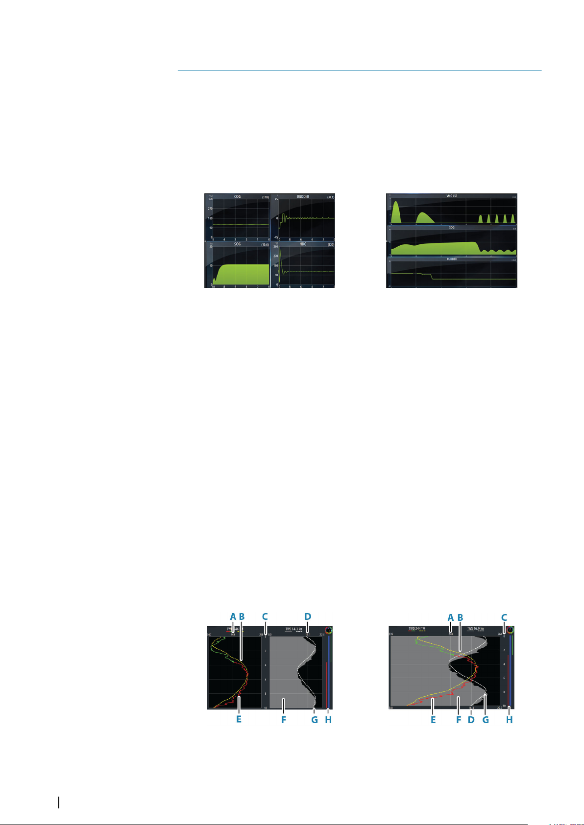
9
Time and Wind plots
The system can present data history in different plots. The plots can be displayed in full page,
or combined with other panels.
The Time plot panel
The Time plot panel consists of two predefined layouts. You switch between the layouts by
selecting the left and right panel arrows. You can also select the layout from the menu.
You can select which data to present on a time plot panel, and you can define the time
range for each plot.
Layout 1
Missing data
If the data is unavailable, the relevant plot turns into a dashed line and flattens out at the
point the data was lost. When the data becomes available again, a dashed line joins up the
two points showing an average trend line bridging the missing data.
Selecting data
Each data field can be changed to show the preferred data type and the time range.
1. Select the edit option from the menu
2. Activate the field you want to edit
3. Change the information type and eventually the range
4. Save your changes
The data available for the Time plots are by default the sources used by the system. If more
than one data source is available for a data type you can select to show alternative data
source in the Time plot. You change the data type by using the data source option in the
menu.
Layout 2
The Wind Plot panel
A Wind Plot is a special type of Time Plot specifically designed to help understand recent
changes in wind speed and direction.
The Wind Plot can be displayed as a dual or combined view.
In the plots, X axis = degrees and Y axis = minutes.
56
Dual view Combined view
A True Wind Direction (TWD) average*
Time and Wind plots| Zeus³S Operation Manual
Page 57
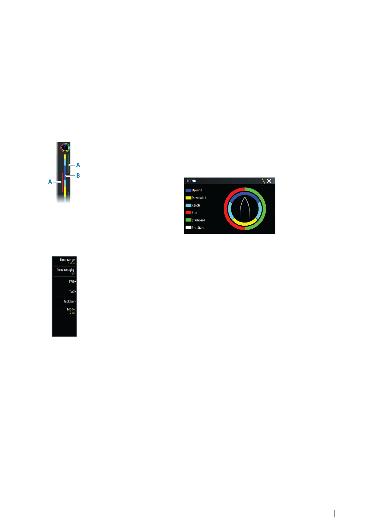
B TWD trend*
C Time range
D True Wind Speed (TWS) average*
E TWD plot
F TWS plot
G TWS trend*
H Tack bar*
* Optional items. Optional items can be turned on/off individually from the Wind Plot panel
menu.
Tack bar
The tack bar shows which tack you are currently sailing on (A) and a point of sail/pre-start
status bar (B) corresponding to the data recorded at the time. Tack bar data uses the same
time scale as the main Wind Plot window.
Select the tack bar to view the tack bar legend.
Setting up the page
Use the Wind Plot panel menu to set up the page.
Time range
Sets the time range interval.
Trend averaging
Sets the amount of averaging applied to the Trend line. A low setting shows the highest
detail (closest to the raw data, lowest amount of damping), and a high setting shows a
smoother trend (highest amount of damping). A medium setting is a good balance between
raw and damped data.
TWD options
Display options
Sets the plot to show TWD only, TWD trend only or both the TWD and trend.
Average line
Shows or hides the TWD average line (calculated over the time range) on the plot image.
Tack colors
Select to show the TWD in starboard (green) or port (red) colors depending on the current
wind angle or unselect to show the TWD as a constant (blue) color.
TWS options
Display options
Sets the plot to show TWS only, TWS trend only or both the TWS and trend.
Average line
Shows or hides the TWS average line (calculated over the time range) on the plot image.
Time and Wind plots| Zeus³S Operation Manual
57
Page 58
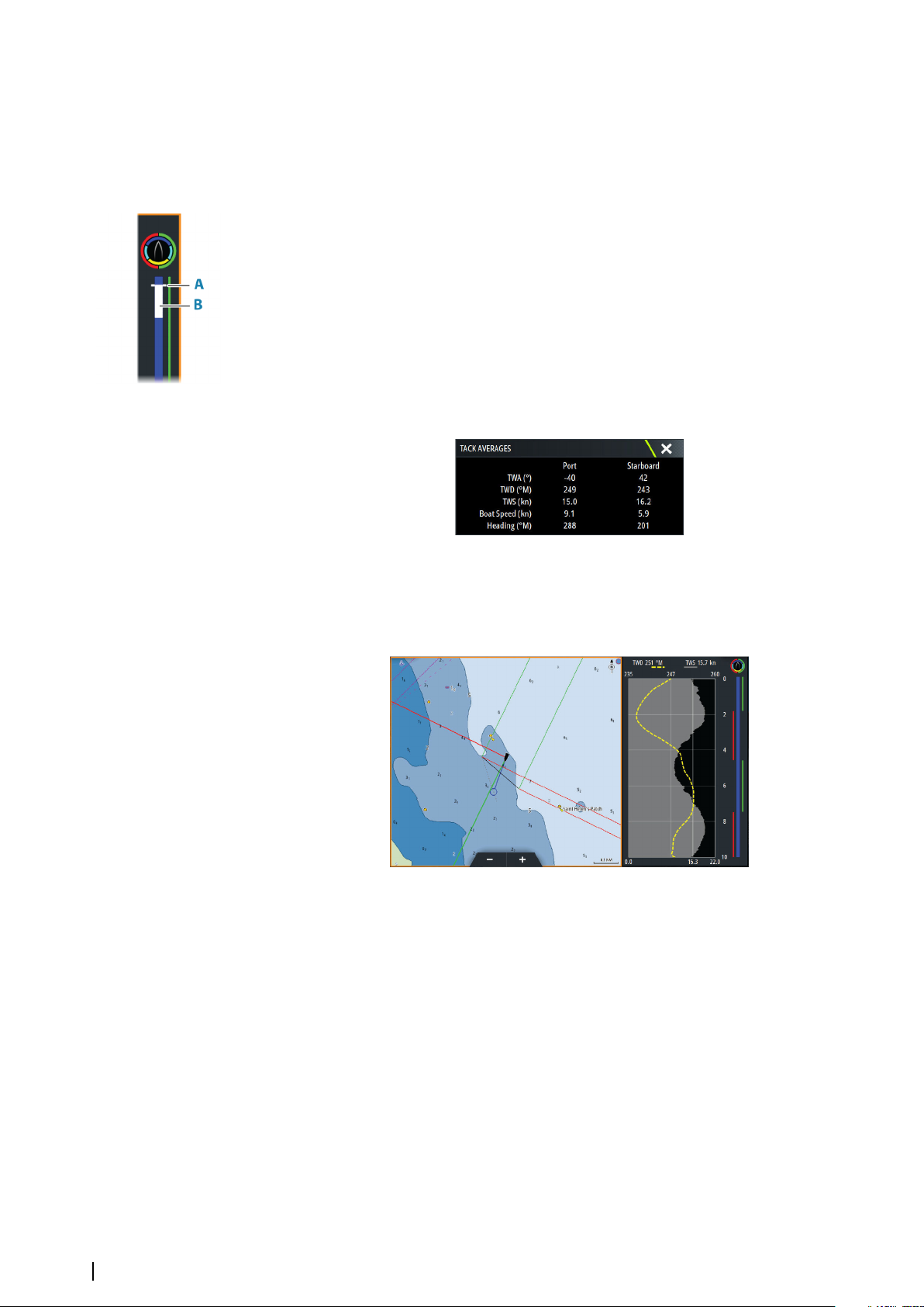
Tack bar option
Show
Shows or hides the tack bar.
Start line
Shows or hides the race start line on the tack bar.
The start line is only shown on the tack bar when it is enabled, and when the race timer is
started and counting down to zero.
When the start line is enabled and the race timer is started, the white line (B) on the tack bar
represents the race timer. The tack bar shows the start line as a horizontal line (A) across the
tack bar representing the time the race timer will reach zero. When the race timer reaches
zero the white line will change to the appropriate color according to your point of sail.
Tack averages
Displays a table listing the tack averages over the current time period. This display can be
useful for checking calibration or average performance on each tack.
Mode option
Sets the Wind Plot as a dual or combined view.
The combined view is designed to allow full use of the Wind Plot in a smaller panel, for
example alongside a chart window.
58
Time and Wind plots| Zeus³S Operation Manual
Page 59
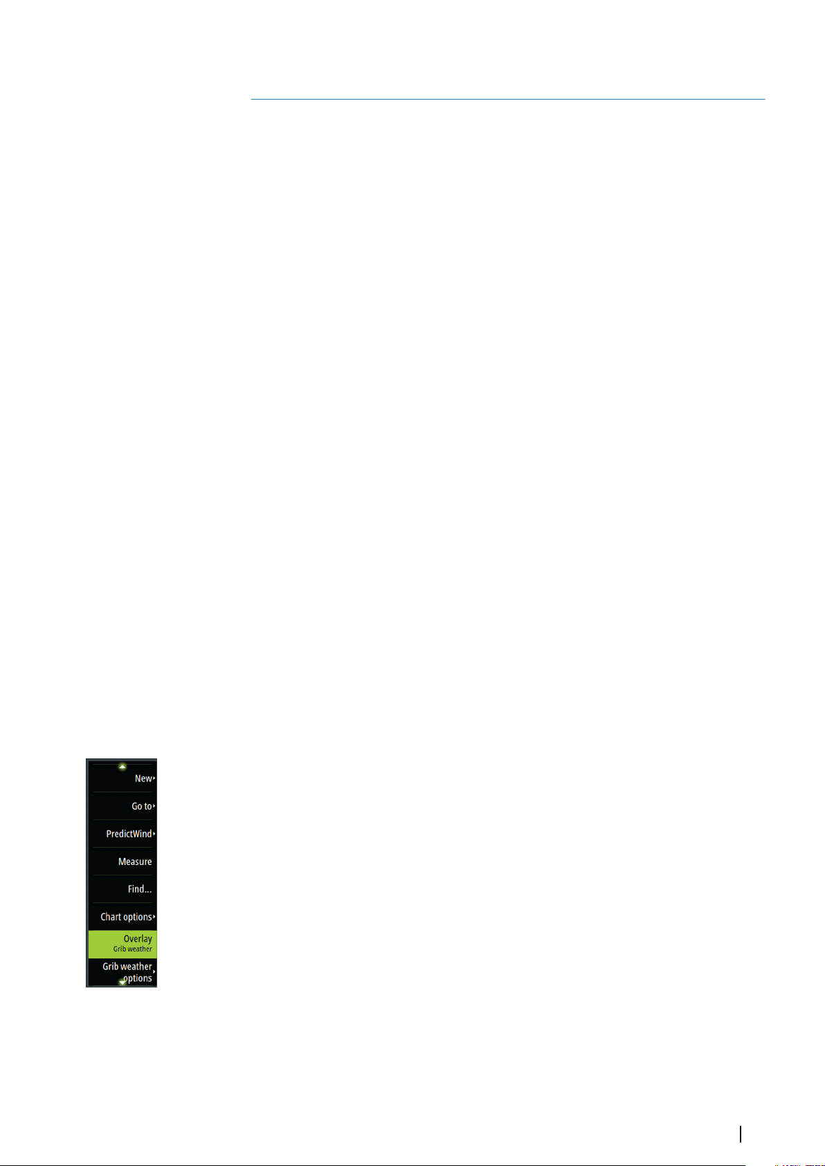
PredictWind
PredictWind weather and PredictWind routes can be displayed on charts.
10
PredictWind weather
PredictWind weather can be displayed as GRIB weather overlay on the chart. To use this
functionality, the appropriate PredictWind subscription is required. Refer to
www.predictwind.com.
Only one weather file can be displayed on the chart at a time.
The PredictWind GRIB weather file can be made available for display as overlay on the chart
the following ways:
• Download PredictWind files automatically or manually from the PredictWind web site
using the unit's internet connection as follows:
Turn on GRIB weather overlay from the Chart menu, refer to "Turn on GRIB weather overlay" on
page 59
- Enter your PredictWind login credentials in the unit, refer to "PredictWind login credentials" on
page 59
- If you want the system to automatically download the files from PredictWind, specify
automatic download High resolution, Offshore (lower resolution), or both. Refer to
"Automatically download PredictWind weather files" on page 60.
- If you want to manually download the files from PredictWind, use the Download
forecast option in the Chart menu. Refer to "Manually download PredictWind weather files" on
page 60.
- Import the file into memory to overlay it on the chart, refer to "Specify PredictWind GRIB overlay
file" on page 62
• Download PredictWind files to a portable storage device connected to a PC and then
import a file from the storage device into the unit's memory as follows:
- Download PredictWind weather files to a portable storage device connected to a PC
Note: Do not use a map memory card. Downloading files to a map card can corrupt
the map card.
- Connect the storage device to the unit
- Turn on GRIB weather overlay from the Chart menu, refer to "Turn on GRIB weather overlay" on
page 59
- Import the file into memory to overlay it on the chart. You can import a weather file
directly from the storage device or from any directory available to the File manager.
Refer to Specify PredictWind GRIB overlay file "Specify PredictWind GRIB overlay file" on page
62.
Turn on GRIB weather overlay
To view GRIB weather overlay on the chart and expand the chart menu to display GRIB
weather menu options, turn on the GRIB weather overlay feature from the chart menu.
PredictWind login credentials
To automatically or manually download weather files from the PredictWind web site, enter
your PredictWind login credentials in the PredictWind GRIB weather dialog.
Access the PredictWind GRIB weather dialog from the Chart settings dialog.
Select Email and enter your PredictWind login email address.
Select Password and enter your PredictWind password.
PredictWind| Zeus³S Operation Manual
59
Page 60
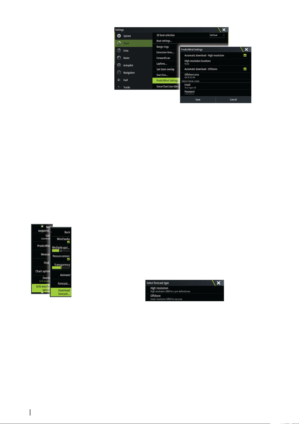
Automatically download PredictWind weather files
The automatic download feature allows your system to regularly check for weather updates
and download the latest data.
Specify if you want to automatically download High resolution (refer to "High resolution" on page
60) or Offshore - lower resolution (refer to "Offshore area (lower resolution)" on page 61) or both
types of GRIB data.
Note: High Resolution downloads require a PredictWind Professional subscription.
Ú
Note: To download data from PredictWind, the unit must have an internet connection
Ú
and your PredictWind login credentials must be entered in the system (refer to "PredictWind
login credentials" on page 59). When an internet connection is made the system will
automatically login to PredictWind with your credentials and start downloading weather
data as specified in the PredictWind GRIB Weather dialog.
Manually download PredictWind weather files
To download a PredictWind weather file manually, select the Download forecast option in
the Chart menu to display the Select forecast type dialog. Use the Select forecast type dialog
to specify the type and area.
Note: To manually download data from PredictWind, the unit must have an internet
Ú
connection. The Download forecast option is only available if you have turned on GRIB
weather overlay on the Chart menu (refer to "Turn on GRIB weather overlay" on page 59), and
your PredictWind login credentials are entered in the system (refer to "PredictWind login
credentials" on page 59).
60
When the GRIB download is complete, the MFD will display a message to show the task is
complete. To view the downloaded GRIB file on the chart, select the downloaded file from
the Forecast menu option. Refer to "Specify PredictWind GRIB overlay file" on page 62.
High resolution
Download location areas are displayed on the chart. Select or deselect single or multiple
locations. The selected areas are highlighted. You can add and remove locations by selecting
Automatic download locations later.
PredictWind| Zeus³S Operation Manual
Page 61
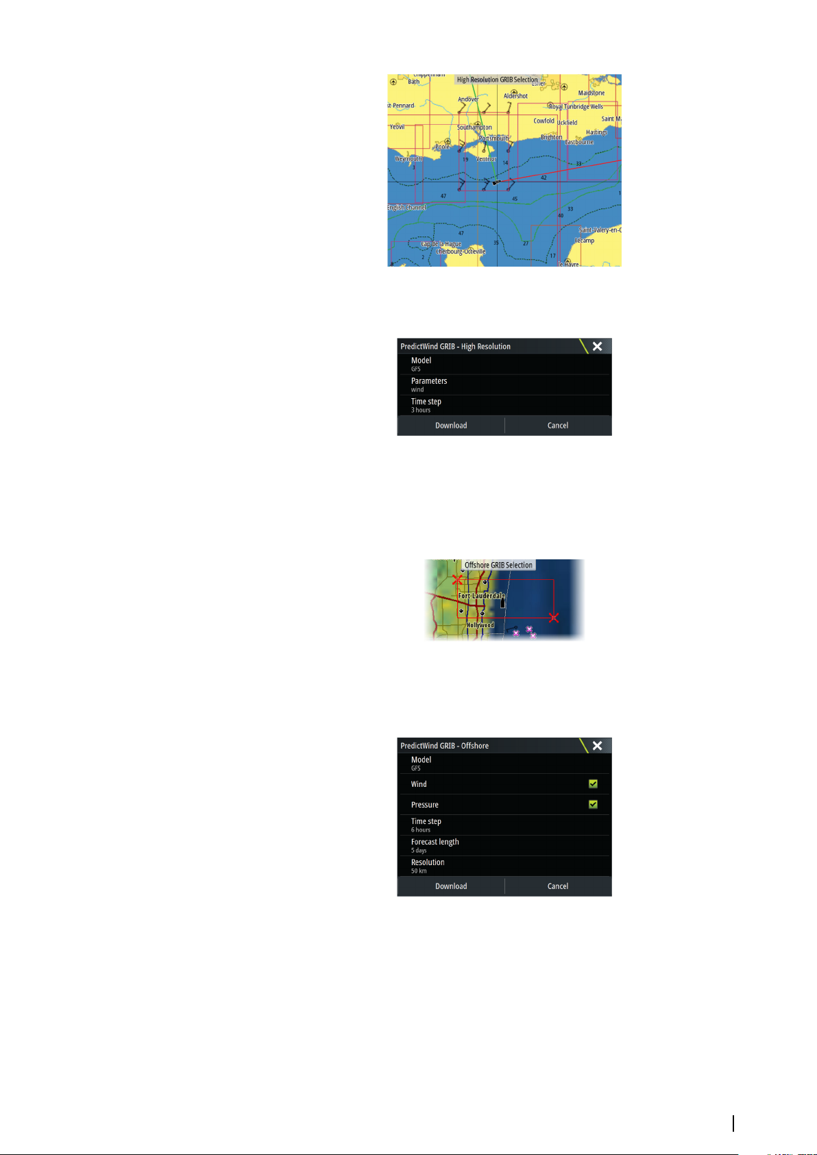
Specify the settings for the high resolution GRIB download, refer to "PredictWind download settings"
on page 61.
Offshore area (lower resolution)
The chart is displayed when you select the offshore area (lower resolution) option with an
expandable rectangle. Drag the rectangle’s corner markers to create the area rectangle you
want to download GRIB weather for.
After you create your offshore area rectangle, choose the select option.
Specify the settings for the offshore (lower resolution) GRIB download, refer to "PredictWind
download settings" on page 61.
PredictWind download settings
Model
Allows you to select from the GRIB model options:
• PWE (PredictWind Forecast) - PredictWind forecast based on the weather observation
from the European Centre for Medium-Range Weather Forecast.
• GFS (Global Forecast System) - a weather observation file from the National Oceanic and
Atmospheric Administration (NOAA) of the USA Department of Commerce.
PredictWind| Zeus³S Operation Manual
61
Page 62
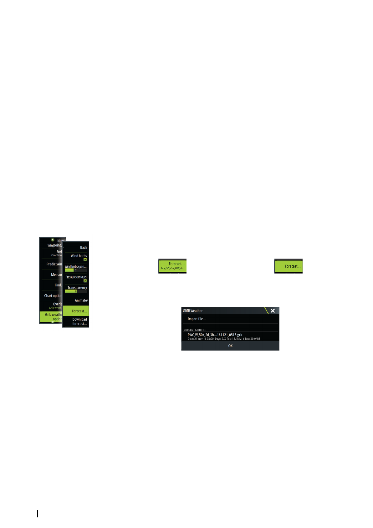
• CMCF (Canadian Meteorological Centre Forecast) – PredictWind forecast based on the
weather observation from the Canadian Meteorological Centre. Available for Offshore
GRIB only.
• GFSF (Global Forecast System Forecast) - PredictWind forecast based on the weather
observation from the National Oceanic and Atmospheric Administration (NOAA) of the
USA Department of Commerce. Available for Offshore GRIB only.
Wind and Pressure
When downloading Offshore GRIB only, you can select Wind and/or Pressure data.
When downloading High Resolutions files, the options are WIND or ALL. Specifying ALL will
download wind and pressure data.
Time step
The size of the time step in the downloaded forecast. For example, a 3 hour time step could
provide weather data for 1200, 1500, 1800 etc., where a 6 hour time step could only provide
1200, 1800 etc. Smaller steps require larger downloads.
Forecast length
The period of the forecast in days.
Resolution
GRIB resolution, select 50 or 100 kilometers between forecast points. Available for Offshore
GRIB only.
Specify PredictWind GRIB overlay file
The Forecast menu option shows the GRIB file which is currently displayed on the chart. If no
file is displayed on the chart, then the menu option does not show a GRIB file.
GRIB file displayed on the chart No GRIB file displayed on the chart
Select the Forecast menu option to open the GRIB Weather dialog.
The GRIB Weather dialog shows which GRIB file is currently displayed as overlay on the chart
and which files are available for display.
Available GRIB files are files downloaded manually or automatically from PredictWind to the
Gribs directory. If you copy GRIB files from a storage device to the Gribs directory using the
file manager, they will be listed as available GRIB files.
Select an available GRIB file to import it into memory and display it as overlay on the chart.
Select the Import file option to import a GRIB file into memory from the storage device or any
directory available to the File manager.
62
Note: GRIB data that is imported overwrites the GRIB data in memory.
Ú
Expired GRIB files
The system identifies GRIB files that have expired and moves them from the available GRIB
files list to the expired GRIB files list. Expired files are files where the time of the final forecast
has passed. Select the Delete expired GRIB files option to delete these expired files from the
system.
PredictWind| Zeus³S Operation Manual
Page 63
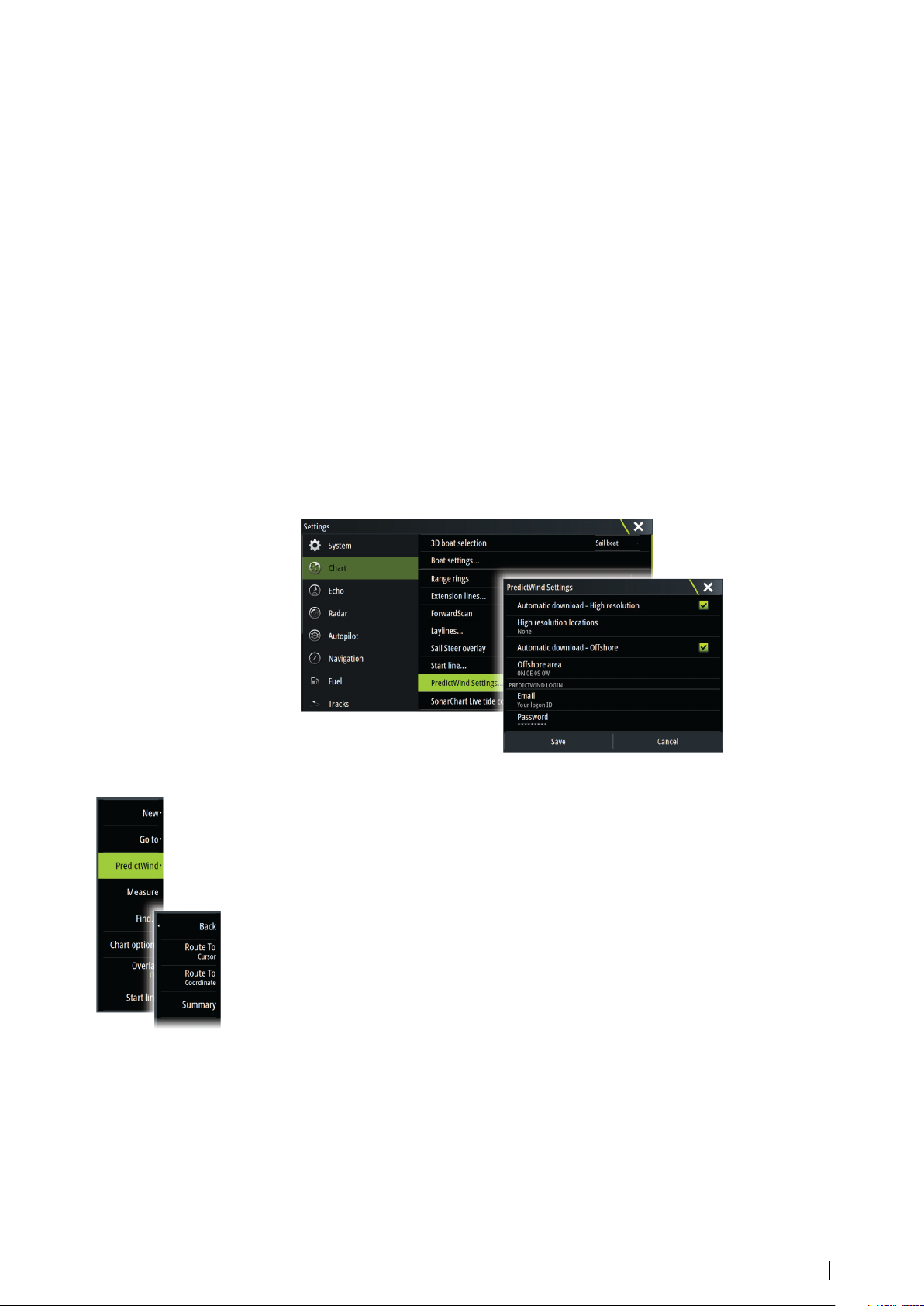
PredictWind weather routing and departure planner
PredictWind Weather routing is an online weather routing service for creating the fastest or
safest route for your trip based on weather conditions.
The departure planner is an online service that advises the best day to depart on a coastal or
offshore trip. It summarizes the wind conditions you will encounter the next 4 days of
departure.
PredictWind routing can also provide a weather forecast for your destination. This
information is available in the Summary panel.
Requirements
• Internet connection – the unit must have an internet connection
• Appropriate PredictWind subscription/account, refer to www.predictwind.com.
• PredictWind login credentials entered in the PredictWind settings dialog.
• Your boat performance details are entered in the polar table at www.predictwind.com.
Polars define the performance of your boat in different wind and wave conditions. It is
important to define this accurately, so the optimal route is as accurate as possible.
Set up and usage
1. Connect your unit to the internet. Refer to "Internet connection" on page 114.
2. Enter your PredictWind credentials in the PredictWind settings dialog.
3. Launch the PredictWind routing feature, the following options are available:
• Route to cursor
a. Activate the cursor on the chart.
b. Select the PredictWind menu option.
c. Select the route to cursor menu option to specify route to cursor information. For
specifying details refer to "PredictWind Routing dialog options" on page 64.
d. Select Download to request a new route from PredictWind.
• Route to coordinate
a. Select the PredictWind menu option.
b. Select the route to coordinate menu option to display the PredictWind Routing
dialog.
c. Select the destination option to set the destination coordinate and select OK. The
PredictWind Routing dialog opens showing the destination coordinate you
specified.
d. Select options in the PredictWind Routing dialog to specify route to coordinate
information. For specifying details refer to "PredictWind Routing dialog options" on page
64.
e. Select Download to request a new route from PredictWind.
PredictWind| Zeus³S Operation Manual
63
Page 64
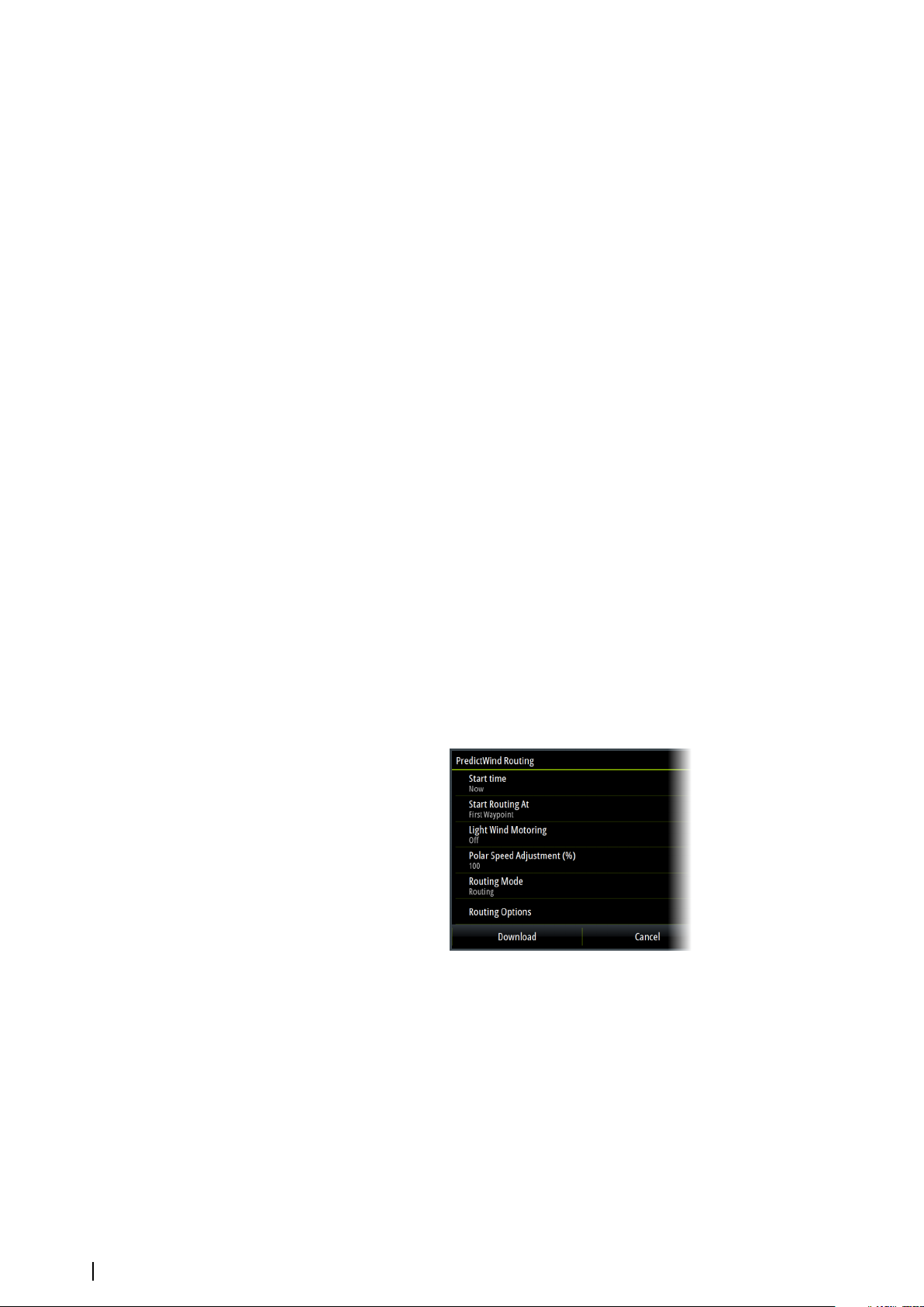
• Route to waypoint
a. Do one of the following:
• Use the Find menu option, select Waypoints and then select the waypoint in the
list to open the Edit Waypoint dialog.
• Select the waypoints button in the toolbar and select the waypoint in the list to
open the Edit Waypoint dialog.
• Select the waypoint on the chart. This lists the selected waypoint in the menu.
Select the waypoint in the menu and then Details in the expanded menu to
open the Edit Waypoint dialog.
b. Select PredictWind to specify route to waypoint information. For specifying details
refer to "PredictWind Routing dialog options" on page 64.
c. Select Download to request a new route from PredictWind.
• Use existing route
a. Do one of the following:
• Use the Find menu option and select the route in the list to open the Edit Route
dialog.
• Select the waypoints button in the toolbar and select the route in the list to
open the Edit Route dialog.
• Select the route on the chart. This lists the selected route in the menu. Select the
route in the menu and then Details in the expanded menu to open the Edit
Route dialog.
b. Select PredictWind to specify routing information. For specifying details refer to
"PredictWind Routing dialog options" on page 64.
c. Select Download to request a new route from PredictWind.
If there is an internet connection and proper account credentials entered in the PredictWind
settings dialog, a route will be downloaded from PredictWind.
PredictWind Routing dialog options
Start Time
Specify the start date and time. If Now is selected, the date and time options are disabled.
64
Start Routing At
Specify to PredictWind if you want weather routing to start from the current vessel position
or to start weather routing at the first waypoint in the route.
Light Wind Motoring
Specify light wind motoring options:
• Motoring speed
• The wind speed at which you would stop sailing and start motoring
PredictWind| Zeus³S Operation Manual
Page 65
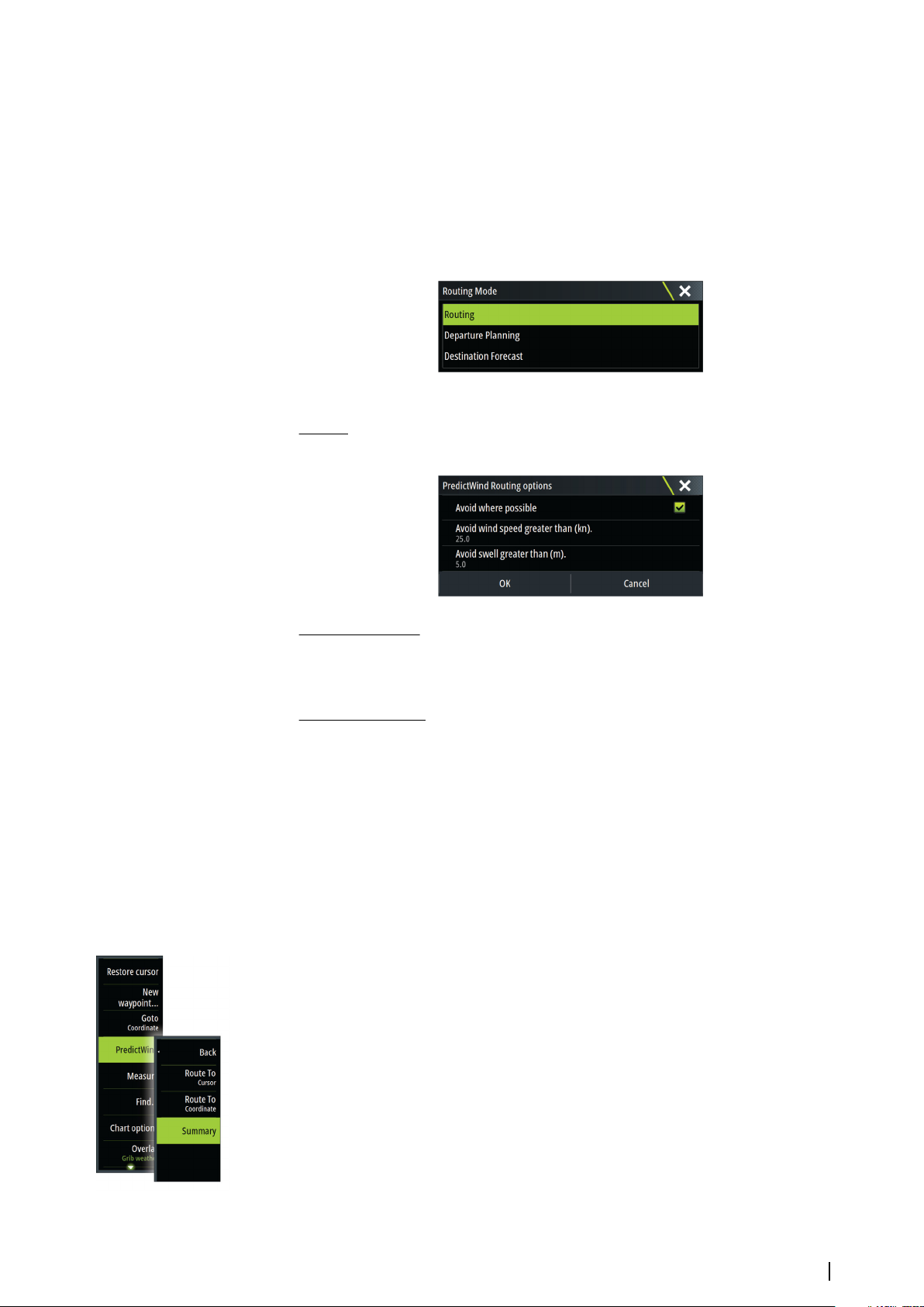
Polar Speed Adjustment
Adjust the polar speed by a percentage. If, for example, you are delivering a boat short
handed and expect the boat performance to be slower than your Polar by 20%, apply 80% to
the Polar Speed Adjustment.
Note: The polar must be selected in your PredictWind Account settings that you access
Ú
online (at PredictWind.com).
Routing Mode
You can select one of the following modes:
• Routing - Opens the PredictWind Routing dialog with Routing Options enabled. Select
Routing Options to specify the wind speeds and swells you want to avoid on the route.
• Departure Planning - Opens the PredictWind Routing dialog with Departure Options
enabled. Select Departure Options to specify the time you want to space the departures (1
hour, 3 hours, 6 hours, 12 hours or 24 hours) and the forecast model (GFS/ECMWF or PWE/
PWG) you want PredictWind to use.
• Destination Forecast - Select this option to request destination forecast information from
PredictWind.
Routing and destination forecast details are provided in the Summary panel.
Download Management
To view the status of any ongoing route downloads select the Files icon on the Tool panel
and then Transfers to see transfer status. When a download completes, the route is drawn on
the chart. Old routes are deleted when the new route becomes available. If a route is being
followed when a new one is downloaded it will continue to be followed until navigation is
finished.
PredictWind routing summary
Select the Summary option in the PredictWind menu to view detailed routing information.
PredictWind| Zeus³S Operation Manual
65
Page 66
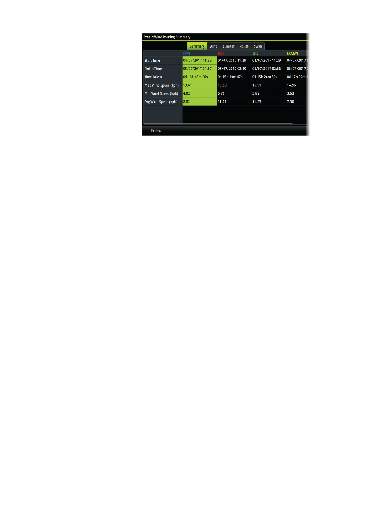
Additional summary information is available for wind, current, route, and swell.
Select Follow to sail the route.
66
PredictWind| Zeus³S Operation Manual
Page 67
Autopilot
11
Safe operation with the autopilot
Warning: An autopilot is a useful navigational aid, but DOES NOT replace
a human navigator.
Warning: Ensure the autopilot has been installed correctly, commissioned
and calibrated before use.
Note: For safety reasons a physical standby key should be available.
Ú
Note: The WheelKey can be configured to be a standby key. Refer to "Configurable WheelKey"
Ú
on page 18.
Do not use automatic steering when:
• In heavy traffic areas or in narrow waters
• In poor visibility or extreme sea conditions
• When in areas where use of an autopilot is prohibited by law
When using an autopilot:
• Do not leave the helm unattended
• Do not place any magnetic material or equipment near the heading sensor used by the
autopilot system
• Verify at regular intervals the course and position of the vessel
• Always switch the autopilot to standby and reduce speed in due time to avoid hazardous
situations
Autopilot alarms
For safety reasons it is recommended to turn on all autopilot alarms when operating the
autopilot.
For more information, refer to "Alarms" on page 126.
Selecting active autopilot
If 2 autopilot computers are configured for MFD control, only one of them can be active at a
time. We recommend you only power up one at a time.
The Autopilot controller
The Autopilot controller has a fixed position on the left-side of the page.
The following Autopilot controller options are available:
• Autopilot controller, showing active mode, heading, rudder and various steering
information depending on active autopilot mode. Manual adjustments to the set
heading/course can only be made when the port and starboard arrow indicators are
illuminated red and green.
• Mode selection, includes access to tack or gybe options.
• Tack or Gybe selection, available when in Heading hold or Wind mode and boat type is set
to Sail in the autopilot commissioning dialog.
Autopilot| Zeus³S Operation Manual
67
Page 68
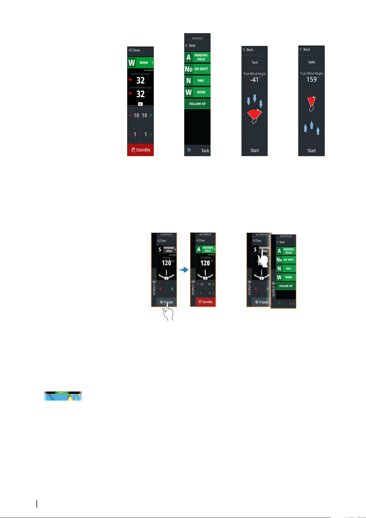
Autopilot controller Mode selection Start tack Start gybe
Engaging and disengaging the autopilot
To engage the autopilot:
• Select the engage button to activate last active mode
• Select the mode button to display the list of available modes, then select the preferred
mode
The autopilot will engage in the selected mode, and the autopilot controller will change to
show active mode options.
To disengage the autopilot:
• Select the standby button
68
When the autopilot is in standby, the boat must be steered manually.
Autopilot indication
The status bar shows autopilot information as long as an autopilot computer is connected.
Autopilot modes
The autopilot has several steering modes. The number of modes and features within the
mode depend on the autopilot computer, the boat type and available inputs.
Non-Follow Up mode (NFU)
In this mode the port and starboard buttons are used to control the rudder.
Activate this mode by selecting the port or starboard button when the autopilot is in
standby.
Autopilot| Zeus³S Operation Manual
Page 69
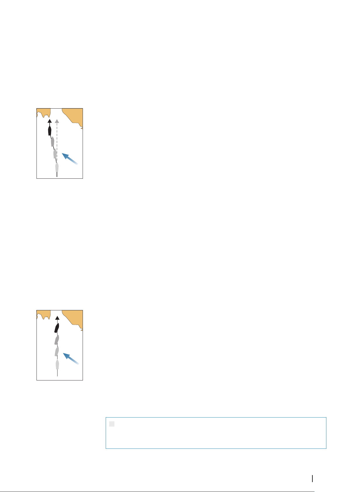
Follow-Up mode (FU)
W
W
In this mode the rudder moves to a set rudder angle. The rudder position is maintained at
the set angle.
To change the set rudder angle
• Select the port or starboard button
• With the autopilot controller active, turn the rotary knob
Heading hold mode (A)
In this mode the autopilot steers the vessel on the set heading.
When the mode is activated, the autopilot selects the current compass heading as the set
heading.
Note: In this mode the autopilot does not compensate for any drifting caused by current
Ú
and/or wind (W).
To change the set heading
• Select a port or starboard button
• With the autopilot controller active, turn the rotary knob
An immediate heading change takes place. The heading is maintained until a new heading is
set.
Tacking in Heading hold mode
Note: Only available when the boat type is set to sail (autopilot configuration).
Ú
Note: Tacking should only be performed into the wind and must be tried out in calm sea
Ú
conditions with light wind to find out how it works on your vessel.
Tacking in heading hold mode changes the heading by a fixed tack angle, either to port or
starboard.
The rate of turn during the tack/gybe is set by the tack time in the autopilot settings dialog.
Refer to "Autopilot settings" on page 71.
To initiate a tack:
• Selecting the tack button in the mode list, then selecting the tack direction.
NoDrift mode
In NoDrift mode the vessel is steered along a calculated track line, from present position and
in a direction set by the user.
When the mode is activated, the autopilot will draw an invisible track line based on current
heading from the vessel’s position. The autopilot will now use the position information to
calculate the cross track distance, and automatically steer along the calculated track.
Note: If the vessel is drifting away from the track line due to current and/or wind (W), the
Ú
vessel will follow the line with a crab angle.
To change the set track line
• Select a port or starboard button
• With the autopilot controller active, turn the rotary knob
NAV mode
Warning: NAV mode should only be used in open waters. Navigation
mode must not be used while sailing, as course changes may result in
unexpected tacks or gybes.
Prior to entering NAV mode you must be navigating a route or towards a waypoint.
Autopilot| Zeus³S Operation Manual
69
Page 70
In NAV mode the autopilot automatically steers the vessel to a specific waypoint location, or
along a pre-defined route. Position information is used to change the course to steer to keep
the vessel on the track line to the destination waypoint.
Note: For information about navigation, refer to "Navigating" on page 44.
Ú
NAV mode options
While in NAV mode the following buttons are available in the autopilot controller:
Restart
Restarts the navigation from the vessel’s current position.
Skip
Skips the active waypoint and steers towards the next waypoint. This option is only available
when navigating a route with more than one waypoint between the vessel position and the
end of the route.
Cancel
Cancels active navigation and deselects the current route or waypoint navigation. The
autopilot is switched to heading hold mode, steering the vessel on the heading that was
active when the cancel button was selected.
Note: This is different from selecting standby which does not stop current navigation.
Ú
Turning in NAV mode
When the vessel reaches a waypoint, the autopilot will give an audible warning and display a
dialog with the new course information.
There is a limit for the allowed automatic course change to next waypoint in a route:
• If the required course change to the next waypoint is less than the course change limit,
the autopilot will automatically change the course
• If the required course change to next waypoint is more than the set limit, you are
prompted to verify that the upcoming course change is acceptable. If the turn is not
accepted, the vessel will continue with the current set heading.
The course change limit setting depends on the autopilot computer. Refer to the autopilot
computer documentation.
Wind mode
Note: Wind mode is only available when the boat type is set to Sail. It is not possible to
Ú
activate wind mode if wind information is missing.
In wind mode the autopilot captures the current wind angle as steering reference, and
adjusts the heading of the boat to maintain this wind angle.
The autopilot will keep the boat on the set wind angle until a new wind angle is set.
Warning: In wind mode the autopilot steers to the apparent or true wind
angle and not to a compass heading. Any wind shift could result in the
vessel steering on an undesired course.
70
To change the set wind reference angle
• Select a port or starboard button
• With the autopilot controller active, turn the rotary knob
An immediate change of wind reference angle takes place.
Tacking and gybing in wind mode
The tack/gybe option in wind mode mirrors the set wind angle on the opposite tack.
Autopilot| Zeus³S Operation Manual
Page 71
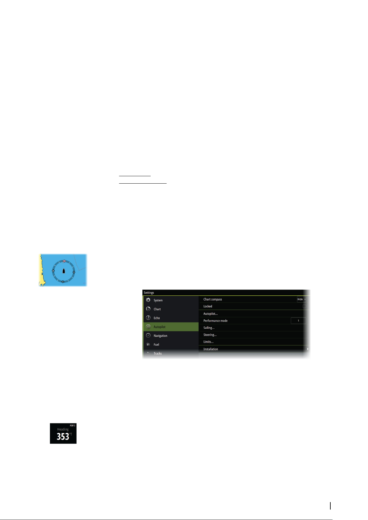
Tacking and gybing in wind mode can be performed when sailing with apparent or true
wind as the reference. In either case the true wind angle must be less than 90° (tacking) and
more than 120° (gybing).
The rate of turn during the tack/gybe is set by the tack time in the autopilot settings dialog.
Refer to "Autopilot settings" on page 71.
To initiate a tack or gybe:
• Select the Tack/Gybe option in the mode list
Note: The autopilot will temporarily add a 5° bear-away on the new tack to allow the
Ú
boat to pick up speed. After a short period the wind angle will return to the set angle.
Autopilot settings
The Autopilot settings dialog depends on which autopilot computer that is connected to the
system. If more than one autopilot is connected, the Autopilot settings dialog shows option
for the active autopilot.
The autopilot settings can be split between settings done by the user, and settings done
during installation and commissioning of the autopilot system.
User settings can be changed for various operational conditions or user preferences.
•
• Installation settings are defined during commissioning of the autopilot system. No
changes should later be done to these settings.
The following sections describe the user settings per autopilot computer. For installation
settings, refer to the installation manual.
Common user settings
The following user settings are common to all autopilots.
Chart compass
Select to display a compass symbol around your boat on the chart panel. The compass
symbol is off when the cursor is active on the panel.
H5000 Specific user settings
Performance
The Performance controls the response of the autopilot steering. There are five levels of
performance modes:
• Level one consumes the least amount of power when steering the autopilot and offers
the slowest response
• Level five consumes the most power and has the highest response
The performance mode is indicated in the top right corner of the status display in the
Autopilot controller.
Autopilot| Zeus³S Operation Manual
71
Page 72
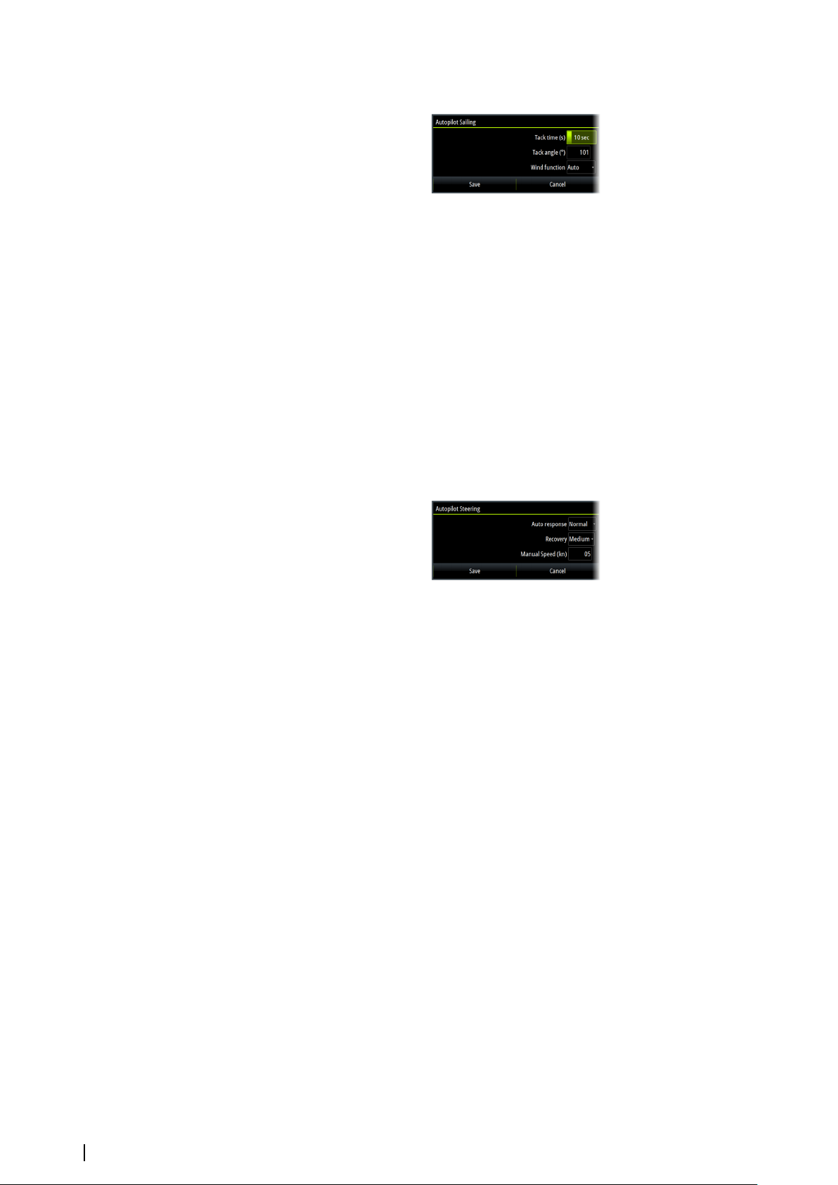
Sailing
This option allows for manually changing parameters that were set during the
commissioning of the autopilot computer. For more details of the settings, refer to the
separate documentation for the autopilot computer.
• Tack time: Controls the rate of turn (tack time) when performing a tack in Heading hold
and Wind mode.
• Tack angle: Controls the angle that the boat will tack to between 50º - 150º in Heading
hold mode
• Wind function: Select what wind function the autopilot will use when in wind mode
Auto:
If TWA is <70º: Wind mode will use AWA
If TWA is ≥70º: Wind mode will use TWA
- Apparent
- True
Steering
This option allows for manually changing parameters that were set during the
commissioning of the autopilot computer. For more details of the settings, refer to the
separate documentation for the autopilot computer.
• Auto response: controls the rate that which the autopilot reacts to any environmental
influences on the vessels desired course
Off: The autopilot will always remain in the response mode selected
-
- Economy: The autopilot will need to sense large environmental changes before
increasing the response setting
- Normal: The autopilot will need to sense moderate environmental changes before
increasing the response settings
- Sport: The autopilot will be most sensitive to changing conditions and will
automatically increase its response rate to counter environmental changes
• Recovery: Allows the user to set the sensitivity to course errors and how the autopilot will
react to unexpected events, for example sudden wave or wind shifts. This function allows
the autopilot to instantaneously increase the steering response to its maximum setting
(Perf 5), and make a rapid recovery. The Recovery will automatically switch off after 15
seconds or when the heading error has been corrected. The autopilot will then resume
the previous response setting and continue normal operation.
- Off
- Narrow: The autopilot is most sensitive to sudden course changes corrected
- Medium: The autopilot is configured to the medium value when correcting sudden
course changes
- Wide: The autopilot is least sensitive to sudden course changes
72
• Manual speed: If neither boat speed or SOG data is available and or deemed reliable a
manual value for speed source can be entered and used by the autopilot to aid steering
calculations
Autopilot| Zeus³S Operation Manual
Page 73
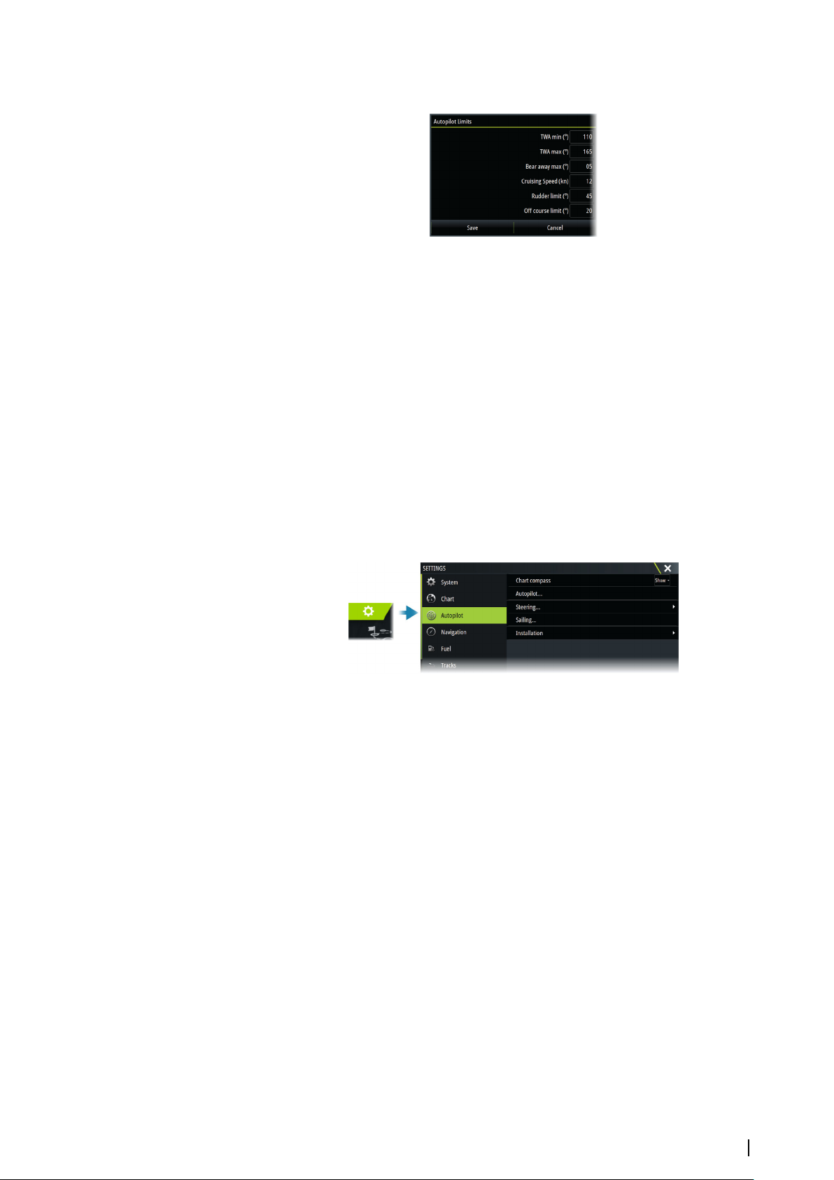
Limits
This option allows for manually changing parameters that were set during the
commissioning of the autopilot computer. For more details of the settings, refer to the
separate documentation for the autopilot computer.
Allows control of the True Wind Angle range where Gust and True Wind Speed response can
be configured and controlled.
• TWA min: Minimum True Wind Angle that gust and True Wind Speed response operate in.
• TWA max: Maximum True Wind Angle that gust and True Wind Speed response operate
in.
• Bear away max: Maximum angle the vessel will bear away during stability control
• Cruising speed: The preferred cruising speed for this vessel (comfortable and economical)
• Rudder limit: Determines the maximum rudder movement in degrees from midship
position that the autopilot can command the rudder in the automatic modes. The Rudder
limit setting is only active during autosteering on straight courses, NOT during course
changes. Rudder limit does not affect Non-Follow-up steering.
• Off course limit: Defines the limit for the off course alarm
NAC-2/NAC-3 specific user settings
Autopilot
Switches the view to the last active page.
Steering
These options allow for manually changing low speed and high speed parameters that were
set during the commissioning of the autopilot computer. For more details, refer to the
separate documentation for the autopilot computer.
Selecting the low speed option or the high speed option opens dialogs the following
parameters can be changed.
• Turn rate: Preferred turn rate used while turning in degrees per minute.
• Rudder gain: This parameter determines the ratio between commanded rudder and the
heading error. The higher rudder value the more rudder is applied. If the value is too small
it will take a long time to compensate for a heading error, and the autopilot will fail to
keep a steady course. If the value is set too high the overshoot will increase and the
steering will be unstable.
• Counter rudder: Relation between change in heading error and applied rudder. Higher
counter rudder will reduce applied rudder faster when approaching the set heading.
• Auto trim: Controls how aggressively the autopilot will apply rudder to compensate for a
constant heading offset, e.g. when external forces such as wind or current affects the
heading. Lower auto trim will give faster, limitation of a constant heading offset.
• Init rudder: Defines how the system moves the rudder when switching from manual
steering to an automatic mode.
Autopilot| Zeus³S Operation Manual
73
Page 74

- Rudder limit: Determines the maximum rudder movement in degrees from midship
position that the autopilot can command the rudder in the automatic modes. The
Rudder limit setting is only active during autosteering on straight courses, not during
course changes. Rudder limit does not affect Follow-up or Non-Follow-up steering.
Off heading limit: Sets the limit for the off heading alarm. An alarm occurs when the
actual heading deviates from the set heading more than the selected limit.
• Rudder limit: Determines the maximum rudder movement in degrees from midship
position that the autopilot can command the rudder in the automatic modes. The Rudder
limit setting is only active during autosteering on straight courses, not during course
changes. Rudder limit does not affect Follow-up or Non-Follow-up steering.
• Off heading limit: Sets the limit for the off heading alarm. An alarm occurs when the actual
heading deviates from the set heading more than the selected limit.
• Track response: Defines how fast the autopilot shall respond after having registered a
cross track distance.
• Track approach angle: Defines the angle used when the vessel is approaching a leg. This
setting is used both when you start navigating and when you use track offset.
• Course change confirm angle: Defines the limits for course change to next waypoint in a
route. If the course change is more than this set limit, you are prompted to verify that the
upcoming course change is acceptable.
Sailing
Note: Sailing parameters are only available when the boat type is set to Sail.
Ú
This option allows for manually changing parameters that were set during the
commissioning of the autopilot computer. For more details of the settings, refer to the
separate documentation for the autopilot computer.
• Tack time: Controls the rate of turn (tack time) when performing a tack in wind mode.
• Tack angle: Controls the angle that the boat will tack to between 50º - 150º in Heading
hold mode.
• Wind function: Select what wind function the autopilot will use when in wind mode.
-
Auto:
If TWA is <70º, Wind mode will use AWA.
If TWA is ≥70º, Wind mode will use TWA.
- Apparent
- True
• Manual speed: If neither boat speed or SOG data is available and or deemed reliable a
manual value for speed source can be entered and used by the autopilot to aid steering
calculations.
74
Autopilot| Zeus³S Operation Manual
Page 75
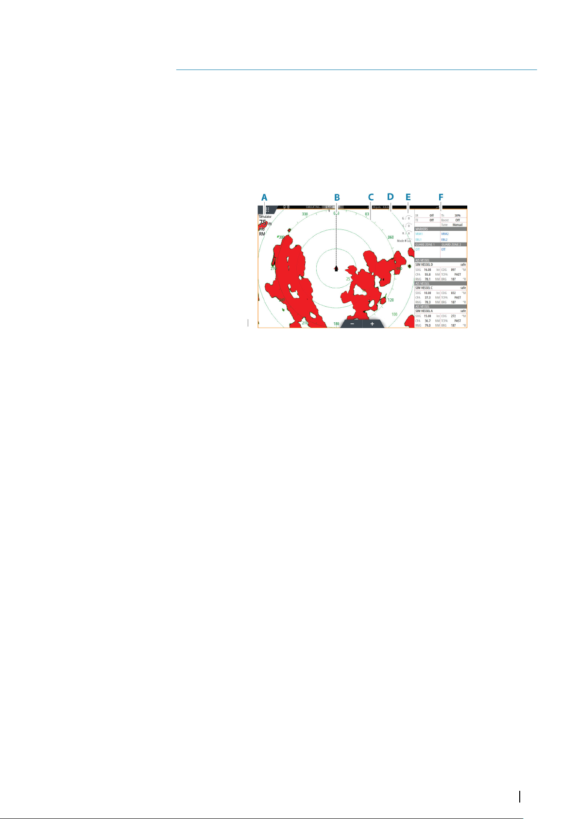
Radar
12
About radar
Several radar sensors are supported.
This chapter describes features and options for a variety of supported radars. The features
and options available to you are dependent on the radar antenna(s) connected to your
system.
The Radar panel
A Radar information window
B Heading line*
C Compass*
D Range rings *
E Quick image controls
F Data bar**
* Optional radar symbology. Radar symbology can be turned ON/OFF collectively from the
radar menu, or individually as described in radar settings dialog.
** You can show or hide the data bar using the data bar option in the radar settings dialog.
Dual radar
You can connect to any combination of two supported radars and see both radar images at
the same time.
Note: Interference will be seen on the Broadband Radar on most ranges when a pulse or
Ú
Halo radar, and a Broadband radar are transmitting at the same time on the same boat.
We recommend to only transmit on one radar at a time. For example, transmit
Broadband radar for typical navigational usage, or pulse or Halo radar to locate weather
cells, defined coastlines at a distance and to trigger Racons.
You can select a dual radar panel by pressing and holding the Radar application button on
the home page, or by creating a favorite page with two radar panels.
Selecting the radar source
You specify the radar in the Radar panel by selecting one of the available radars in the radar
source menu option. If you have a multiple Radar panel, the radar is set individually for each
radar panel. Activate one of the radar panels, and then select one of the available radars in
the radar source menu option. Repeat the process for the second radar panel, and select an
alternative radar for this panel.
Note: The 3-digit radar source number is the last 3 digits of the radar's serial number.
Ú
Radar| Zeus³S Operation Manual
75
Page 76

Radar overlay
You can overlay the Radar image on the Chart. This can help you to easily interpret the radar
image by correlating the radar targets with charted objects.
Note: A heading sensor must be present in the system for radar overlay.
Ú
When the radar overlay is selected, basic radar operational functions are available from the
Chart panel’s menu.
Selecting radar overlay source on chart panels
To select the radar source of the radar overlay displayed on the chart panel, use the Radar
options and then Source chart panel menu options to select the radar source.
For chart pages with more than one chart with radar overlay, it is possible to set up different
radars sources for each chart panel. Activate one of the chart panels and then select one of
the available radars in the radar source menu option. Repeat the process for the second chart
panel with radar overlay, and select an alternative radar for this panel.
Radar operational modes
The radar’s operational modes are controlled from the Radar menu. The following modes are
available:
Power off
The power to the radar scanner is turned off. Power off is only available when radar is in
standby mode.
Standby
The power to the radar scanner is on, but the radar is not transmitting.
Note: You can also put the radar in standby mode from the System Controls dialog.
Ú
Transmit
The scanner is on and transmitting. Detected targets are drawn on the radar PPI (Plan
Position Indicator).
Note: You can also put the radar in transmit mode from the System Controls dialog.
Ú
Radar Range
You adjust radar range by selecting the zoom icons on the radar panel.
Dual range
When connected to a radar with dual range capability, it is possible to run the radar in Dual
Range mode.
The radar appears in the radar sources menu as two virtual radar sources A and B. Range and
radar controls for each virtual radar source are fully independent and the source can be
selected for a particular chart or radar panel in the same manner as dual radar described in
"Selecting the radar source" on page 75.
Note: Some controls that are related to physical properties of the radar itself are not
Ú
independent of source. These are Fast Scan, Antenna Height and Bearing alignment.
76
MARPA is fully independent and up to 10 targets may be tracked for each virtual radar
source.
Up to two independent Guard Zones may also be defined for each virtual radar source.
Radar sector blanking
If your radar has sector blanking capability, you can define up to four sectors on the PPI inside
which no radar data is transmitted. This enables you to blank-out interference caused by
features on your boat or from a secondary radar. The blanking occurs on the main radar
Radar| Zeus³S Operation Manual
Page 77
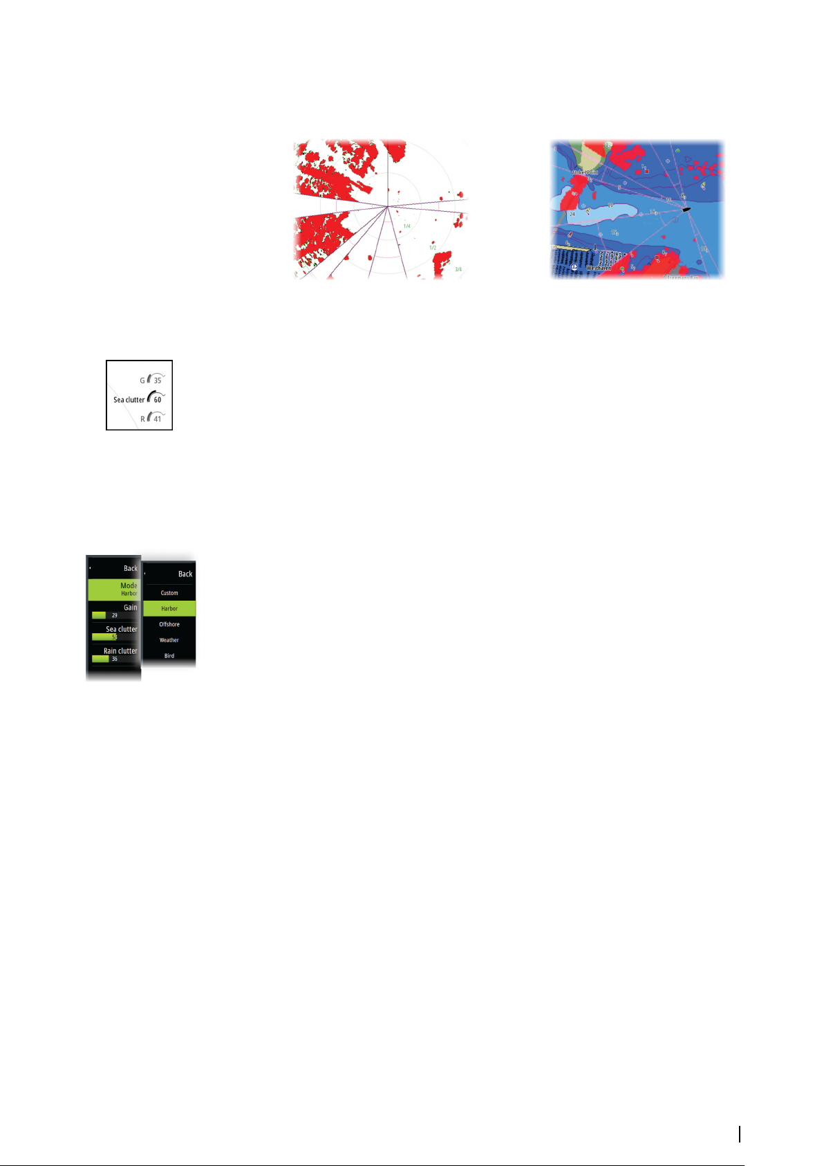
image and radar overlay on a chart. An enabled sector is shown as a magenta outline with 3
arcs crossing the blanking area. To specify radar sector blanking, refer to the unit's installation
manual.
Main radar PPI Radar overlay on a chart
Adjusting the radar image
You may be able to improve the radar image by adjusting the radar sensitivity, and by
filtering out the random echoes from sea and weather conditions.
The radar control images are located in the upper right corner of the radar panel. You can
adjust the image settings by selecting the radar control image or by pressing the rotary knob.
The selected control expands and displays its name in full and a slide bar is displayed. You
can then adjust the value by turning the rotary know or by using the slide bar.
You can also adjust the image settings from the radar menu.
Menu options can vary depending on your radar's capability.
Radar modes
Use modes are available with preset control settings for different environments. Not all
modes are available for all radar transceivers.
Modes in dual ranges
When connected to a radar with dual range capability, it is possible to run the radar in Dual
Range mode.
Modes can be set independently for each range. For example, you can have Offshore mode
for range A and Weather mode for range B. However, interaction between ranges occurs in
some cases:
• When using Bird mode for both ranges, maximum range is restricted to 24 NM and range
resolution is reduced.
• Fast scan - The antenna rotation speed is set to the slower of the two modes selected. For
example, Fast Scan is disabled when using Harbor and Weather modes because Fast Scan
is Off in Weather mode.
• The Interference reject setting can affect the interference seen or removed on both
ranges.
Directional clutter rejection
This mode automatically works when GAIN = AUTO and SEA = HARBOR or OFFSHORE. The
purpose is to allow smaller vessels to be seen in the leeward direction of the sea clutter. The
GAIN of the radar receiver is increased dynamically during the sweep, in the leeward
direction, for increased target sensitivity in heavier sea states.
When GAIN or SEA = MANUAL, the Directional Clutter Rejection mode will be OFF (nondirectional).
In addition, CALM, MODERATE or ROUGH STC Curve settings are available in the Radar
options menu to better optimize the radar image to your liking.
Gain
The gain controls the sensitivity of the radar receiver.
A higher gain makes the radar more sensitive to radar returns, allowing it to display weaker
targets. If the gain is set too high, the image might be cluttered with background noise.
Radar| Zeus³S Operation Manual
77
Page 78
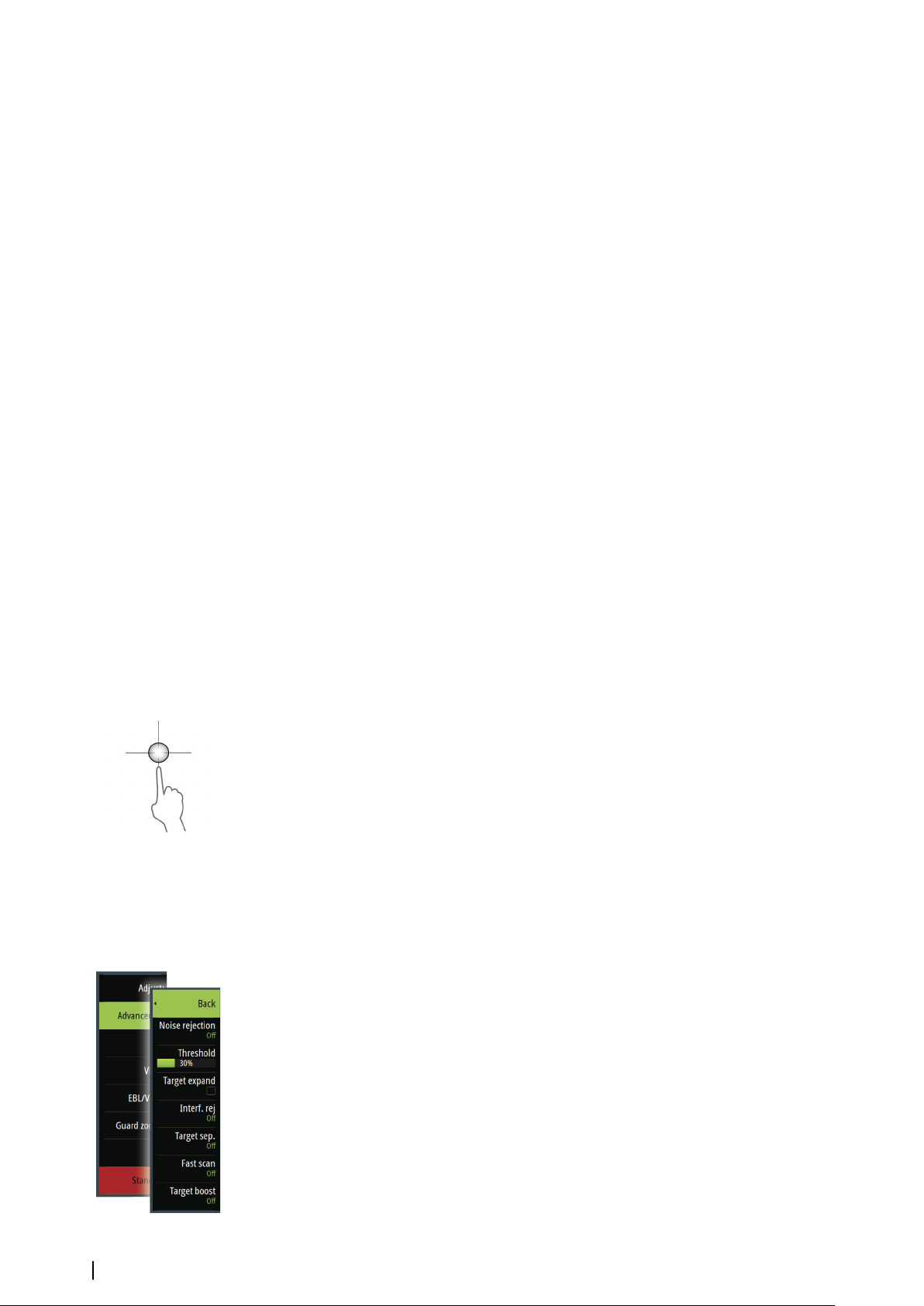
Gain has a manual and an automatic mode. You toggle between automatic and manual
mode in the slide bar, or by pressing and holding the rotary knob.
Sea clutter
Sea clutter is used to filter the effect of random echo returns from waves or rough water near
the vessel.
When you increase Sea clutter, filtering the on-screen clutter caused by the echoes of waves
is reduced.
The system includes predefined Sea clutter settings for harbor and offshore conditions for all
radar systems except Halo, in addition to the manual mode where you can adjust the
settings. For all radar systems except Halo, you select Sea clutter modes from the menu, or by
a long press on the rotary knob. You can only adjust the Sea clutter value in manual mode.
Auto Sea Offset
To allow fine tuning of the Sea control while in Auto mode (Auto uses directional adaptive
clutter rejection), the Auto setting may be offset.
Rain clutter
Rain clutter is used to reduce the effect of rain, snow or other weather conditions on the
radar image.
The value should not be increased too much as this may filter out real targets.
Using the cursor on a radar panel
By default, the cursor is not shown on a radar panel.
When you position the cursor on the radar panel, the cursor position window is activated.
Go to cursor
You can navigate to a selected position on the image by positioning the cursor on the panel,
and then using the go to cursor menu option.
The cursor assist function
Note: The cursor assist function is available if it is enabled. Refer to "Customizing the long press
Ú
feature" on page 18.
The cursor assist function allows for fine tuning and precision placement of the cursor
without covering details with your finger.
Activate the cursor on the panel, then press and hold your finger on the screen to switch the
cursor symbol to a selection circle, appearing above your finger.
Without removing your finger from the screen, drag the selection circle to the desired
position.
When you remove your finger from the screen the cursor reverts to normal cursor operation.
Advanced radar options
Menu options can vary depending on your radar's capability.
78
Noise Rejection
Sets the amount of noise filtering applied by the radar. Target sensitivity is increased at
longer ranges when this control is set to Low or High, but does cause some loss of target
discrimination.
Note: To get maximum range performance from the radar, transmit on one range only,
Ú
set the Noise Reject control to High and the threshold as low as possible. The default is
30% for less clutter on the screen. In some areas where extreme high interference may
exist, try OFF for best radar image.
Radar| Zeus³S Operation Manual
Page 79
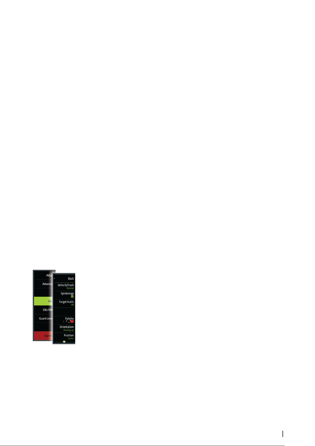
Radar threshold
The threshold sets required signal strength for the lowest radar signals. Radar returns below
this limit are filtered and are not displayed.
Default value: 30%.
Target expansion
Target expansion increases the length of targets in range, making them easier to see.
Rejecting radar interference
Interference could be caused by radar signals from other radar units operating in the same
frequency band.
A high setting reduces the interference from other radars.
In order not to miss weak targets, the interference rejection should be set to low when no
interference exists.
Target separation
Controls the target discrimination of the radar (separation between objects is more
prominent).
Fast scan
Sets the speed of the radar antenna rotation. This option gives faster target updates.
Note: Maximum speed may not be achieved depending on the radar Settings, Mode,
Ú
and Range selected. The radar will only rotate as fast as the current control settings allow.
Sea State
Set the Sea State control according to current sea conditions for best sea clutter rejection.
Target boost
The target boost control increases pulse length or reduces radar bandwidth to make targets
appear larger in range and increase radar sensitivity.
Radar view options
View menu options vary depending on your radar antenna.
VelocityTrack
Note: When VelocityTrack is enabled antenna rotation speed may be reduced.
Ú
Note: When operating the radar in Dual range mode with one of the ranges set to 36
Ú
nm or more, increased VelocityTrack coloring noise over land areas may be seen.
Doppler coloring is a navigation aid to distinguish moving targets approaching or diverging
from your vessel. The radar indicates if a target is approaching or diverging from your vessel
when both these conditions are true:
• The target's relative speed is greater than the VelocityTrack speed threshold.
• The target is not geo-stationary (e.g. land or a marker buoy).
The following options are available:
• Off - turns off Doppler coloring
• Normal - approaching targets and diverging targets are colored.
• Approaching targets - only approaching targets are colored
The color of approaching and diverging targets depends on the palette used:
• Diverging targets are blue colored on all radar image palettes.
• Approaching target colors on radar image palettes:
-
Black/Red palette - Yellow
Radar| Zeus³S Operation Manual
79
Page 80
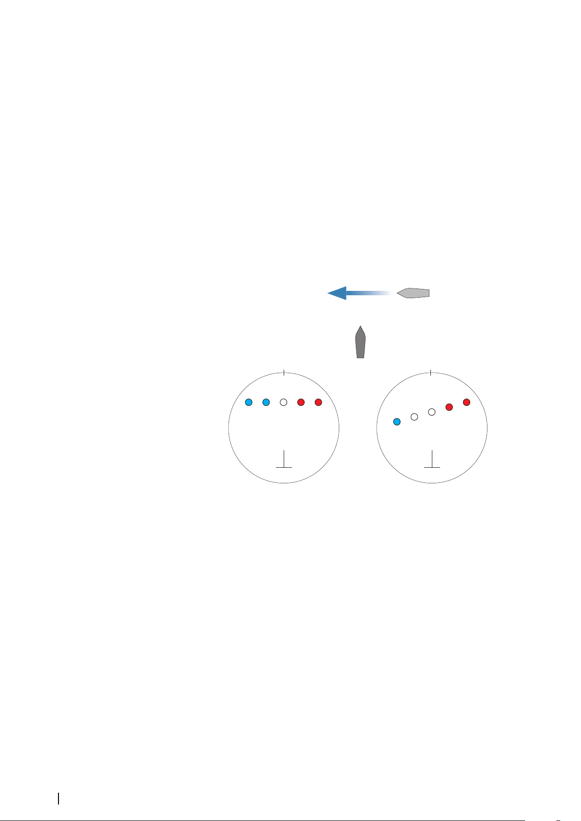
- White/Red palette - Yellow
C
A
B
D
123
0°
45 1
2
3
4
5
0°
Black/Green palette - Red
-
- Black/Yellow palette - Red
VelocityTrack settings
Use this dialog to set speed thresholds of targets to be colored.
The speed threshold can be defined to apply for the radar source of the selected radar panel
only, or to all radar sources connected to the system. The setting is only applied to those
radars powered and connected at the time the setting is made. If the all radar sources option
is selected, newly connected radars will use the specified values automatically.
VelocityTrack examples
Approaching and diverging moving targets can be indicated as neutral (not colored) in some
circumstances. The navigator should be aware of these situations to safely use the
VelocityTrack feature as an aid for collision avoidance.
Examples of how VelocityTrack behaves in 2 navigation scenarios is illustrated below. The
illustrations show a target (A) crossing own vessel's (B) path.
The examples show the target movement (1-5) over 5 radar scans with the radar in relative
motion mode.
In example C, own vessel COG is 0°, and speed is 0 knots.
In example D, own vessel COG is 0°, and speed is 10 knots.
In both examples, the target COG is 270°, and the speed is 20 knots.
The colors in the examples are according to the colors used for black/green and black/yellow
radar palettes:
• Red (C1/C2 and D1/D2), indicating the target is on an approaching path to own vessel. Its
relative speed at that point is greater than the VelocityTrack speed threshold.
• Not colored (C3 and D3/D4), indicating it is temporarily neutral because its relative speed
at that point is less than the VelocityTrack speed threshold.
• Blue (C4/C5 and D5), indicating the target is diverging away from own vessel and its
relative speed at that point is greater than the VelocityTrack speed threshold.
Radar symbology
Radar symbology defined in the Radar Settings panel can be turned on/off collectively. See
80
the radar panel illustration showing optional radar items.
Radar| Zeus³S Operation Manual
Page 81

Target trails
You can set how long the trails generated from each target on your radar panel remain. You
can also turn OFF target trails.
Note: True motion is recommended when using Target trails
Ú
Clearing target trails from the panel
When target trails are displayed on the panel, the radar menu expands to include an option
where you can clear target trails from your radar panel temporarily. The target trails start to
appear again unless you switch them off as described above.
The radar palette
Different colors (palettes) can be used to represent detail on your radar panel.
Radar orientation
Radar orientation is indicated on the upper left corner of the radar panel as either HU
(Heading UP), NU (North Up) or CU (Course up).
Head-up
In head-up mode, the heading line on the PPI is oriented on the 0° on the bearing scale and
towards the top of the screen. The radar image is displayed relative to own ship, and when
the ship turns the radar image rotates.
Note: Head-up is only available in relative motion mode, and it is the only orientation
Ú
mode available if the radar is not connected to a heading source.
North up
In North up mode the 0° indication on the PPI represents north. The heading line on the PPI
is oriented according to own ship heading obtained from the compass. When the ship turns
the heading line changes its direction according to the ship's heading, while the radar image
remains stabilized.
The North up orientation is not available if no heading source is connected to the radar. If
heading data is lost, the system will automatically switch to Head-up orientation.
Course up
In Course up mode, the top of the bearing scale indicates the ship’s true course measured
from north at the time Course up was activated. When the ship turns the bearing scale
remains fixed, while the heading line rotates with the ship's yawing and course change.
The Course up orientation is reset by re-selecting the Course up mode.
Radar motion mode
Radar motion is indicated on the upper left corner of the radar panel as either TM (True
motion) or RM (Relative motion).
Relative motion
In relative motion your vessel remains in a fixed location on the Radar PPI, and all other
objects move relative to your position.
You select the position of the fixed location as described in "Offsetting the PPI center" on page 82.
True motion
In true motion your vessel and all moving targets move across the Radar PPI as you travel. All
stationary objects remain in a fixed position. When the vessel’s symbol reaches 75% of the
PPI radius (A), the radar image is redrawn with the vessel symbol re-positioned (B) 180°
opposite the current heading bearing.
Radar| Zeus³S Operation Manual
81
Page 82
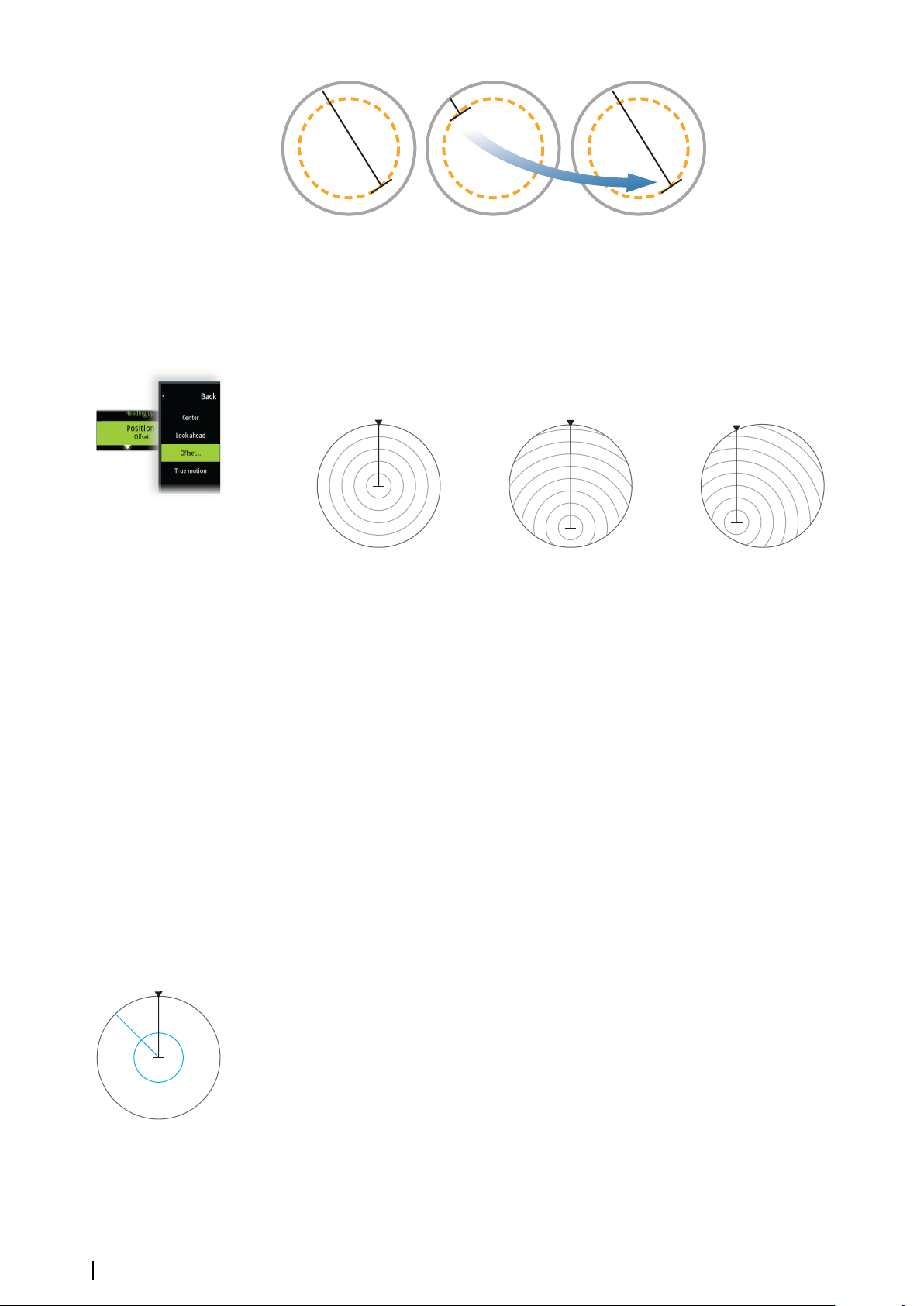
A
B
When true motion is selected, the true motion reset option is available from the menu. This
allows for manually resetting the radar image and vessel symbol to its starting position.
Note: True motion is only available when the PPI is in either north up or course up
Ú
orientation mode.
Offsetting the PPI center
You can set the antenna position origin to a different location on the radar PPI. The options
described in the next sections are available.
PPI center: Center PPI center: Look Ahead PPI Center: Offset
Note: The bearing scale is according to the Consistent Common Reference Point (CCRP),
Ú
while the offset sets the radar antenna position on the PPI. The maximum off-centering
allowed is 75% of the radius at the current range. This may result in the CCRP being
outside of the bearing scale. In such cases the measurements are still taken by the CCRP
and the bearing scale is compressed accordingly.
Center
The Center option resets the antenna position to the center of the PPI.
Look ahead
The Look ahead option is used to maximize the view ahead of the vessel. When selected the
PPI center is placed at 70% of the radius of the PPI, 180° opposite the top of the display.
Note: Look ahead is only available for Heading Up radar orientation.
Ú
Offset
This option allows you to use the cursor for selecting the PPI center.
Move the cursor to the preferred offset position, and confirm your selection.
EBL/VRM markers
The electronic bearing line (EBL) and variable range marker (VRM) allows quick
measurements of range and bearing to vessels and landmasses within radar range. Two
different EBL/VRMs can be placed on the radar image.
The EBL/VRMs are by default positioned from the center of the vessel. It is, however, possible
to offset the reference point to any selected position on the radar image.
When positioned, you can turn the EBL/VRM on/off by selecting the relevant markers on the
data bar, or by deselecting the marker from the menu.
Defining an EBL/VRM marker
1. Ensure that the cursor is not active
2. Activate the menu, select EBL/VRM, then select EBL/VRM 1 or EBL/VRM 2
-
The EBL/VRM is now positioned on the radar image
82
Radar| Zeus³S Operation Manual
Page 83
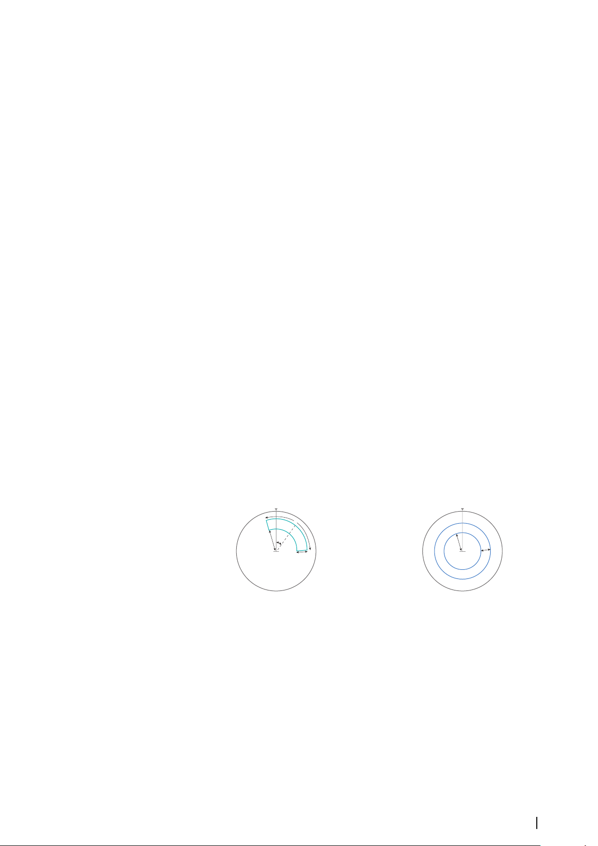
3. Select the adjustment option from the menu if you need to reposition the marker, then
C
B
A
D
B
C
adjust the marker by dragging it into position on the radar image
4. Select the save option to save your settings
Placing EBL/VRM markers by using the cursor
1. Position the cursor on the radar image
2. Activate the menu
3. Select one of the EBL/VRM markers
-
The EBL line and the VRM circle are positioned according to the cursor position.
Offsetting an EBL/VRM marker
1. Ensure that the cursor is not active
2. Activate the menu, select EBL/VRM, then select the marker you wish to offset
3. Select the set offset option
4. Position the cursor on the radar panel to set the offset position
5. Select the save option to save your settings.
You can reset the EBL/VRM center to vessel position from the menu.
Setting a guard zone around your vessel
A guard zone is an area (either circular or a sector) that you can define on the radar image.
When activated, an alarm alerts you when a radar target enters or exits the zone.
Defining a guard zone
1. Ensure that the cursor is not active
2. Activate the menu, select Guard zones, then select one of the guard zones
3. Select the shape for the zone
- The adjustment options depend on the guard zone shape
4. Select Adjust to define the settings for the guard zone. The values can be set from the
menu or by dragging on the radar panel.
- A: Bearing, relative to the vessel heading
- B: Depth
- C: Range, relative to vessel center
- D: Width
5. Select the save option to save your settings.
Shape: Sector
Shape: Circle
Alarm settings
An alarm is activated when a radar target breaches the guard zone limits. You can select if
the alarm is activated when the target enters or exits the zone.
Sensitivity
The guard zone sensitivity can be adjusted to eliminate alarms for small targets.
MARPA targets
If the system includes a heading sensor, the MARPA function (Mini Automatic Radar Plotting
Aid) can be used to track up to ten radar targets.
You can set alarms to notify you if a target gets too close. Refer to "Radar settings"
MARPA tracking is an important tool for collision avoidance.
Radar| Zeus³S Operation Manual
on page 85.
83
Page 84
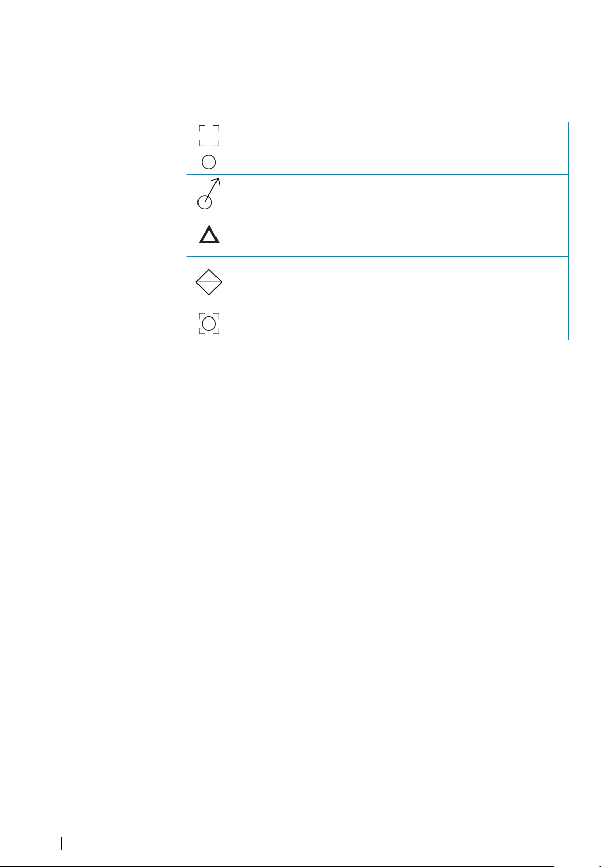
Note: MARPA requires heading data for both the radar and the unit.
Ú
MARPA target symbols
The system uses the target symbols shown below.
Acquiring MARPA target. Typically it takes up to 10 full rotations of the scanner.
Tracking MARPA target, not moving or at anchor.
Tracking and safe MARPA target with extension lines.
Dangerous MARPA target.
A target is defined as dangerous when it enters the guard zone defined on the
radar panel.
When no signals have been received within a time limit a target will be defined
as lost.
The target symbol represents the last valid position of the target before the
reception of data was lost.
Selected MARPA target, activated by positioning the cursor on the target icon.
The target returns to the default target symbol when the cursor is removed.
Tracking MARPA targets
1. Position the cursor on the target on the radar image
2. Select Acquire targets from the menu
3. Repeat the process if you want to track more targets
After your targets are identified, it may take up to 10 radar sweeps to acquire and then track
the target.
Cancelling MARPA target tracking
When targets are being tracked, the radar menu expands to include options for cancelling
individual targets or to stop the tracking function.
Cancel tracking individual targets by selecting the target icon before activating the menu.
Viewing MARPA target information
If the pop-up is activated, you can select a MARPA target to display basic target information.
Information for the 3 MARPA targets closest to the vessel is also displayed in the data bar.
When a target is selected, detailed information for the target can be displayed from the
menu.
You can display information about all MARPA targets by using the Vessels tool option on the
Home page.
MARPA alarm settings
You can define the following MARPA alarms:
• MARPA target lost
Controls whether an alarm is activated when a MARPA target is lost.
• MARPA unavailable
Controls whether an alarm is activated if you do not have the required inputs for MARPA
to work (valid GPS position and heading sensor connected to the radar server).
84
Recording radar data
You can record radar data and save the file internally in the unit, or save it onto a storage
device connected to the unit.
A recorded radar file can be used for documenting an event or an operational error. A logged
radar file can also be used by the simulator.
Radar| Zeus³S Operation Manual
Page 85
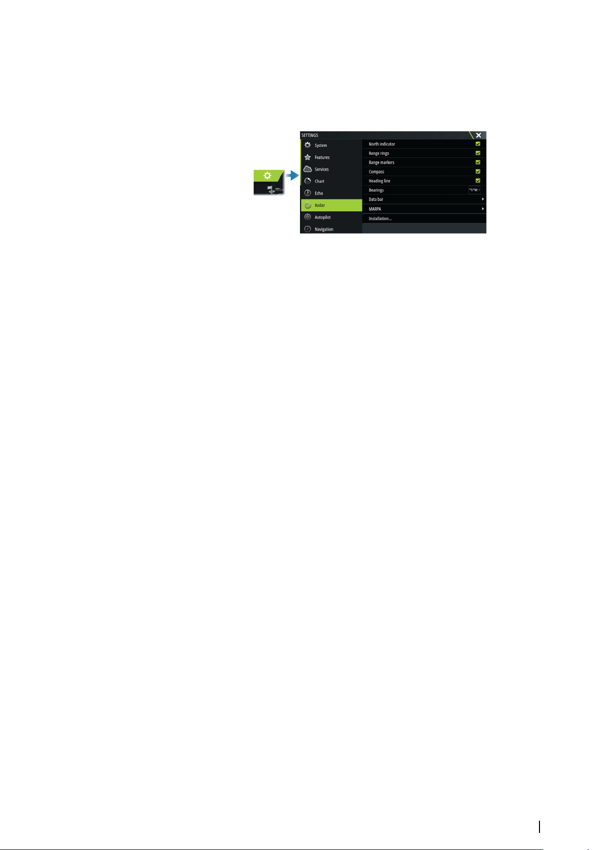
Note: The record menu option is available if recording is turned on in the Advanced
Ú
system settings.
If more than one radar is available, you can select which source you want to record.
Radar settings
Radar symbology
You can select which optional radar items that should be turned on/off collectively from the
menu. Refer to the Radar panel illustration.
Bearings
Used for selecting whether the radar bearing should be measured in relation to True/
Magnetic North (°T/°M) or to your relative heading (°R).
Data bar
Turns on/off the radar data bar. Refer to the radar panel illustration.
The data bar can show up to 3 targets, arranged with the most dangerous targets on top.
You can select to show MARPA targets on top and before any AIS targets, even if the AIS
targets are closer to your vessel.
MARPA settings
History length
Trails can be used to visualize the previous positions of a tracked target.
The history length defines the time presentation of the trail.
Safe ring
A safe ring can be added around your vessel to present the danger zone. The radius of the
ring is the same as the closest point of approach as set in the Dangerous Vessels dialog. Refer
to "Defining dangerous vessels" on page 89.
Installation
The Installation option is used for radar installation, described in the separate Radar or the
unit's installation manuals.
Radar| Zeus³S Operation Manual
85
Page 86
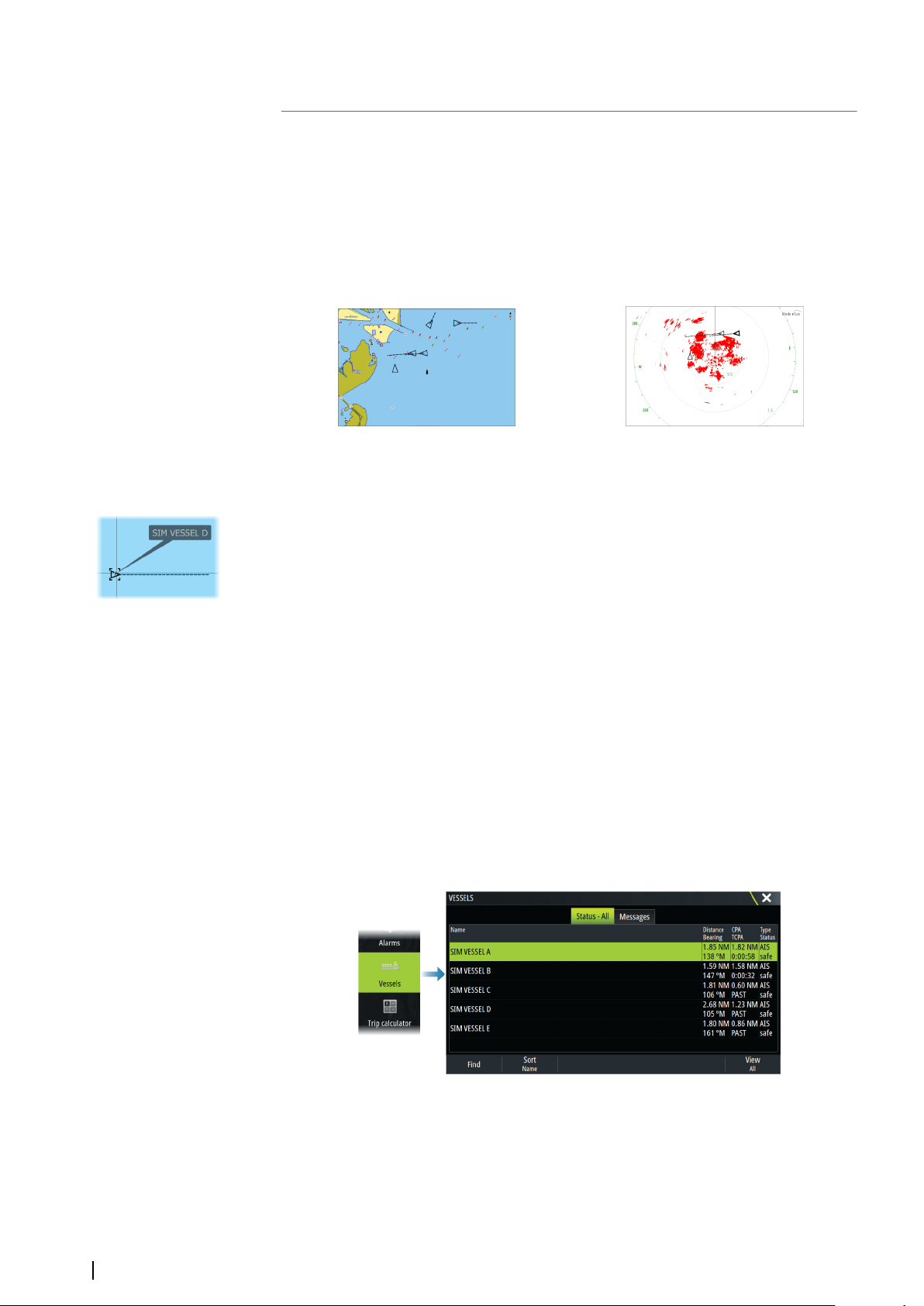
AIS
13
About AIS
If a compatible AIS (Automatic Identification System) is connected to the system, AIS targets
can be displayed and tracked. You can also see messages and position for DSC transmitting
devices within range.
AIS targets can be displayed as overlay on chart and radar images.
The AIS is an important tool for safe travelling and collision avoidance. You can set alarms to
notify you if an AIS target gets too close or if the target is lost.
AIS vessels on a chart panel AIS vessels on a radar panel
Selecting an AIS target
When you select an AIS icon, the symbol changes to selected target symbol. Only one target
can be selected at a time.
Note: Pop-up information must be enabled to see the vessel's name. Refer to "Chart
Ú
settings" on page 32.
Searching for AIS vessels
You can search for AIS targets by using the find option in the menu. If the cursor is active, the
system searches for vessels around the cursor position. Without an active cursor, the system
searches for vessels around your vessel's position.
Displaying target information
The vessels dialog
The vessels dialog displays a list of all targets.
By default, the dialog lists targets, arranged by distance to own vessel. You can select to
change the sort order, and to display only a selected target type.
The vessels dialog also lists received AIS messages.
86
AIS vessel details
Detailed information about an AIS target is available from the AIS vessels details dialog.
To display the dialog:
• select the AIS pop-up
• select the info option in the menu
AIS| Zeus³S Operation Manual
Page 87
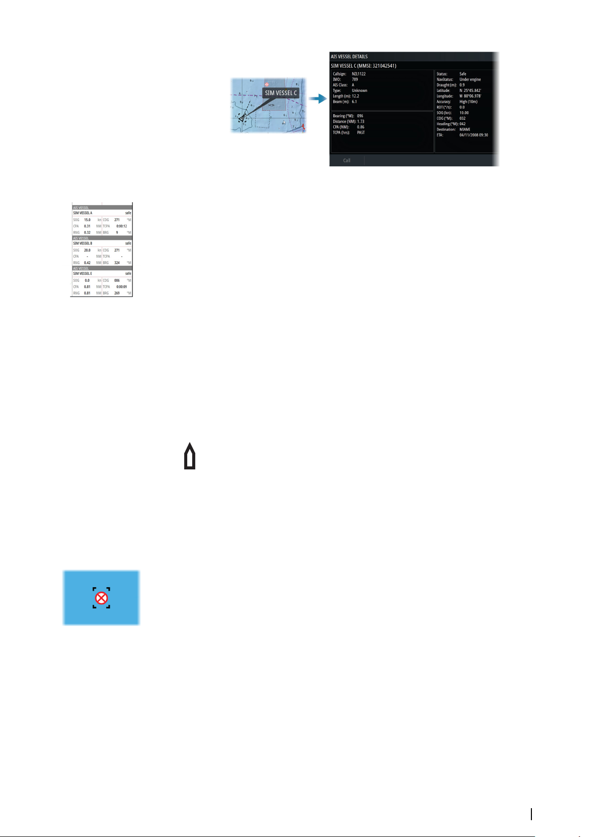
AIS information on radar panels
The radar data bar includes information about targets.
The targets are listed with the closest target on top, and are color coded to indicate target
status.
Calling an AIS vessel
If the system includes a VHF radio supporting DSC (Digital Select Calling) calls over NMEA
2000 or NMEA 0183, a DSC call can be initiated to other vessels from the unit.
The call option is available in the AIS vessel details dialog, and in the vessel status dialog.
Refer to "Displaying target information" on page 86.
DSC Vessel tracking
DSC (Digital Selective Calling) is a semi-automated method of requesting or receiving
position data from a vessel with a DSC VHF radio. For more information on how to use this,
refer to your VHF radio manual.
There are various types of DSC position messages, including distress calls. The type of
message made determines information sent with the call, and how the radio and MFD
respond to the incoming call.
When a DSC message has been received, the MFD will display a DSC vessel icon
on the chart panel and radar panel at the received coordinates. In addition, some
radios will send COG and SOG with the position data. This allows for correct
orientation of the icon.
When receiving a distress message you will see an alarm box informing you that a message
has been received. This can be read under the messages tab on the vessels dialog. Select the
vessels button in the toolbar to display the vessels dialog.
AIS SART
When an AIS SART (Search and Rescue Transponder) is activated, it starts transmitting its
position and identification data. This data is received by your AIS device.
If your AIS receiver is not compliant with AIS SART, it interprets the received AIS SART data as
a signal from a standard AIS transmitter. An icon is positioned on the chart, but this icon is an
AIS vessel icon.
If your AIS receiver is compliant with AIS SART, the following takes place when AIS SART data
is received:
• An AIS SART icon is located on the chart in the position received from the AIS SART
• An alarm message is displayed
If you have enabled the siren, the alarm message is followed by an audible alarm.
Note: The icon is green if the received AIS SART data is a test and not an active message.
Ú
AIS SART alarm message
When data is received from an AIS SART, an alarm message is displayed. This message
includes the AIS SART’s unique MMSI number, and its position, distance, and bearing from
your vessel.
AIS| Zeus³S Operation Manual
87
Page 88
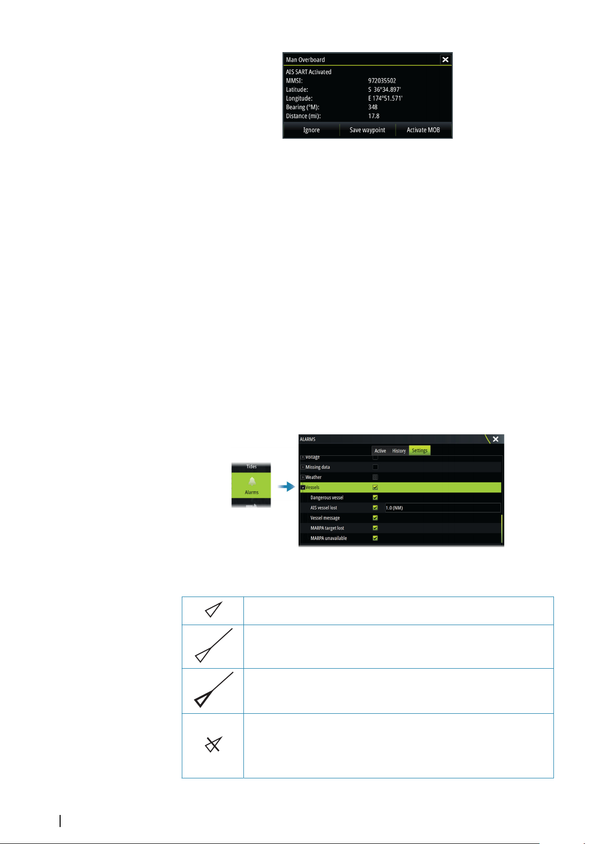
You have the following options:
• Ignore the alarm
-
The alarm is muted and the message closed. The alarm does not reappear
Note: If you ignore the alarm, the AIS SART icon remains visible on your chart, and the
Ú
AIS SART remains in the vessels list.
• Save the waypoint
- The waypoint is saved to your waypoint list. This waypoint name is prefixed with MOB
AIS SART - followed by the unique MMSI number of the SART. For example, MOB AIS
SART - 12345678.
• Activate the MOB function
- The display switches to a zoomed chart panel, centered on the AIS SART position
- The system creates an active route to the AIS SART position
Note: If the MOB function is already active, this will be terminated and replaced by the
Ú
new route towards the AIS SART position.
Note: If the AIS stops receiving the AIS SART message, the AIS SART remains in the
Ú
vessels list for 10 minutes after it receives the last signal.
Vessel alarms
You can define several alarms to alert you if a target shows up within predefined range limits,
or if a previously identified target is lost.
88
AIS target symbols
Safe AIS target with course extension line turned off. Bold lines indicates
dangerous AIS target.
Moving and safe AIS target with course extension line.
Dangerous AIS target, illustrated with bold line.
A target is defined as dangerous based on the CPA and TCPA settings. Refer
to “Defining dangerous vessels”.
Lost AIS target.
When no signals have been received within a time limit, a target is defined
as lost.
The target symbol represents the last valid position of the target before the
reception of data was lost.
AIS| Zeus³S Operation Manual
Page 89
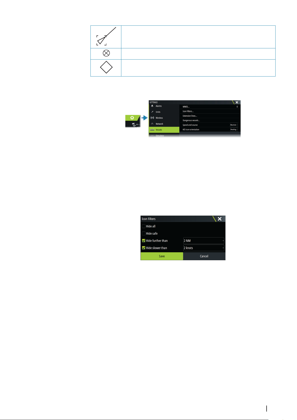
Selected AIS target, activated by selecting a target symbol.
+
The target returns to the default target symbol when the cursor is removed
from the symbol.
AIS SART (AIS Search And Rescue Transmitter).
AtoN (Aids To Navigation)
Vessel settings
MMSI
Used for entering your own MMSI (Maritime Mobile Service Identity) number into the system.
You need to have this number entered to receive addressed messages from AIS and DSC
vessels. You also need to have your MMSI number entered to avoid seeing your own vessel
as an AIS target.
Icon filters
By default, all targets are shown on the panel if an AIS device is connected to the system.
You can select not to show any targets, or to filter the icons based on security settings,
distance, and vessel speed.
Extension lines
Defines the length of course over ground and heading extension lines for your own vessel
and for other vessels.
The length of the extension lines is set to indicate the distance the vessel will move in the
selected time period.
Your own vessel heading information is read from the active heading sensor, and COG
information is received from the active GPS. For other vessels COG data is included in the
message received from the AIS system.
Defining dangerous vessels
You can use the CPA (Closest point of approach) and TCPA (Time to closest point of
approach) values to define when a target should be considered as dangerous. When a target
comes within the distance for CPA or within the time limit for TCPA, the symbol changes to
the dangerous target symbol.
AIS| Zeus³S Operation Manual
89
Page 90
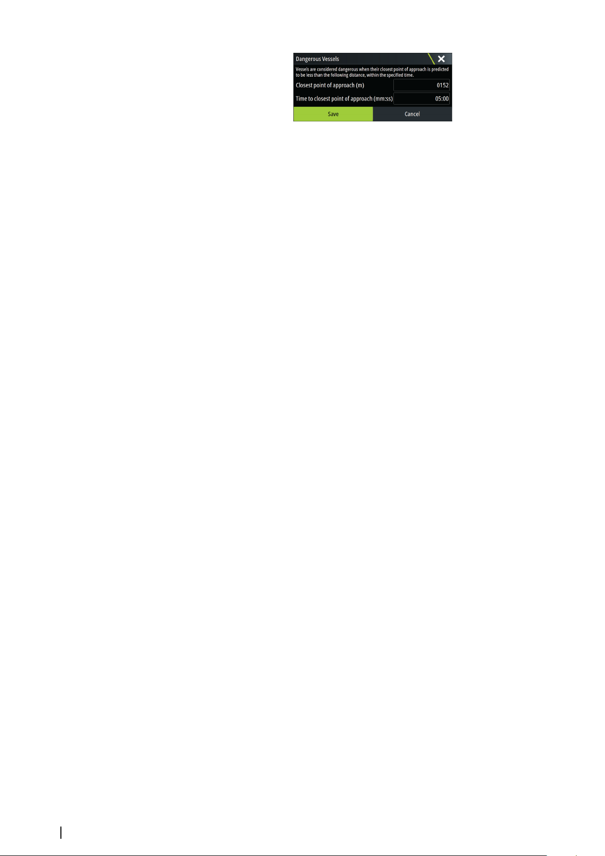
Speed and course
The extension line can be used to indicate speed and course for targets, either as absolute
(true) motion or relative to your vessel.
AIS icon orientation
Sets the orientation of the AIS icon, either based on heading or COG information.
90
AIS| Zeus³S Operation Manual
Page 91
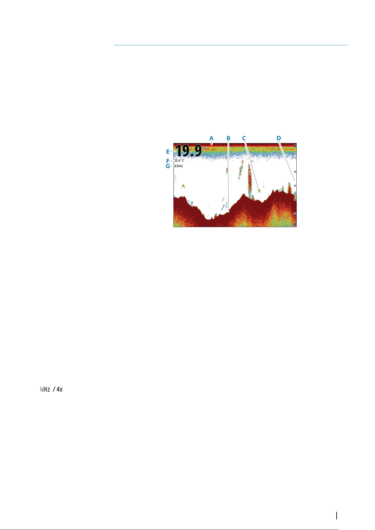
Echosounder
14
About
The echosounder function provides a view of the water and bottom beneath your vessel,
allowing you to detect fish and examine the structure of the sea floor.
Requirements
The unit has a built-in echosounder. A compatible echosounder transducer is required.
The image
A Surface
B Bottom
C Fish arches
D Range scale
E Depth
F Temperature
G Frequency
Multiple sources
You can specify the source for the image in the active panel. You can display different
sources simultaneously using a multi-panel page configuration.
For more information on how to select the source for a panel, refer to "Source" on page 94.
Zooming the image
You can zoom the image.
The zoom level is shown on the image. If the cursor is active, the system zooms in where the
cursor is positioned.
Echosounder| Zeus³S Operation Manual
91
Page 92
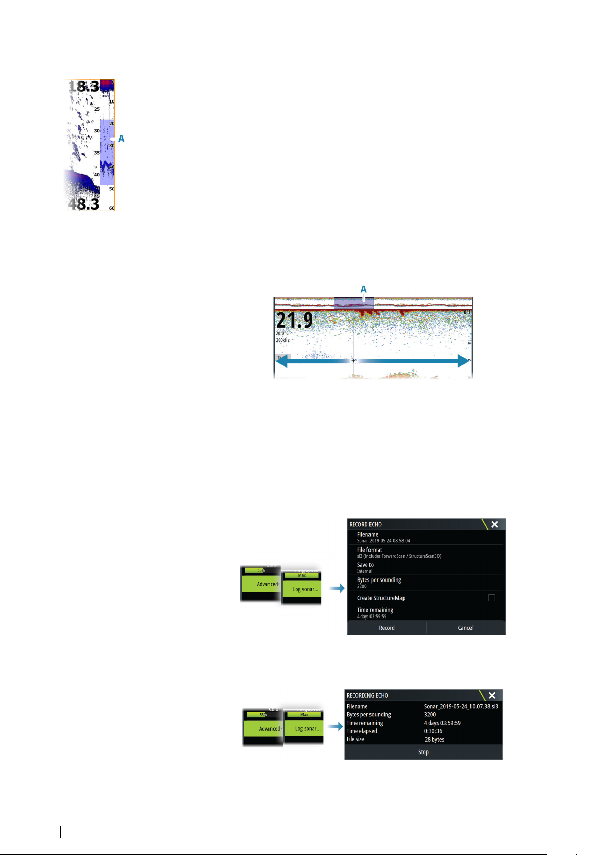
Zoom bar
The zoom bar (A) is displayed when you zoom the image.
Drag the zoom bar vertically to view different parts of the water column.
Using the cursor on the panel
By default, the cursor is not shown on the image.
When you position the cursor on the panel, the image pauses and the cursor information
window is activated. The depth and range of the cursor is shown at the cursor position.
Viewing history
Whenever the cursor is shown on the panel, the history bar (A) is shown at the top of the
panel. The history bar shows the image you are currently viewing in relation to the total
image history stored.
You can view history by panning the image.
To resume normal scrolling, clear the cursor.
Recording log data
Start recording log data
You can start recording log data and save the file internally in the unit, or save it onto a
storage device connected to the unit.
When the data is being recorded, there is a flashing red symbol in the top left corner and a
message appears periodically at the bottom of the screen.
Specify recording settings in the recording dialog.
Stop recording log data
Use the stop logging option to stop recording log data.
92
Echosounder| Zeus³S Operation Manual
Page 93
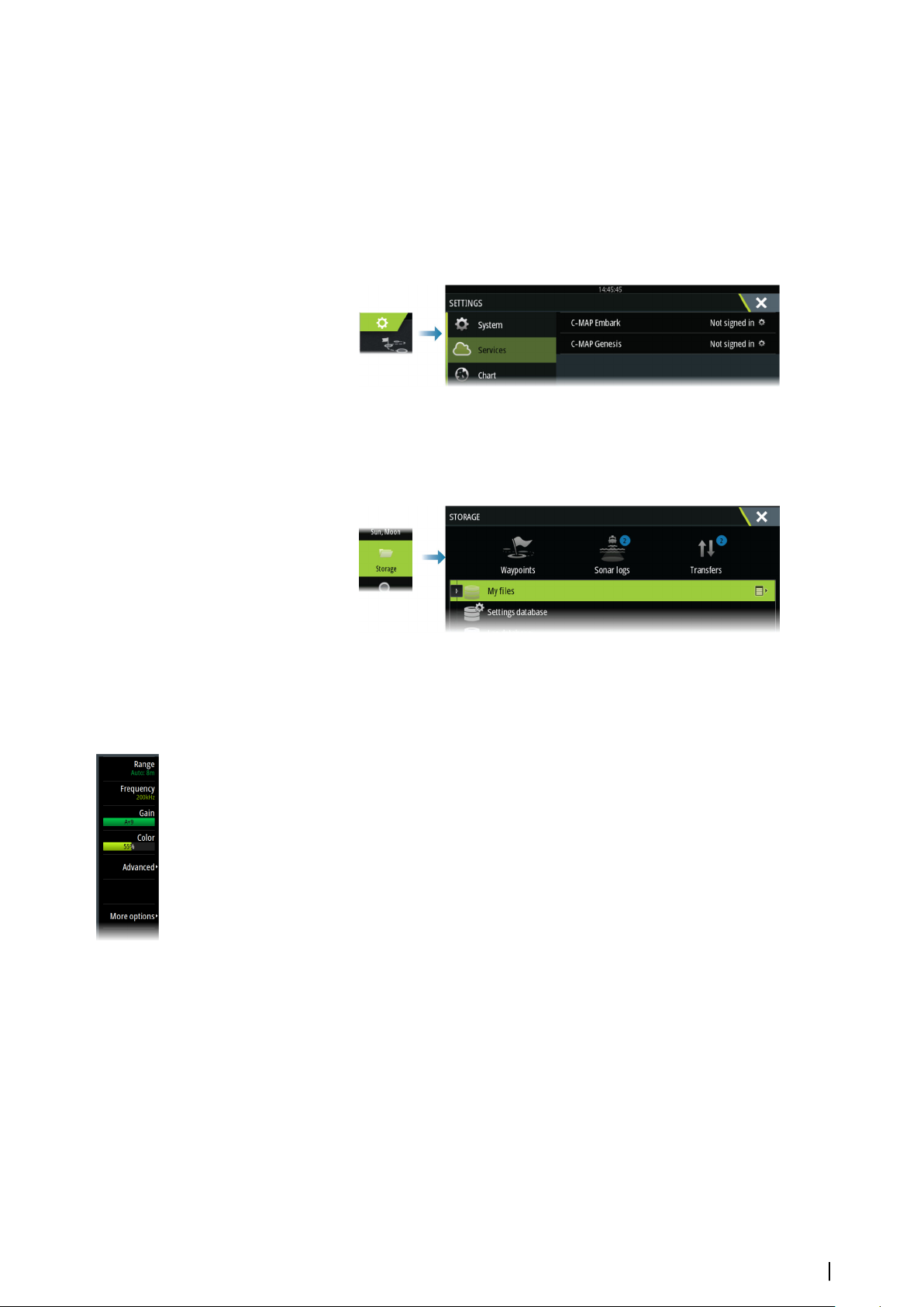
Viewing recorded data
Both internally and externally stored sounder records can be reviewed when the view sonar
log option is selected in the echo settings dialog. Refer to "Echosounder settings" on page 96.
Upload sonar logs to C-MAP Genesis
To upload sonar logs to C-MAP Genesis do one of the following:
• Use the services option. Follow the prompts to sign in and transfer the log files to C-MAP
Genesis.
• Use the Storage dialog. Select the sonar logs icon and the logs you want to transfer. If you
are already signed in to C-MAP Genesis the files are transferred. If you are not signed in,
select the transfers icon and follow the prompts to sign in and transfer the log files to CMAP Genesis. You can sign in and transfer files at a later time when the unit is connected
to the internet.
Customizing the image
Use the menu to customize the image. When the cursor is active, some options in the menu
are replaced with cursor mode features. Select the clear cursor option to return to the normal
menu.
Range
The range setting determines which water depth that is visible on the screen.
Note: Setting a deep range in shallow water may cause the system to lose track of the
Ú
depth.
Preset range levels
Select a preset range level manually from the menu.
Auto range
In auto range, the system automatically displays the whole range from the water surface to
the bottom.
Select the range option and then the auto option in the menu.
Custom range
This option allows you to manually set both upper and lower range limits.
Set a custom range by selecting the range menu option and then the custom option.
Note: Setting a custom range puts the system in manual range mode.
Ú
Frequency
The unit supports several transducer frequencies. Available frequencies depend on the
transducer model that is configured for use.
Echosounder| Zeus³S Operation Manual
93
Page 94
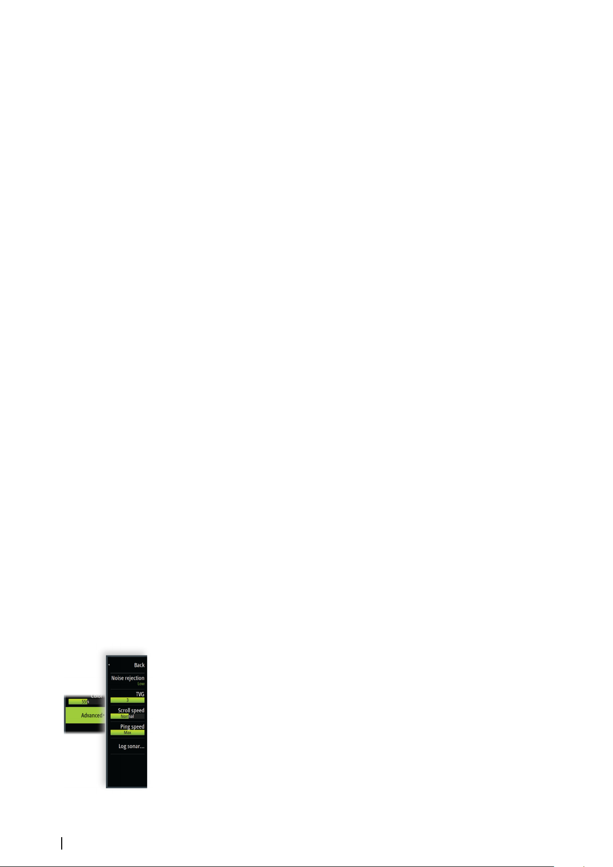
• A low frequency, for example 50 kHz, will go deep. It generates a wide cone but is more
sensitive to noise. It is good for bottom discrimination and wide area search.
• A high frequency, for example 200 kHz, offers higher discrimination and is less sensitive to
noise. It is good for separating targets and for higher speed vessels.
Gain
The gain controls the sensitivity. The more you increase the gain, the more details are shown
on the image. However, a higher gain setting may introduce more background clutter. If the
gain is set too low, weak echoes might not be displayed.
A manual and an automatic gain mode are available. By default, the gain is set to Auto.
Color
Strong and weak echo signals have different colors to indicate the different signal strengths.
The colors used depend on which palette you select.
The more you increase the color setting, the more echoes are displayed in the color at the
strong return end of the scale.
Source
Note: Available only if multiple sources with the same capability are available.
Ú
Used to specify the source for the image in the active panel.
You can display different sources simultaneously, using a multi-panel page configuration.
Menu options for each panel are independent.
Note: Using transducers at the same frequency can cause interference.
Ú
For source setup information, refer to the Zeus³S Installation Manual.
Measuring distance
The cursor can be used to measure the distance between the positions of two observations
on the image.
1. Position the cursor on the point from where you want to measure the distance
2. Select the measure menu option
Note: The measure option is not available unless the cursor is placed on the image.
Ú
3. Position the cursor on the second measuring point
-
A line is drawn between the measuring points, and the distance listed in the Cursor
Information window
4. Continue selecting new measuring points if required
Use menu options to re-position the start point and the end point as long as the measuring
function is active.
Select the finish measuring menu option to resume normal image scrolling.
Advanced options
The Advanced menu option is only available when the cursor is not active.
Noise rejection
Filters out signal interference and reduces on-screen clutter.
94
TVG
Wave action and boat wakes can cause onscreen clutter near the surface. The TVG (Time
Variable Gain) option reduces surface clutter by decreasing the sensitivity of the receiver near
the surface.
Scroll speed
You can select the scrolling speed of the image on the screen. A high scroll speed updates
the image fast, while a low scroll speed presents a longer history.
Echosounder| Zeus³S Operation Manual
Page 95
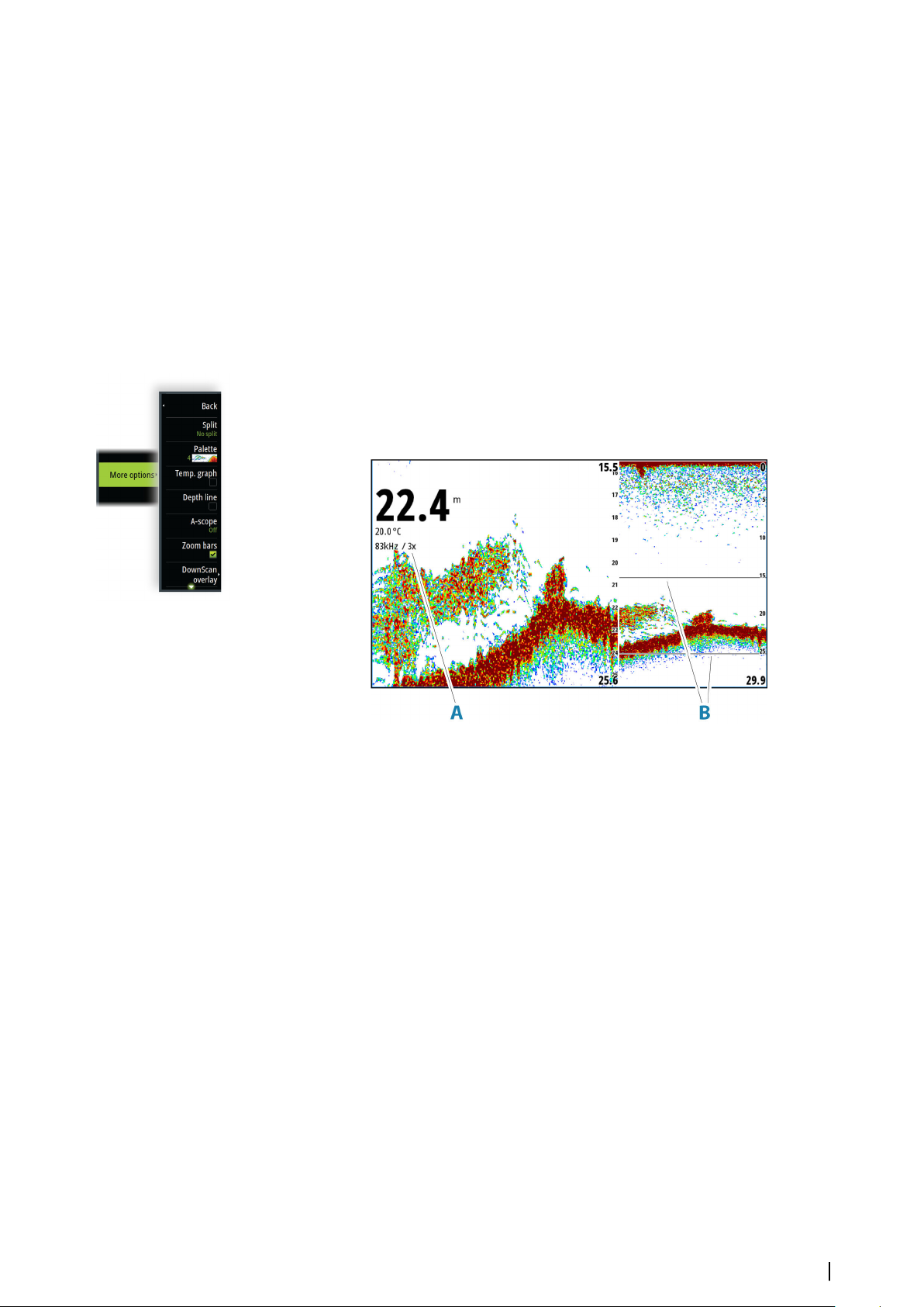
Note: In certain conditions it may be necessary to adjust the scroll speed to get a more
Ú
useful image. Such as adjusting the image to a faster speed when vertically fishing
without moving.
Ping Speed
Ping speed controls the rate the transducer transmits the signal into the water. By default,
the ping speed is set to max. It may be necessary to adjust the ping speed to limit
interference.
Log sonar
Select to start and stop recording of echosounder log data. For more information, refer to
"Recording log data" on page 92.
More options
Split screens
Zoom
A Zoom level
B Zoom bars
The Zoom mode presents a magnified view of the sounder image on the left side of the
panel.
By default, the zoom level is set to 2x. You can select up to 8x zoom.
The range zoom bars on the right side of the display shows the range that is magnified. If you
increase the zooming factor the range is reduced. You see this as reduced distance between
the zoom bars.
Move the zoom bars up/down on the image to view different depths of the water column.
Bottom lock
The bottom lock mode is useful when you want to view targets close to the bottom. In this
mode, the left side of the panel shows an image where the bottom is flattened. The range
scale is changed to measure from the seabed (0) and upwards. The bottom and the zero line
are always shown on the left image, independent of the range scale. The scaling factor for
the image on the left side of the panel is adjusted as described for the Zoom option.
Palettes
Used for selecting the image's color palette.
Temperature graph
The temperature graph is used to illustrate changes in water temperature.
Echosounder| Zeus³S Operation Manual
95
Page 96
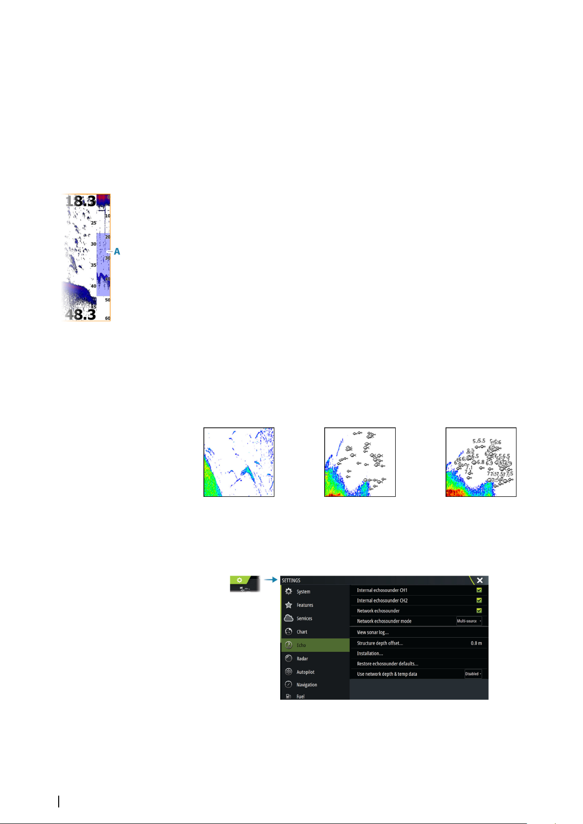
When toggled on, a colored line and temperature digits are shown on the image.
Depth line
When toggled on, a line is shown on the bottom surface. The depth line makes easier to
distinguish the bottom from fish and structures.
Amplitude scope
The amplitude scope is a display of an echo sounding on the panel. The strength of the
actual echoes are indicated by both width and color intensity.
Zoom bar
The zoom bar (A) is displayed when you zoom the image.
Drag the zoom bar vertically to view different parts of the water column.
Overlay DownScan
When a DownScan capable transducer is connected to your system, you can overlay
DownScan images on the regular Echosounder image.
When overlay DownScan is activated, the Echosounder panel menu expands to include basic
DownScan options.
Pause
Pauses the image, allowing you to examine the image in detail.
The pause function stops the echosounder from pinging. The system is not collecting data
when paused in this manner.
Fish ID
You can select how you want the fish targets to appear on the screen. You can also select if
you want to be notified by a beep when a fish ID appears on the panel.
Traditional fish arches Fish symbols Fish symbols and depth indication
Note: Not all fish symbols are actual fish.
Ú
Echosounder settings
96
Internal echosounder CH1 and CH2
When selected, the internal echosounder channel is available for selection in the
echosounder panel menu.
Echosounder| Zeus³S Operation Manual
Page 97
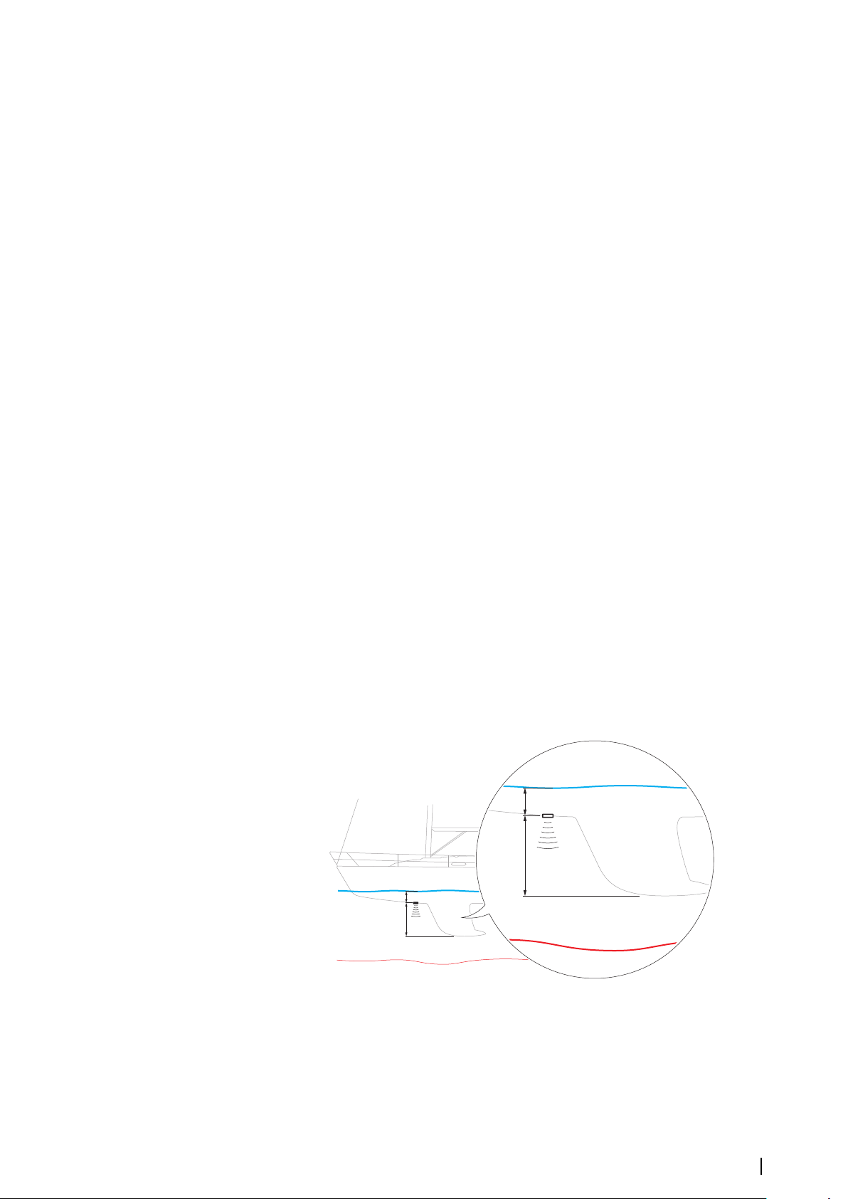
When unselected, this option disables the internal echosounder channel in the unit. It will
B
A
B
A
not be listed as an echosounder source for any unit on the network. Unselect this option for
channels with no transducer connected.
Network Echosounder
Select to share transducers from this unit with other units connected on the Ethernet
network. In addition, the setting must be selected in order to see other enabled sonar
devices on the network.
When unselected, transducers connected to this unit cannot be shared with other units
connected on the network, nor can it see other sources on the network that have this feature
enabled.
For more information about how to setup the echosounder, refer to the separate Installation
manual.
Network echosounder mode
The network echosounder mode setting selects whether only one or multiple echosounder
sources can be selected at the same time.
Note: Single source is automatically selected if there are older legacy echosounders on
Ú
the network. You cannot change this setting if older legacy echosounders are on the
network. Multi-source mode should be selected if no legacy echosounder is connected
to the network.
Note: When changing the mode to multi-source you must wait 30 seconds and then
Ú
power down all sources for. Wait 1 minute, then restart all connected sources.
View sonar log
Used to view recordings. The log file is displayed as a paused image, and you control the
scrolling and display from the menu.
You can use the cursor on the image, measure distance, and set view options as on a live
image. If more than one channel was recorded in the selected log file, you can select which
channel to display.
Structure depth offset
All transducers measure water depth from the transducer to the bottom. As a result, water
depth readings do not account for the distance from the transducer to the lowest point of
the boat in the water or from the transducer to the water surface.
• To show the depth from the lowest point of the vessel to the bottom, set the offset equal
to the vertical distance between the transducer and the lowest part of the vessel, A
(negative value).
• To show the depth from the water surface to the bottom, set the offset equal to the
vertical distance between the transducer and the water surface, B (positive value)
• For depth below transducer, set the offset to 0.
Echosounder| Zeus³S Operation Manual
97
Page 98

Installation
Used for installation and setup. See the separate Installation manual.
Restore echosounder defaults
Restore echosounder settings to the factory supplied defaults.
Use network depth and temp data
Selects from which network source depth and temperature data is shared on the NMEA 2000
network.
ForwardScan installation
Available when the ForwardScan feature is connected.
For setup information, refer to "ForwardScan installation settings" on page 101.
98
Echosounder| Zeus³S Operation Manual
Page 99
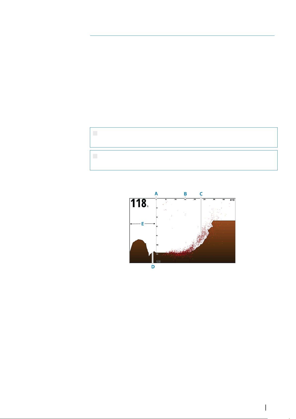
ForwardScan
15
About ForwardScan
ForwardScan sonar is a navigational aid that helps you monitor the underwater environment
in front of your vessel while carrying out slow speed maneuvers.
To use the ForwardScan feature you must have a ForwardScan transducer mounted on your
vessel.
With dual sonar capability a sonar/CHIRP and a ForwardScan transducer can be connected
directly to the unit.
The ForwardScan transducer must be connected to a compatible sonar module (or another
unit which has built-in sonar shared over the network).
If you have both a sonar/CHIRP and a ForwardScan transducer connected to different sonar
modules (or another unit which has built-in sonar shared over the network), you can view
both simultaneously on a single device.
Warning: Do not rely on this equipment as your principle source of
navigation or hazard detection.
Warning: Do not use this equipment to gauge depth or other conditions
for swimming or diving.
The ForwardScan image
A Depth range scale and vessel position
B Forward range scale
C Point data
D Bottom
E Depth history
ForwardScan| Zeus³S Operation Manual
99
Page 100
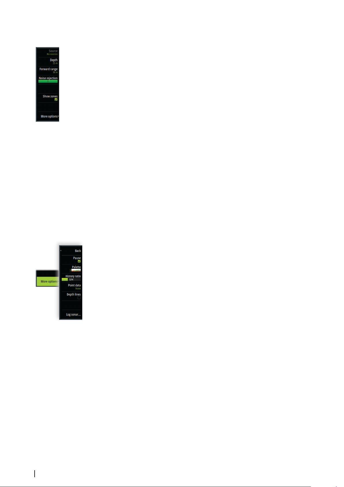
Setting up the ForwardScan image
Source
Note: Available only if multiple sources with the same capability are available.
Ú
Used to specify the source for the image in the active panel.
You can display different sources simultaneously, using a multi-panel page configuration.
Menu options for each panel are independent.
Note: Using transducers at the same frequency can cause interference.
Ú
For source setup information, refer to the Zeus³S Installation Manual.
Depth
Controls depth range. Depth range is set to auto mode by default.
Forward range
Controls the forward looking search range. Maximum Forward range is 91 meters (300 feet).
Noise rejection
Filters out signal interference and reduces on-screen clutter.
Show zones
Displays warning zones (yellow) and critical zones (red) on the screen. Refer to "Critical forward
range and Critical depth" on page 101.
More options
Pause
Pauses the image, allowing you to examine the image in detail.
The pause function stops the echosounder from pinging. The system is not collecting data
when paused in this manner.
Palettes
Used for selecting the image's color palette.
History ratio
Controls how much sounder history is shown behind the boat. The higher the ratio, the more
history will be shown.
Point data
By default, ForwardScan only shows the bottom. Select this option to specify to view no
sounder data points, all data points, or only points (objects) in the water column.
Depth lines
Displays lines on the screen that make it easier to quickly estimate depth and the underwater
objects.
100
Recording ForwardScan data
Displays the record dialog. ForwardScan log data can be recorded by selecting the correct
file format (sl3) in the record dialog. For more information, refer to "Recording log data" on page
92.
ForwardScan| Zeus³S Operation Manual
 Loading...