

B&G Zeus3 Glass Helm Installation Manual

ENGLISH
Zeus3 Glass Helm
Installation Manual
www.bandg.com


Preface
Disclaimer
As Navico is continuously improving this product, we retain the right to make changes to the
product at any time which may not be reflected in this version of the manual. Please contact
your nearest distributor if you require any further assistance.
It is the owner’s sole responsibility to install and use the equipment in a manner that will not
cause accidents, personal injury or property damage. The user of this product is solely
responsible for observing maritime safety practices.
NAVICO HOLDING AS AND ITS SUBSIDIARIES, BRANCHES AND AFFILIATES DISCLAIM ALL
LIABILITY FOR ANY USE OF THIS PRODUCT IN A WAY THAT MAY CAUSE ACCIDENTS, DAMAGE
OR THAT MAY VIOLATE THE LAW.
This manual represents the product as at the time of printing. Navico Holding AS and its
subsidiaries, branches and affiliates reserve the right to make changes to specifications
without notice.
Governing language
This statement, any instruction manuals, user guides and other information relating to the
product (Documentation) may be translated to, or has been translated from, another
language (Translation). In the event of any conflict between any Translation of the
Documentation, the English language version of the Documentation will be the official
version of the Documentation.
Copyright
Copyright © 2018 Navico Holding AS.
Warranty
The warranty card is supplied as a separate document. In case of any queries, refer to the
brand website of your unit or system:
www.bandg.com.
Compliance Statement
This equipment complies with:
• CE under 2014/53/EU Directive
• The requirements of level 2 devices of the Radio communications (Electromagnetic
Compatibility) standard 2008
• Part 15 of the FCC Rules. Operation is subject to the following two conditions: (1) this
device may not cause harmful interference, and (2) this device must accept any
interference received, including interference that may cause undesired operation.
The relevant Declaration of conformity is available in the product's section at the following
website: www.bandg.com.
Industry Canada
This device complies with Industry Canada license-exempt RSS standard(s). Operation is
subject to the following two conditions: (1) this device may not cause interference, and (2)
this device must accept any interference, including interference that may cause undesired
operation of the device.
Le présent appareil est conforme aux CNR d’Industrie Canada applicables aux appareils radio
exempts de licence. L’exploitation est autorisée aux deux conditions suivantes: (1) l’appareil
ne doit pas produire de brouillage, et (2) l’utilisateur de l’appareil doit accepter tout
brouillage radioélectrique subi, même si le brouillage est susceptible d’en compromettre le
fonctionnement.
Warning
The user is cautioned that any changes or modifications not expressly approved by the party
responsible for compliance could void the user’s authority to operate the equipment.
Preface | Zeus3 Glass Helm Installation Manual
3

This equipment generates, uses and can radiate radio frequency energy and, if not installed
and used in accordance with the instructions, may cause harmful interference to radio
communications. However, there is no guarantee that the interference will not occur in a
particular installation. If this equipment does cause harmful interference to radio or television
reception, which can be determined by turning the equipment off and on, the user is
encouraged to try to correct the interference by one or more of the following measures:
• Reorient or relocate the receiving antenna
• Increase the separation between the equipment and receiver
• Connect the equipment into an outlet on a circuit different from that of the receiver
• Consult the dealer or an experienced technician for help
Countries of intended use in the EU
AT - Austria
BE - Belgium
BG - Bulgaria
CY - Cyprus
CZ - Czech Republic
DK - Denmark
EE - Estonia
FI - Finland
FR - France
DE - Germany
GR - Greece
HU - Hungary
IS - Iceland
IE - Ireland
IT - Italy
LV - Latvia
LI - Liechtenstein
LT - Lithuania
LU - Luxembourg
MT - Malta
NL - Netherlands
NO - Norway
PL - Poland
PT - Portugal
RO - Romania
SK - Slovak Republic
SI - Slovenia
ES - Spain
SE - Sweden
CH - Switzerland
TR - Turkey
UK - United Kingdom
Internet usage
Some features in this product use an internet connection to perform data downloads and
uploads. Internet usage via a connected mobile/cell phone internet connection or a pay-perMB type internet connection may require large data usage. Your service provider may charge
you based on the amount of data you transfer. If you are unsure, contact your service
provider to confirm rates and restrictions.
4
Preface | Zeus3 Glass Helm Installation Manual

Trademarks
Navico® is a registered trademark of Navico.
B&G® is a registered trademark of Navico.
Bluetooth® is a registered trademark of Bluetooth SIG, Inc.
FLIR® is a registered trademark of FLIR.
HDMI® and HDMI™, the HDMI Logo, and High-Definition Multimedia Interface are trademarks
or registered trademarks of HDMI Licensing LLC in the United States and other countries.
NMEA® and NMEA 2000® are registered trademarks of the National Marine Electronics
Association.
SD™ and microSD™ are trademarks or registered trademarks of SD-3C, LLC in the United
States, other countries or both.
Wi-Fi® is a registered trademark of the Wi-Fi Alliance®.
Navico product references
This manual refers to the following Navico products:
• Broadband Radar™ (Broadband Radar)
• Broadband Sounder™ (Broadband Sounder)
• DownScan Overlay™ (Overlay)
• GoFree™ (GoFree)
• StructureScan® (StructureScan)
About this manual
This manual is a reference guide for installing units.
Some features may not be activated or available for screenshots in the manual. As a result,
screenshots of menus and dialogs may not match the look of your unit.
Important text that requires special attention from the reader is emphasized as follows:
Ú
Note: Used to draw the reader’s attention to a comment or some important information.
Warning: Used when it is necessary to warn personnel that they should
proceed carefully to prevent risk of injury and/or damage to equipment/
personnel.
Preface | Zeus3 Glass Helm Installation Manual
5

Contents
7 Introduction
7
Parts included
8 Front controls
8 Connectors
9 Card reader
10 Installation
10 Installation guidelines
10 Bezel fitment and removal
11 Cable retainer installation
11 Panel mounting
11 Bracket mounting
12 Wiring
12 Wiring guidelines
12 Power connector details
15 USB connector details
15 NMEA 0183 connector details
16 NMEA 2000 connector details
17 J1939 connector details
18 Ethernet connector details
18 Video in connector details
19 HDMI connector details
20 Software setup
20 First time startup
20 Software setup sequence
20 Accessing the settings dialog
20 System settings
22 Alarms settings
22 Radar settings
24 Echosounder settings
27 Autopilot settings
27 Fuel settings
29 Wireless settings
31 Network settings
36 3rd party support
36 C-Zone
37 Appendix
37 Accessories
38 Supported data
42 Technical specifications
44 Dimensional drawings
6
Contents | Zeus3 Glass Helm Installation Manual
Introduction
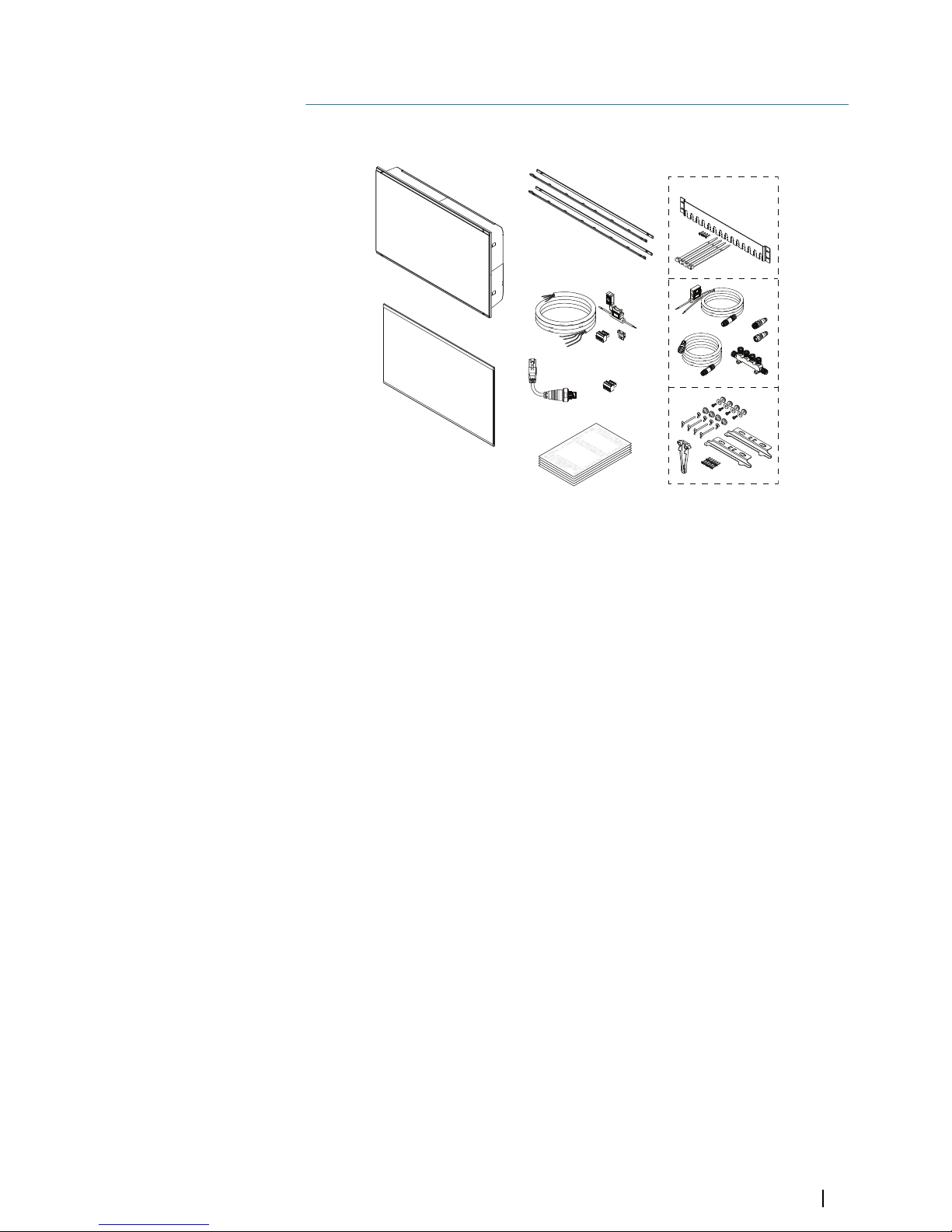
Parts included
A
C
D
H
I
J
B
ENGLISH
Installati
on Manual
bandg.c
om
ENGLISH
Installation
M
anua
l
bandg
.
com
E
NGLIS
H
Installa
ti
on Manual
bandg.com
ENGLISH
In
stall
ati
on Manual
band
g
.
c
om
F
G
E
A Display unit
B Suncover
C Bezels
• 1 set black bezels
• 1 set silver bezels
D Power cable, fuse, fuse holder and connector block
E RJ45 to 5-pin Ethernet adapter cable
F NMEA 0183 connector block
G Documentation pack
H Cable retainer kit
I NMEA 2000 starter kit
J Panel mounting kit
1
Introduction | Zeus3 Glass Helm Installation Manual
7
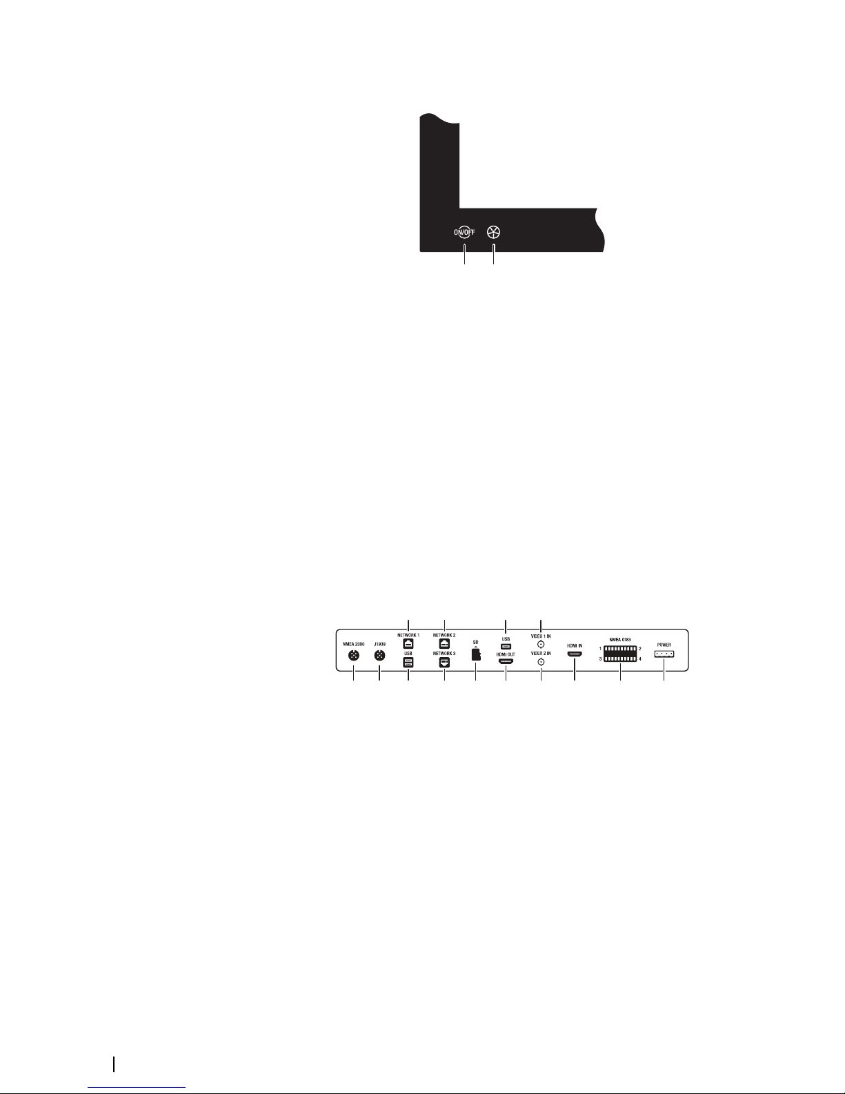
Front controls
B C
A
A Touch screen
B Power key
• Press and hold: turns the unit ON/OFF
• Short press once: displays the System Controls dialog
• Repeat short presses: toggles through preset dimming levels
C WheelKey - user configurable key, refer to "Configure WheelKey" on page 20.
Default without an autopilot connected to the system
• Short press: toggles between panels on split screen
• Long press: maximizes active panel on split screen
Default with an autopilot connected to the system
• Short press: opens the autopilot controller and puts the autopilot in standby
mode
• Long press: toggles between panels on split screen
Connectors
A B CCDDDE F GGH
JI
A NMEA 2000 - NMEA 2000 data
B J1939 - J1939 engine data
C USB - mouse, keyboard or mass storage
D NETWORK 1-3 - Ethernet network
E SD - microSD card reader
F HDMI OUT - HDMI video output
G VIDEO IN - composite video input
H HDMI IN - HDMI video input
I NMEA 0183 - NMEA 0183 data
J POWER - 12 - 24 V DC input, external alarm and power control
8
Introduction | Zeus3 Glass Helm Installation Manual
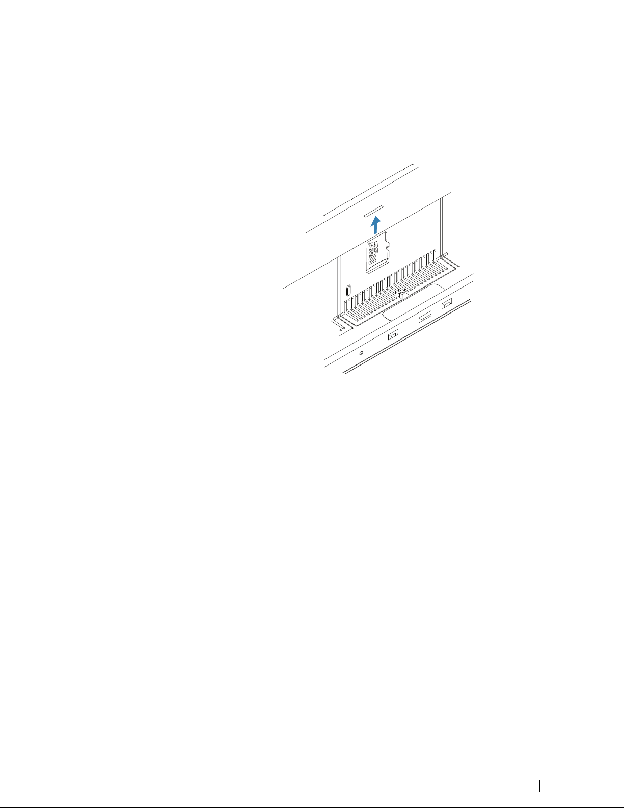
Card reader
A memory card can be used for detailed chart data, software updates, transfer of user data,
and system backup.
Ú
Note: Do not download, transfer or copy files to a chart card. Doing so can damage chart
information on the chart card.
If the card reader has a protective door it should always be securely shut immediately after
inserting or removing a card, in order to prevent possible water ingress.
Introduction | Zeus3 Glass Helm Installation Manual
9
Installation
Installation guidelines
Choose the mounting location carefully, make sure that there are no hidden electrical wires
or other parts behind the panel before you drill or cut. Ensure that any holes cut are in a safe
position and will not weaken the boat’s structure. If in doubt, consult a qualified boat builder,
or marine electronics installer.
Don´t:
• Mount any part where it can be used as a hand hold
• Mount any part where it might be submerged
• Mount any part where it will interfere with the operation, launching, or retrieving of the
boat
Do this:
• Test the unit in its intended location to ensure satisfactory wireless performance. Metal
and carbon materials are known to impact the performance in a negative way. A well
placed external wireless module can be added to overcome poor performance
• Consider the optimum viewing angles
• Consider the overall width and height requirements
• Consider access to the card reader
• Leave sufficient clearance to connect all relevant cables
• Check that it is possible to route cables to the intended mounting location
Ú
Note: Where flush mounted, the enclosure should be dry and well ventilated. In small
enclosures, it may be required to fit forced cooling.
Warning: Inadequate ventilation and subsequent overheating of the unit
may cause unreliable operation and reduced service life. Exposing the unit
to conditions that exceeds the specifications could invalidate your warranty.
Refer to the technical specifications in the "Appendix" on page 37.
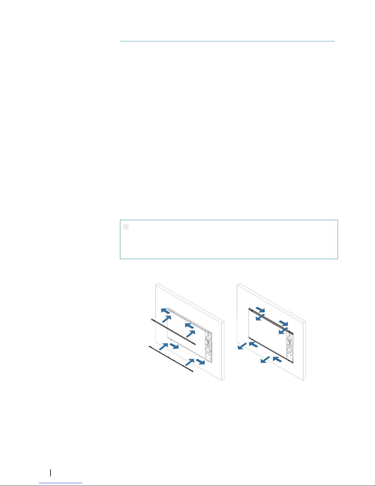
Bezel fitment and removal
Ú
Note: The unit in the illustration is an example only.
2
10
Installation | Zeus3 Glass Helm Installation Manual

Cable retainer installation
With the cable and plug fitted in place, secure the cable to the retention bracket using a
cable tie. Do not secure in such a way that it applies strain to the cable, or causes the plug or
socket to be bent out of alignment.
Panel mounting
Refer to the separate mounting template for panel mounting instructions.
Bracket mounting
For bracket mounting refer to separate documentation supplied with the bracket kit (sold
separately).
Installation | Zeus3 Glass Helm Installation Manual
11
Wiring
Wiring guidelines
Don't:
• Make sharp bends in the cables
• Run cables in a way that allows water to flow down into the connectors
• Run the data cables adjacent to radar, transmitter, or large/high current carrying cables or
high frequency signal cables.
• Run cables so they interfere with mechanical systems
• Run cables over sharp edges or burrs
Do this:
• Make drip and service loops
• Use cable-tie on all cables to keep them secure
• Solder/crimp and insulate all wiring connections if extending or shortening the cables.
Extending cables should be done with suitable crimp connectors or solder and heat
shrink. Keep joins as high as possible to minimize possibility of water immersion.
• Leave room adjacent to connectors to ease plugging and unplugging of cables
Warning: Before starting the installation, be sure to turn electrical power
off. If power is left on or turned on during the installation, fire, electrical
shock, or other serious injury may occur. Be sure that the voltage of the
power supply is compatible with the unit.
Warning: The positive supply wire (red) should always be connected to
(+) DC with the supplied fuse or a circuit breaker (closest available to fuse
rating).
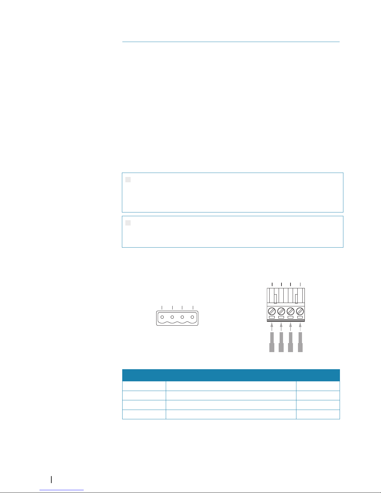
Power connector details
4
3 2 1
Unit socket (male)
4
3 2 1
Cable plug (female)
Pin Purpose Color
1 DC negative Black
2 +12/24 V DC Red
3 External alarm Blue
4 Power control Yellow
Power connection
The unit is designed to be powered by a 12 or 24 V DC system.
It is protected against reverse polarity, under voltage, and over voltage (for a limited
duration).
3
12
Wiring | Zeus3 Glass Helm Installation Manual
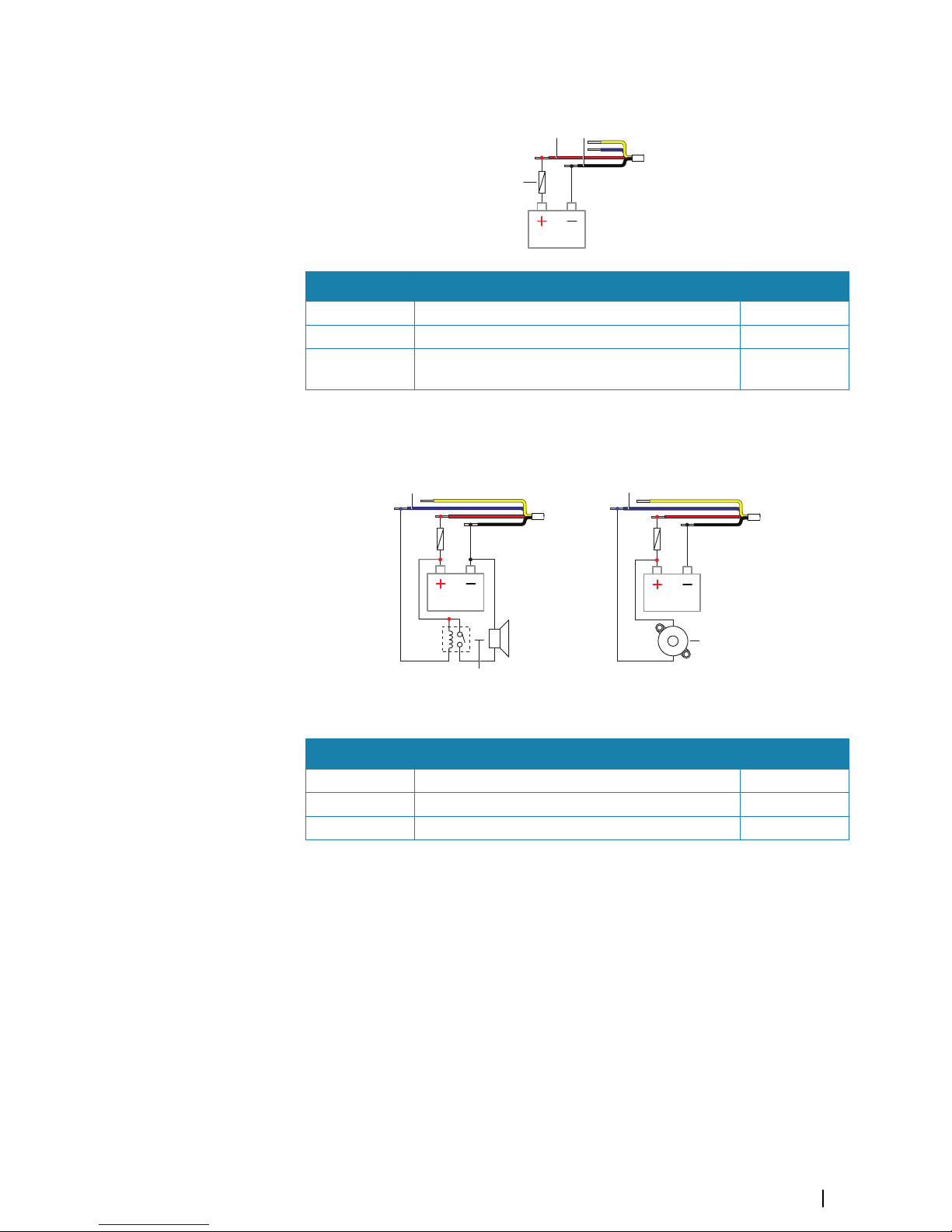
A fuse should be fitted to the positive supply, for recommended fuse rating refer to the
technical specification in the "Appendix" on page 37.
A B
C
Key Purpose Color
A +12/24 V DC Red
B DC negative Black
C Fuse, for recommended fuse rating refer to the
technical specification in the "Appendix" on page 37.
External alarm
A A
B
C
Siren Buzzer
For sirens that draw more than 1 A, use a relay.
Key Purpose Color
A External alarm output Blue
B Siren and relay
C Buzzer
Power control connection
The yellow wire in the power cable can be used to control how the unit is turned on and off.
Power controlled by power key
The unit will turn on/off when the power key on the unit is pressed.
Leave the yellow power control wire disconnected and tape or heat-shrink the end to
prevent shorting.
Power control by supply power
The unit will turn on/off without using the power key when power is applied/removed.
Connect the yellow wire to the red wire after the fuse.
Ú
Note: The unit cannot be powered down by power button, but can be put in to standby
mode (the screen backlight turns off).
Wiring | Zeus3 Glass Helm Installation Manual
13
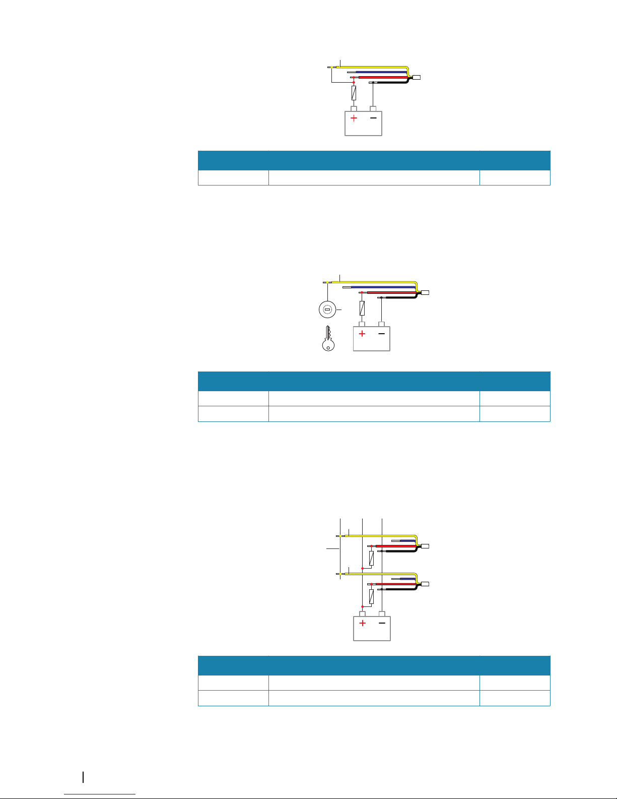
A
Key Purpose Color
A Power control wire, connected to supply power Yellow
Power controlled by ignition
The unit will turn on once ignition is turned on to start engines.
Ú
Note: Engine start batteries and house batteries should have a common ground
connection.
A
B
Key Purpose Color
A Power control wire Yellow
B Ignition switch
Power controlled by master slave bus
The yellow power control wire can either be an input that will turn on the unit when power
is applied, or an output that turns on other devices when the unit is powered on. It can be
configured at the installation stage to control the power state of displays and compatible
devices. When commissioning the system, the unit can be set to be a power control slave or
power control master.
A
A
B
Key Purpose Color
A Power control wire Yellow
B Master slave bus
If a unit is configured as power control master and turned on by the power key, it will output
voltage on the power control bus. This will power on both other power master units and
power slave units. If a unit is set to power control slave, it cannot be powered down using its
14
Wiring | Zeus3 Glass Helm Installation Manual
 Loading...