

B&G ZEUS3 Operator's Manual
Zeus
3
Operator Manual
ENGLISH
www.bandg.com


Preface
Disclaimer
As Navico is continuously improving this product, we retain the right to make changes to the
product at any time which may not be reflected in this version of the manual. Please contact
your nearest distributor if you require any further assistance.
It is the owner’s sole responsibility to install and use the equipment in a manner that will not
cause accidents, personal injury or property damage. The user of this product is solely
responsible for observing safe boating practices.
NAVICO HOLDING AS AND ITS SUBSIDIARIES, BRANCHES AND AFFILIATES DISCLAIM ALL
LIABILITY FOR ANY USE OF THIS PRODUCT IN A WAY THAT MAY CAUSE ACCIDENTS, DAMAGE
OR THAT MAY VIOLATE THE LAW.
Governing Language: This statement, any instruction manuals, user guides and other
information relating to the product (Documentation) may be translated to, or has been
translated from, another language (Translation). In the event of any conflict between any
Translation of the Documentation, the English language version of the Documentation will
be the official version of the Documentation.
This manual represents the product as at the time of printing. Navico Holding AS and its
subsidiaries, branches and affiliates reserve the right to make changes to specifications
without notice.
Trademarks
Navico® is a registered trademark of Navico.
B&G® is a registered trademark of Navico.
Navionics® is a registered trademark of Navionics, Inc.
NMEA® and NMEA 2000® are registered trademarks of the National Marine Electronics
Association.
SiriusXM® is a registered trademark of Sirius XM Radio Inc.
SimNet® is a registered trademark of Navico.
Fishing Hot Spots® is a registered trademark of Fishing Hot Spots Inc. Copyright© 2012
Fishing Hot Spots.
FUSION-Link™ Marine Entertainment Standard™ is a registered trademark of FUSION
Electronics Ltd.
C-MAP® is a registered trademark of C-MAP.
FLIR® is a registered trademark of FLIR.
SD™ and microSD™ are trademarks or registered trademarks of SD-3C, LLC in the United
States, other countries or both.
Wi-Fi® is a registered trademark of the Wi-Fi Alliance®.
Additional mapping data: Copyright© 2012 NSI, Inc.: Copyright© 2012 by Richardson’s
Maptech.
Bluetooth® is a registered trademark of Bluetooth SIG, Inc.
HDMI® and HDMI™, the HDMI Logo, and High-Definition Multimedia Interface are trademarks
or registered trademarks of HDMI Licensing LLC in the United States and other countries.
Navico product references
This manual can refer to the following Navico products:
• Broadband Radar™ (Broadband Radar)
• Broadband 3G™ Radar (Broadband 3G Radar)
• Broadband 4G™ Radar (Broadband 4G Radar)
• Broadband Sounder™ (Broadband Sounder)
• DownScan Imaging™ (DownScan)
• DownScan Overlay™ (Overlay)
Preface | Zeus3 Operator Manual
3

• ForwardScan™ (ForwardScan)
• GoFree™ (GoFree)
• Halo™ Pulse Compression Radar (Halo Radar)
• INSIGHT GENESIS® (Insight Genesis)
• SonicHub® (SonicHub)
• StructureMap™ (StructureMap)
• StructureScan® (StructureScan)
• StructureScan® HD (StructureScan HD)
Copyright
Copyright © 2016 Navico Holding AS.
Warranty
The warranty card is supplied as a separate document.
In case of any queries, refer to the brand website of your display or system: www.bandg.com.
Compliance statements
This equipment complies with:
• CE under 2014/53/EU Directive
• The requirements of level 2 devices of the Radio communications (Electromagnetic
Compatibility) standard 2008
• Part 15 of the FCC Rules. Operation is subject to the following two conditions: (1) this
device may not cause harmful interference, and (2) this device must accept any
interference received, including interference that may cause undesired operation.
The relevant Declaration of conformity is available in the product's section at the following
website: www.bandg.com.
Internet usage
Some features in this product use an internet connection to perform data downloads and
uploads. Internet usage via a connected mobile/cell phone internet connection or a pay-perMB type internet connection may require large data usage. Your service provider may charge
you based on the amount of data you transfer. If you are unsure, contact your service
provider to confirm rates and restrictions.
About this manual
The manual assumes that the user has basic knowledge of navigation, nautical terminology
and practices.
Important text that requires special attention from the reader is emphasized as follows:
Note: Used to draw the reader’s attention to a comment or some important information.
Ú
Warning: Used when it is necessary to warn personnel that they should
proceed carefully to prevent risk of injury and/or damage to equipment/
personnel.
Manual version
This manual is written for software version 1.0. The manual is continually updated to match
new software releases. The latest available manual version can be downloaded from
www.bandg.com.
Viewing the manual on the screen
The PDF viewer included in the unit makes it possible to read the manuals and other PDF
files on the screen. Manuals can be downloaded from www.bandg.com.
4
Preface | Zeus3 Operator Manual

The manuals can be read from a card inserted in the card reader or copied to the unit’s
internal memory.
Use the menu options or the keys and on-screen buttons to maneuver in the PDF file as
described below:
• Search, Goto page, Page Up and Down
Select the relevant panel button.
• Scroll pages
Turn the rotary knob.
• Panning on the page
Drag finger on the screen in any direction.
• Zoom In/Out
Use pinch or spread gestures.
• Exit the PDF viewer
Press the X key or select the X in the upper right corner of the panel.
The Software version
The software version currently on this unit can be found in the About dialog. The About
dialog is available in the System Settings.
For information regarding upgrading your software, refer to "Software upgrades" on page 132.
Preface | Zeus3 Operator Manual
5

Contents
11 Introduction
11 Front controls
12 The Home page
13 Application pages
14 Integration of 3rd party devices
15 H5000 integration
15 Remote controllers
16 Basic operation
16 System Controls dialog
16 Turning the system on and off
16 Display illumination
17 Wireless
17 Locking the touchscreen
17 Instrument bar
17 Touchscreen operation
18 Using menus and dialogs
18 Selecting pages and panels
18 Displaying the Favorites panel as a pop-up on a page
19 Creating a Man Overboard waypoint
19 Screen capture
20 Customizing your system
20 Customizing the Home page wallpaper
20 Configuring the WheelKey
20 Customizing the long press feature
20 Adjusting panel size
21 Password protection
21 Adding new favorite pages
22 Edit favorite pages
22 Setting the appearance of the Instrument bar
23 Charts
23 The Chart panel
23 Chart data
24 Showing dual chart types
24 Panning the chart
24 Chart scale
24 Vessel symbol
24 Positioning the vessel on the chart panel
25 Displaying information about chart items
25 Using the cursor on the chart panel
25 Measuring distance
26 Saving waypoints
26 Creating routes
26 Find objects on chart panels
26 3D charts
27 Chart overlay
27 PredictWind weather and routing
27 Insight and C-MAP charts
30 Navionics charts
33 Chart settings
37 Waypoints, Routes, and Tracks
37 Waypoints
38 Routes
41 Tracks
6
Contents | Zeus3 Operator Manual

42 Waypoints, Routes, and Tracks dialogs
43 Navigating
43 Navigate to cursor position
43 Navigate a route
43 Navigating with the autopilot
44 Navigation settings
46 SailSteer panel
46 Selecting data fields for the SailSteer panel
47 Sail Time calculations
47 SailSteer overlay
48 Race panel
48 Display options
48 Start Line on Chart panel
48 Start Line Data panel
49 Setting up a start line
50 Removing end points and the start line
51 Start Line display
52 Settings
52 What if?
52 Race timer
54 Time and Wind plots
54 The Time plot panel
54 Wind Plot panel
55 PredictWind
55 PredictWind weather
59 PredictWind weather routing and departure planner
62 Autopilot
62 Safe operation with the autopilot
62 Activating the autopilot
62 Switching from automatic mode to manual steering
62 Autopilot indication on the pages
63 The Autopilot panel
64 Autopilot modes
64 Standby mode
64 Non-Follow Up (NFU, Power steering)
64 Follow-up steering (FU)
64 AUTO mode (auto compass)
65 NoDrift mode
65 NAV mode
66 WIND mode
67 Turn pattern steering
69 Using the Zeus³ in an AP24/AP28 system
69 Autopilot settings
74 Radar
74 The radar panel
74 Dual radar
75 Radar overlay
75 Radar operational modes
75 Radar Range
76 Using the cursor on a radar panel
76 Saving waypoints
Contents | Zeus3 Operator Manual
7

76 Adjusting the radar image
77 Advanced radar options
78 Radar view options
79 EBL/VRM markers
80 Setting a guard zone around your vessel
80 MARPA targets
81 Recording radar data
82 Radar settings
83 Echosounder
83 The Echosounder image
83 Multiple Echosounder
83 Zooming the image
84 Using the cursor on the image
85 Saving waypoints
85 Viewing history
85 Setting up the image
86 Advanced options
87 Start recording log data
88 Stop recording log data
88 Viewing the recorded sounder data
88 Echosounder View options
90 Echosounder settings
92 StructureScan
92 The StructureScan image
92 Zooming the StructureScan image
92 Using the cursor on the StructureScan panel
93 Saving waypoints
93 Viewing StructureScan history
94 Setting up the StructureScan image
94 Advanced StructureScan settings
96 StructureMap
96 The StructureMap image
96 Activating Structure overlay
96 StructureMap sources
97 StructureMap tips
97 Recording StructureScan data
97 Using StructureMap with mapping cards
97 Structure options
99 ForwardScan
99 The ForwardScan image
100 Setting up the ForwardScan image
100 ForwardScan view options
100 Heading extension
101 ForwardScan setup
103 Wireless connection
103 Connect and disconnect from a wireless hotspot
103 GoFree Shop
103 GoFree Link
104 Uploading log files to Insight Genesis
105 Wireless settings
106 AIS
106 AIS target symbols
106 Viewing information about AIS targets
8
Contents | Zeus3 Operator Manual

107 Calling an AIS vessel
107 AIS SART
108 Vessel alarms
109 Vessel settings
111 Instrument panels
111 Dashboards
111 Customizing the Instruments panel
112 Audio
112 Enabling audio
112 SonicHub 2
114 The Audio panel
115 Setting up the audio system
115 Operating the audio system
116 Favorite channels
116 Sirius radio (North America only)
117 Weather
117 Wind barbs
117 Showing weather details
117 GRIB weather
119 PredictWind weather and routing
119 SiriusXM weather
122 Weather alarms
123 Video
123 The Video panel
123 Setting up the video panel
123 FLIR camera control
125 Alarms
125 Alarm system
125 Type of messages
125 Single alarms
125 Multiple alarms
125 Acknowledging a message
125 Alarms dialog
127 Tools
127 Waypoints
127 Tides
127 Alarms
127 Settings
127 Vessels
127 Sun, Moon
127 Trip calculator
127 Files
128 Find
128 GoFree Shop
129 Simulator
129 Demo mode
129 Simulator source files
129 Advanced simulator settings
131 Maintenance
131 Preventive maintenance
Contents | Zeus3 Operator Manual
9

131 Cleaning the display unit
131 Cleaning the media port door
131 Checking the keys
131 Checking the connectors
131 NMEA Data logging
132 Software upgrades
133 Backing up your system data
10
Contents | Zeus3 Operator Manual
Introduction
1
11
5
2
7
3
4
6
9
10
12
13
12
8
1
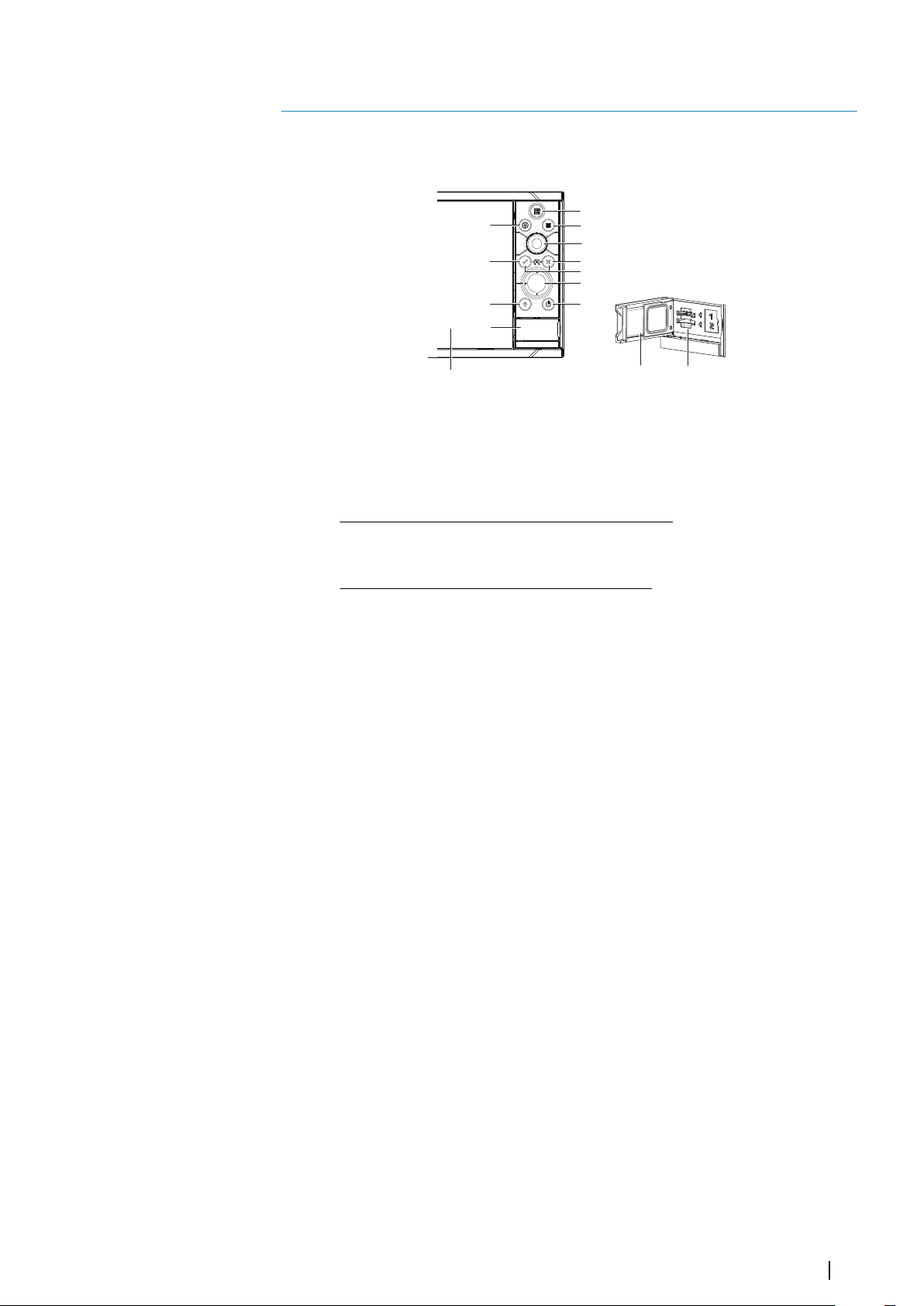
Front controls
1 Touch screen
2 Pages/Home - press to open the Home page for page selection and setup
options
3 WheelKey - user configurable key, refer to "Configuring the WheelKey" on page 20.
Default without an autopilot connected to the system:
• Short press: toggles between panels on split screen
• Long press: maximizes active panel on split screen
Default with an autopilot connected to the system:
• Short press: opens the autopilot controller and puts the autopilot in standby
mode
• Long press: toggles between panels on split screen
4 Menu key - press to display the active panel's menu
5 Rotary knob - turn to zoom or scroll the menu, press to select an option
6 Enter key - press to select an option or to save settings
7 Exit key - press to exit a dialog, return to previous menu level, and clear the cursor
from the panel
8 MOB - press simultaneously the Enter and Exit keys to create a MOB at the
vessel's position
9 Arrow keys - press to activate the cursor or to move the cursor
Menu operation: press to navigate through menu items and to adjust a value
10 Mark key - press to place waypoint at vessel position or at cursor position when
cursor is active
11 Power key - press and hold to turn the unit ON/OFF
Press once to display the System Controls dialog, additional presses to toggle
through three default dimming levels
12 Card reader door
13 Dual card reader slots
Introduction | Zeus3 Operator Manual
11
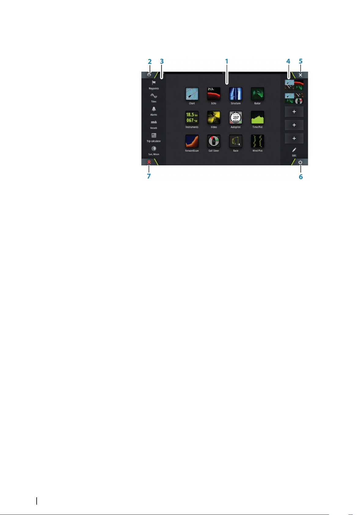
The Home page
1 Applications
Select a button to display the application as a full page panel.
Press and hold a button to display pre-configured split page options for the
application.
2 Settings button
Select to access Settings dialogs.
3 Tools
Select a button to access dialogs used for carrying out a task, or for browsing
stored information.
4 Favorites
Select a button to display the panel combination.
Press and hold a favorite button to enter edit mode for the Favorites panel.
5 Close button
Select to exit the Home page and return to the previous active page.
6 Power button
Select to power off the unit.
7 Man Over Board (MOB) button
Select to save a Man Over Board (MOB) waypoint at the current vessel position.
12
Introduction | Zeus3 Operator Manual
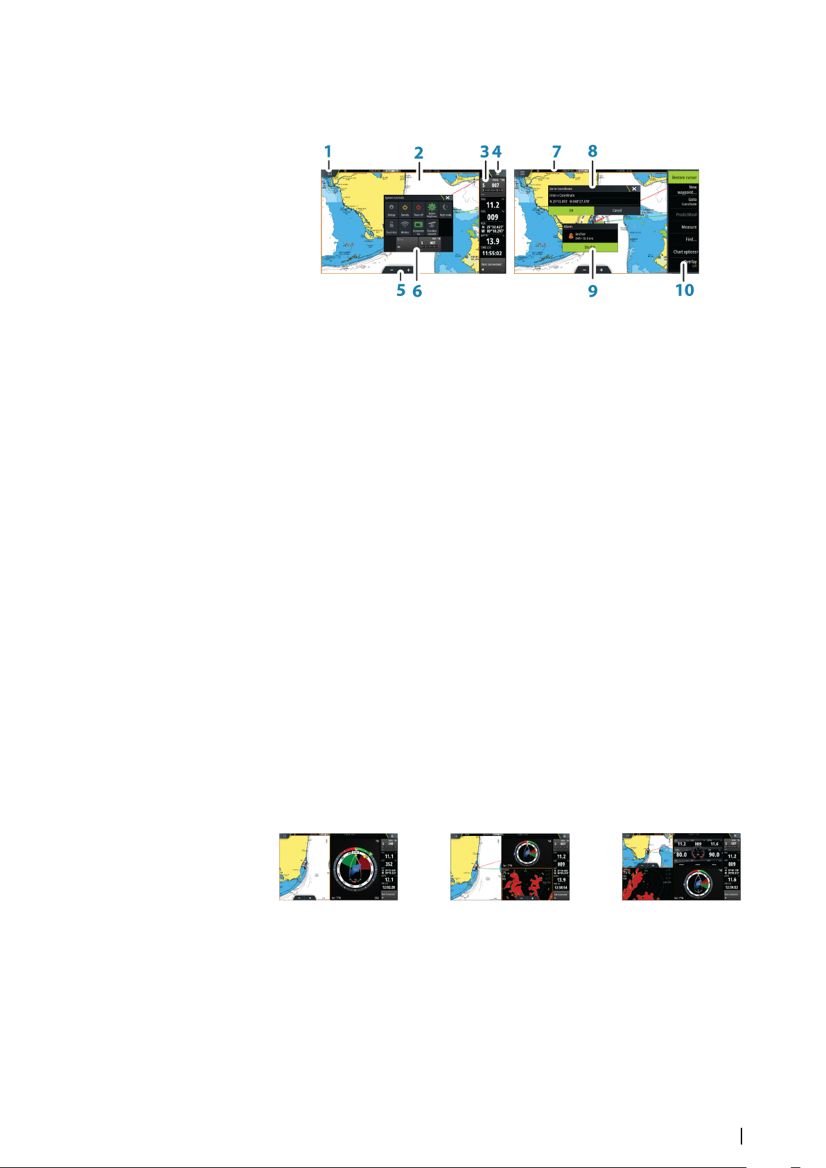
Application pages
Each application connected to the system is presented on panels. The application can be
presented as a full page, or in combination with other panels in a multiple panel page.
All application pages are accessed from the Home page.
1 Home button
2 Application panel
3 Instrument bar
Navigation and sensor information. The bar can be turned off and it can be
configured by the user.
4 Menu button
5 Zoom buttons
6 System controls dialog
Quick access to basic system settings.
Display the dialog by a short press on the Power key or by swiping down from top
of the screen.
7 Status bar
8 Dialog
Information to or input from the user.
9 Alarm message
Displayed if dangerous situations or system faults occur.
10 Menu
Panel specific menu.
Split pages
You can have up to 4 panels on each page.
2 panels page
Panel sizes in a split page can be adjusted from the System Controls dialog.
3 panels page
4 panels page
Pre-configured split pages
Each full screen application has several pre-configured split pages, featuring the selected
application combined with each of the other panels.
Note: The number of pre-configured split pages cannot be changed, and the pages
Ú
cannot be customized or deleted.
Access a pre-configured split page by pressing and holding the main panel button.
Introduction | Zeus3 Operator Manual
13
Favorite pages
All preconfigured favorite pages can be modified and deleted, and you can create your own.
You can have a total of 12 favorite pages.
For more information, refer to "Adding new favorite pages" on page 21.
Integration of 3rd party devices
Several 3rd party devices can be connected to the Zeus³. The applications are displayed on
separate panels or integrated with other panels.
A device connected to the NMEA 2000 network should automatically be identified by the
system. If not, enable the feature from the advanced option in the System settings dialog.
The 3rd party device is operated by using menus and dialogs as on other panels.
This manual does not include specific operation instructions for any 3rd party device. For
features and functionality, refer to the documentation included with the 3rd party device.
FUSION-Link integration
FUSION-Link devices connected to the NMEA 2000 network can be controlled from the Zeus³
system.
The FUSION-Link devices appear as additional sources when using the audio function. No
additional icons are available.
Refer to "Audio" on page 112 for more information.
FLIR camera integration
If a FLIR M-series camera is available on the Ethernet network, you can display the video and
control the camera from the Zeus³.
The FLIR camera is controlled from the Video panel, and no additional icons appear on the
Home page.
Refer to "Video" on page 123 for more information.
BEP CZone integration
The Zeus³ integrates with BEP’s CZone system used for controlling and monitoring a
distributed power system on your vessel.
The CZone icon is available in the Tools panel on the Home page when a CZone system is
available on the network.
A separate manual is provided with your CZone system. Refer to this documentation and to
the Zeus³ Installation manual for how to install and configure the CZone system.
CZone dashboard
When the CZone is installed and configured, an additional CZone dashboard is added to the
Instruments panels.
You switch between a panel’s dashboards by selecting the left and right arrow symbols or by
selecting the dashboard from the menu.
Editing a CZone dashboard
You can customize a CZone dashboard by changing the data for each of the gauges.
Available editing options depend on the type of gauge and which data sources that are
connected to your system.
For more information, refer to "Instrument panels" on page 111.
14
Introduction | Zeus3 Operator Manual

H5000 integration
The unit integrates with B&G’s H5000 Instrument and Autopilot system.
The H5000 icon will be available in the Tools panel on the Home page when an H5000
system is available on the network.
Separate documentation is provided with the H5000 system. Refer to this documentation for
how to install and configure the H5000 system.
Remote controllers
You can connect a remote controller to the network and remotely control the unit. To find
out which remote controllers can be used, refer to the product web page at:
www.bandg.com.
A separate manual is included with the remote controller.
Introduction | Zeus3 Operator Manual
15
Basic operation
2
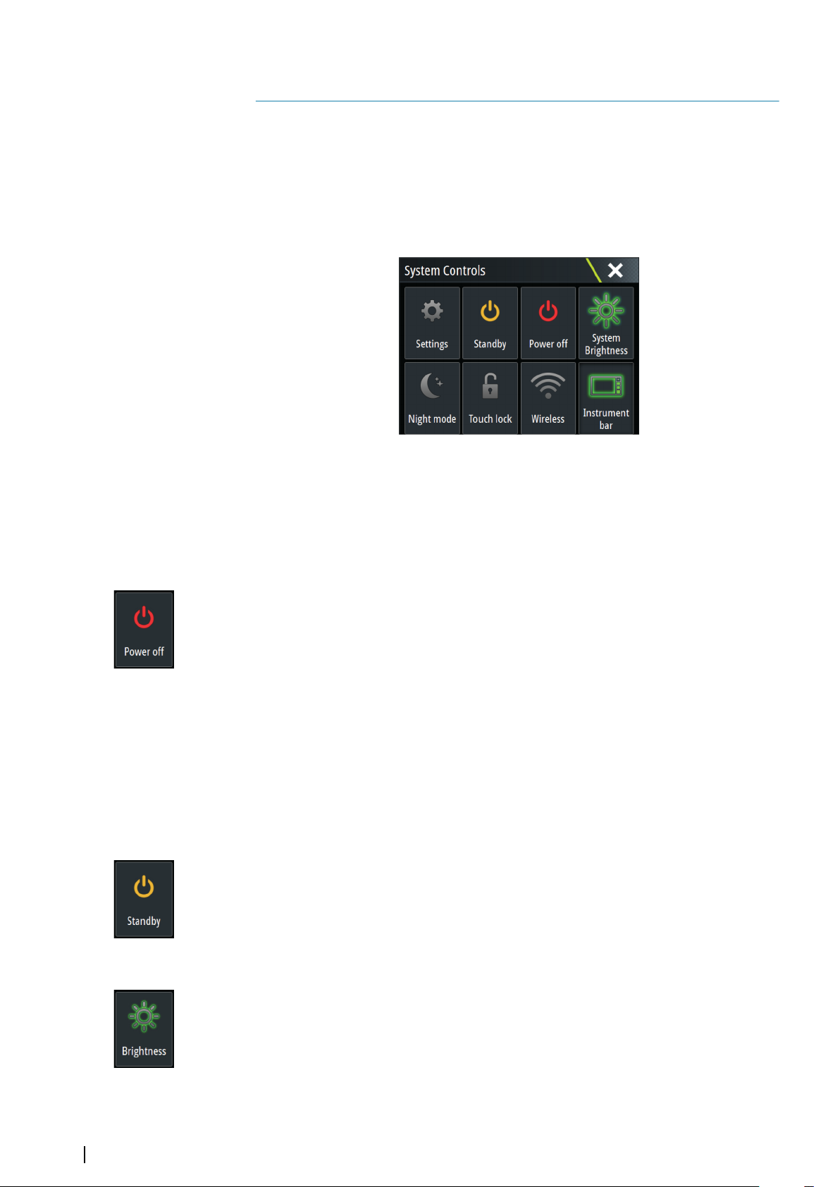
System Controls dialog
The System Controls dialog provides quick access to basic system settings. You display the
dialog by making a short press on the Power key or by swiping down from the top of the
screen.
The icons displayed on the dialog can vary. For example, the adjust splits option is only
available if you are viewing a split page when you open the System Controls dialog.
Activating functions
Select the icon of the function you want to set or toggle on or off. For those functions that
toggle on and off, a highlighted icon indicates the function is activated, as shown in the
Instrument bar icon above.
Turning the system on and off
You turn the system off by pressing the Power key, or by selecting the Power option on the
Home page or in the System Controls dialog.
If the Power key is released before the shut-down is completed, the power off process is
cancelled.
Note: If the unit is configured as a slave, you cannot power off the unit by the Power
Ú
key, and the System Controls dialog does not display the power off option.
First time startup
When the unit is started for the first time, or after a factory default, the unit displays a setup
wizard. Respond to the setup wizard prompts to select some fundamental setup options.
You can perform further setup using the system settings option and later change settings
made with the setup wizard.
Standby mode
In Standby mode, the backlight for screen and keys are turned off to save power. The system
continues to run in the background.
You select Standby mode from the System Controls dialog.
Display illumination
Brightness
The display backlighting can be adjusted at any time from the System Controls dialog.
You can also cycle the preset backlight levels by short presses on the Power key.
16
Night mode
The night mode option optimizes the color palette and backlight for low light conditions.
Note: Details on the chart may be less visible when the Night mode is selected!
Ú
Basic operation | Zeus3 Operator Manual
Wireless
Provides wireless connection options dependent on the status of the wireless. For example,
connect to a hotspot or change to access point. For option explanations refer to "Wireless
connection" on page 103.
Locking the touchscreen
You can temporarily lock a touchscreen to prevent accidental operation of the system. Lock
the touchscreen when large amounts of water are on the screen, for example, in heavy seas
and weather. This feature is also useful when cleaning the screen while the unit is turned on.
When the touch lock is active you can only operate the unit from the keys.
You lock the touchscreen from the System Controls dialog.
You remove the lock function by a short press on the Power key.
Instrument bar
Toggles the Instrument bar on/off for the current page only.
Touchscreen operation
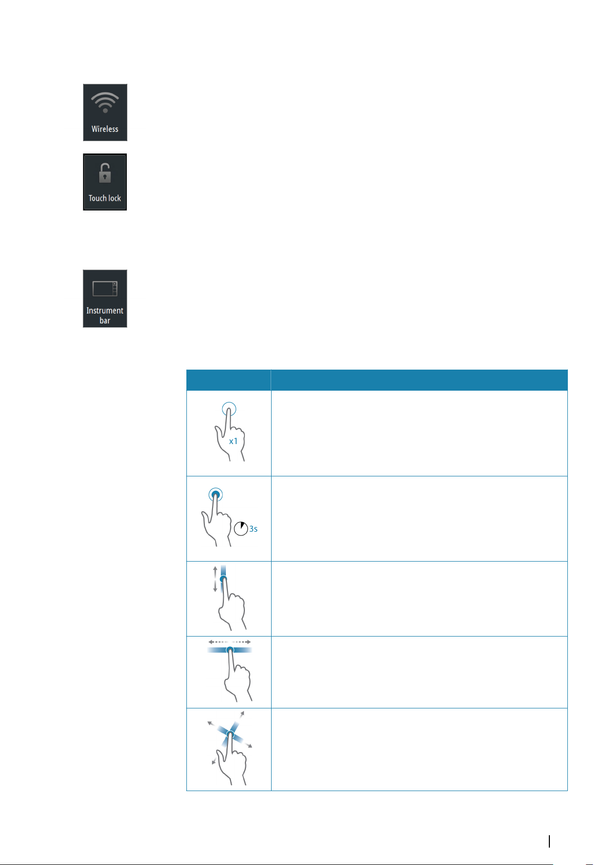
Basic touchscreen operation on the different panels is shown in the table below.
The panel sections in this manual have more information about panel specific touchscreen
operation.
Icon Description
Tap to:
• Activate a panel on a multi-panel page
• Position the cursor on a panel
• Select a menu and a dialog item
• Toggle a checkbox option on or off
• Show basic information for a selected item
Press and hold:
• On any panel with a cursor to either activate the cursor assist feature
or open the menu. Refer to "Customizing the long press feature" on page 20
• On the Instrument panel to open the Choose data dialog
• On a panel button to see available split screen options
• On a favorite button to enter edit mode
Scroll through a list of available options without activating any option.
Flick to quickly scroll through e.g. the waypoint list. Tap the screen to
stop the scrolling.
Pan to position a chart or Echosounder image on the panel.
Basic operation | Zeus3 Operator Manual
17
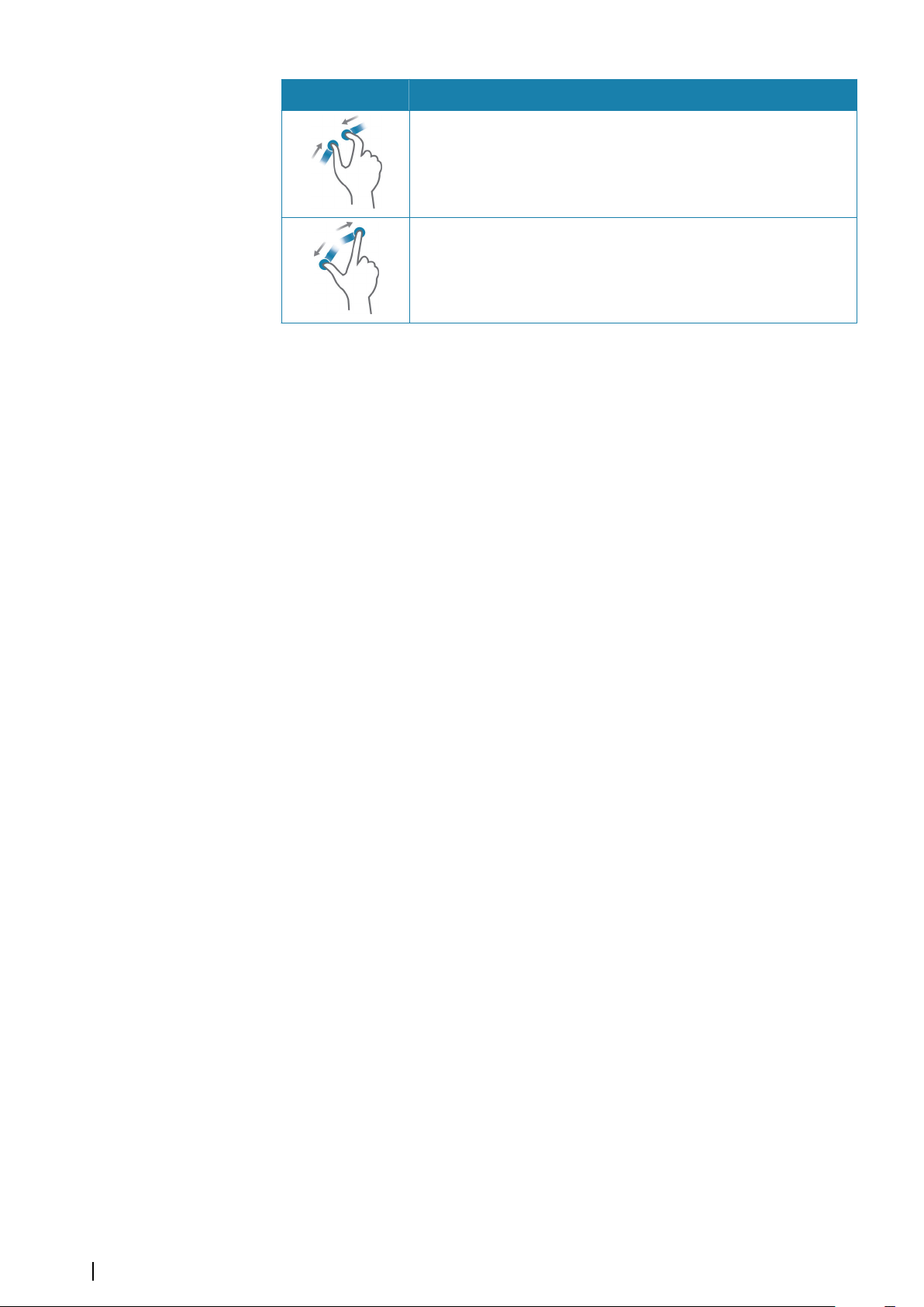
Icon Description
Pinch to zoom out on the chart or on an image.
Spread to zoom in on the chart or on an image.
Using menus and dialogs
Menus
You display a page menu by selecting the MENU button in the upper right corner of the
page.
• Activate a menu item and toggle on/off an option by selecting it
• Adjust a slide bar value by either:
- dragging the slide bar
- selecting the + or - icons
You can also operate the menus by using the rotary knob:
• Turn the knob to scroll through menu items
• Press the knob to select a highlighted item
• Turn the knob to adjust the value of a selected item
Select the Back menu option or the X key to return to the previous menu level, and then
exit.
The status of the cursor (active vs. inactive) changes the menu options.
Dialog boxes
You select entry fields and keys in a dialog box by tapping the screen or by using the rotary
knob.
Numeric and alphanumeric keyboards are automatically displayed when required for
entering user information in dialogs. You operate the keyboard by selecting the virtual keys,
and you confirm your entry by selecting the virtual Enter key or by pressing the rotary knob.
A dialog is closed by saving or cancelling the entry.
A dialog can also be closed by selecting the X in the dialog's upper right corner or by
pressing the X key.
Selecting pages and panels
Selecting a page
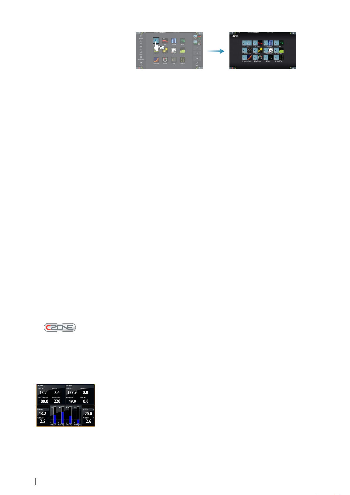
• Select a full page panel by selecting the relevant application button on the Home page
• Select a favorite page by selecting the relevant favorite button
• Select a predefined split panel by pressing and holding the relevant application icon
18
Select active panel
In a multiple panel page, only one panel can be active at a time. The active panel is outlined
with a border.
You can only access the page menu of an active panel.
You activate a panel by tapping it.
Displaying the Favorites panel as a pop-up on a page
You can display the Favorites panel as a pop-up on any page by pressing and holding the
Home key.
Basic operation | Zeus3 Operator Manual

Select a favorites page in the pop-up to display it. The panel will switch to the selected
favorite after 3 seconds.
Creating a Man Overboard waypoint
If an emergency situation should occur, you can create a Man Overboard (MOB) waypoint at
the vessel’s current position by selecting the MOB button on the Home page.
You can also save a Man Overboard (MOB) waypoint at the vessel’s current position by
pressing the Enter and Exit keys simultaneously. Simultaneous pressing the Enter and Exit
keys creates a MOB at the vessel's location
When you activate the MOB function the following actions are automatically performed:
• a MOB waypoint is created at the vessel’s position
• the display switches to a zoomed chart panel, centered on the vessel's position
• the system displays navigation information back to the MOB waypoint
Multiple MOB waypoints are saved by repeatedly pressing the MOB buttons. The vessel
continues to show navigation information to the initial MOB waypoint. Navigation to
subsequent MOB waypoints needs to be done manually.
Cancel navigation to MOB
The system continues to display navigational information towards the MOB waypoint until
you cancel the navigation from the menu.
Delete a MOB waypoint
1. Select the MOB waypoint to activate it
2. Tap the MOB waypoint's pop-up or press the Enter key or the rotary knob to display the
MOB waypoint dialog
3. Select the delete option in the dialog.
A MOB waypoint can also be deleted from the menu when it is activated.
Screen capture
Simultaneously press the Home and Power keys to take a screen capture. Screen captures
are saved to internal memory.
You need to turn on the Screen capture option in the System Settings dialog to be able to
take a screenshot on a touch screen. When the function is activated, you can take a
screenshot on a touch screen by double-selecting the title bar of an open dialog, or by
double-selecting the status bar if no dialog is open.
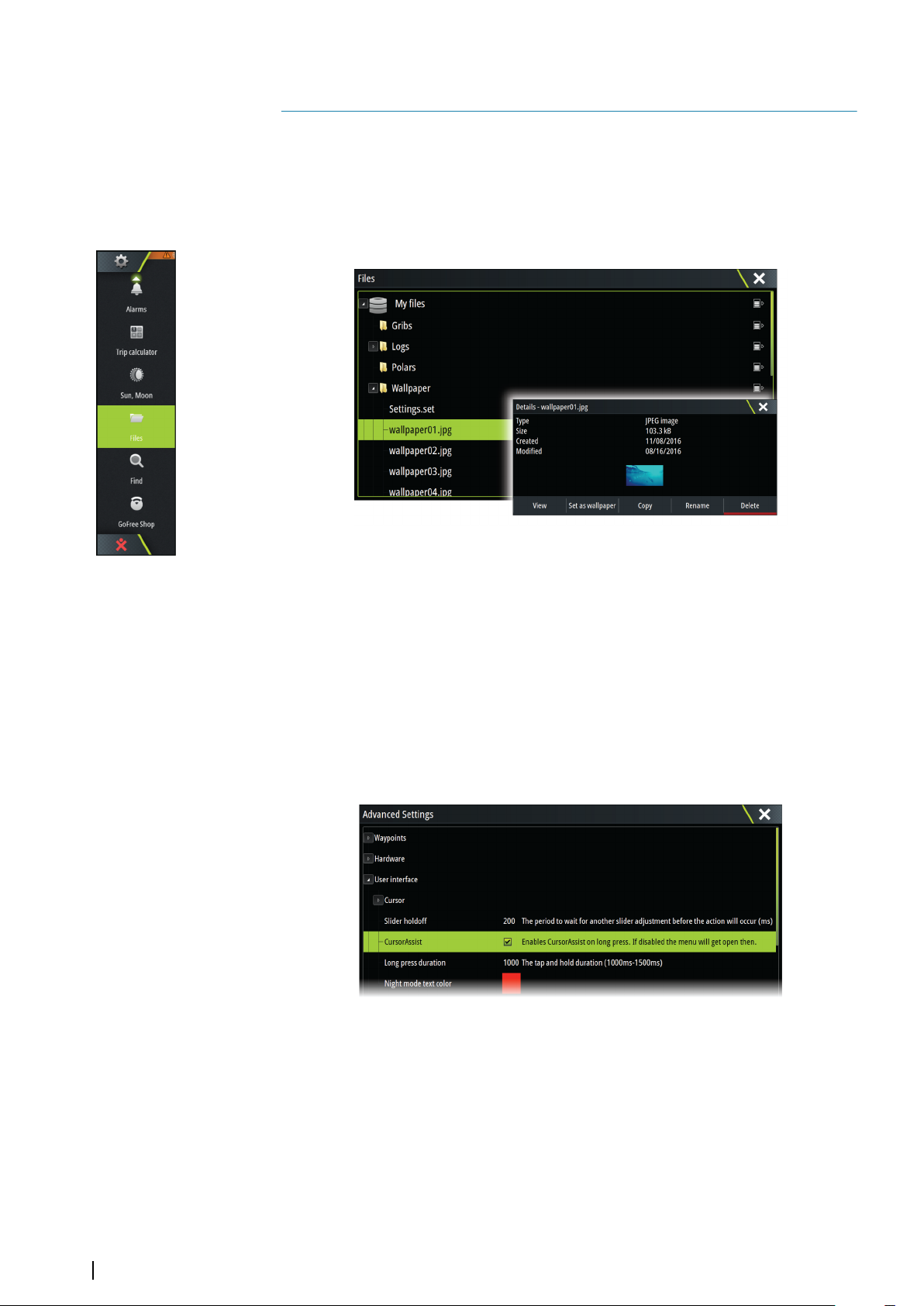
To view files, refer to "Files" on page 127.
Basic operation | Zeus3 Operator Manual
19
Customizing your system
3
Customizing the Home page wallpaper
The Home page's wallpaper can be customized. You can select one of the pictures included
with the system, or you can use your own picture in .jpg or .png format.
The images can be available on any location that can be seen in the files browser. When a
picture is chosen as the wallpaper, it is automatically copied to the Wallpaper folder.
Configuring the WheelKey
You can define what happens with a short or long press of the WheelKey on the front of the
unit.
To configure the Wheel key, select Configure WheelKey on the System Setting dialog.
Select the Short press option or Long press option in the WHEELKEY CONFIGURATION
dialog and then an option from the list displayed.
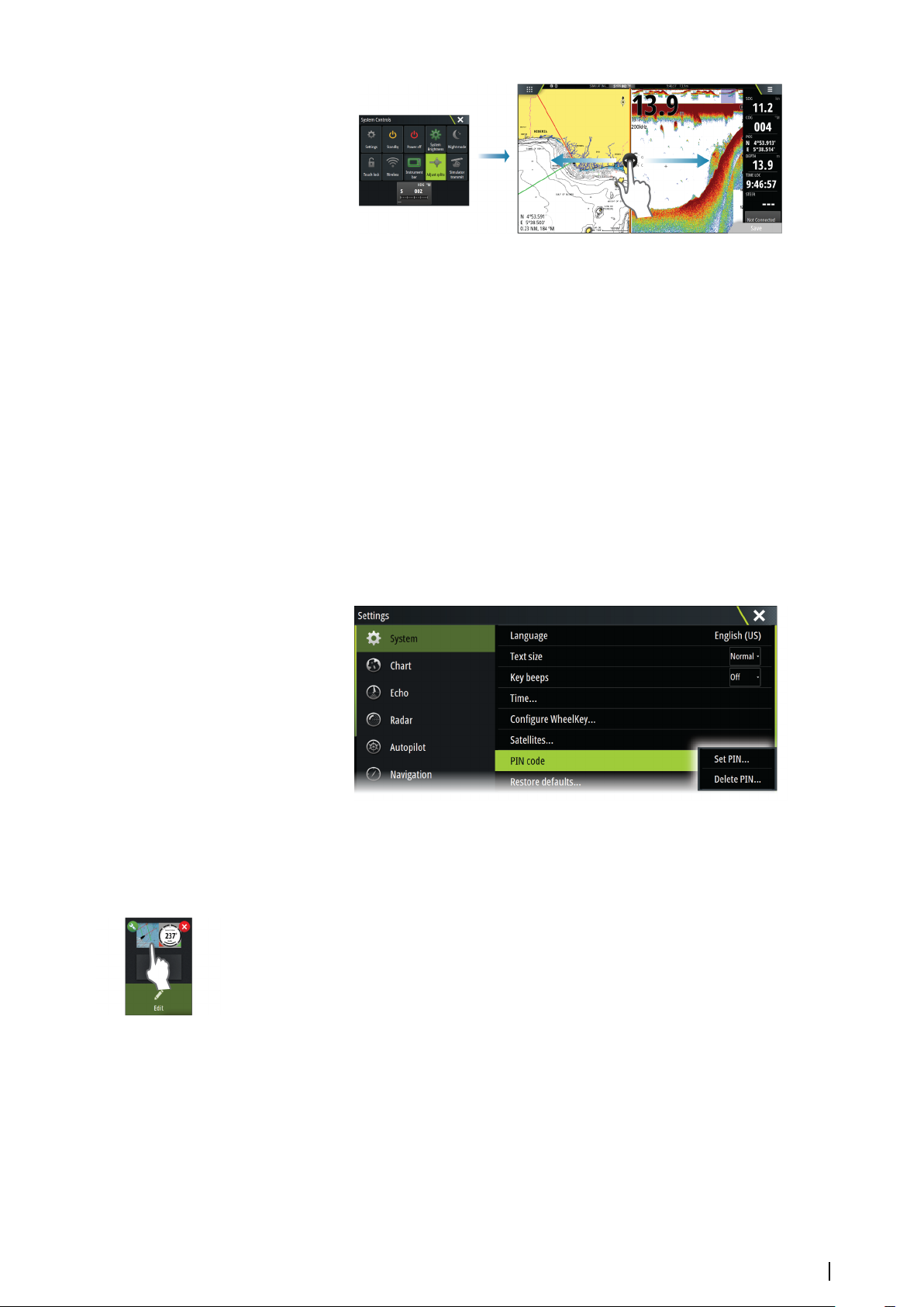
Customizing the long press feature
Use the Advanced settings dialog to specify if the long press on the panel opens the menu
or displays the cursor assist feature on the panel.
Adjusting panel size
You can change the panel size for an active split page. The panel size can be adjusted for
both favorite pages and for predefined split pages.
1. Activate the System Controls dialog
2. Select the adjust splits option in the dialog
3. Adjust the panel size by dragging the adjustment icon
4. Confirm your changes by tapping one of the panels, by pressing the rotary knob or the
Enter key.
20
Customizing your system | Zeus3 Operator Manual
The changes are saved to the active favorite or split page.
Password protection
You can set a PIN code to prevent unauthorized access to your system settings.
Note: We recommend you record the PIN code (password) and store it in a safe place if you
use this feature.
When you establish password protection, the PIN code must be entered when any of the
following are selected. After the correct PIN code is entered, all of them can be accessed
without re-entering the PIN code.
• Settings, activated from the Tools panel or System Controls dialog
• Alarms, activated from the Tools panel
• Files, activated from the Tools panel
• GoFree Shop, activated from the Tools panel
• Settings, activated from the Chart menu under Chart Options
You set and remove password protection from the system Settings dialog.
Adding new favorite pages
1. Select the New icon in the favorite panel on the Home page to open the page editor
dialog
2. Drag and drop page icons to set up a new page
3. Change the panel arrangement (only possible for 2 or 3 panels), if required
4. Save the page layout.
The system displays the new favorite page, and the new page is included in the list of
favorite pages on the Home page.
Customizing your system | Zeus3 Operator Manual
21
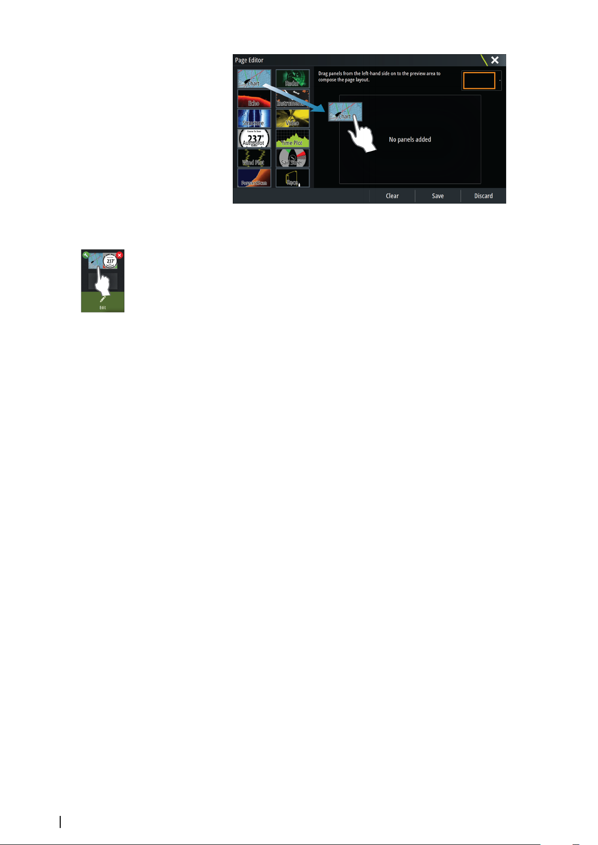
Edit favorite pages
1. Select the edit icon in the Favorite panel:
- Select the X icon on a favorite icon to remove the page
- Select the tool icon on a favorite icon to display the page editor dialog
2. Add or remove panels in the page editor dialog
3. Save or discard your changes to leave the favorite edit mode.
Setting the appearance of the Instrument bar
Data sources connected to the system can be viewed in the Instrument bar.
You can configure the Instrument bar to display either one or two bars. If you specify to
display two bars you can set it to alternate the bars automatically. You can specify the
information displayed in the instrument bars.
You can turn the Instrument bar off from the System controls dialog.
Note: This only turns the Instrument bar off for the current page.
Ú
Turning the Instrument bar on/off
1. Activate the System controls dialog
2. Deactivate/activate the instrument bar icon to toggle the bar on and off.
Edit the content of the Instrument bar
1. Activate the Instrument bar by selecting it
2. Select the MENU button to open the menu
3. Select Edit to change an instrument gauge followed by the gauge you want to change
4. Select the content you want to display from the Choose Data dialog
22
Note: You can configure Bar 1 for the active page or for all pages except those that have
Ú
a local configuration. Bar 2 can only be configured for the active page.
5. Select Menu and then Finish editing to save your changes.
Customizing your system | Zeus3 Operator Manual
4
Charts
The chart function displays your vessel’s position relative to land and other chart objects. On
the chart panel you can plan and navigate routes, place waypoints, and display AIS targets.
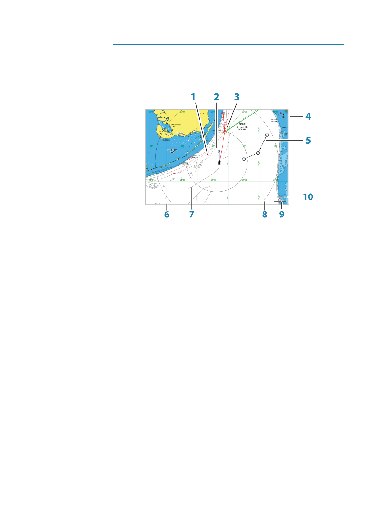
The Chart panel
1 MOB (Man Over Board) mark
2 Vessel with extension line (extension line is optional)
3 Waypoint with Laylines*
4 North indicator
5 Route*
6 Grid lines*
7 Track*
8 Range rings*
9 Chart range scale
10 Range rings interval (only displayed when Range rings are turned on)
* Optional chart items. You turn the optional chart items on/off individually from the Chart
settings dialog.
Chart data
The system is delivered with different embedded cartography depending on region.
All units support Insight charts from Navico including Insight Genesis. The system also
supports charts from Navionics and C-MAP as well as content created by a variety of third
party mapping providers in the AT5 format. For a full selection of available charts, visit
www.gofreeshop.com, www.c-map.com, or www.navionics.com.
Note: In this manual, all possible chart menu options are described. These options vary
Ú
depending on the chart you are using.
Charts on chart cards are shared over the Ethernet network, so only one chart card per vessel
is required.
Note: The system does not automatically switch to embedded cartography if the chart
Ú
card is removed. A low-resolution chart will be displayed until you re-insert the card or
manually switch back to the embedded cartography.
Charts | Zeus3 Operator Manual
23
Showing dual chart types
If you have different chart types available - embedded, in the card slot, or on the Ethernet
network - you can show two different chart types simultaneously on a page with two chart
panels.
You can select a dual chart panel by pressing and holding the Chart application button on
the Home page, or by creating a favorite page with two chart panels.
Selecting chart type
You specify the chart type in the Chart panel by selecting one of the available chart types in
the chart source menu option.
If you have a multiple Chart panel, the chart type is set individually for each chart panel.
Activate one of the chart panels, and then select one of the available chart types in the chart
source menu option. Repeat the process for the second chart panel, and select an alternative
chart type for this panel.
If you have identical charts available - built in, in the card slot or on the Ethernet network the system automatically selects the chart with most chart details for your displayed region.
Panning the chart
You can move the chart in any direction by dragging your finger on the screen.
Select the Clear cursor menu option or press the X key to remove the cursor and cursor
window from the panel. This also centers the chart to the vessel position.
Chart scale
You zoom in and out on the chart by using the zoom panel icons, the rotary knob, or by
using 2 fingers to pinch (zoom out) and spread (zoom in).
Chart range scale and range rings interval (when turned on) are shown in the lower right
corner of the chart panel.
Vessel symbol
When the system has a valid GPS position lock, the vessel symbol indicates vessel position. If
no GPS position is available, the vessel symbol includes a question mark.
Positioning the vessel on the chart panel
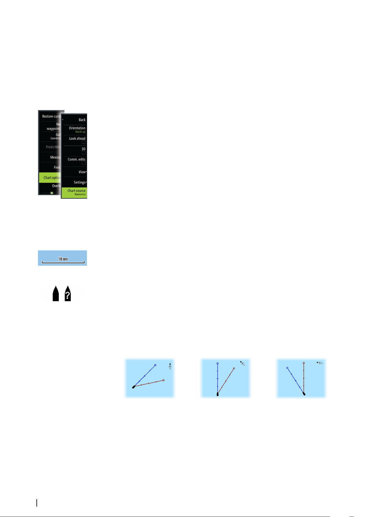
Chart orientation
Several options are available for how the chart is rotated in the panel. The chart orientation
symbol in the panel’s upper right corner indicates the north direction.
North up
Heading up
Course up
24
North up
Displays the chart with north upward.
Heading up
Displays the chart with the vessel’s heading directed upward. Heading information is
received from a compass. If heading is not available, then the COG from the GPS is used.
Course up
Displays the chart with the direction the vessel is ACTUALLY traveling directed upward,
which in some cases is not the direction the vessel is headed.
Charts | Zeus3 Operator Manual
Look ahead
Moves the vessel icon closer to the bottom of the screen so that you can maximize your view
ahead.
Displaying information about chart items
When you select a chart item, a waypoint, a route, or a target, basic information for the
selected item is displayed. Select the chart item's pop-up to display all available information
for that item. You can also activate the detailed information dialog from the menu.
Note: If you are viewing applicable C-MAP charts on your system, you can select marine
Ú
objects to display information about services and available multimedia (photos)
associated with the location or object.
Note: Pop-up information has to be enabled in chart settings to see basic item
Ú
information.
Using the cursor on the chart panel
By default, the cursor is not shown on the chart panel.
When you activate the cursor, the cursor position window is displayed. When the cursor is
active, the chart does not pan or rotate to follow the vessel.
Press the X key or select the Clear cursor menu option to remove the cursor and the cursor
window from the panel. This also centers the chart to the vessel position.
Select the Restore cursor menu option to display the cursor in its previous location. The
Clear cursor and Restore cursor options are useful features for toggling between the
vessel's current location and the cursor position.
GoTo cursor
You can navigate to a selected position on the image by positioning the cursor on the panel,
then using the Goto Cursor option in the menu.
The cursor assist function
Note: The cursor assist function is available if it is enabled. Refer to "Customizing the long press
Ú
feature" on page 20.
The cursor assist function allows for fine tuning and precision placement of the cursor
without covering details with your finger.
Activate the cursor on the panel, then press and hold your finger on the screen to switch the
cursor symbol to a selection circle, appearing above your finger.
Without removing your finger from the screen, drag the selection circle to the desired
position.
When you remove your finger from the screen the cursor reverts to normal cursor operation.
Measuring distance
The cursor can be used to measure the distance between your vessel and a selected position,
or between 2 points on the chart panel.
1. Position the cursor on the point from where you want to measure the distance. Start the
measure function from the menu
Charts | Zeus3 Operator Manual
25
- The measuring icons appear with a line drawn from the vessel center to the cursor
position, and the distance is listed in the cursor information window.
2. You can reposition the measuring points by dragging either icon as long as the
measuring function is active
Note: The bearing is always measured from the grey icon to the blue icon.
Ú
You can also start the measuring function without an active cursor. Both measuring icons are
then initially located at the vessel position. The grey icon follows the vessel as the vessel
moves, while the blue icon remains at the position given when you activated the function.
You terminate the measuring function by selecting the Finish measuring option or by
pressing the X key.
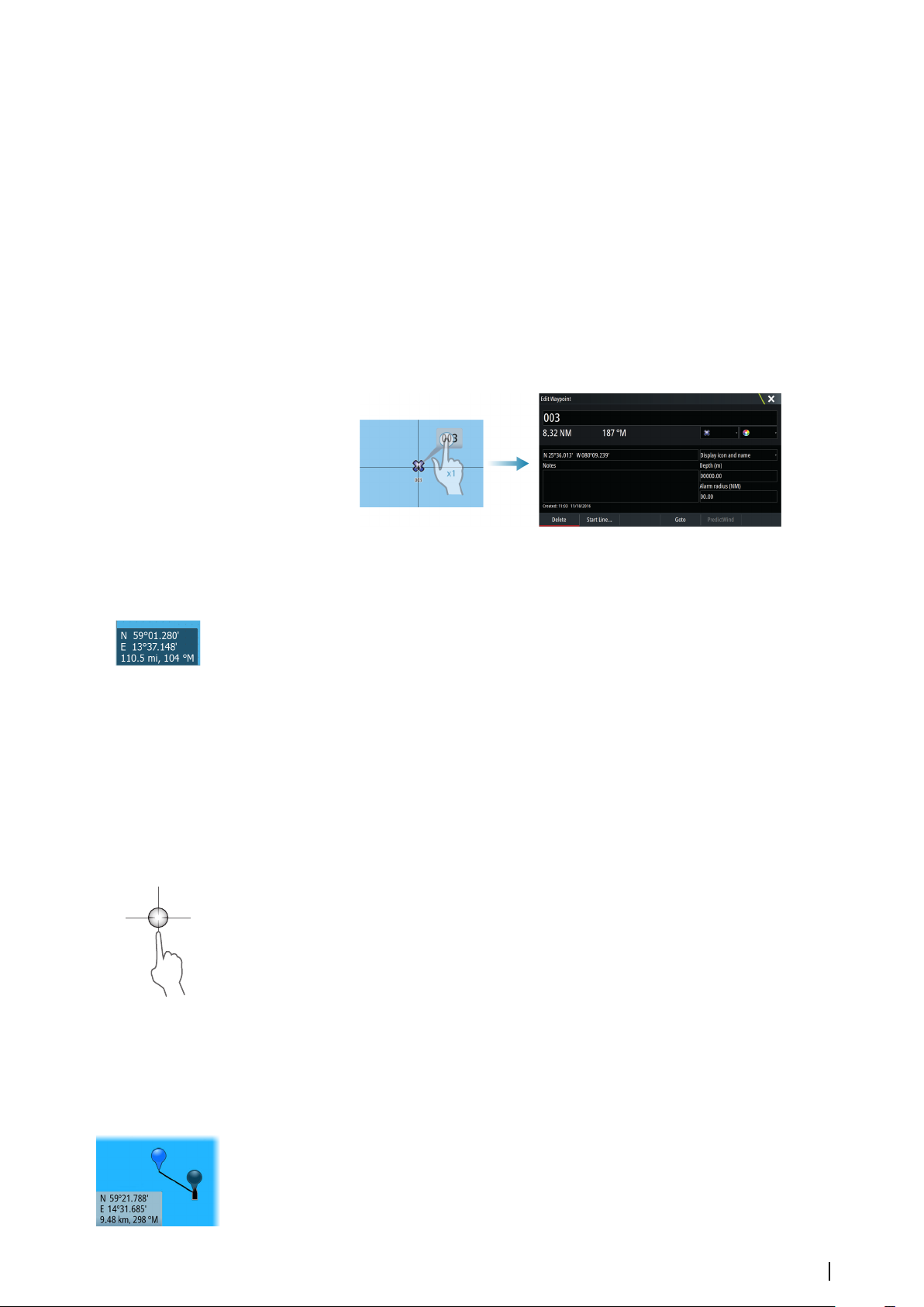
Saving waypoints
A waypoint is saved at the cursor position if active or at the vessel's position if the cursor is
not active on the panel, by doing the following:
• Pressing the rotary knob
• Pressing the Mark key
• Using the new waypoint option in the menu
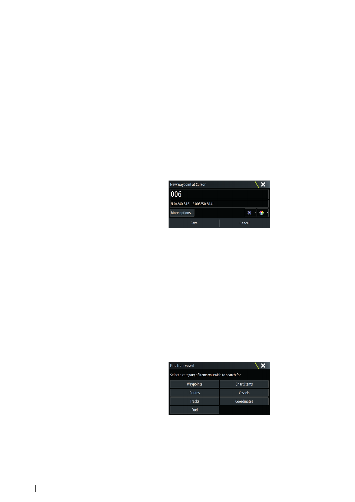
Creating routes
You can create routes as follows on the chart panel.
1. Position the cursor on the chart panel
2. Select New followed by New route in the menu
3. Tap the chart panel to position the first routepoint
4. Continue positioning the remaining routepoints
5. Save the route by selecting the save option in the menu.
Note: For more information, refer to "Waypoints, Routes, and Tracks" on page 37.
Ú
Find objects on chart panels
You can search for other vessels or various chart items from a chart panel.
Activate the cursor on the panel to search from the cursor position. If the cursor is not active,
the system searches for items from the vessel's position.
26
Note: You must have a SIRIUS data package subscription to search for fueling stations
Ú
and an AIS receiver connected to search for vessels.
3D charts
The 3D option provides a three dimensional graphical view of land and sea contours.
Charts | Zeus3 Operator Manual

Note: All chart types work in 3D mode, but without 3D cartography for the appropriate
Ú
area the chart appears flat.
When the 3D chart option is selected, the Pan and the Rotate icons appear on the chart
panel.
Panning the 3D chart
You can move the chart in any direction by selecting the Pan icon and then panning in the
desired direction.
Select the Return to vessel menu option to stop panning, and to center the chart to vessel
position.
Controlling the view angle
You can control the view angle by selecting the Rotate icon and then panning the chart
panel.
• To change the direction you are viewing, pan horizontally
• To change the tilt angle of the view, pan vertically
Note: When centered on the vessel position, only the tilt angle can be adjusted. The
Ú
view direction is controlled by the chart orientation setting. See "Positioning the vessel on the
chart panel" on page 24.
Zooming a 3D chart
You zoom in and out on a 3D chart by using the zoom panel icons or the rotary knob.
Chart overlay
Radar, structure, SonarChart Live (Navionics charts only) and weather data can be displayed
as overlay on your chart panel.
When an overlay is selected, the chart menu expands to include basic menu functions for the
selected overlay.
Radar, structure and weather functions are described in separate sections in this manual. For
more information about SonarChart Live, see section "SonarChart Live" on page 30.
PredictWind weather and routing
For information about PredictWind weather and PredictWind routing, refer to "PredictWind" on
page 55.
Insight and C-MAP charts
All possible menu options for Insight and C-MAP charts are described below. The features
and menu options available can vary depending on the charts you use. This section shows
menus from an Insight chart.
Note: A menu option is greyed out if it is not available on the chart displayed. For
Ú
example, raster charts are not available with Insight, so the Raster charts menu option is
greyed out when Insight charts are displayed.
Insight and C-MAP tides and currents
The system can display Insight and C-MAP tides and currents. With this information it is
possible to predict the time, level, direction and strength of currents and tides. This is an
important tool when considering planning and navigation of a trip.
In large zoom ranges the tides and currents are displayed as a square icon including the
letter T (Tides) or C (Current). When you select one of the icons, tidal or current information
for that location are displayed.
Dynamic current data can be viewed by zooming inside a 1-nautical mile zoom range. At
that range, the Current icon changes to an animated dynamic icon that shows the speed and
direction of the current. Dynamic icons are colored in black (greater than 6 knots), red
(greater than 2 knots and less than or equal to 6 knots), yellow (greater than 1 knot and less
Charts | Zeus3 Operator Manual
27
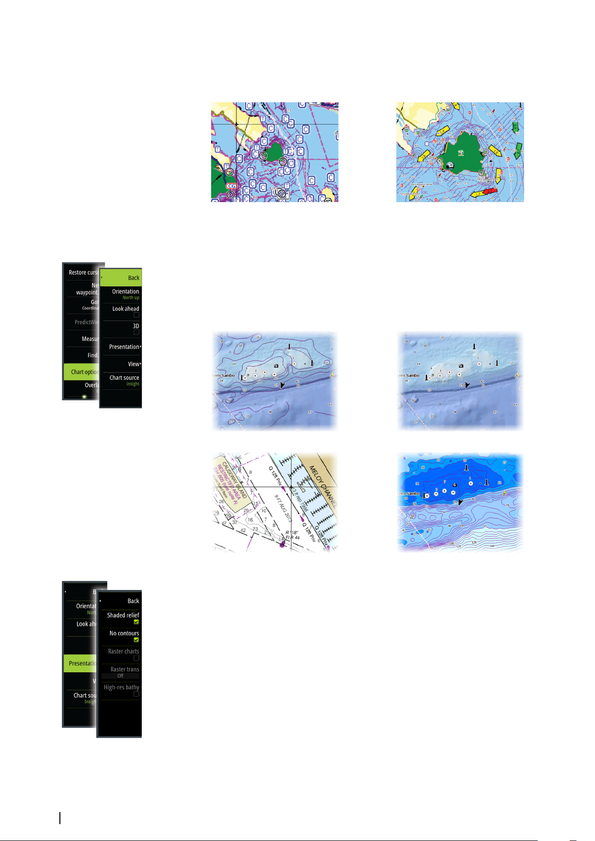
than or equal to 2 knots) or green (equal to or less than 1 knot), depending on the current in
that location.
If there is no current (0 knots) this will be shown as a white, square icon.
Static Current and Tide icons Dynamic Current icons
Insight and C-MAP specific chart options
Orientation, Look ahead, 3D, and change Chart source (previously described in this section)
are common for all chart types.
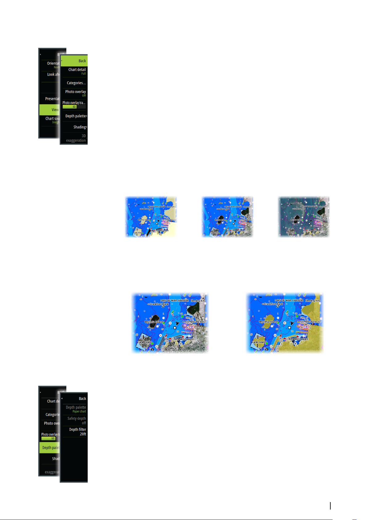
Presentation
The charts can be displayed in different imagery styles.
Shaded relief No contours
Raster imagery
Shaded relief
Shades seabed terrain.
No contours
Removes contour lines from the chart.
Raster charts
Changes the view to that of a traditional paper chart.
Raster transparency
Controls the transparency of raster imagery.
High resolution bathymetry
28
High resolution bathymetry
Enables and disables higher concentration of contour lines.
Charts | Zeus3 Operator Manual
Insight and C-MAP view options
Chart detail
• Full
All available information for the chart in use.
• Medium
Minimum information sufficient for navigation.
• Low
Basic level of information that cannot be removed, and includes information that is
required in all geographic areas. It is not intended to be sufficient for safe navigation.
Insight and C-MAP chart categories
Insight and C-MAP charts include several categories and sub-categories that you can turn
on/off individually depending on which information you want to see.
Photo overlay
Photo overlay enables you to view satellite photo images of an area as an overlay on the
chart. The availability of such photos is limited to certain regions, and cartography versions.
You can view photo overlays in either 2D or 3D modes.
No Photo overlay Photo overlay, land only Full Photo overlay
Photo transparency
The Photo transparency sets the opaqueness of the photo overlay. With minimum
transparency settings the chart details are almost hidden by the photo.
Minimum transparency
Depth palette
Transparency at 80
Controls the Depth palette used on the map.
Paper chart
Changes the appearance of the map to a paper chart style.
Safety depth
Insight and C-MAP charts use different shades of blue to distinguish between shallow (lighter
shades) and deep (darker shades) water. After enabling Safety depth, specify the
desired safety depth limit. The Safety depth sets the limit at which depths will be
drawn without blue shading.
Depth filter
Filters out depth values shallower than the selected depth filter limit.
Charts | Zeus3 Operator Manual
29
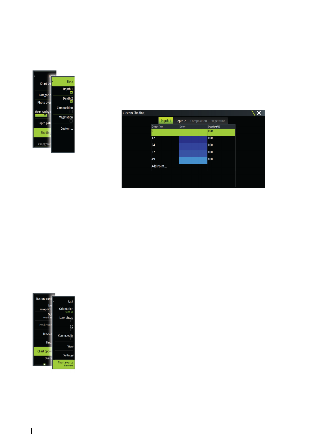
Shading
Shades different areas of the seabed, depending on the selected Shading category.
Note: Composition and Vegetation shading are not applicable to C-MAP charts.
Ú
Depth 1 and Depth 2
Depth presets that shade different depths in different colors.
Custom
You can adjust the depth threshold, color and opacity (transparency) of color shading for
Depth 1 and Depth 2.
3D exaggeration
Graphical settings that are available in 3D mode only. Exaggeration is a multiplier applied to
the drawn height of hills on land, and troughs in water to make them look taller or deeper.
Note: This option is grayed out if the data is not available in the map card inserted.
Ú
Navionics charts
Some Navionics features require the most current data from Navionics. For those features, a
message is displayed stating that the feature is unavailable if you do not have the
appropriate Navionics charts or chart card inserted. For more information on what is required
for these features, refer to www.navionics.com
Navionics specific chart options
Orientation, Look ahead, 3D and change Chart source (previously described in this section)
are common for all chart types.
Community edits
Toggles on the chart layer including Navionics edits. These are user information or edits
uploaded to Navionics Community by users, and made available in Navionics charts.
For more information, refer to Navionics information included with your chart, or to
Navionics website: www.navionics.com.
SonarChart Live
SonarChart Live is a real-time feature where the device creates an overlay of depth contours
based on your own live sonar soundings.
In the Navionics chart menu, select Overlay and then SonarChart Live to display it as an
overlay on the chart.
When you select SonarChart Live overlay the menu expands to display SonarChart Live
Options. Use the options to set the transparency and minimum depth.
30
Charts | Zeus3 Operator Manual
 Loading...