

B&G Zeus2 Glass Helm ZM User Manual
ZM Series Monitors
User Manual
ENGLISH
bandg.com

Preface
!
As Navico is continuously improving this product, we retain the right to make changes to the
product at any time which may not be reected in this version of the manual. Please contact
your nearest distributor if you require any further assistance.
It is the owner’s sole responsibility to install and use the equipment in a manner that will
not cause accidents, personal injury or property damage. The user of this product is solely
responsible for observing safe boating practices.
NAVICO HOLDING AS AND ITS SUBSIDIARIES, BRANCHES AND AFFILIATES DISCLAIM ALL
LIABILITY FOR ANY USE OF THIS PRODUCT IN A WAY THAT MAY CAUSE ACCIDENTS, DAMAGE
OR THAT MAY VIOLATE THE LAW.
Governing Language: This statement, any instruction manuals, user guides and other
information relating to the product (Documentation) may be translated to, or has been
translated from, another language (Translation). In the event of any conict between any
Translation of the Documentation, the English language version of the Documentation will be
the ocial version of the Documentation.
This manual represents the product as at the time of printing. Navico Holding AS and its
subsidiaries, branches and aliates reserve the right to make changes to specications
without notice.
Copyright
Copyright © 2014 Navico Holding AS.
Warranty
The warranty card is supplied as a separate document.
In case of any queries, refer to the brand web site of your display or system: www.bandg.com
Compliance Statements
The B&G series monitors;
• complies with CE under EMC directive 2004/108/EC
• complies with the requirements of level 2 devices of the Radio-communications
(Electromagnetic Compatibility) standard 2008
The relevant Declaration of Conformity is available in the following website under model
documentation section: www.bandg.com.
Warning
The user is cautioned that any changes or modications not expressly approved by the party
responsible for compliance could void the user’s authority to operate the equipment.
Trademarks
• NMEA 2000 is a registered trademark of the National Marine Electronics Association
• B&G, Simrad, StructureScan, Navico, SonicHub, SimNet, Skimmer, InsightHD, Broadband
Radar and Broadband Sonar are trademarks of Navico, registered in the US and other
countries
• The terms HDMI and HDMI High-Denition Multimedia Interface, and the HDMI Logo
are trademarks or registered trademarks of HDMI Licensing LLC in the United States and
other countries
About this manual
This manual is a reference guide for installing and operating the B&G Series monitors.
The manual does not cover basic background information about how equipment such as
radars, echosounders and AIS work.
Important text that requires special attention from the reader is emphasized as follows:
¼ Note: Used to draw the reader’s attention to a comment or some important information.
Warning: Used when it is necessary to warn personnel that they should proceed
carefully to prevent risk of injury and/or damage to equipment/personnel.

Contents
2 Introduction
2 Items included
3 Display installation
3 Cutout template
3 Fixing options
4 Flush mounting the display
6 VESA mounting the display
7 Connecting the display
7 Rear connections
7 Cable retention
8 Connecting power
9 Connecting touch control
9 Serial connection
9 USB connection
9 Connecting NMEA 2000
10 Typical installation
11 Operating the display
11 First time operation
11 Shortcut functions
11 OSD menu
13 Updating the rmware
13 Checking current rmware version
13 Installing an Update
14 Dimensional drawings
15 Troubleshooting tips
16 Cleaning and maintenance
16 Display removal
16 Replacing the gasket
17 Replacing the lters
17 Other maintenance
18 General specications
19 Accessories
Contents | ZM Series User Manual
|
1
1
Introduction
The B&G ZM Series monitors oer a low prole, high brightness solution for displaying video
from a variety of sources. This includes two models; the ZM16”, and ZM19” Touch monitors.
These models are suited for both indoor and outdoor use. Both monitors accept video via
HDMI, DVI-I and composite inputs.
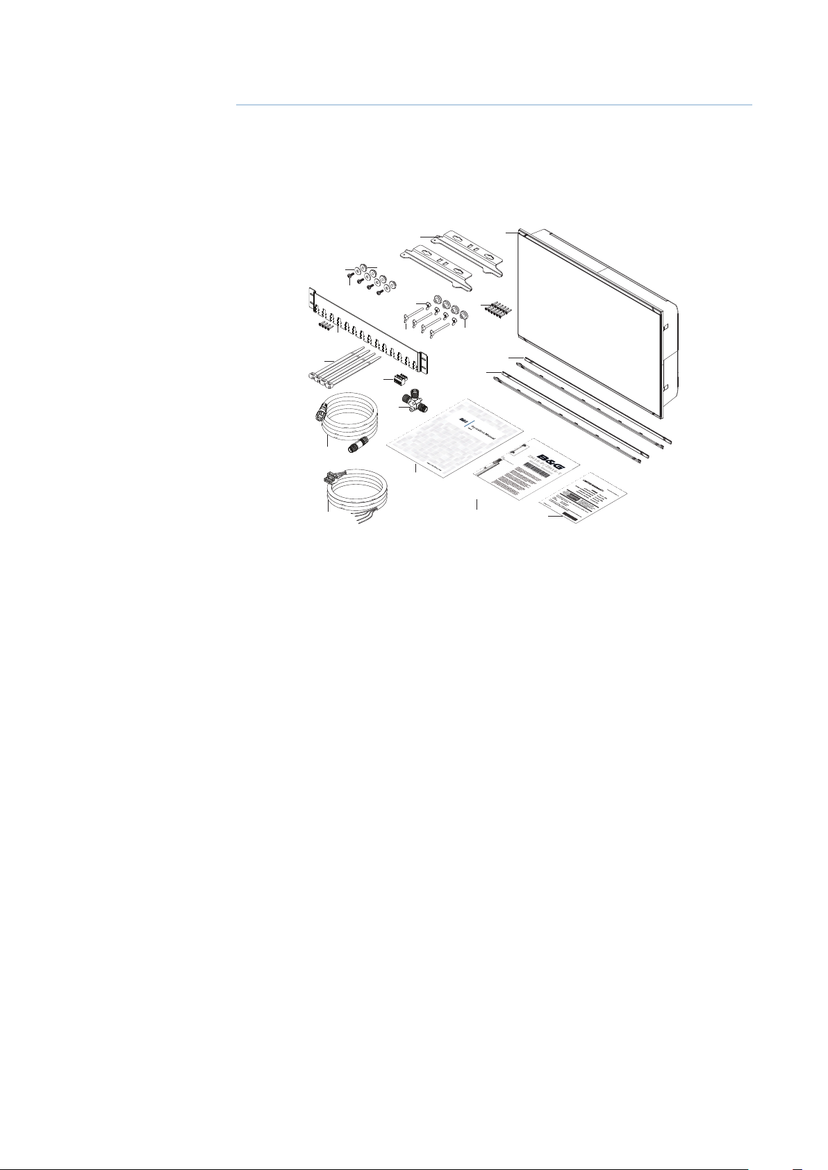
Items included
2
5
3
4
6
1
9
10
11
14
15
1 Monitor
2 Dash mount brackets (x2)
3 Washer, M4, 12mm, SS (x4)
4 Pozi pan head machine screw, M4 x 12mm, SS (x4)
5 Plastic spacer (x4)
6 Wing nut M5 (x4)
7 Wing head machine screw (x4)
8 Plastic stopper - dash mount (x4)
7
12
13
18
8
17
16
19
20
2 |
9 Pozi pan head self-tapping screw 4G x 1/2” (x12)
10 Cable retention bracket with screws 4G x 1/2” (x4)
11 Cable ties (x4)
12 Connector block (serial data)
13 Micro-C tee piece
14 Micro-C cable, 2m (6ft)
15 Power cable with connector
16 Bezel trim, black (x2)
17 Bezel trim, silver (x2)
18 Operator manual
19 Cutout template
20 Warranty card
Introduction | ZM Series User Manual
!
2
Display installation
It is recommended that the unit be powered and connected to a video source to assist in
selecting a suitable mounting location, prior to irreversible modication of the vessel’s helm
station. When planning the display location, the following points should be considered to
ensure safe, comfortable and reliable operation:
• Convenience - the mounting location should be easily accessible to allow operation of the
controls and should enable easy viewing of the display.
• Viewing angle - this LCD has been chosen to give the very best performance, including
viewing angle. However, the contrast and colours seen on all LCD displays vary with
viewing angle, and therefore should be mounted in a way that makes the screen as close to
perpendicular as possible with the expected position of the operator.
• Access - there must be sucient space behind the display to allow cable connections to the
rear connectors, avoiding tight bends in the cable. Also ensure there is sucient access for
tightening wing nuts/screws on the mounting brackets, where used.
• Interference - the selected location should be far enough away from devices that may
cause interference, such as motors, generators and radio transmitters/receivers.
• Magnetic compass - mount the display at least 1 metre (3 ft.) away from a magnetic
compass.
• Environment - to prevent overheating, do not restrict airow at the rear of the display unit;
ensure that there is adequate ventilation, particularly if the display unit is pod-mounted. If
the space behind the display is air conditioned or cooled by a fan, it will help in keeping the
unit’s temperature down. The ZM16/19 displays are designed to operate in indoor/outdoor
environments and in high ambient brightness conditions, however, we recommended
the display not be mounted in a location where it will be exposed to direct sunlight for
prolonged periods. The display should be protected from physical damage and excessive
vibration. Although the display unit is waterproof from the front when installed correctly, it is
good practice to mount it in a protected area away from prolonged and direct exposure to
rain and salt spray.
Warning: Damage incurred to monitor through failure to provide adequate ventilation
could invalidate your warranty. Do not recess device in to an enclosure shared with a heat
source. e.g. engine compartment.
Cutout template
Use the supplied scale template to help mark up the cutout area.
¼ Note: Always check the template dimensions against the physical monitor to ensure
dimensions are correct, prior to making the cutout.
Fixing options
The ZM series monitors can be dash or bracket mounted (using optional VESA adaptor).
When dash mounting, unit should be tted using the rear mounted dash mount brackets,
and bezel screws from the front. Exclusion of the dash mount bracket will greatly increase
strain on bezel screws and adjacent bezel plastics, and is not recommended.
Display installation | ZM Series User Manual
|
3
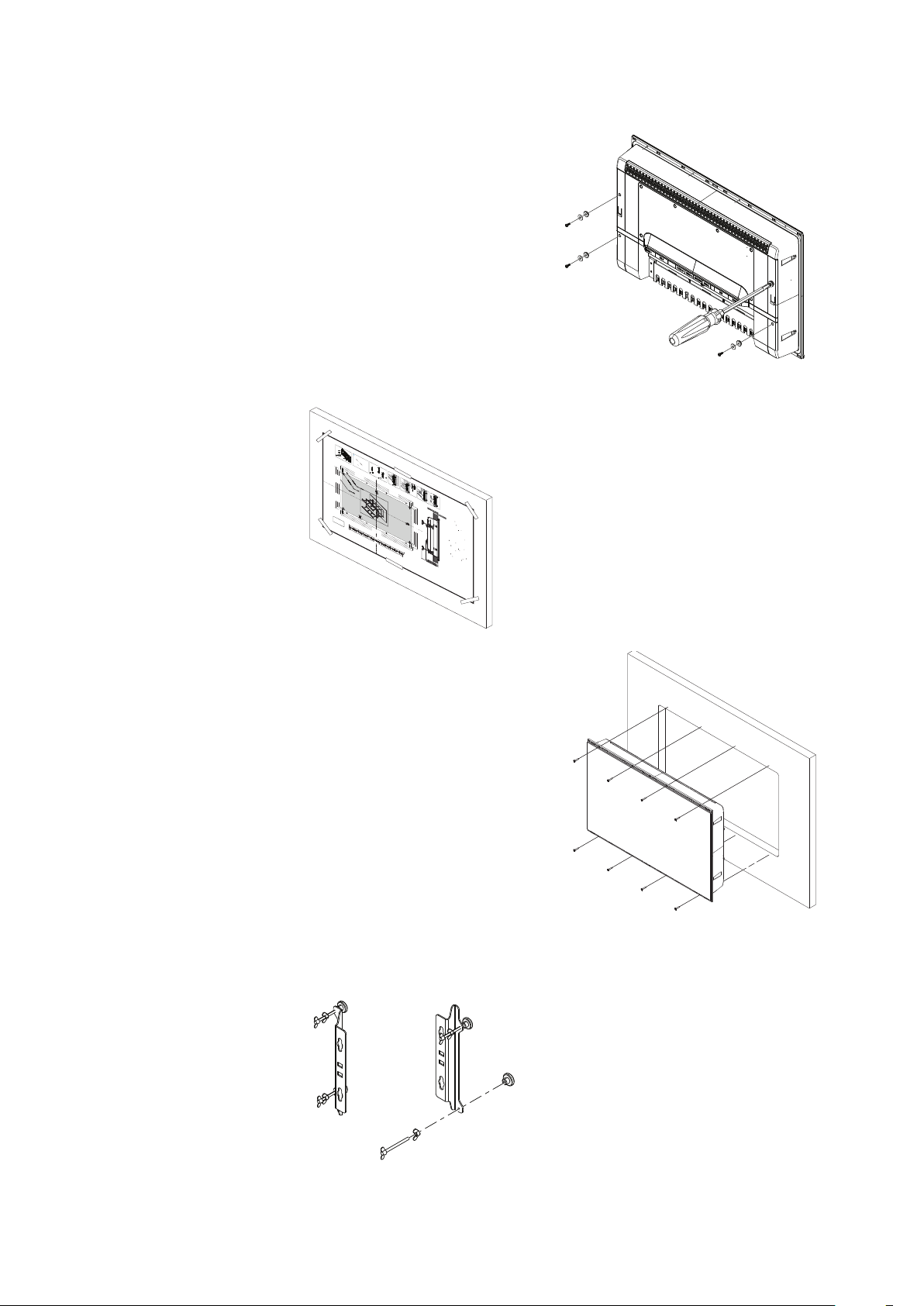
Flush mounting the display
REMOVE SHADED AREA
*988-10455-001*
NOTE:
DO NOT SCALE
PRINT 1:1
IMPORTANT. Do not use this template if it has been rescaled
by copying or prin
ng. If this is not the original, or is a print
from a le, please check the dimension lines below are to
scale before use.
IMPORTANT. Ne pas u
liser ce gabarit s’il a été photocopié ou
imprimé en format réduit ou agrandi. Si ce gabarit n’est ni un
original ni une version imprimée d’un
chier PDF, veuillez
véri er qu’il est à l’échelle avant de l’u
liser.
IMPORTANTE. no usar la plan
lla si hay peligro que la escala
original exacta se ha alterado por copias o procesos de
impresión imprecisos. Si esto no es el original, o un PDF, veri
car que las líneas abajo están a la escala antes de usar.
WICHTIG. Diesen Vordruck nicht verwenden, wenn er durch
Kopieren oder Drucken im Maßstab verändert wurde. Sollte
es nicht das Original oder ein PDF-Ausdruck sein, müssen
untenstehende Zeilen vor erwendung an den rich
gen
Maßstab angepasst werden.
BELANGRIJK. Gebruik deze mal niet indien de schaal is veranderd doordat het is gecopieerd of gedrukt. Indien deze mal
niet het origineel of een print van PDF is, controleer dan of de
onderstaande lijnen de juiste schaal zijn voordat u ze gebruikt.
IMPORTANTE. Não u
lize este gabarito se a escala do mesmo
ver sido alterada por cópia ou impressão. Se não for o
original ou uma cópia impressa de um arquivo PDF, veri que
as linhas abaixo, para acertar a escala antes da u
lização.
VIKTIGT. Använd inte denna mall om den skalats om genom
utskri
eller kopiering. Om de
a inte är originalet eller en
utskri
från en PDF, kontrollera a
linjerna nedan stämmer
med skalan innan det används.
IMPORTANTE. Non u
lizzare questo modello se è stato
ridimensionato copiandolo o stampandolo. Se questo non è
l’originale o la stampa di un le PDF, veri care se le linee che
seguono devono essere dimensionate prima di essere u
lizza-
te.
TÄRKEÄÄ. Älä käytä tätä kaaviota, jos sen mi
akaava on
muu
unut kopio-idessa tai tulostaessa. Jos tämä ei ole alku-
peräinen tai PDF tuloste tarkista rajat mi
akaavasta alla
ennen käy
öä.
注意:请尽量不要使用本安装挖孔尺寸模版图的复印件。
如果使用复印件,则在使用之前请确认其比例一定要与原
件大小必须一致。
중요: 복사나 출력으로 크기가 조정 된 경우 이 템플릿을
사용하지 마십시오. 원본이 아니거나 인쇄물이면,
사용하기 전 아래 치수선의 눈금을 확인 해 주십시오.
注:このテンプレートは印刷やコピーによって縮尺が変
わっていることがありますので使用しないで下さい。テ
ンプレートがオリジナルのものでない場合には、下の寸
法線を使って縮尺を確認してください。
ВНИМАНИЕ: Не используйте эту инструкцию, ес
ли она была изменена в размерах при копирова
нии или распечатке. Если вы используете не ор
игинал, а распечатку из файла, убедитесь в соо
тветствии размеров линейки в нижней части и
нструкции с действительными размерами.
Check dimensions before cutting
12"
300 mm
L
C
L
C
192.5 mm (7.58")
186.0 mm (7.32")
192.5 mm (7.58")
186.0 mm (7.32")
200.0 mm (7.87")
117.5 mm (4.63")
111.0 mm (4.37")
130.0 mm (5.12")130.0 mm (5.12")
117.5 mm (4.63")
111.0 mm (4.37")
200.0 mm (7.87")
385.0 mm (15.16")
372.0 mm (14.65")
400.0 mm (15.75")
235.0 mm (9.25")
222.0 mm (8.74")
260.0 mm (10.24")
ZM-16
Marine Monitor
B&G
X4
1
3
x4
x2
4
CLICK
5
6
7
2
Fit the supplied M4 machine screws, washers,
and plastic spacers to each of the four
threaded ttings on the back case of screen.
Hand tighten only.
Tape appropriate mounting template in place
on dash, and ensure cutout lines are level
relative to a reference point on dash. Drill top
and bottom mounting screw holes using
1.5mm drill bit.
Drill cutout corners with a small pilot drill bit
followed with 13mm drill bit. Complete cutout
with jigsaw or similar tool.
Fit display in to dash cutout. Fit self tapping
screws and tighten them till gasket on back
of monitor just makes contact with the dash.
Tighten screws further, till bezel of monitor
is in full contact with dash surface on all four
sides. Do not machine tighten, rm hand
tightening is adequate.
Wind wing nut on to wing screw, then wind
the wing screw assembly in to bracket till
approximately 5mm of threaded rod protrudes
through other side of bracket. Fit stopper foot
on to end of wing screw. Complete for both
threaded holes on each bracket.
4 |
Display installation | ZM Series User Manual
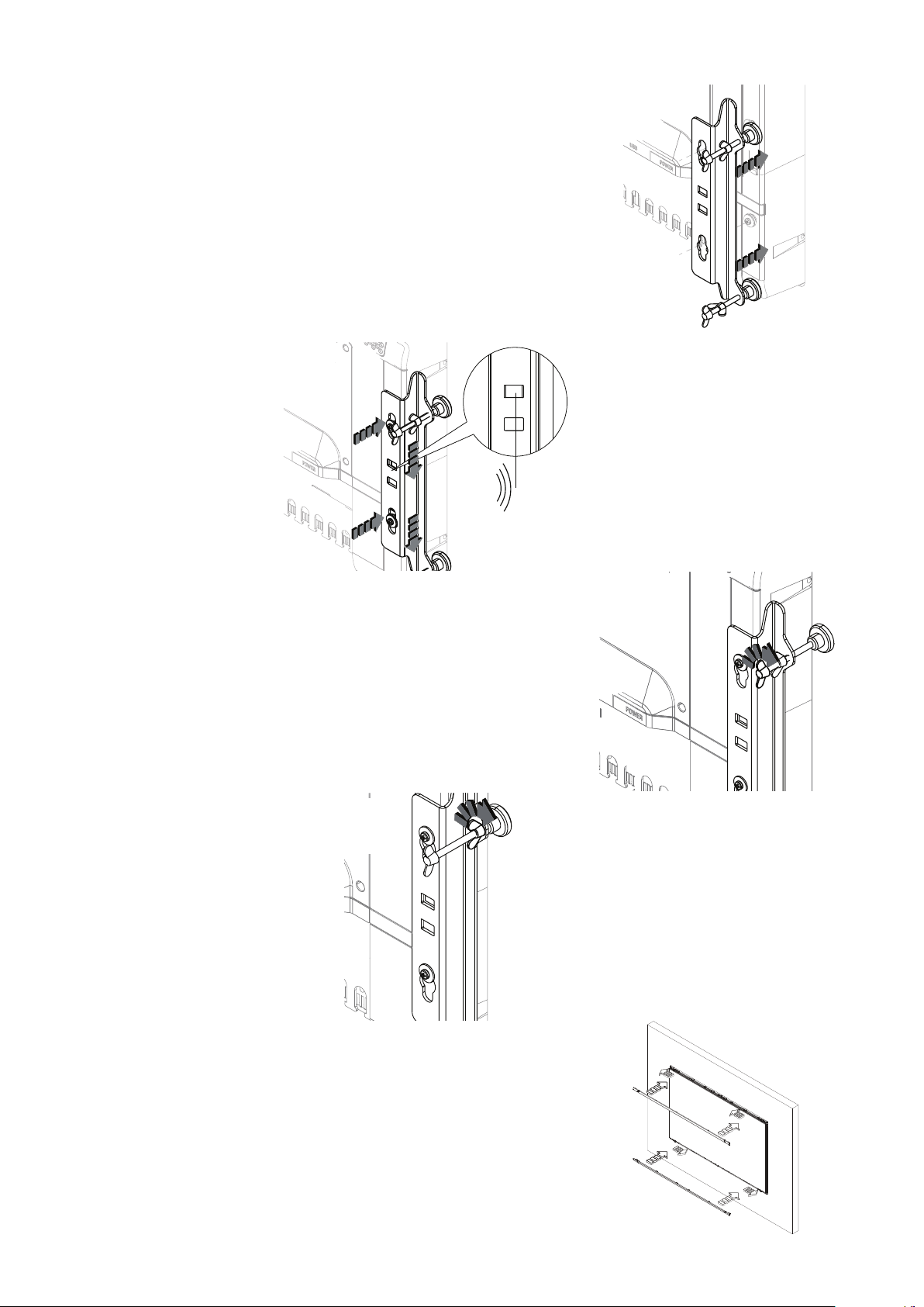
Fit brackets to rear of display, aligning ‘key
holes’ on bracket with screws on back of
display case.
CLICK
With bracket making contact with back of
monitor, slide bracket down till it engages
with a click and is held in place.
Wind in the wing screw, until stoppers make
rm contact with rear of dashboard material.
Check front of unit, ensuring that unit’s bezel is
making even contact with the dash surface.
When tting bezels, ensure hook tabs on back
of each bezel recess into opposing slots on
screen frame. Once ush with front surface of
screen, slide top bezel to the left, and bottom
bezel to the right to lock in to place.
Hand tighten wing nuts against the back of
the mounting brackets to lock the wing screw
in place. Hold wing screw stationary if it turns
while adjusting the wingnut.
Display installation | ZM Series User Manual
|
5
 Loading...