

B&G ZEUS2 9, ZEUS2 7 Installation Manual
ENGLISH
Zeus series
Installation Manual
bandg.com


Preface
As Navico is continuously improving this product, we retain the right to make changes to the
product at any time which may not be re ected in this version of the manual. Please contact
your nearest distributor if you require any further assistance.
It is the owner’s sole responsibility to install and use the instrument and transducers in a
manner that will not cause accidents, personal injury or property damage. The user of this
product is solely responsible for observing safe boating practices.
NAVICO HOLDING AS AND ITS SUBSIDIARIES, BRANCHES AND AFFILIATES DISCLAIM ALL
LIABILITY FOR ANY USE OF THIS PRODUCT IN A WAY THAT MAY CAUSE ACCIDENTS, DAMAGE
OR THAT MAY VIOLATE THE LAW.
Governing Language: This statement, any instruction manuals, user guides and other
information relating to the product (Documentation) may be translated to, or has been
translated from, another language (Translation). In the event of any con ict between any
Translation of the Documentation, the English language version of the Documentation will be
the o cial version of the Documentation.
This manual represents the product as at the time of printing. Navico Holding AS and its
subsidiaries, branches and a liates reserve the right to make changes to speci cations
without notice.
Copyright
Copyright © 2014 Navico Holding AS.
Warranty
The warranty card is supplied as a separate document.
In case of any queries, refer to the brand web site of your display or system:
www.bandg.com
Declarations and conformance
This equipment is intended for use in international waters as well as coastal sea areas
administered by countries of the E.U. and E.E.A.
Compliance Statements
The B&G Zeus series;
• complies with CE under R&TTE directive 1999/5/EC
• complies with the requirements of level 2 devices of the Radio-communications
(Electromagnetic Compatibility) standard 2008
The relevant Declaration of Conformity is available on the following website, under the model
documentation section:
www.bandg.com
Warning
The user is cautioned that any changes or modi cations not expressly approved by
the party responsible for compliance could void the user’s authority to operate the
equipment.
This equipment has been tested and found to comply with the limits for a Class B digital
device, pursuant to Part 15 of the FCC rules. These limits are designed to provide
reasonable protection against harmful interference in a residential installation. This
equipment generates, uses and can radiate radio frequency energy and, if not installed
and used in accordance with the instructions, may cause harmful interference to radio
communications. However, there is no guarantee that the interference will not occur in
a particular installation. If this equipment does cause harmful interference to radio or
television reception, which can be determined by turning the equipment o and on, the

user is encouraged to try to correct the interference by one or more of the following
measures:
Reorient or relocate the receiving antenna
• Increase the separation between the equipment and receiver
• Connect the equipment into an outlet on a circuit di erent from that of the receiver
• Consult the dealer or an experienced technician for help
Trademarks
• NMEA 2000 is a registered trademark of the National Marine Electronics Association
• Navionics is a registered trademark of Navionics SpA
• B&G, Lowrance, StructureScan, Navico, SonicHub, SimNet, Skimmer, InsightHD,
Broadband Radar, Broadband Sonar, and SonarHub are trademarks of Navico, registered
in the US and other countries
About this manual
This manual is a reference guide for installing the B&G Zeus series.
The manual does not cover basic background information about how equipment such as
radars, echosounders and AIS work.
Important text that requires special attention from the reader is emphasized as follows:
Note: Used to draw the reader’s attention to a comment or some important information.
!Warning: Used when it is necessary to warn personnel that they should proceed
carefully to prevent risk of injury and/or damage to equipment/personnel.

Contents
1 Zeus overview
2 Front - controls
3 Rear - connections
4 Hardware installation
4 Display mounting location
5 Display installation
7 Wiring
7 Guidelines
7 Power connection
8 Power Control connection
9 External alarm
10 Connect an external monitor
11 NMEA 2000 – connection to backbone
12 NMEA 0183 device connection
13 Ethernet device connection
13 Video in
14 Software setup
14 First time startup
15 Time and Date
15 Power Control setup
15 Sourc e s e l e c tio n
16 Device list
16 Network Groups
17 Diagnostics
17 External Alarm Setup
17 Radar setup
19 Video In con guration
20 Autopilot setup
26 Fuel setup
28 CZone setup
29 Software updates and data backup
30 NMEA 0183 setup
31 Ether net setup
32 Wi setup
34 Accessories
35 Supported data
35 NMEA 2000 compliant PGN List
38 NMEA 0183 supported sentences
39 Speci cations
40 Dimensioned drawings

| 1
Zeus2 overview | Zeus Installation Manual
Zeus overview
The Zeus range of multifunction displays consist of rugged marine displays with built in
powerful marine processors. Display size choices are 7”, 9”, and 12” . All models come with a
built in 10 Hz high gain GPS antenna.
The ability to network over NMEA 2000 and ethernet allows access to data as well as control
of numerous optional devices that can provide radar, audio entertainment, weather and even
digital switching.
All displays can operate on 12 V or 24 V systems.
Each size display may be ush or bracket mounted.
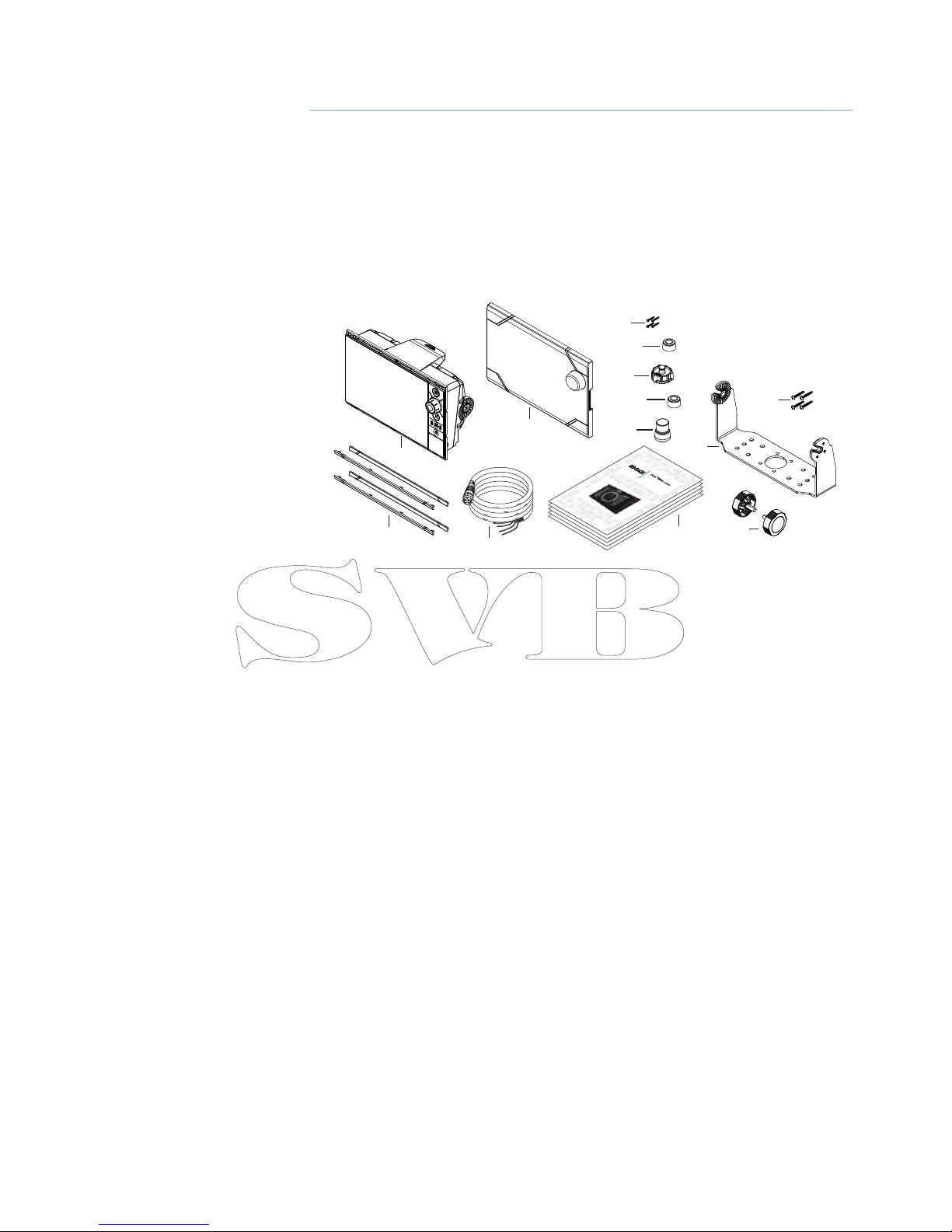
Included Items
1
3
2
11
4
12
13
5
7
8
9
10
6
E
NGLI
S
H
I
n
stall
a
t
i
on
Manual
band
g
.
c
om
E
NGLI
S
H
I
n
stall
ation
Manual
band
g
.
c
om
E
NGLI
S
H
In
stall
ati
on
M
anua
l
band
g
.
c
om
E
NGLI
S
H
I
n
stall
ati
on
Manual
band
g
.
c
om
E
NGLI
SH
I
n
stall
ation
Manual
band
g
.
c
om
1 Zeus display
2 Sun cover
3 Bezels trim (black and silver)
4 Power cable
5 Self tapping pozi screws, 4Gx1/2” (x4 for 7/9, x8 for 12)
6 Ethernet dust cap (x2 for Zeus 12)
7 HDMI dust cap (only for Zeus 12)
8 NMEA 2000 dust cap
9 Video/NMEA 0183 dust cap
10 Document pack (includes: installation manual, user manual, quick start guide,
templates, and warranty card)
11 Bracket
12 Bracket knobs
13 Self tapping pozi screws for bracket
2 |
Zeus2 overview | Zeus Installation Manual
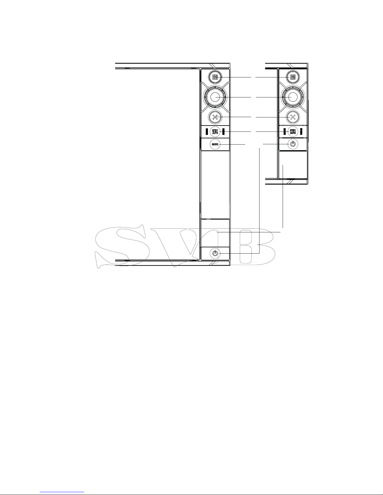
Front - controls
8
7
5
3
2
1
4
6
ZEUS 9/12 ZEUS 7
1 Touch screen - cursor control, chart panning and zoom, context related menus
2 Home key - opens home page for page selection and setup options
3 Rotary knob - zooming and menu scrolling / selection by press
4 Exit - exits menu dialogue, clears cursor from screen
5 STBY/AUTO - autopilot control
6 Mark - places waypoint at vessel location
7 Power - turns on unit, opens System Controls dialogue, long press turns o
8 Card reader door - access to dual card reader slot
| 3
Zeus2 overview | Zeus Installation Manual
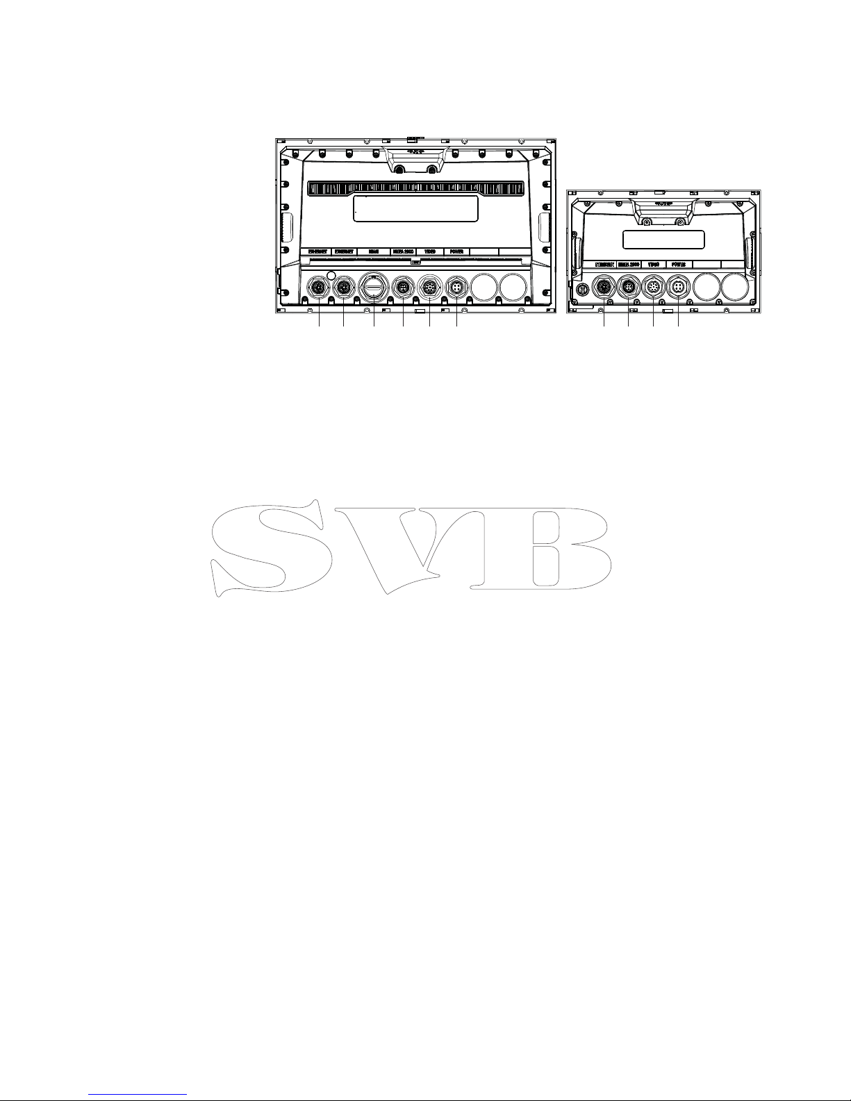
Rear - connections
5
31
4
54
21
3
1
ZEUS 9/12 ZEUS 7
1 Ethernet - connection to high bandwidth network modules
2 HDMI - video output for external monitor
3 NMEA 2000 - dynamic data and user database sharing
4 Video - input for video sources such as cameras
5 Power - 12 V or 24 V supply input
4 |
Hardware installation | Zeus Installation Manual
Hardware installation
Display mounting location
Choose the mounting locations carefully before you drill or cut; The display should be
mounted so that the operator can easily use the controls and clearly see the display screen.
B&G displays are high-contrast and anti-re ective, and are viewable in direct sunlight, but for
best results install the display out of direct sunlight. The chosen location should have minimal
glare from windows or bright objects.
If bracket mounting the display, choose an area where the display will not be subjected to
excessive vibration.
The mounting location will a ect the internal GPS receiver. Test the unit in it’s intended
location to ensure satisfactory reception. An external GPS source may be added to overcome
poor reception areas.
Leave su cient clearance to connect all relevant cables.
Check that it is possible to route cables to intented mounting location
Ensure that any holes cut are in a safe position and will not weaken the boat’s structure. If in
doubt, consult a quali ed boat builder.
Before cutting a hole in a panel, make sure that there are no hidden electrical wires or other
parts behind the panel.
Do not mount any part where it can be used as a hand hold, where it might be submerged, or
where it will interfere with the operation, launching or retrieving of the boat.
Choose an area where the unit will not be subjected to excessive vibration, or heat.
Choose a location that will not expose the unit to conditions that exceed the IP rating - refer
to “Speci cations” on page 39.
Note: Where ush mounted, the enclosure should be dry and well ventilated. The ventilation
of the space behind the unit should be enough to prevent excessive heat build up as a combined result of radiated heat o the heat sink, and sunlight heating of the enclosure. In very
small enclosures, it may be required to t forced cooling.
!
Warning: Inadequate ventilation and subsequent overheating of display may
cause unreliable operation and reduced service life. Ensure enclosure does not consistently exceed +55° C (+131° F) during normal daytime operation (in direct sunlight,
and at full screen brightness).
!
Warning: When installing, ensure appropriate safety equipment is used, e.g. ear
mu s, protective glasses, gloves and a dust mask. Power tools may exceed safe noise
levels, and can cast o dangerous protectiles. The dust from many materials commonly used in boat construction may cause irritation or damage to eyes, skin, and
lungs.
| 5
Hardware installation | Zeus Installation Manual
Display installation
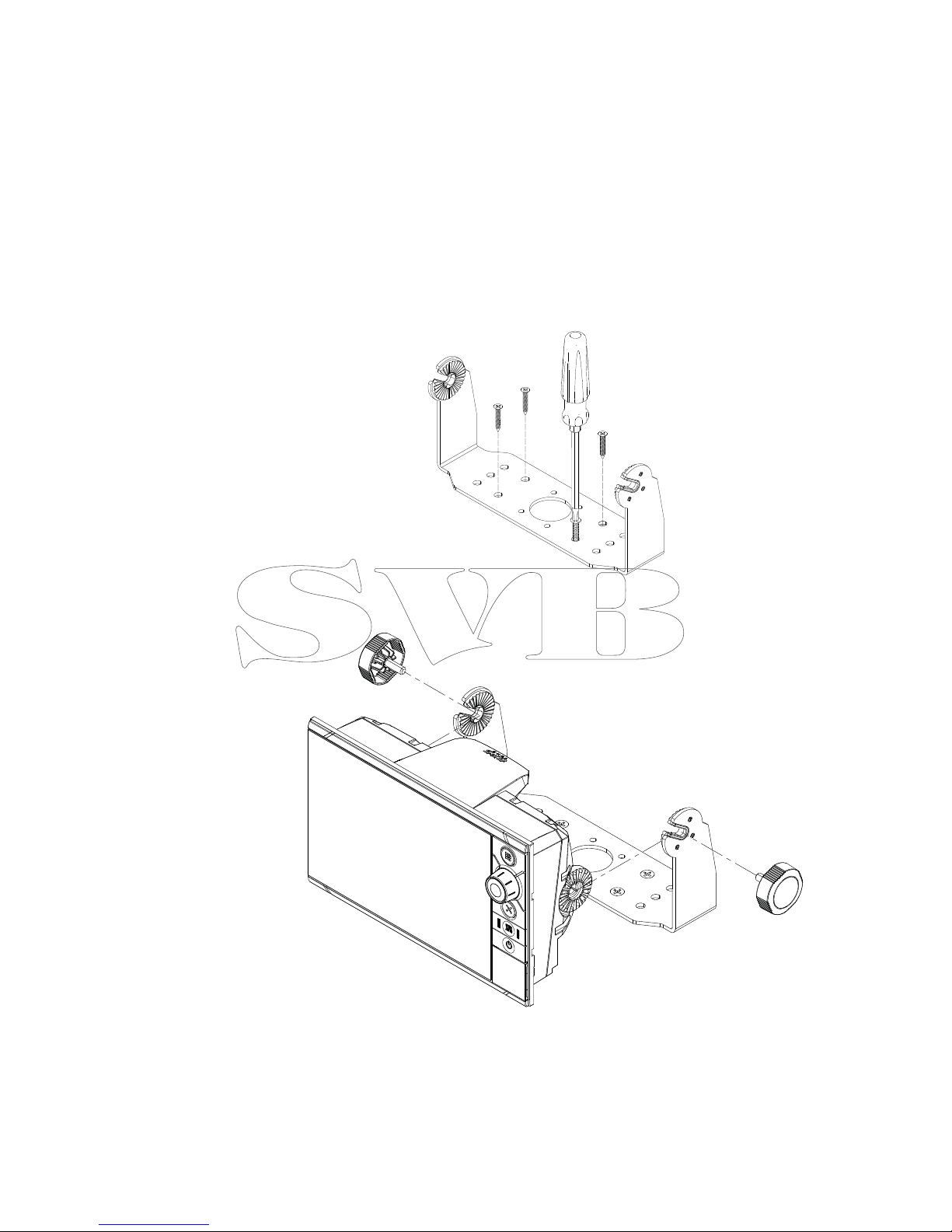
Bracket mounting
Place the bracket in the desired mounting location, and use a pencil or permanent marker to
mark drilling locations.
Note: ensure that the chosen location has enough height to accomodate the display tted in
the bracket, and allows tilting of the display. Also adequate space is required on both sides to
allow tightening and loosening of the knobs.
Use fasteners suited to the mounting surface material. If the material is too thin for self
tappers, reinforce it, or mount bracket with machine screws and large washers. Use only 304
or 316 stainless steel fasteners. Mark the screw locations using bracket as template, and drill
pilot holes.
Screw down the bracket.
Mount the display to the bracket using the knobs. Hand tighten only. The ratchet teeth in
the bracket and display case ensure a positive grip and prevent the unit changing from the
desired angle.
6 |
Hardware installation | Zeus Installation Manual
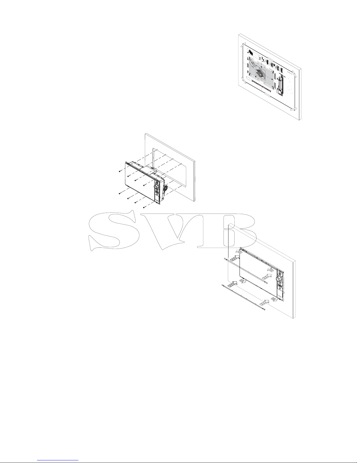
Flush mounting
Check the template for scaling accuracy, using a tape
measure or ruler against the ruler printed on the
template.
Cut away excess paper if required, and tape template
to mounting surface. Check it is correctly aligned to a
vertical or horizontal reference. Do not use a bubble
level as vessel may be listing! Adjust where required.
Drill all marked pilot holes, then using an appropriate
saw, cut through the template and mounting surface,
along the dotted line bordering the shaded area of the
template.
Check the t of the display, and le away
remaining obstructions. Secure the display
with the supplied screws. Once screws are fully
tightened, ensure there is complete contact
with the mounting surface.
Bezel Fitment and Removal
When tting bezels, ensure hook tabs on
back of each bezel recess in to opposing
slots on screen frame. Once ush with front
surface of screen, slide top bezel to the left,
and bottom bezel to the right to lock in to
place. The bezel trim have been designed
to be very low pro le, and therefore fully
conceal the locking tabs that keep them
from being accidentally disengaged from
the mounting ange. To release the locking
tab, it is necessary to gently lever the centre
of the bezel trim away from the mounting
ange. To remove the cover, simultaneously
slide it sideways; to the right for the top
bezel, and to the left for the bottom bezel.
REMOVE SH
A
DED AREA
*98
8
-10455
-
001*
NO
TE:
DO
NO
T SCALE
PRI
N
T
1
:
1
IMPO
R
T
AN
T
.
Do
no
t u
se t
his
t
emp
l
a
t
e if
i
t
has
b
e
e
n
r
es
c
al
ed
by
c
opy
i
ng
o
r prin
n
g
.
If t
his
i
s
no
t
t
he
o
rig
i
nal, o
r
is
a
pr
i
n
t
f
r
o
m a
le, please check
t
he di
m
en
si
on li
n
es below ar
e
t
o
s
c
ale b
e
fo
r
e
us
e.
I
M
P
O
R
T
AN
T
.
N
e
pas u
l
i
s
er ce
g
abar
it
s
’
il
a
é
t
é p
hot
o
c
opié ou
imprimé en
f
orm
a
t
r
éduit ou ag
r
a
ndi. Si ce
g
aba
r
it n
’
e
s
t ni un
original ni un
e
v
e
r
s
ion i
m
pr
i
mé
e
d
’
un
ch
i
er PD
F
, v
euill
e
z
v
éri
er qu’i
l
e
s
t à l
’
é
c
h
e
l
le
a
v
a
nt de
l
’
u
lise
r
.
I
MPO
R
T
ANTE
.
no usar la plan
lla
si h
a
y peligr
o que la es
c
ala
o
r
igina
l
e
x
a
c
t
a se ha al
t
e
r
ado por
c
opias o pr
o
c
esos de
imp
r
esi
ón
im
p
r
e
ciso
s
.
S
i
es
t
o no es el original,
o un PD
F
,
v
eri
c
a
r
q
u
e
l
as
lí
neas a
ba
j
o
e
s
tán
a la
es
c
ala a
n
t
es
de
u
sa
r
.
WICHTIG. Diese
n
Vo
r
dr
u
ck nic
h
t
v
e
r
w
e
n
den,
w
enn er du
r
ch
K
op
i
e
r
en
oder Dr
u
c
k
en im Maß
s
t
ab
v
e
r
ä
n
dert wu
r
de. So
ll
t
e
es nic
h
t das
O
r
ig
i
n
a
l
o
d
er
e
in
P
D
FAu
sdr
u
ck
se
i
n
,
m
üs
s
e
n
u
n
ten
s
t
eh
e
nde
Z
eile
n
vo
r
e
r
w
endung
an
den rich
g
en
M
aß
s
t
ab an
g
epa
s
s
t
we
r
den.
B
EL
A
N
GRIJK.
G
e
bru
i
k d
e
z
e
m
a
l
n
i
e
t
i
n
d
ie
n
d
e
sch
a
a
l is
v
e
r
an-
de
r
d
d
o
or
d
a
t h
e
t
i
s
g
e
c
opiee
r
d o
f
g
ed
ru
k
t
.
I
n
dien d
e
z
e
ma
l
n
i
e
t
h
e
t ori
g
i
n
e
el
o
f
ee
n
pr
i
n
t
v
a
n
P
D
F
is
,
c
o
n
t
r
o
l
e
er
da
n
o
f
d
e
on
d
e
r
s
t
aan
d
e
li
j
nen de
ju
i
s
t
e
s
chaal z
i
j
n
v
o
o
r
d
a
t
u
z
e
g
e
b
r
u
i
-
kt
.
IMP
O
R
T
ANTE.
Nã
o
u
l
i
z
e
e
s
t
e
g
ab
a
r
i
t
o
se
a es
c
ala do mesm
o
v
e
r
sido
al
t
e
r
a
da
po
r
c
ó
p
i
a ou imp
r
ess
ão
. S
e
n
ão
f
o
r
o
o
ri
g
i
na
l
o
u
uma
c
ó
pia i
m
p
r
es
s
a
d
e
u
m
a
r
q
ui
v
o
P
D
F
,
v
eri
q
u
e
as
l
i
nh
a
s
abai
x
o
,
pa
r
a a
c
er
t
a
r
a
e
s
c
ala
a
n
tes
da
u
li
z
a
ç
ã
o
.
VI
K
T
IGT
.
A
n
v
ä
n
d
i
n
t
e
d
en
n
a
mall
om
d
en
s
k
a
l
a
ts
o
m
g
eno
m
u
t
skri
e
l
l
e
r
k
op
ier
i
n
g. Om
d
e
a
i
n
t
e är or
i
g
i
n
al
e
t
eller
en
utskri
f
r
å
n en PD
F
,
k
o
n
t
r
o
ll
e
r
a
a
lin
j
erna
n
ed
a
n
s
t
äm
m
e
r
m
e
d
s
k
al
an
i
nna
n
d
e
t
a
n
v
ä
n
ds
.
IMP
O
R
T
A
NT
E
. Non
u
lizz
a
r
e que
s
t
o
m
o
d
ello
se
è
s
t
at
o
ridi
m
e
nsio
n
a
t
o
c
opia
n
d
o
l
o
o
st
ampa
n
dol
o
.
S
e
qu
e
s
t
o
no
n
è
l’
o
ri
g
in
al
e
o l
a
s
t
a
mpa d
i
u
n
le
PD
F
,
v
e
ri
c
a
r
e se le linee che
seguo
n
o
d
e
v
o
n
o esse
r
e
d
im
e
nsi
on
a
t
e prima di
e
ss
e
r
e
u
l
iz
z
a-
t
e
.
T
ÄR
K
E
Ä
Ä
.
Älä
k
ä
y
t
ä
t
ä
t
ä
k
a
a
v
i
o
t
a,
jos
sen
mi
a
k
a
a
v
a on
m
u
u
u
n
u
t
k
opio-i
de
ss
a
t
ai tulo
s
t
a
e
s
s
a.
J
os
t
äm
ä ei o
l
e
al
k
u-
pe
r
äi
n
en
t
ai
P
DF tu
l
o
s
t
e
t
arki
s
t
a
r
aj
a
t
m
i
a
k
a
a
v
a
s
t
a
a
l
la
en
n
en
k
ä
y
ö
ä.
⊼
ᛣ
˖
䇋
ሑ
䞣
ϡ㽕
Փ
⫼ᴀᅝ㺙ᣪ
ᄨ
ሎᇌ
⠜
ⱘ
ӊ
DŽ
བ
ᵰ
Փ
⫼
ӊˈ
߭
Փ
⫼
Пࠡ
䇋⹂
䅸݊
↨
՟ϔ
ᅮ
㽕
Ϣ
ӊ
ᇣ
ᖙ乏ϔ
㟈
DŽ
㩅
㟈
aG⸩㇠
⇌
G
㻐
⥙
㡰
⦐
G
䆠
ὤᴴ
G㦤
㥉G
═
G
㟤
G
㢨
G䊐䙀⫳㡸
G
㇠㟝
䚌㫴
G⫼㐡
㐐㝘
UG
㠄⸬
㢨G
㙸
⏼
ᶤ
⇌
G㢬㋸Ɒ㢨⮨SG
㇠㟝
䚌ὤ
G㤸G㙸⣌G㾌㍌㉔㢌G⌼
Ἴ
㡸G
䞉㢬
G
䚨
G㨰㐡㐐㝘
U
謗
ஔ
အြ႒
ႿႣ
Ⴘ
ー
႔
ွ襙
蕧ၒ
ၿႠ
ー
္ၖေ
ဴ
貽谞
ယ
変
ၝ
ေ
ဴ
ဒ
ၙ
အ
ံ
ယတၘ
၌
ဧ
ြဵ萦
蠯
ဥးဒ
ဵ
踆
ဣ
ဒ
ଟ
႒
ႿႣႸ
ー
႔
ယ
ၶ
Ⴖ
ႄ
႖
Ⴗြၐြ
ဵ
းဒ见踵္ွଞ踆
ြ
貎
茽
蓧
ၠ萦ေဴ貽谞ၠ輑襨ဥဴဝီ
ဣဒ
ଟ
ɩɴ
ɯɳɧ
ɴ
ɯɬaGɴʌG
ʏ
ʘʖʕʒʣʎʚʐ
ʙ
ʌG
ʤ
ʙʚGʏʔʘʙʗʚʑʝʏʥS
G
ʌʘ
ʒʏGʕʔʇ
G
ʈʢ
ʒʇ
Gʏʎʓ
ʌʔʌ
ʔ
ʇ
Gʉ
G
ʗ
ʇʎ
ʓ
ʌ
ʗʇʜG
ʖ
ʗ
ʏGʑʕʖʏʗʕʉʇ
ʔʏ
ʏGʏʒ
ʏG
ʗ
ʇ
ʘ
ʖʌ
ʞʇʙ
ʑʌ
U
G
ɬʘ
ʒʏ
G
ʉ
ʢ
Gʏ
ʘ
ʖ
ʕ
ʒʣ
ʎʚʌʙʌ
Gʔ
ʌ
Gʕʗ
ʏʊʏ
ʔ
ʇ
ʒ
S
Gʇ
Gʗ
ʇ
ʘ
ʖ
ʌʞ
ʇ
ʙ
ʑʚG
ʏ
ʎG
ʛʇ
ʐʒʇS
G
ʚʈʌʋʏ
ʙ
ʌ
ʘʣG
ʉ
G
ʘʕʕ
ʙʉʌʙ
ʘʙ
ʉ
ʏ
ʏGʗʇ
ʎ
ʓʌʗʕ
ʉ
G
ʒʏʔ
ʌʐʑ
ʏ
G
ʉ
G
ʔ
ʏʍ
ʔ
ʌʐG
ʞ
ʇ
ʘ
ʙʏGʏ
ʔʘʙʗʚʑʝʏ
ʏ
GʘG
ʋʌ
ʐʘʙʉʏʙʌʒ
ʣ
ʔʢʓʏGʗ
ʇ
ʎ
ʓʌ
ʗʇ
ʓʏU
Check dimensions before cutting
1
2"
3
0
0
m
m
L
C
L
C
192.5 mm (7.58")
186.0 mm (7.32
"
)
192
.5
m
m
(7.
5
8")
1
86.0 mm
(7.
32
")
20
0
.0
m
m
(7.
87
")
117.5 mm (4.63")
111.0 mm (4.37")
130.0 mm (5.12")130.0 mm (5.12")
117.5 mm (4.63")
111.0 mm (4.37")
2
0
0.0
mm
(7.8
7")
385
.0
mm (15
.
16")
3
72
.0
mm
(
14
.
65
"
)
4
00
.0
mm
(
15
.
75
"
)
235.0 mm (9.25")
222.0 mm (8.74")
260.0 mm (10.24")
MO16
Marine Monitor
X4
1
3
x4
x2
4
C
L
I
CK
5
6
7
2
| 7
Wiring | Zeus Installation Manual
Wiring
Guidelines
Care must be taken when running cables in a boat, to ensure that the cables are protected
from damage and do not interfer with mechanical systems such as throttle cables and hatch
covers.
At each end of a cable, it is advisable to leave a short loop hanging lower than the termination
point. This prevents any water that may get in contact with the cable from running down it to
termination points vulnerable to corrosion.
Extending cables should be done with suitable crimp connectors or solder and heat shrink.
Keeps joins as high as possible to minimize possibility of water immersion.
Routing cables adjacent to high current or high frequency signal cables could cause noise to
be induced from one device to another. Allow spacing between cables where possible.
Secure all cables at regular intervals, to prevent movement during boat operation. Cable
movement may cause fatigue at termination points or cause the cable to interfere with other
boat systems.
Allows enough cable slack for easy access to connectors when removing the device from a
bracket or ush mount installation.
!
Warning: Before starting the installation, be sure to turn electrical power o . If
power is left on or turned on during the installation, re, electrical shock, or other
serious injury may occur. Be sure that the voltage of the power supply is compatible
with the Zeus2 display
!
Warning: The positive supply wire (red) should always be connected to (+) DC with
the supplied fuse or a circuit breaker (closest available to fuse rating).
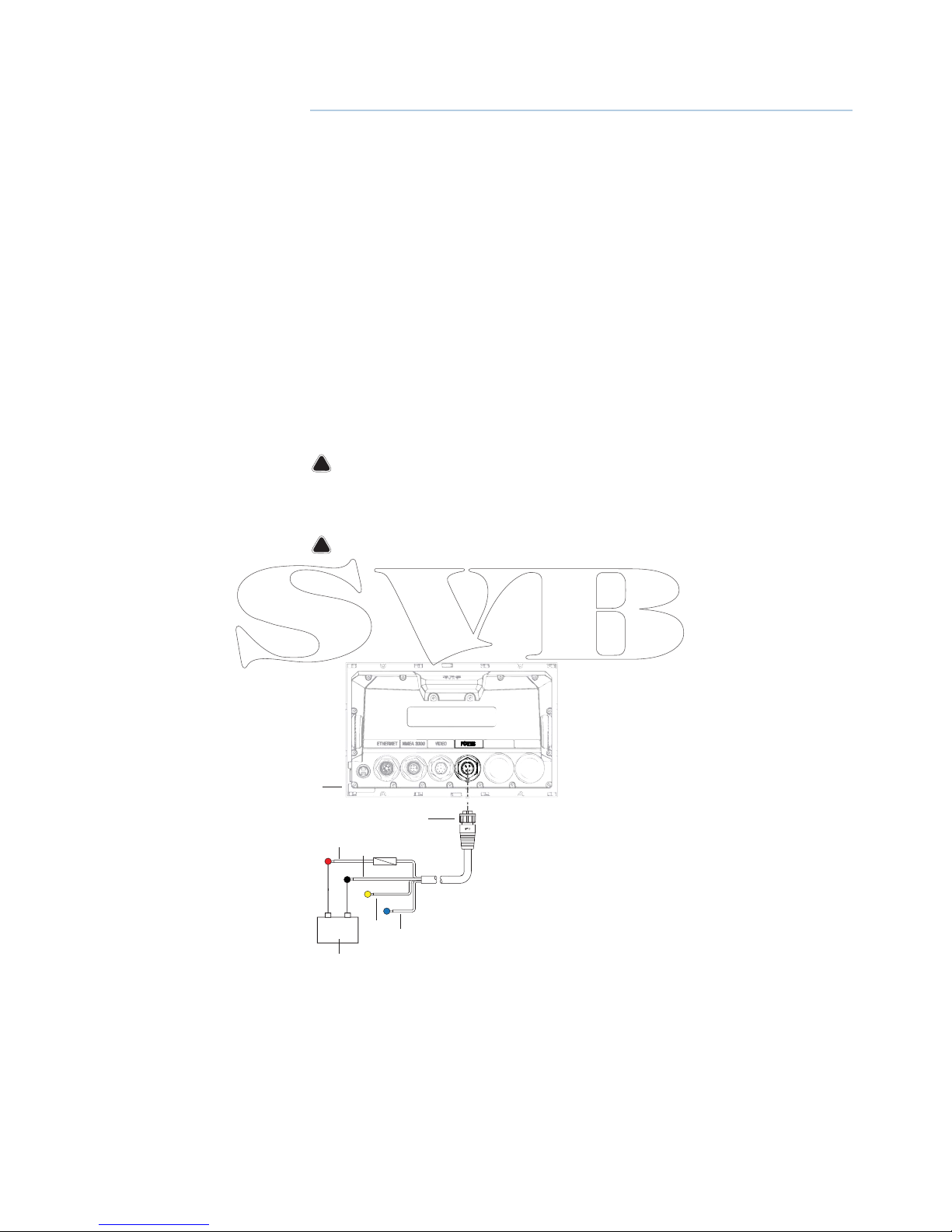
Power connection
Zeus displays are designed to be powered by a 12 or 24 V DC system. They are protected
against reverse polarity, under voltage and over voltage.
+
_
2
3
4
6
7
5
1
1 Zeus display
2 Four pin power cable
3 Positive supply, 12/24V (red wire)
4 Negative (black wire)
5 Power control (yellow wire)
6 Alarm output (blue wire)
8 |
Wiring | Zeus Installation Manual
Power Control connection
The yellow Power Control wire on the Zeus power cable can either be an input that will turn
on the processor when power is applied, or an output that turns on other devices when the
processor is powered on. It can be con gured at the installation stage to control the power
state of displays and compatible devices. When commissioning the system, the Zeus can be
set to be a Power Control Slave or Power Control Master.
Power Control con guration options of the Zeus are:-
• Zeus to turn on when power key pressed: Yellow wire not connected
• Zeus to turn on when power source is turned on: Common red and yellow wires
• Zeus to turn on with power key, as well as other compatible devices such as Broadband
Radar: Yellow wire connected to a Power Control Bus. (Set one or more displays to be a Power
Control Master)
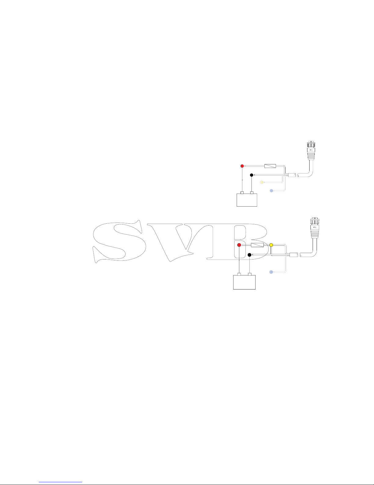
Power Control unconnected
Device will turn on and o when the power
button on the front of the unit is pressed.
Leave yellow Power Control wire disconnected.
Tape or heat-shrink end to prevent shorting.
Power Control to supply positive (auto on)
Device will turn on immediately when power is
applied. Common the yellow wire with the red
wire after the fuse.
Note: The unit can not be powered down by
power button, but can be put in to standby
mode. (screen backlight also turns o ).
+
_
+
_
| 9
Wiring | Zeus Installation Manual
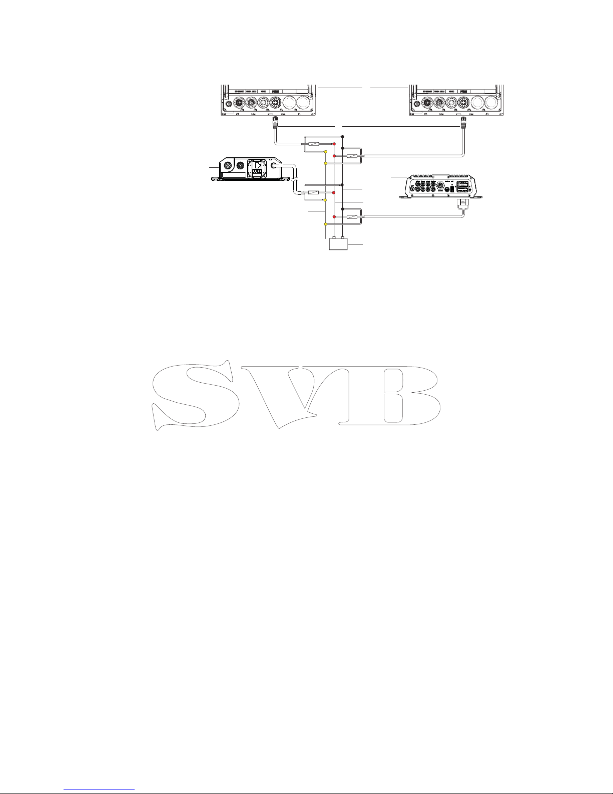
Power Control master/slave bus
Turning on the ‘master’ device turns on connected ‘slave’ devices.
1 Zeus displays
2 Power cable
3 Radar Interface box
4 Sonic Hub
5 Ground wire
6 Positive wire
7 Power control wire
If the left Zeus turns on using the power button and is set as the Power Control Master, it will
output voltage on the Power Control bus to power on the other Zeus, the Radar Interface,
and the SonicHub.
If the right Zeus is set to Power Control Slave, it cannot be powered down using its own
power button, but can be set to standby.
If the left Zeus (Power Control Master) is o , the right Zeus can be turned on using its own
power button, but won’t turn on any other devices.
To turn on all network devices from either Zeus, both devices can be con gured as Power
Control Masters.
Note: If an Zeus has its power state controlled by another device (or ignition switch), it can’t
be totally powered down. It can however enter a standby state to save power. If the power
button is pressed and Power O selected, a message will appear “Preparing to standby…”
External alarm
Blue wire on power cable:
An external alarm can be connected to one or more Zeus displays on the network. The
external alarm can be a small peizo buzzer connected directly, or a horn siren connected via a
relay.
Alarms are con gured globally in the system i.e they can be con gured on any one
networked multifunction device or Triton instrument, and be seen, heard, and acknowledged
from all devices. Individual devices can also be con gured to not to sound their internal
buzzer, but still display the alarm information. For information on con guring alarms, refer to
the Alarms section in the Operator manual.
+
_
6
3
2
7
8
5
4
1
 Loading...