

Page 1
Zeus Multi-function Display
Installer Manual
English
Page 2

Preface 1.
Disclaimer
As Navico is continuously improving this product, we retain the right to make changes to
the product at any time which may not be reflected in this version of the manual. Please
contact your nearest distributor if you require any further assistance.
It is the owner’s sole responsibility to install and use the instrument and transducers in
a manner that will not cause accidents, personal injury or property damage. The user of
this product is solely responsible for observing safe boating practices.
NAVICO HOLDING AS, AND ITS SUBSIDIARIES, BRANCHES AND AFFILIATES DISCLAIM
ALL LIABILITY FOR ANY USE OF THIS PRODUCT IN A WAY THAT MAY CAUSE ACCIDENTS,
DAMAGE OR THAT MAY VIOLATE THE LAW.
Governing Language: This statement, any instruction manuals, user guides and other
information relating to the product (Documentation) may be translated to, or has been
translated from, another language (Translation). In the event of any conflict between any
Translation of the Documentation, the English language version of the Documentation
will be the official version of the Documentation.
This manual represents the product as at the time of printing. Navico Holding AS and its
subsidiaries, branches and affiliates reserve the right to make changes to specifications
without notice.
Copyright
Copyright © 2010 Navico Holding AS.
Feedback from you
Your feedback is important and helps Navico ensure that this manual is a valuable
resource for all marine technicians. E-mail your comments or suggestions about this
manual to the following address: tech.writing@navico.com
Warranty
The warranty card is supplied as a separate document.
It is shipped with the product registration card.
In case of any queries, refer to the brand web site of your display or system.
www.bandg.com
Preface | 1
Page 3

Declaration of Conformity
Hereby, Navico Holding AS declares that this Z8, Z12 is in
GB
FI
NL
FR
SE
DK
compliance with the essential requirements and other relevant
provisions of Directive 1999/5/EC.
Navico Holding AS vakuuttaa täten että Z8, Z12 tyyppinen laite
on direktiivin 1999/5/EY oleellisten vaatimusten ja sitä koskevien
direktiivin muiden ehtojen mukainen.
Hierbij verklaart Navico Holding AS dat het toestel Z8, Z12 in
overeenstemming is met de essentiële eisen en de andere relevante
bepalingen van richtlijn 1999/5/EG.
Par la présente, Navico Holding AS déclare que ce Z8, Z12 est
conforme aux exigences essentielles et aux autres dispositions de la
directive 1999/5/CE qui lui sont applicables.
Härmed intygar Navico Holding AS att denna Z8, Z12 står i
överensstämmelse med de väsentliga egenskapskrav och övriga
relevanta bestämmelser som framgår av direktiv 1999/5/EG.
Undertegnede Navico Holding AS erklærer herved, at følgende
udstyr Z8, Z12 overholder de væsentlige krav og øvrige relevante
krav i direktiv 1999/5/ EF.
Hiermit erklärt Navico Holding AS, dass sich dieses Z8, Z12 in
DE
GR
IT
ES
PT
The equipment named in this declaration, is intended for use in international waters
as well as coastal sea areas administered by countries of the E.U. and E.E.A. A full
Declaration can be obtained from www.bandg.com
Übereinstimmung mit den grundlegenden Anforderungen und den
anderen relevanten Vorschriften der Richtlinie 1999/5/EG befi ndet.
(BMWi)
Με την παρουσα Navico Holding AS δηλωνει οτι Z8, Z12
συμμορφωνεται προς τις ουσιωδεις απαιτησεις και τις λοιπες σχετικες
διαταξεις της οδηγιας 1999/5/ΕΚ.
Con la presente Navico Holding AS dichiara che questo Z8, Z12 è
conforme ai requisiti essenziali ed alle altre disposizioni pertinenti
stabilite dalla direttiva 1999/5/CE.
Por medio de la presente Navico Holding AS declara que el Z8,
Z12cumple con los requisitos esenciales y cualesquiera otras
disposiciones aplicables o exigibles de la Directiva 1999/5/CE.
Navico Holding AS declara que este Z8, Z12está conforme com os
requisitos essenciais e outras provisões da Directiva 1999/5/CE.
2 | Preface
Disposal
Waste Electrical and Electronic Equipment (WEEE)
The use of the WEEE Symbol indicates that this product may not be treated as household
waste. By ensuring this product is disposed of correctly, you will help protect the
environment.
For more detailed information about the recycling of this product, please contact your
local authority, your household waste disposal service provider or the shop where you
purchased the product.
Page 4

Contents 2.
Preface ............................................................................................... 1
Introduction ....................................................................................... 6
About this Manual ............................................................................6
Conventions ................................................................................... 6
Important Safety and Warning Information ......................................... 6
Check the Parts .............................................................................. 7
Overview ............................................................................................ 8
Installing the Display .......................................................................... 10
Mounting location .......................................................................... 10
Panel Mount ................................................................................. 11
Bracket Mount .............................................................................. 12
System Architecture ........................................................................... 14
Networking, Data Interfacing .......................................................... 14
SimNet / NMEA 2000 14
Ethernet: (NETWORK ports) 14
NMEA0183 14
B&G H-Link 14
Data Bridging ............................................................................... 15
Wiring Information ............................................................................. 16
Typical System .............................................................................. 16
Standard Connections .................................................................... 17
NMEA0183 Devices 17
H3000 17
Deckman Navigation Software 17
WTP3 18
Wiring the Zeus Display ...................................................................... 19
Power .......................................................................................... 20
Connecting Power 20
Power Control 20
External Alarm .............................................................................. 23
H-Link ......................................................................................... 24
B&G H-Link LT 24
B&G H-Link Pro 24
SimNet ........................................................................................ 25
Planning and Installing a SimNet Backbone 26
Power the SimNet Network 26
Preface | 3
Page 5

Ethernet ...................................................................................... 28
Dual and Multi Station 29
NMEA0183 Wiring .......................................................................... 30
Video In ....................................................................................... 31
Video Out ..................................................................................... 32
Connecting BroadBand™ Radar ....................................................... 33
Connecting HD Radar ..................................................................... 34
Connecting BSM1 Broadband Echosounder ....................................... 35
Commission the System...................................................................... 36
Turning on the system for the fi rst time ........................................... 36
Operating the Menu System ............................................................ 36
Commissioning Checklist ................................................................ 37
System settings menu 38
Language 38
Time: Local Time, Time format, Date Format 38
Power Control 38
Echosounder Setup ........................................................................ 39
Radar setup .................................................................................. 40
Data Setup ................................................................................... 42
SimNet / NMEA2000 setup 42
Source Selection (Auto select) 42
Source Selection (Manual) 42
Damping 45
Device List 45
Serial Port Setup ........................................................................... 46
NMEA 0183 Output 46
Fuel ............................................................................................. 47
Vessel Setup 47
AIS Own Vessel ............................................................................. 47
Diagnostics ................................................................................... 48
NMEA2000 Diagnostics 48
User Database UDB 48
Check GPS Signal .......................................................................... 49
4 | Preface
System Backup ............................................................................. 49
Creating a System Backup File 49
Restore a System Backup File 50
Software Upgrades ........................................................................ 50
Displaying current software version 50
Screen Capture ............................................................................. 52
File Transfer ................................................................................. 52
Page 6

Drawings ............................................................................................ 53
Z8 Dimensions .............................................................................. 53
Z12 Dimensions ............................................................................ 54
Spare Parts ......................................................................................... 55
Zeus Spare Parts ........................................................................... 55
Zeus Optional Accessories .............................................................. 55
Compatible BSM-1 Transducers 56
SimNet Accessories ....................................................................... 56
Ethernet Cables (yellow) 57
Ethernet Cables (RJ45) 57
Repeat Screens 57
Video Cables for Repeat Screens 57
Specifi cation s ..................................................................................... 58
Supported NMEA0183 Sentences ..................................................... 59
NMEA 2000 PGN List ...................................................................... 60
NMEA 2000 PGN Receive 60
NMEA2000 PGN Transmit 61
Preface | 5
Page 7

Introduction 3.
About this Manual
This manual is a reference guide for installing the B&G Z8 and Z12 Multi Function
Display.
The information in this manual at the time of printing is correct to the best of our
knowledge. Navico can not be liable for any inaccuracies or missing information.
Due to the constant improvement of Navico’s products. Navico cannot be liable for
changes between the product and the manual. Refer to www.bandg.com for the latest
manuals, addendum’s and software updates.
Conventions
Used when it is necessary to warn personnel that a risk of damage to the
equipment or injury/death exists if care is not exercised.
Used to draw the reader’s attention to a comment or some important information.
Important Safety and Warning Information
Please read carefully before use.
When navigating the vessel, use the B&G Zeus system only as a navigational
aid. Proper navigation of the vessel is the sole responsibility of the vessel
operator.
The electronic chart used by the Zeus System is an aid to navigation only
and is designed to supplement, not replace, offi cial government charts. Only
offi cial government charts supplemented by notices to mariners contain the
information required for safe and prudent navigation. Always supplement the
electronic information provided by the B&G Zeus with other plotting sources
such as observations, depth soundings, radar and hand compass bearings.
Should the information not agree, the discrepancy must be resolved before
proceeding any further.
Never operate the Zeus in Simulate Mode while you are underway. It is
the user’s responsibility to ensure that Simulate Mode is used only in safe
situations such as when you are moored in a marina.
The Global Positioning System (GPS) is operated by the US Government which is
solely responsible for its operation, accuracy and maintenance. The GPS system
is subject to changes which could affect the accuracy and performance of all
GPS equipment anywhere in the world.
6 | Introduction
The accuracy of the Echosounder depth display can be limited by many
factors, including the type of transducer, the location of the transducer, and
water conditions. Ensure that the transducer is installed correctly and the
Echosounder is used correctly.
Page 8
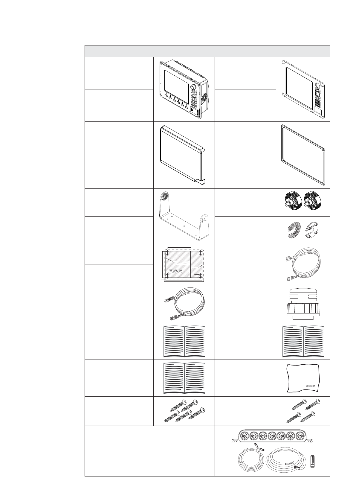
Check the Parts
Packaged Parts List
8“ Display unit
PN location specifi c
12 “ Display unit
PN location specifi c
Z8 Sun cover
000-10408-001
Z12 Sun cover
000-10407-001
Z8 Mounting bracket
000-00136-001
Z12 Mounting bracket
000-00137-001
Z8 Bezel
000-10406-001
Z12 Bezel
000-10405-001
Z8 Gasket
Z12 Gasket
Bracket knobs
000-00138-001
2 x Ratchet washers
Z8 Mounting Template
988-0186-03
Z12 Mounting Template
988-0186-04
Video-In / Comms
Cable
000-00129-001
Z8, Z12
Installation Manual
988-0186-01
Z8, Z12
Quick start guide
988-0186-02
5 x SCREW,14G x
1,PAN POZI,S/T,SS
316,BLACK
212 mm (8.34”)
192 mm (7.55)
5 mm (0.20”)
CLEARANCE HOLE TO SUIT M4 MACHINE SCREW
OR DRILL PILOT HOLE TO SUIT SELF TAPPING SCREW
CUTOUT
Check dimensions before cutting
265 mm (10.40”)
285 mm (11.20)
265 mm (10.40”)
PRODUCT OUTLINE
192 mm (7.55”)
25 mm (1.00”)
Power cable
000-00128-001
Connector Caps
000-00130-001
Operation manual
988-0186-00
Cleaning cloth
4 x SCREW,
8Gx1, PAN POZI,
S/T,16,LO-HEAD
SimNet Starter Kit: Includes
• 24005845 SimNet 5 m (16.5 ft) cable
• 24006298 SimNet 7-Prong Multi-Joiner
• 24005894 SimNet Termination Plug
• 24005902 SimNet 2 m (6 ft) power cable
w/terminator
Introduction | 7
Page 9
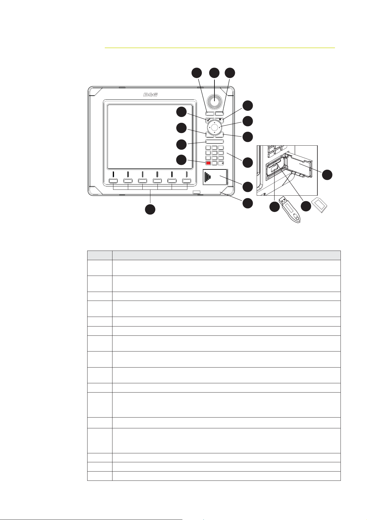
Overview 4.
2 4
3
PLOT
5
GO TO
MARK
VESSEL
7
8
6
MENU
10
12
ECHORADARCHART NAV INFO PAGES
WIN
IN
OUT
MOB
ABC DEF
123
JKLGHI MNO
456
TUV
PQRS
WXYZ
7
809
STBY
PWR
AUTO
9
11
13
16
1
15
Key Description
Direct Access Keys (DAK). Provide direct access to a page. Repeated presses
1
of each DAK cycles through several different pages that relate to the DAK
PLOT/MARK key. A short press activates the Plot menu, a long press positions
2
a waypoint at the vessel position
3 Rotary knob. The function of the knob is depending on active context
GOTO/VESSEL key. A short press activates the Goto menu, a long press
4
centers the chart to vessel position
5
3 key — Activates/confi rms current selection
6 X key cancels changes and returns to previous menu level
Cursor keypad used to move the cursor on the display, and to maneuver in the
7
menu system
MENU key. Used to display the context menu for the active panel/overlay, and
8
for selecting options in edit mode. . 2 x MENU for system settings menu
WIN key, used on multiple panels pages. A short press toggles between the
9
panels, a long press expands active panel to a full page panel and back again
10 Zoom buttons for radar, echosounder and chart pages
Alpha numeric keypad used for entering numbers and text in dialog boxes.
11
A long press on the “1” key will position a Man Over Board (MOB) waypoint at
the vessel’s current position
12 STBY AUTO - Future use
Media port door. Press and slide to the right to open.
13
Media can be used for optional Navionics chart data, software updates,
transfer of user data and system backup
14 SD /MMC media card slot.
15 USB por t
16 Removable bezel
13
14
8 | Overview
Page 10
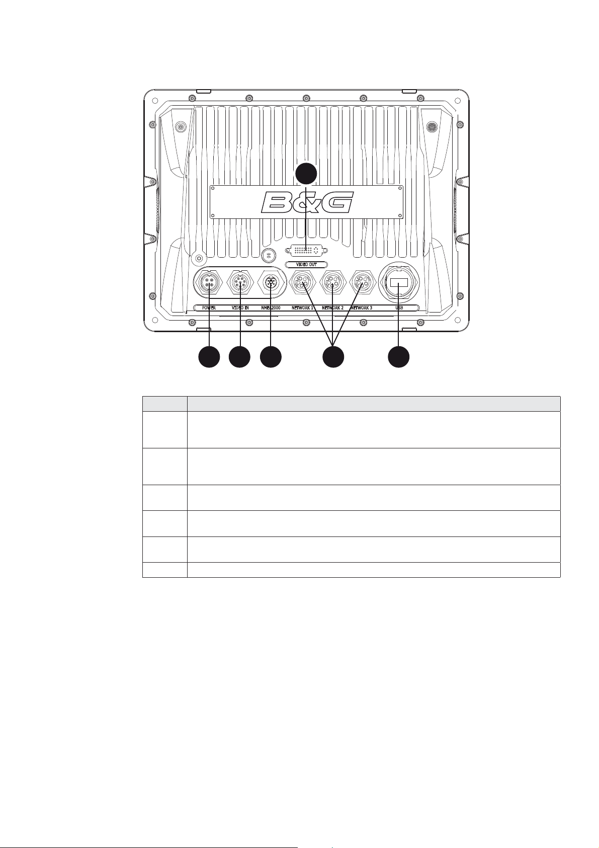
4
1 2 5 63
Key Description
Power. For power input 12 or 24 V DC input (see power section), Power
1
control (see Power Control section) and external alarm (see External
Alarm section.
Video In. Supplied cable provides two composite video inputs (see Video In
2
section) and one RS422 port (NMEA0183 TX, RX) see NMEA0183 Wiring
section.
SimNet. Connects Zeus display to a SimNet or NMEA2000 network (see
3
SimNet section).
Video Out. Connect to an external monitor via optional DVI cable (see Video
4
Out section).
Network 1, 2 and 3. Three Ethernet network ports for connecting to other
5
Zeus displays and Network modules. (see Ethernet section)
6 USB. Used for H-Link Communications
Overview | 9
Page 11

Installing the Display 5.
Mounting location
Choose the mounting locations carefully before you drill or cut. The display should be
mounted so that the operator can easily use the controls and clearly see the display
screen. Be sure to leave a direct path for all of the cables. The display screen is highcontrast and anti-reflective, and is viewable in direct sunlight, but for best results install
the display out of direct sunlight. The chosen location should have minimal glare from
windows or bright objects.
Ensure that any holes cut are in a safe position and will not weaken the boat’s structure.
If in doubt, consult a qualified boat builder.
At least 100 mm (4”) away from the compass, at least 300 mm (12”) away from any
radio transmitter and at least 1.2 m (4 ft) away from any antenna.
Before cutting a hole in a panel, make sure that there are no hidden electrical wires or
other parts behind the panel.
Do not mount any part where it can be used as a hand hold, where it might be
submerged, or where it will interfere with the operation, launching or retrieving of the
boat.
If bracket mounting chose a flat area where the display will not be subjected to excessive
vibration.
Leave sufficient clearance space behind the display to connect all relevant cables.
Good ventilation is required behind the mounting panel. Poor ventilation may cause the
display to overheat. The display is designed to operate in temperatures from -15° C to
+55° C (+5° F to +131° F).
For overall width and height requirements, please see the drawings at the back of this
manual.
10 | Installing the Display
Page 12
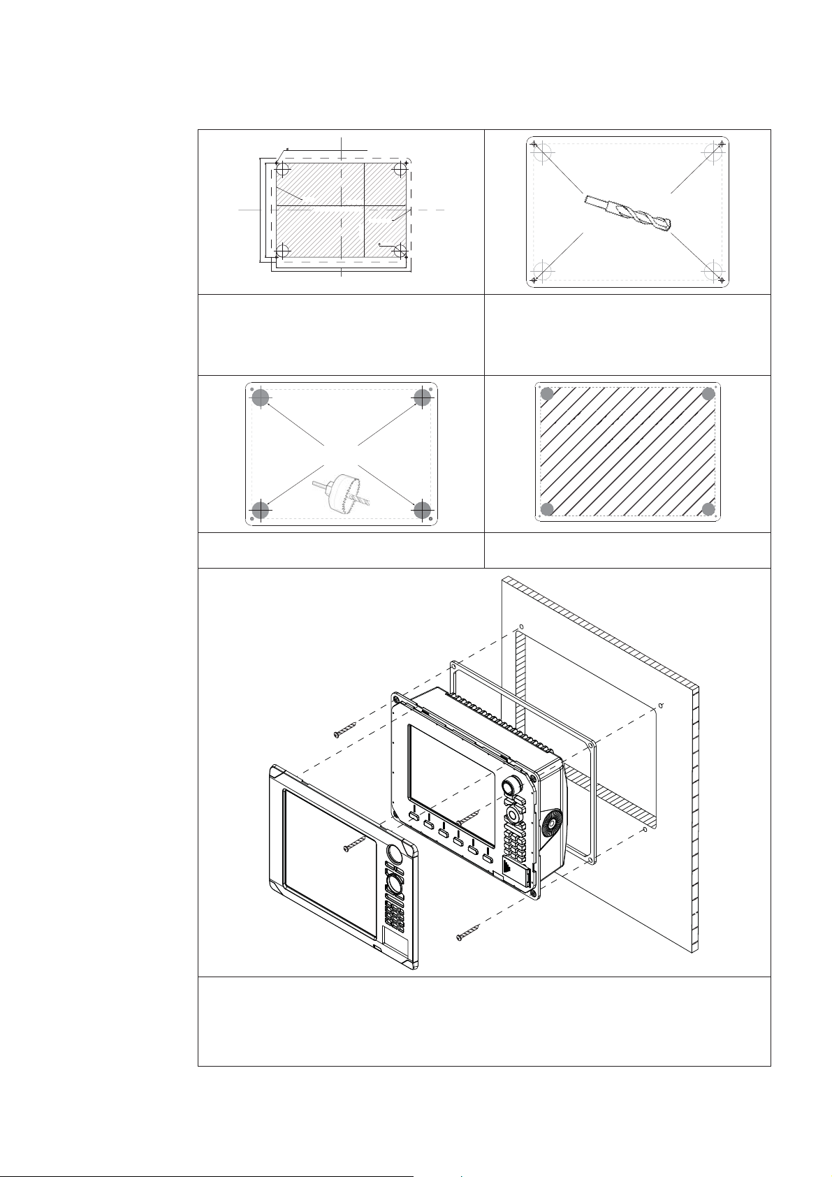
Panel Mount
s
5 mm (0.20”)
CLEARANCE HOLE TO SUIT M4 MACHINE SCREW
OR DRILL PILOT HOLE TO SUIT SELF TAPPING SCREW
212 mm (8.34”)
192 mm (7.55)
CUTOUT
265 mm (10.40”)
Check dimensions before cutting
265 mm (10.40”)
285 mm (11.20)
192 mm (7.55”)
PRODUCT OUTLINE
25 mm (1.00”)
Attach the fl ush mounting template 1
to the selected mounting position
using adhesive tape.
A
Use a 25mm (1 “) hole saw to cut 3
the four corner radius
Drill pilot holes for the four hole saw 2
cuts and four self tapping screws
used to secure the display. If using
M4 machine screws use a 5 mm
(0.20 ”) drill bit.
Cut out shaded
area
Cut along the dotted line and 4
remove the shaded area.
Peel backing off the gasket and apply to the surface. 5
Connect all cables to the rear of the unit before placing the unit into the console. 6
Secure the display to the surface7
To fi nish off the installation fi rmly clip the front bezel in place8
Installing the Display | 11
Page 13
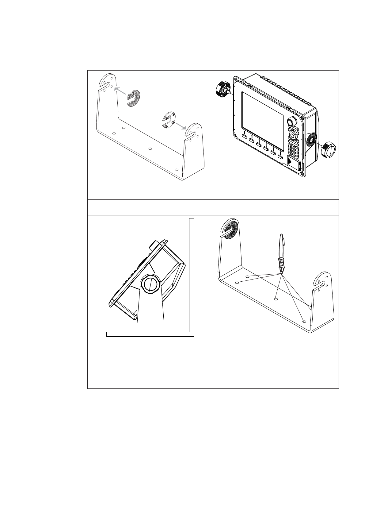
Bracket Mount
An alternative to flush mounting the Z8 or Z12 is to bracket mount the unit. This method
has the advantage that the display can easily be removed when not in use. The display
may be tilted for best possible viewing angle when bracket mounted.
Press the ratchet washers into the 1
bracket.
Temporarily mount the display 3
unit in the bracket and make sure
the display can be adjusted to the
correct angle without interfering
with the surrounding. Allow space
for cables attached to the rear of
the unit.
Loosely screw securing knobs to the 2
Display unit.
Remove the display unit and use the 4
mounting bracket as a template to
mark the fi ve positions of the screw
holes.
12 | Installing the Display
Page 14
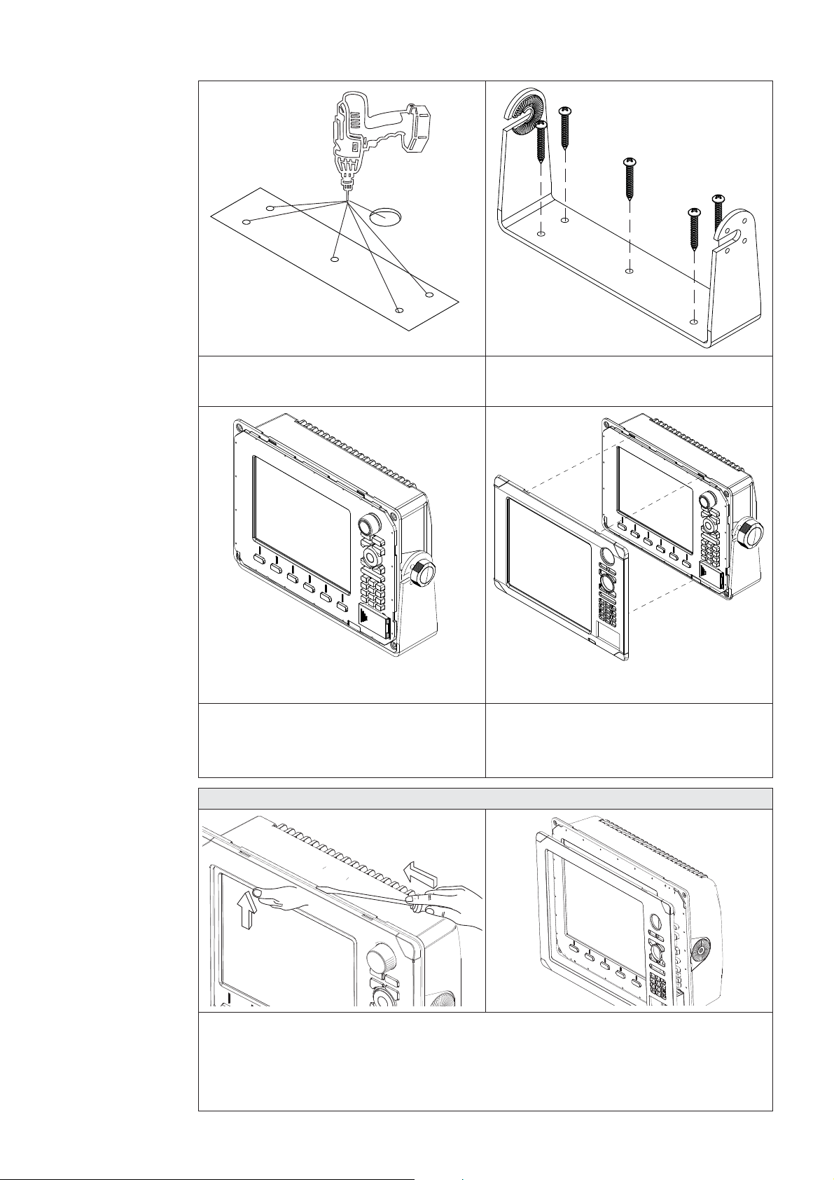
Drill a pilot hole for the fi ve screws 5
and an optional hole large enough
for the cables to emerge from.
Secure 5 the bracket to the surface6
Connect the cables.7
Slide the display into the mounting 8
bracket and secure in place with the
bracket knobs.
Zeus Bezel Removal
Attach the bezel. Firmly clip the 9
front bezel in place.
C
B
A
Protect the dash area adjacent to the top edge (or bottom edge) of the display.
Apply upwards pressure on the bezel (A), this will create an opening between the
bezel and the case. Insert a medium size fl at blade screw driver into the gap (B) Slide
the screw driver along the gap to release the clips along the top. Continue down the
side until the bezel releases. The same routine can be applied to the bottom edge if
accessible.
Installing the Display | 13
Page 15

System Architecture 6.
This section explains how the Zeus connects to other devices as part of a system. The
Zeus has a highly scalable system architecture. A system can consist of a basic stand
alone chart plotter, or expand to a networked, multi-display system connected to a wide
range of accessories.
The system architecture is modular with a wide range of peripherals and accessories
that can be connected to SimNet or NMEA2000 devices such as instrument systems,
AIS, GPS and heading sensor to Ethernet devices such as Radar and Echosounder. For
multi display installations the system can be set up to be truly masterless, i.e. have no
dependency on other displays being powered on.
A Zeus display can connect to other devices in the system by Ethernet, SimNet /
NMEA2000 or NMEA0183.
A system can have:
between one and six displays, the displays can be any mix of Z8 and Z12 •
one or two radars •
one echosounder •
one StructureScan •
Networking, Data Interfacing
The Zeus system can use four data protocols. SimNet (NMEA2000), Ethernet, NMEA0183.
and H-Link.
SimNet / NMEA 2000
SimNet is a proprietary CAN bus network for transfer of navigation data such as wind, •
Position, AIS, etc between all SimNet or NMEA2000 devices on a SimNet/NMEA2000
network.
SimNet is lower bandwidth than the Ethernet network, but is 50 times faster than •
NMEA0183
Ethernet: (NETWORK ports)
Zeus uses an Ethernet network for the transfer of high bandwidth data between other •
Zeus displays and from network modules such as Radar, Echosounder and Weather
module
Each Zeus display has three Ethernet network ports. An optional 5 port expansion •
port is available. (Recommended for multiple Zeus displays)
Ethernet does not transfer navigation data such as position, heading etc. This is •
handled either by SimNet and or NMEA 0183. However navigation and display settings
are synchronized over Ethernet
NMEA0183
NMEA0183 is a point to point connection. Each Zeus display has one NMEA0183 port •
using RS422 protocol. Each display can output to one NMEA0183 “Listener” and
receive from one NMEA0183 “Talker”.
14 | System Architecture
B&G H-Link
H-Link is B&G’s protocol for comprehensive and efficient interfacing of the B&G H3000 •
processor range with the Zeus chartplotters and external PC navigation programs.
H-Link Communications are available with Zeus via USB cable. •
Page 16
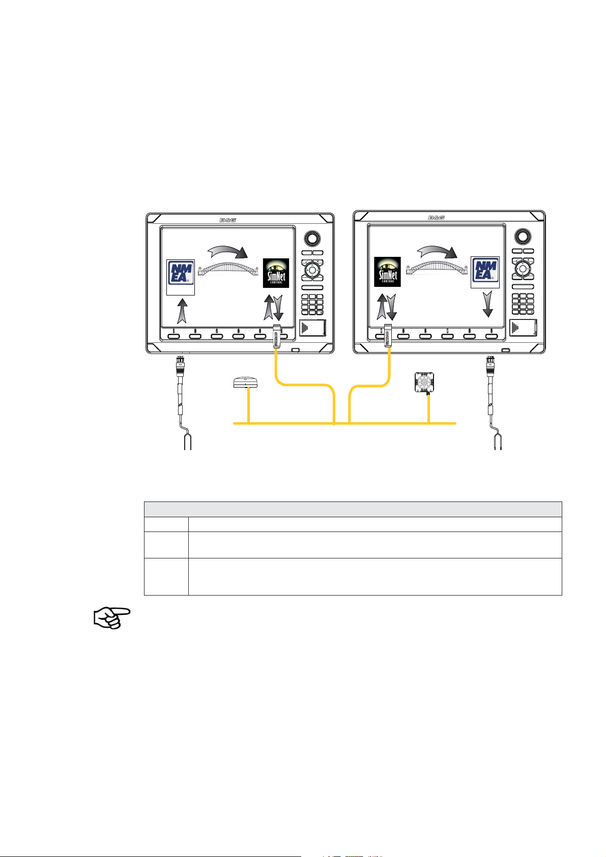
Data Bridging
Supported NMEA0183 sentences entering the system are bridged (converted) to •
SimNet/NMEA2000 and distributed on the SimNet backbone for all other displays to
use
Certain SimNet /NMEA2000 PGNs (messages/sentences) are bridged across to •
NMEA0183 to be available as an output from any Zeus display
Ethernet to SimNet. Limited data is bridged from the Ethernet echosounder. Speed, •
depth and temperature are bridged to SimNet and NMEA0183. Depth, speed and
temperature data from the echosounder is the only data bridged from Ethernet
DISPLAY 1
0183
RX -
NMEA0183 Talker
B
ECHORADARCHART NAV INFO PAGES
RX +
A
PLOT
MARK
MENU WIN
OUT
RANGE
MOB
123
GHI
4
PQRS
7
89
STBY
0
AUTO
GPS
SimNet Network
ABC DEF
JKL
TUV
DISPLAY 2
PLOT
GOTO
VESSEL
IN
MOB
MNO
65
WXYZ
PWR
ECHORADARCHART NAV INFO PAGES
NMEA0183
MARK
MENU WIN
OUT
RANGE
MOB
123
GHI
4
PQRS
7
89
STBY
0
AUTO
ABC DEF
JKL
TUV
GOTO
VESSEL
IN
MOB
MNO
65
WXYZ
PWR
Heading
SimNet Network
TX -
TX +
NMEA0183 Listener
C
Example of Data Bridging
A In this example a NMEA0183 (talker) is connected to DISPLAY 1
B The NMEA sentences are bridged across to SimNet and distributed on the
SimNet network
C The NMEA0183 listener connected to DISPLAY 2 can receive the NMEA0183
sentences from the device connected to DISPLAY 1 and also from other
devices that are on the SimNet network
An NMEA talker can be connected to each Zeus display and both set of data will be
converted to SimNet. Each display can be setup for outputting selected NMEA sentences.
Speed, temp and depth data from the echosounder transducer that is to be displayed
as an instrument has to bridged from ethernet to SimNet. A Zeus display has to be
nominated to bridge the data. If this nominated display is turned off, no data will be
displayed, until the display is turned on or another display is selected to bridge the data
(see Source Selection).
NMEA0183 to SimNet bridging only applies to the NMEA0183 sentences outlined in the
Supported NMEA0183 Sentences section of this manual.
System Architecture | 15
Page 17
Wiring Information 7.
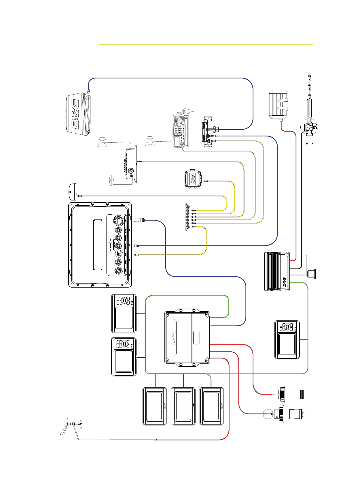
Typical System
Broadband Radar
Halcyon Gyro
Stabilised Compass
VHF Antenna
AIS
NAIS-300
Ant
GPS
ZG50
Zeus Z12
Radio
NMEA 2000
Compass
Gimballed Rate
7 way joiner
RI10
Hydraulic RAM
Sensor
Rudder
Unit
Masthead
Pilot Processor
CPU
GFD Displays
HV
Displays
20/20
H3000
H3000
GPD Display
Sensors
Speed & Depth
16 | Wiring Information
Page 18

Standard Connections
NMEA0183 Devices
Zeus Display
Video / Comms - NMEA0183
H3000
NMEA0183 Device
Zeus Display H3000
H-Link (USB)
Deckman Navigation Software
Zeus Display
H3000
Deckman
Navigation Software
Video / Comms - NMEA0183
Wiring Information | 17
H-Link (USB)
Page 19
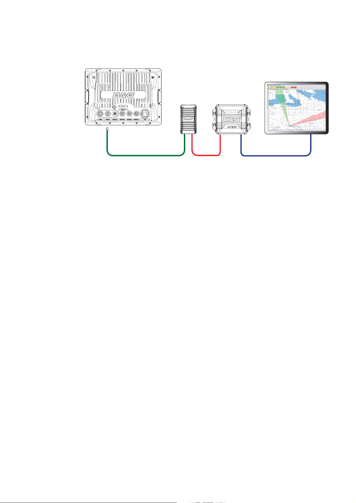
WTP3
Zeus Display
Video / Comms - NMEA0183
Serial
Interface
Can
Network
WTP3
Deckman
Navigation Software
Ethernet
18 | Wiring Information
Page 20

Wiring the Zeus Display 8.
Wiring guidelines
Most installation problems are caused by shortcuts taken with system cables. When
wiring the Zeus, follow the guidelines below.
Don’t Do This Do This
Don’t make sharp bends in the cables Do make drip and service loops
Don’t run cables in a way that allows water
to fl ow down into the connectors
Don’t route the data cables in areas
adjacent to radar, transmitter or large
current carrying cables
Before starting the installation, be sure to turn electrical power off. If power
is left on or turned on during the installation, fi re, electrical shock, or other
serious injury may occur. Be sure that the voltage of the power supply is
compatible with the Zeus display
The Zeus has a voltage rating of 12 V DC or 24 V DC. (9 V DC - 32 V DC max
range). NMEA2000 is 12 V DC only
Do tie-wrap all cables to keep them secure
If cables are shortened, lengthened, or
re-terminated, seal and protect all wiring
connections
Do leave room at the back to install and
remove cables
The red wire should always be connected to (+) DC V using a fuse or thermal
breaker (10 Amp)
Wiring the Zeus Display | 19
Page 21

Power
The Zeus displays can be powered by either 12 V or 24 V DC. Displays are protected
against reverse polarity, under voltage and over voltage.
The supplied power cable has a four core cable used for:-
power into the system (Red and Black wires) •
controling power state of the display or power state of other displays and devices •
(Yellow wire)
connecting to an external alarm (Blue wire) •
1
4
32
Power Cable (000-00129-001) Con. Pin Wire
color
2 m (6.5 ft)
1 Black Battery (-)
2 Blue External Alarm
3YellowPower control
4 Red Battery (+)
Function
12 - 24 V DC
Connecting Power
The red wire should always be connected to (+) DC V using a fuse or thermal
breaker (10 Amp)
Power Control
The yellow (Power Control) wire can either be an input that will turn on the display when
power is applied, or an output that turns on other devices when the display is powered
on. It can be configured at the installation stage to control the power state of displays
and compatible devices. Planning is required how you want to be able to turn on and off
compatible devices. When commissioning the system, displays can be set to be a Power
Control Slave or Power Control Master.
Power Control configuration options are:-
Use the Power button to turn on the display only: Yellow wire not connected •
Display to turn on when power is applied to the display: Common red and yellow wires •
Use the Power button to turn on the display and other displays and or compatible •
devices such as BroadBand™ Radar: Yellow wire connected to a Power Control Bus.
(Set one or more displays to be a Power Control Master)
20 | Wiring the Zeus Display
Page 22

Black
Red (FUSE)
Black
Red (FUSE)
Yellow
Blue
_
+
No Connect
No Power Control
Display will turn on and off when the
power button on the front of the unit
is pressed. Power Control wire is not
attached
12 - 24 V DC
Auto Power on
Display will turn on when power is applied
to the display. Common the yellow wire
with the red wire after the fuse.
Note: The unit can not be powered down
but can enter a standby mode.
Yellow
Blue
_
+
12 - 24 V DC
Power Control Master Power Control Slave
AB
Black
Red
Yellow
C
BR24 Radar
Power Control Master
Display (A) turns on using the power button. It is set as the Power Control Master and
will output voltage on the Power Control bus to turn on display (B) and BroadBand™
Radar (C). Display (B) is set to Power Control Slave and if turned on by display (A)
cannot be powered down using its power button, but can be set to standby. If display
(A) is off, display (B) can be turned on using its power button, but won’t turn on any
other devices. Display (B) could, however also be set to Power Control Master.
Black
Red
Yellow
Power Control Bus
+
Black
Red
Yellow
_
12 - 24 V DC
Wiring the Zeus Display | 21
Page 23

Power Control Table Slave Master
Can turn on by own PWR button YES * YES
Can turn off by own PWR button YES * YES
Can turn on other devices NO YES
Can be turned on or off by another device YES YES
Can turn off entire system if started by an
NO NO
ignition switch
Can have more than one on a system YES YES
* If Power control wire is not connected.
If a display has its power state controlled by another display or ignition switch, it can’t be
totally powered down. It can enter a standby state to save power. If the power button is
pressed and Power Off selected, a message will appear “Preparing to standby…”
To confi gure a display as a Power Control Slave or Master please refer to the Power
Control Setup.
22 | Wiring the Zeus Display
Page 24

External Alarm
An external alarm can be connected to one or more displays on the network. The
external alarm can be a small peizo buzzer connected directly or a horn siren connected
via a relay.
Alarms are configured globally in the system i.e they can be configured on one display
and seen, heard and acknowledged from all displays. How ever the external alarm siren
can be enabled or disabled on individual displays. For information on configuring alarms
refer to the Alarms section in the Operation manual
x2
MENU9WIN
Black
Red (FUSE)
Yellow
Blue
_
+
1 A max
35 V DC max
For sirens that draw more than 1 Amp use a relay
12 - 24 V DC
Black
Red (FUSE)
12 - 24 V DC
Yellow
Blue
_
+
Wiring the Zeus Display | 23
Page 25

H-Link
H-Link is B&G’s protocol for comprehensive and efficient interfacing of the B&G H3000
processor range used in conjunction with Zeus chartplotters and external PC navigation
programmes.
There are two versions of H-Link depending on the H3000 processor you are using.
B&G H-Link LT
H-Link LT is a version of the B&G data communication protocol providing an interface to
Zeus displays. This allows high speed two way data communications and access to True
Wind Calibration tables. H-Link LT is available on H3000 Hydra and Hercules CPUs.
Polar data is not available on H3000 Hydra and H3000 Hercules Processors.
B&G H-Link Pro
H-Link Pro is the full version of the B&G data communication protocol, it is available on
H3000 Hercules Performance and H3000 Hercules Motion CPUs.
H-Link Pro provides a full instrument interface with the Zeus Display. In addition to the
high speed two way data communications and access to the True Wind Correction Tables,
H-Link Pro will allow the full use of the Polar features in Zeus, and will allow you to
display Target speed and Target Angle information.
24 | Wiring the Zeus Display
Page 26

SimNet
SimNet is a data network based on NMEA2000 CAN bus technology that makes
interconnection and integration of B&G and NMEA2000 products simple. SimNet
permits the exchange of data between the interfaced products and enables the flow
of commands and instructions between the various SimNet and NMEA2000 compatible
products. The data transfer capability of SimNet is 50 times higher than the NMEA0183
standard at 4800 baud.
The advanced SimNet Plug & Play (P&P) function provides flexibility and automatic
interface setup to B&G products. Previous models of B&G products that are not SimNet
compatible and non-B&G products also benefit from this P&P setup function.
Certain NMEA0183 data can be converted to and from the SimNet network by;
connecting directly to the NMEA0183 port on an Zeus Display •
using and optional converter unit such as the AT10 •
connecting to a device that has the built-in capability to convert NMEA0183 to SimNet •
/ NME2000
Most NMEA2000 devices can be connected directly to a SimNet backbone and SimNet
devices can be connected to a NMEA2000 network by using adapter cables. (see SimNet
cables list)
SimNet Connector
1
5
2
3
4
Pin Function
1CAN_H
2 SimNet power (+) 12 V DC
3 SimNet power (-)
4Shield
5CAN_L
SimNet is a proprietary data network based on NMEA2000 CAN bus. •
SimNet is a powered network. It must have a separate 12-15 V DC power supply •
protected by a 5 Amp fuse. Do not connect the SimNet power cable to the same
terminals as the start batteries, Autopilot Computer, Radar, thruster or other high
current products.
A SimNet network consists of a linear “backbone” from which “drop cables” to SimNet •
devices connect. Devices that have more than one SimNet connector can be part of a
SimNet backbone (daisy chained) (But not as part of a NMEA2000 backbone).
A drop cable is a SimNet cable that connects a SimNet device to the backbone. A drop •
cable has a maximum length of 6 m (20 ft).
A SimNet Network • has a maximum cable length of 120 m (394 ft), which includes
drop cables + 30 m (98.5 ft) mast cable. Total 150 m (500 ft) max.
A SimNet network, needs to have a terminator at each end of the backbone. A •
terminator can be one of the following:
a power cable with built in terminator (red cap) a terminator plug (red cap) terminated in-line joiner (red locking collars) a wind transducer (terminator is in the mast head unit as opposed to mast cable). -
Wiring the Zeus Display | 25
Page 27

NMEA2000 devices can be connected to the SimNet Network providing they: •
are NMEA2000 certified meet the CE, FCC regulations with a SimNet adapter cable do not exceed the SimNet load specification (please refer to separate document -
B&G SimNet Installation Manual (20222006)
Planning and Installing a SimNet Backbone
Plan the SimNet backbone carefully
For part numbers refer to SimNet Accessories.
The SimNet backbone needs to run between the locations of all SimNet products you
want to install, and be less than a 5.5 m (18 ft) cable run from a SimNet device.
Choose from the following components to make up your SimNet backbone
SimNet cables: 0.3 m (1 ft), 2 m (6,6 ft), 5 m (16.6 ft), and 10 m (33 ft) cables •
SimNet power cables with or without termination •
SimNet in-line joiner with or without termination •
T-Joiner. Use at locations where you want to connect a single SimNet device or join •
lengths of SimNet cable
7 way joiner. Use to connect up to 5 devices at one location •
Wind transducer. If using a wind sensor, plan to connect this to one end of the •
backbone as this has a terminator built in
Power the SimNet Network
A SimNet network requires its own 12 V DC power supply protected by a 5 amp fuse or
breaker. For 24 V use a DC-DC converter
Connect power at one end of the backbone for smaller systems using a SimNet power
cable with termination (red cap).
For larger systems introduce power at central point in the backbone to “balance”
the voltage drop of the network. Use SimNet cable without termination (yellow cap)
(24005910) (See system drawings following)
If joining to an existing NMEA2000 network or similar CAN bus network that has it’s own
power supply, do not connect to another power supply.
Do not connect the SimNet power cable to the same terminals as the start batteries,
Autopilot Computer, Radar, thruster or other high current products
The following drawing shows a small SimNet network. Power is introduced at one
end using a SimNet power cable with termination ending with a second terminator.
26 | Wiring the Zeus Display
Page 28

F
T T
+
-
12 V DC
SimNet drop cable
ABC D E
A slightly larger system below. Power is connected at one end using terminated power
cable. A second terminator is required at the end of the backbone.
SimNet power
SimNet terminator
T
F
SimNet drop cable
SimNet backbone
SimNet power
SimNet terminator
T
G
T
_
+
12 V DC
C
B
A
Key Description
A SimNet power source. Stable 12 V DC only
B 5 Amp fuse or breaker
CSwitch
D SimNet power cable with termination (red disc) (24005902)
E SimNet 7 way joiner
F SimNet or NMEA 2000 GPS antenna
G SimNet backbone to RI10.
H SimNet backbone to Rudder Reference Unit
ED
H
T
Wiring the Zeus Display | 27
Page 29

Ethernet
The Zeus system uses an Ethernet network to interconnect high bandwidth devices such
as other Zeus displays, radar and echo sounder. Each Zeus display has three network
ports with 5 pin connectors. Ethernet network cables have orange connectors that are
retained by a bayonet type locking collar.
If more than three network devices need to be connected, use the optional network
expansion Port.
For multi-station systems it is recommended to use a network expansion port to join two
or more displays. Connecting this way removes the dependency of another display being
powered on that may have an Ethernet device connected, such as a radar
Ethernet connector
5
4
1
3
2
Pin Function
1 TX +
2 TX 3 RX +
4 RX 5GND
Single Station
28 | Wiring the Zeus Display
Broadband Sounder ™
Broadband Radar™
Page 30

Dual and Multi Station
If there is more than one display it is recommended to use a network expansion port
Network Expansion Port
NETWORK NETWORK NETWORK NETWORK
POWER
NETWORK
Broadband Radar™
Broadband Sounder™
Alternatively you can connect two or more Zeus displays without an network expansion
port. However, this will mean any display with a device connected by Ethernet will need
to be powered on for other Zeus displays to use the device.
DISPLAY A DISPLAY B
Broadband Sounder™
Broadband Radar™
Display (A) must always be on to enable radar and echo sounder data transfer to
DISPLAY (B)
Wiring the Zeus Display | 29
Page 31

Connecting to Navico HD Radar / Older Sirius Weather module
(RJ45 Ethernet connectors)
AB
Ethernet Adapter cable yellow 5 pin to
Navico RJ45 cable. refer Ethernet Cables
(yellow).
Navico RJ45 Ethernet cable.
Refer to Ethernet Cables (RJ45) for part
numbers.
NMEA0183 Wiring
To exchange NMEA0183 data, the Zeus display units have a NMEA0183 communication
port.
The port uses RS422 protocol and can be configured in the software for different baud
rates. NMEA sentences can be turned on or off. See Serial Port Setup.
Refer to Supported NMEA0183 sentences for a complete list of sentences
17
6
8
5
4
VIDEO IN
RS422
2
3
Pin Function
1 Video 1 Ground
2 Video 1 (+)
3 Video 2 Ground
4 Video 2 (+)
5 RS422 TX 6 RS422 TX +
+
+
A
-
B
-
7 RS422 RX +
8 Rs422 RX -
A Red Video in port 1
B Green Video in port 2
C
30 | Wiring the Zeus Display
RX RX +
TX TX +
Key Pin Color Cable color description Cable Connector
8 Orange RS422 RX 7 Green RS422 RX +
6 Yellow RS422 TX +
5 Blue RS422 TX -
TX TX +
RX RX +
NMEA0183 Talker
NMEA0183 Listner
C
Page 32

Video In
Connect up to two composite video cameras to each display unit using the supplied Video
/ Data cable. This connects to the VIDEO IN port on the rear of the display. Video inputs
are only displayed locally and are not distributed to other displays. Only one video input
can be viewed at a time. Video inputs can be cycled.
Video In Connector
17
VIDEO IN
Pin Function
1 Video 1 Ground
VIDEO 1
VIDEO 2
Video In / Data Cable (000-00129-001)
2 Video 1 (+)
3 Video 2 Ground
4 Video 2 (+)
5 RS422 TX 6 RS422 TX +
7 RS422 RX 8 Rs422 RX +
2
+
+
6
8
3
5
4
A
-
B
-
C
Key Color Description
A Red Video in port 1
B Green Video in port 2
Orange RS422 RX -
Green RS422 RX +
C
Wiring the Zeus Display | 31
Yellow RS422 TX +
Blue RS422 TX -
Page 33

Video Out
The Zeus display has a DVI-I Video connector. Connect a second display to replicate
what is on the screen of the Zeus display.
A DI10 display can only interface to Z8 and DI15 only to Z12 due to fixed resolutions.
The MO19 or other scalable monitor or TV can be connected to either Z8 or Z12
MO19
Or third party monitor
From Z8 or Z12
(scales to resoloution)
B
DI15
From Z12
only
(1024x768)
VIDEO OUT
DI10
From Z8
only
(800x600)
Video-Out cable part numbers (Optional)
Key Part Number Description
A AA010152 3 m (9.8 ft) Video cable DVI-HD26 for DI10/DI15
AA010154 10 m (33 ft) Video cable DVI-HD26 for DI10/DI15
AA010162 5 m (16.5 ft) HDMI small connector option for DI10 or
DI15 displays
AA010164 15 m (50 ft) HDMI small connector option for DI10 or
DI15 displays
B AA010157 5 m DVI -DVI video cable for MO19 monitor
A
32 | Wiring the Zeus Display
Page 34

Connecting BroadBand™ Radar
SimNet
Network
Scanner cable
A
B
Power
C
D
E
G
FF
G
HH
IJ
White RX+
Brown RX-
_
+
AT10HD
NMEA0183 to SimNet
Converter Heading Only
Cut off 12 Pin
plug to expose bare wires
Alternative: NMEA0183 heading
Key Description
AZeus Display.
B BroadBand™ Radar system for Zeus. Includes parts C,D and E.
C Scanner cable. 20 m (65 ft) : Optional 10 m (33 ft) and 30 m (98 ft).
D RI10 Radar interface box.
E Ethernet cable. BroadBand™ Radar comes with a 2 m (6.5 ft) 5 pin cable. The
RI10 can be connected directly to Zeus or via a Network Expansion Port. See
Ethernet cables yellow for more cable length options.
F SimNet Drop Cables: The BroadBand™ Radar and Zeus are connected to
the SimNet backbone BroadBand™ Radar uses heading at 10 hz to calculate
MARPA. (Not included)
G Power cable. (see Power section). Always use a fuse or breaker.
H SimNet backbone. Refer to SimNet section.
I Power control bus: In this case BroadBand™ Radar is connected to Power
Control Bus. BroadBand™ Radar is turned on when the Zeus is powered on.
J For MARPA and chart overlay use a heading sensor.
Either a SimNet / NMEA2000 heading sensor such as the GRC3. Or if a
NMEA0183 10 hz heading sensor is installed, convert to SimNet using a AT10HD
or connect to the NMEA in port on a Zeus. Refer NMEA0183 Wiring.
TX+
TX-
NMEA0183 10 Hz Heading
(e.g Gyro, Sat Compass)
Wiring the Zeus Display | 33
Page 35

Connecting HD Radar
2 kW 12 V DC ONLY
4 kW & 6 kW 12 or 24 V DC
10 kW & 25 kW 24 V DC ONLY
D
Ethernet
A
AT10HD
Scanner
B
C
D
F
I
E
HH
K
G
AA010070
K
J
TX+
_
+
NMEA0183 10 Hz Heading
(e.g Gyro, Sat Compass)
Key Description
AZeus Display.
B HD radar system for Zeus. Includes parts C,D and E. 2kw & 4 kW Radome.
6 kW, 10 kw and 25 kW open array options
C Scanner cable. 20 m (65 ft) .
E Ethernet cable RJ45 (male/male). Available in 2,5 and 10 m, (6.5, 16.5 & 33 ft)
For cable options see Ethernet Cables RJ45.
D HD Radar Processor
F Ethernet Adapter cable. Yellow 5 pin (Male) to RJ45 (female) 2 m (6 ft). The HD
radar can be connected directly to Zeus or via a Network Expansion Port. See
Ethernet cables (yellow) for more cable length options.
G AT10HD: SimNet to NMEA0183 converter (Heading only @ 10 Hz). Provides
heading to the radar processor for MARPA calculations
H SimNet backbone. For more information refer to the SimNet section.
I SimNet drop cable.
J SimNet heading sensor
K Power cable. Make sure a fuse is used. See Radar installation manual for fuse
size. Note voltage requirements are model dependant
TX-
Alternative: NMEA0183 heading
RX+ White
RX- Brown
AT10HD cable(cut off plug)
RX- White
RX+ Black/White
AA010070 Utility cable
34 | Wiring the Zeus Display
Page 36

Connecting BSM1 Broadband Echosounder
A
F
2
1
3
7
6
4
5
B
D
_
+
Key Description
A Zeus Display
B BSM-1 Broadband Echosounder module
Ethernet cable yellow 5 pin see Ethernet cables yellow for more cable
C
length options. Cable can be connected directly to Zeus or via a Network
Expansion Port see Ethernet.
D 12 or 24 V DC
E Transducer: See compatible transducer list.
F Transducer Connector
Pin 1
Pin 2 Speed
Pin 3 Speed power
Pin 4 Temp
Pin 5 Depth Pin 6 Shield
Pin 7 Temp / speed ground
Depth +
C
E
B
Wiring the Zeus Display | 35
Page 37

Commission the System 9.
Turning on the system for the fi rst time
Before starting the system for the first time, check the following;
Check radar is physically clear to rotate •
Leave a HD pulse radar in standby for 30 minutes before transmitting for the first •
time
Check all personnel are clear of radar beam (HD Radar) •
Check all wiring is correctly connected. Apply power to the breaker •
To turn ON the display, press and release the PWR key.
To place display in to Standby, press PWR key and select stand by.
To turn OFF the display, press and hold PWR key for three seconds.
If you turn the unit ON when no external equipment is connected you will be asked to
run in simulator mode.
Operating the Menu System
In this manual you will see few direct text references to keys, menus and menu entries,
and few step-by-step descriptions. By using graphics we will guide you to the key and
the required menu selections.
In the illustrations throughout the commissioning section the following symbols are used:
x2
MENU WIN
Press twice on
illustrated key
MENU WIN
3 s
Single short press
on illustrated key
Press and hold on
illustrated key with
time indication
MENU WIN
Single short
Rotate rotary knob
press on rotary
knob
PLOT
GO TO
MARK
VESSEL
PLOT
MARK
GO TO
VESSEL
References to keys on the operator panel are written in boldface, e.g. WIN key.
For further information on the operating the system refer to the Operation Manual
36 | Commission the System
Page 38

Commissioning Checklist
The Zeus has a number of advanced features which can be configured through the
settings menu.
It is recommend you become familiar with the operation of the unit using the default
settings before making any changes to these menus.
Settings menus will vary depending on the optional sensors and devices attached.
Before changing system settings make sure that all displays are powered on as a lot of
settings are global and are shared across the Ethernet network.
It is recommended to note the original settings before making adjustments or changes.
Zeus Related Check List Check
System
Set Language
Set Units
Set time
Set Time and Date format
Set power control option if used. Repeat on all relevant displays
Data sources
Perform auto source selection
Perform any manual source set up
Set NMEA0183 baud rate and output sentences. Settings relevant to displays
with NMEA0183 devices attached.
Set up of SimNet groups for parameters such as dimming and alarms
Set up SimNet source selection groups as needed or leave as default. Default
is all parameters are set to ‘Default’ group
Any custom setup of devices such as renaming sources. Source select
advanced
Calibrate any dock side devices e.g SimNet depth offset
Confi rm Auto pilot interface
Echosounder
Set transducer type
Set depth offset
Sea temperature calibration
Speed calibration
Water speed averaging
Radar
Set antenna height: HD and Broadband Radar
Set zero bearing: HD and Broadband Radar (note, perform heading sensor
calibration fi rst
Set zero range (main bang): HD Radar
Adjust for local interference: Broadband Radar
Park angle: Open array HD Radar
Heading sensor calibration
AIS
Enter own ships MMSI number
Back up settings
Create a backup of the display settings and transfer to USB Stick or SD card
Commission the System | 37
Page 39

x2
MENU9WIN
System settings menu
To access the system settings menu press
Language
Language used on menus and dialog boxes
Step 1 Step 2 Step 3 Notes
The display will need to be restarted for
PLOT
GOTO
MARK
VESSEL
Choose
Language
PLOT
GOTO
MARK
VESSEL
Select
Language
PLOT
MARK
Yes to
restart
change to take effect
GOTO
VESSEL
Time: Local Time, Time format, Date Format
Step 1 Step 2 Notes
PLOT
GOTO
MARK
VESSEL
Choose
Local time
MENU WIN
Local time (Time Offset) against GMT from the GPS.
Default is GMT
To time fomat
or save
12 or 24 hour time values
Default is 12 hour
MENU WIN
Highlight
Time format
PLOT
GOTO
MARK
VESSEL
Choose
Time format
MENU WIN
To date format
or Save
Save
Day/Month/Year
Month/Day/Year
MENU WIN
Highlight Date
PLOT
GOTO
MARK
VESSEL
Choose Date
format
Or
Cancel
format
Power Control
If the system has been wired to use the yellow power control wire, it is necessary to
make each display either a power control Slave or power control Master. Refer to Power
Control section.
Power control
38 | Commission the System
Step 1 Step 2
PLOT
GOTO
MARK
VESSEL
Choose
PLOT
MARK
VESSEL
Select Power
mode
Control mode
GOTO
Page 40

Echosounder Setup
Depth Offset
Is a value that can be entered to make the depth on the Echo page represent either
depth below the transducer or depth below the surface.
A) Depth below Keel value: Is the distance from transducer to the keel:
Enter a negative value.
B) Depth Below Transducer: no offset required.
C) Depth Below Surface (waterline) value: Is the distance from transducer to the
surface:
Enter a positive value.
AB C
Water Speed Calibration
Water Speed Off Set
Water speed calibration is used to adjust the speed
value from the paddle wheel to match the actual
speed. This can be measured either from the GPS
speed over ground (SOG) or by timing the boat
over a known distance. Water speed calibration
should be performed with as little wind and current
movement as possible.
Select Auto correct to match water speed to
ground speed
Manual calculation. If in average the water speed
reads 8.5 knots and SOG records 10 knots.
Increase the offset to 117%. The calculation is:
Difference in speed
Paddle wheel speed
If water speed is lower than SOG then increase the
calibration value.
Calibration range is 10-400 % Default is 100 %
Echo sounder software version
Software versions are displayed under Sonar installation. To upgrade Sonar software
refer to Software upgrades
x 100.
Commission the System | 39
Page 41

Water Speed Averaging
Averages water speed by measuring your speed at a selected interval of time. Water
speed intervals range from one to thirty seconds. If you select five seconds, your water
speed will be recorded every five seconds, then averaged.
Calibration range: 1-30 seconds. Default is 1 second.
Temperature Calibration
Temperature calibration is used to adjust the water temperature value from the echo
sounder transducer to match the data from another temperature sensor.
Calibration range: -9.9° - +9.9°. Default is 0°.
Transducer Type
Transducer type is used for selecting the transducer model connected to the echo
sounder module. In some transducers with built-in temperature sensors, the
temperature may not be correct if the correct transducer is not selected from the
transducer type menu.
See compatible transducer list
Note: Other depth sources will have their own calibration
Radar setup
Basic set up is required on all new radar installations. The set up varies slightly between
Boradband radar and the range of conventional HD pulse radars. The Zeus will detect the
type of radar and display relevant information.
Broadband Radar™ HD Pulse Radar
To commission a
BroadBand™ Radar:
set bearing •
alignment
set antenna •
height
local interference •
rejection (if
needed)
HD Pulse Radars: Leave in standby for 30 min before transmitting. (First time only) to
burn in the magnetron.
Radar Software Version
Radar type and software version are displayed under radar installation. To upgrade radar
software refer to Software Upgrades.
To commission a
pulse radar;
set bearing •
alignment
set antenna •
height.
set range offset •
Park angle for •
open array
scanners
40 | Commission the System
Page 42

Radar Transmit,
Standby or off
Press Radar
function button to
display the radar
Press Menu to bring
MENU9WIN
up radar options
To make radar
adjustments.
select item to •
adjust
GOTO
MARK
VESSEL
Adjust the setting
value as needed
Setting value is
displayed on screen
MENU9WIN
To c o nfi rm
PLOT
Broadband Radar™
Interference from some onboard sources can interfere with the
Broadband radar. One symptom of this could be a large target
on the screen that remains in the same relative bearing even if
the vessel changes direction.
Choose from Local interference rejection Low, Med or high.
Default is off
HD Pulse Radar
Range Offset The timing of the transmit and receive circuits can be adjusted
to determine zero range.
Position the vessel stationary about 150-200 m from a straight
jetty or sea wall. Set the radar to 1/8 nm. If the sea wall
appears bent or bowed adjust until the wall appears straight
All Radars
This will compensate for any physical misalignment of •
the scanner in relation to the center line of the vessel Set
the radar to transmit. Point the boat in the direction of a
stationary object such as a pier or the end of a headland or
peninsular. Adjust the bearing alignment so the heading line
touches the end of the same headland or peninsular.
Set the radar scanner height. The Radar uses this value to
calculate sea clutter
Commission the System | 41
Page 43

Data Setup
Data set up is required on initial start up of the system, or if any part of the SimNet or
NMEA 2000 network has been changed or replaced.
From Network in the main system settings menu you can
Select SimNet / NMEA2000 data sources either automatically •
or manually
Configure SimNet / NMEA2000 devices •
Control how device parameters such as backlighting, units •
and damping are grouped on the network
Share waypoints via SimNet or NMEA2000 •
Monitor and diagnose both Ethernet and SimNet Networks •
Setup NMEA0183 port, baud rate and output data •
Control damping •
SimNet / NMEA2000 setup
Source Selection (Auto select)
SimNet Plug and Play offers easy and uncomplicated interfacing to data sources with
automatic system setup.
The Auto Select option will look for all sources connected to the Zeus system. If more
than one source is available for each data type, the Zeus will automatically select from
an internal SimNet priority list.
Make sure all devices are connected and are turned on
Step 1 Step 2 Step 3 Step 4
PLOT
GOTO
MARK
VESSEL
Choose
Auto Select
PLOT
GOTO
MARK
VESSEL
Start Auto
Select
PLOT
GOTO
MARK
VESSEL
Select OK
when fi nished
Source Selection (Manual)
Devices can be selected manually to be the preferred source. This is useful if you have
more than one of the same type of device on the network e.g. two GPS antennas.
It is also useful if you prefer that one display is to get position from one GPS antenna
and another display to get position from another GPS antenna.
Group Source Selection (Default)
SimNet products such as the Zeus, IS20 or AP24 have the ability to;
use data sources that all other products on the network use, or use a data source •
independently from other units.
globally change all displays over to a different source from any display. (This will only •
include products set to Default Group mode.)
When configuring data sources on an Zeus display you can select or change a source
used by all the displays on the SimNet network, this is called group source selection.
For example you can select to change the position source globally on all displays that are
in a source selection group.
There is only one source selection group available and this is group is called Default.
There are ten categories of sources such as Compass, Navigation, Position etc. Under
42 | Commission the System
Page 44

each of these categories a display can be set to receive data from sources as part of the
Default group or receive the source data independently from the group (None)
The example below shows the available options for position sources, and that the GS15
GPS is used by all displays with group selection set to B&G. If you selected the GS10 all
displays in the Default group would use the input to the Zeus 12 Device.
Group Source Selection (NONE)
You may prefer one display to receive its position information from the GS10 antenna
independently from the rest of the displays in the default source selection group.
Set the position information to None.
PLOT
GOTO
MARK
VESSEL
Select None
PLOT
GOTO
MARK
VESSEL
Select the Z12 H3000
PLOT
GOTO
MARK
VESSEL
Under the position category,
change group selection from
Default to None
MENU9WIN
to exit
Source Selection Advanced
Allows the selection of a source not using Default group - eg Engine and Tank sources.
Commission the System | 43
Page 45

SimNet Groups
The SimNet Group function is used to control parameter settings, either globally or in
groups of units. It groups parameter settings such as backlighting, units and alarms.
The function is used on larger vessels where several units are connected via the SimNet
network. By assigning several units to the same group, a parameter update on one unit
will have the same effect on the rest of the group members.
The following example shows a two station installation. All four displays in the cockpit
have their Display and Alarms in a different SimNet Group from the displays on the
bridge. If a back light or alarm is adjusted on a display in the cockpit, it will change on all
displays in the cockpit. It wont change the back light or alarms or displays on the bridge.
Nav Station
PLOT
ZEUS
ECHORADARCHART NAV INFO PAGES
GOTO
MARK
VESSEL
MENU WIN
IN
OUT
RANGE
MOB MOB
ABC DEF
123
MNOJKL
GHI
65
4
TUV
WXYZ
PQRS
7
89
STBY
PWR
0
AUTO
ZEUS
ECHORADARCHART NAV INFO PAGES
PLOT
GOTO
MARK
VESSEL
MENU WIN
IN
OUT
RANGE
MOB MOB
ABC DEF
123
MNOJKL
GHI
65
4
TUV
WXYZ
PQRS
7
89
STBY
PWR
0
AUTO
J1 J2
J3
J1 J2
J3
ZEUS
ECHORADARCHART NAV INFO PAGES
Step 1 Step 2 Step 3 Notes
Select the SimNet
Group to be applied
to the category
PLOT
GOTO
MARK
VESSEL
MENU WIN
IN
OUT
RANGE
MOB MOB
ABC DEF
123
MNOJKL
GHI
65
4
TUV
WXYZ
PQRS
7
89
STBY
PWR
0
AUTO
Choose the
SimNet Group
ZEUS
ECHORADARCHART NAV INFO PAGES
PLOT
GOTO
MARK
VESSEL
PLOT
GOTO
MARK
VESSEL
MENU WIN
IN
OUT
RANGE
MOB MOB
ABC DEF
123
MNOJKL
GHI
65
4
TUV
WXYZ
PQRS
7
89
STBY
PWR
0
AUTO
when fi nished
J1 J2
J3
PLOT
GOTO
MARK
VESSEL
Select OK
J1 J2
J3
Cockpit
There are seven groups
or none to choose
from.
Default is ‘Default’
44 | Commission the System
Page 46

Enter a logical
name for the
device such as
a location to
differentiate
same devices
e.g. ZG50
Starboard
Damping
Controls how quickly instruments respond to changes in values from sensors.
Damping can be used for heading, wind, boat speed and depth instruments.
Increasing the damping applies more averaging or smoothing of the data update rate
on the instrument or display. Damping settings are applied to SimNet displays and
Instruments belonging to particular damping SimNet Groups.
Note: Default damping is set to zero. Data received from H3000 is already damped!
Device List
Using the Device List Function you can:
list all of the active SimNet and NMEA2000 devices on the network, showing model •
description and serial number. Devices can be sorted by model ID or by serial number
display information relating to a device such as, name, manufacturer, software •
version, instance, status
give the device a logical name relevant to the user •
see data coming from the device •
Some devices can be confi gured
further
Device data can be viewed
Commission the System | 45
Page 47

Serial Port Setup
Configure the serial port to match the NMEA0183 device that it is connected to.
Baud Rate (common for input and output)
Step 1 Step 2 Step 3
PLOT
GOTO
MARK
PLOT
GOTO
MARK
VESSEL
Select Baud
Rate
NMEA 0183 Output
Select the desired NMEA0183 sentences to be transmitted. (see Supported NMEA0183
sentences for more information).
Uncheck NMEA0183 output to turn off all sentences.
VESSEL
Select OK
Note: All NEMA0183 sentences are set to off when unit is shipped
46 | Commission the System
Output rate is shown. Heading
is output as fast as possible
depending on bandwidth
Page 48

Fuel
If the vessel has an NMEA2000 interface to its engines and fuel tanks. Zeus can display
the following fuel consumption information:
Fuel used since last fill •
Fuel used on current trip •
Fuel used during the season •
Calibration of the tanks is needed to display accurate fuel levels.
Vessel Setup
AIS Own Vessel
If an AIS system is installed. Enter the vessels MMSI number to prevent the own vessels
AIS icon being displayed on the chart
Commission the System | 47
Page 49

Diagnostics
NMEA2000 Diagnostics
Bus State: Indicates if SimNet backbone is
operating: Check power: Check termination
RX Overfl ows / Overruns greater than 0 could
indicate the software is very busy and unable to
keep up with incoming messages.
RX / TX Errors: CAN interface error counters.
Count up when there are errors on the CAN bus,
and down when things are Ok. Should normally
be 0. Goes bus off when 255 is reached. Check
same things as for Bus state if greater than 0
observed.
Fast Packet Errors: Detected errors since
power up. Check the network if this is continually
increasing.
Rx / Tx Messages: A count since power up of
messages received / transmitted.
User Database UDB
The diagnostic page shows the MAC address of the display, the status and versions of the
five user data bases.
The UDB (user database) is a database of all user created items and settings. Every time
a change is made on a Zeus display, the databases are synchronized so no one display
holds all the user information. All displays should display the same version number for all
databases.
The IP address of Zeus displays that have had changes made to their settings are also
shown.
48 | Commission the System
Page 50

Check GPS Signal
Press direct access key PAGES (3)
If interfaced to H3000 Instruments via H-Link this feature is available via, Settings Menu,
System, Satellites.
System Backup
A backup of all the Zeus settings such as page layouts and custom instruments can be
made at any time, and can be stored on the Zeus or transferred to a USB stick or SD
Card
Creating a System Backup File
STEP 1:
Press direct access key PAGES (9)
STEP 3:
Name the BackUp File. Press ‘Enter’ to
complete
STEP 2:
Highlight the settings icon and press
‘Menu’ Press ‘Enter’ to export.
STEP 4:
Highlight the export destination. Press
‘Menu’ Highlight ‘OK’ Press ‘Enter’
Commission the System | 49
Page 51

Restore a System Backup File
Restoring data from a backup file will overwrite all existing data and settings with the
data and settings saved to the backup file.
STEP 1:
Select the desired backup fi le. press
‘Menu’ Highlight Import, press ‘Enter’
STEP 2:
Highlight yes, press ‘Enter’ to confi rm the
import. The Zeus unit will restart with the
backup fi le settings and data.
Software Upgrades
Software upgrades can be performed on the following types of devices from any Zeus
display.
Zeus displays •
SimNet devices •
Ethernet devices •
The same procedure is used to upgrade software on all types of devices. Upgrade files
for different types of devices have different file extensions
.
Zeus Displays Ethernet Devices SimNet / NMEA2000 Devices
xxx.xxx.xxx.UPD device.RIW Device_x.x.xx.xx.swup (or .luf)
Displaying current software version
Zeus Display software version
PLOT
MARK
Ethernet Module Software Version
Echo Sounder: On Echo page select Menu Radar: On Radar page select Menu
GOTO
VESSEL
Software version is
25.31.32 Platform 1.0.0-r2
50 | Commission the System
Page 52

Ethernet Module Software Version
Software version :
CA1637C
Example below shows upgrading a ZG50 GPS Antenna. Steps 1 - 3 are the same for Zeus
display upgrades.
Menu Item Step 1 Step 2 Step 3
Copy upgrade fi les
on to a USB Stick
Press function
button PAGES
Select Memory card
Press Menu
Press 9 or
navigate to
fi les button
MENU9WIN
Select Upgrade
Select the upgrade fi le
Insert USB Stick
into front or rear
USB ports
Additional Zeus Display Upgrade Steps
Do not interrupt power or remove the card, key in “01” when prompted after restart
Step 3 Continued
The Zeus will list devices that can be upgraded by the selected software fi le. Select the
unit to be upgraded. (there is only one ZG50 GPS on this network)
Step 4 Step 5
Select start upgrade
Select OK to fi nish
Step 6. After upgrading a display or Ethernet device please power cycle the entire system
Commission the System | 51
Page 53

Screen Capture
It is possible to capture a snap shot of the current screen
Step 1 Step 2
Enable screen capture
Step 3
MOB
123
456
PQRS
7
STBY
AUTO
Short press on PWR button to capture
screen shot
ABC DEF
JKLGHI MNO
TUV
8
0
WXYZ
9
PWR
File Transfer
Step 1 Step 2
Insert a USB Flash drive or SD card
Create desired screen to capture
Press PAGES > 9
52 | Commission the System
Browse to the desired screen shot to copy
Press MENU and select Copy
select the USB Drive or SD card as the
location to copy the fi le to.
Page 54

Drawin gs 10.
Z8 Dimensions
111.3 mm (4.38”)
35 mm (1.38”)
86.5 mm (3.40”)
221.0 mm (8.70”)
212.0 mm (8.35”)
285.0 mm (11.22”)
315.5 mm (12.40”)
Drawings | 53
Page 55

Z12 Dimensions
98 mm (3.85”)
122.7 mm (4.83”)
35 mm (1.38”)
65 mm (2.55”)
273.0 mm (10.75”)
266.0 mm (10.47”)
54 | Drawings
357.0 mm (14.01”)
385 mm (15.16”)
Page 56

Spare Parts 11.
Zeus Spare Parts
Part Number Description
000-10406-001 Bezel,Zeus,Z8
000-10405-001 Bezel,Zeus,Z12
000-10408-001 Sun cover Z8
000-10407-001 Sun cover Z12
000-00136-001 Z8 Mounting bracket
000-00137-001 Z12 Mounting bracket
000-00138-001 Mounting bracket knobs & washers (pair L/R)
000-00143-001 Flush mount kit
000-00139-001 Rotary knob
000-00140-001 SD card door kit
000-00128-001 Power cable
000-00129-001 Video in / NMEA0183 comms cable
000-00130-001 Connector caps
Documentation wallet
988-0186-01 Installation manual
988-0186-00 Operators manual
Zeus Optional Accessories
Part Number Description
000-10312-001 B&G ZG50 GPS Antenna
BroadBand™ Radar
AA010222 BroadBand™ Radar for Zeus
Pulse radar
DX42S-1 2kW 18 Inch Radome, radar processor and 15 m scanner cable
DX64S-1 4 kW 24 Inch Radome, radar processor and 15 m scanner cable
TX06S 6 kW 4 ft open array, radar processor and 20 m scanner cable
TX010S 10 kW 6 ft open array, radar processor and 20 m scanner cable
TX025S 25 kW 7 ft open array, radar processor and 20 m scanner cable
BSM-1 Broadband Echosounder
000-0132-05 BSM1 Broadband Echosounder
Spare Parts | 55
Page 57

Compatible BSM-1 Transducers
Part Number Description
000-0136-02 Airmar P319, plastic, low profi le, thru hull 50/200 KHz, depth/temp,
7 pin blue connector
000-0136-03 Airmar P79, plastic, In-Hull 50/200 KHz, depth only, 7 pin blue
connector
000-0136-04 Airmar B60, bronze, low profi le, thru hull, 50/200 KHz, depth/
temp, 12° tilt, 7 pin blue connector
000-00021-001 Airmar B60, bronze, low profi le, thru hull, 50/200 KHz, depth/
temp, 20° tilt, 7 pin blue connector
000-0136-05 Airmar B744V, bronze, thru hull 50/200 KHz, depth/temp/speed,
high-speed fairing block, 7 pin blue connector
000-0136-06 Airmar B164, bronze, low profi le, thru hull, 1 kW 50/200 KHz,
depth/temp, 12° tilt, 7 pin blue connector
000-0136-00 Airmar B258, bronze, thru hull, 50/200KHz, depth/temp, high-
speed fairing block, 7 pin blue connector
000-0106-82 Airmar B260, bronze, thru hull, 50/200KHz, depth/temp, high-
speed fairing block, 7 pin blue connector
000-0106-91 Airmar M260, plastic In-hull, 50/200KHz, depth only, tank kit
000-0106-77 HST - DFSBL 50/200 kHz transom-mount skimmer depth/temp
000-0099-95 TS-1BL Temperature sensor (non-networked)
000-0099-93 XT-12BL 3.65 m (12 ft) blue transducer extension cable
000-0099-94 XT-20BL 6 m (20 ft) blue transducer extension cable
000-00022-001 Cable, adapter, 6 Pin LTW to 7 Pin BLUE
SimNet Accessories
Part Number Description
SIMKIT-1 SimNet Starter Kit: Includes
• 24005845 SimNet 5 m (16.5 ft) cable
• 24006298 SimNet 7-Prong Multi-Joiner
• 24005894 SimNet Termination Plug
• 24005902 SimNet 2 m (6 ft) power cable w/terminator
SIMKIT-2 SimNet Starter Kit with one AT10 NMEA0183 interface
• 24005936 AT10 two way general NMEA0183 to SimNet Converter
• 24005837 SimNet 2m (6 ft) cable
• 24005845 SimNet 5m (16.5 ft) cable
• 24006298 SimNet 7 Prong Multi-joiner
• 24005894 SimNet termination plug
• 24005902 SimNet 2m (6 ft) power cable w/terminator
24005829 0.3 m (1 ft) SimNet cable
24005837 2 m (6.6 ft) SimNet cable
24005845 5 m (16.6 ft) SimNet cable
24005852 10 m (33 ft) SimNet cable
44172260 SimNet In-line joiner
24005860 SimNet T-joiner (3 prong)
24006298 SimNet Multijoiner (7 prong)
24006306 SimNet Bulkhead T-connector
24005878 SimNet cable gland
24005886 SimNet protection plug
56 | Spare Parts
Page 58

24005894 SimNet termination plug
44172278 SimNet termination In-Line joiner
24005902 2 m (6.6 ft) SimNet power w/termination
24005910 2 m (6.6 ft) SimNet power w/o termination
24005936 AT10 Universal NMEA0183 converter
24005944 AT15 Active T-connector, IS15
24005928 SimNet cable protection cap
24005729 SimNet to Micro–C (male) cable that connects a SimNet product to
a NMEA2000 network
24006199 SimNet to Micro-C (female) cable that connects a NMEA2000
product to SimNet
24006413 SimNet to Micro-C female to SimNet 4 m (13 ft)
24006363 SimNet cable, 5.5 m (18 ft), with 1 plug
24006934 SimNet noise fi lter
Ethernet Cables (yellow)
Part Number Description
000-0127-55 Adapter cable: Ethernet Yellow to RJ45 adaptor 0.3m (1 ft)
000-0127-56 Adapter cable: Ethernet Yellow male to RJ45 female 2 m (6.5 ft)
000-0127-51 Ethernet cable yellow 5 Pin 2 m (6.5 ft)
000-0127-29 Ethernet cable yellow 5 Pin 4.5 m (15 ft)
000-0127-30 Ethernet cable yellow 5 Pin 7.7 m (25 ft)
000-0127-37 Ethernet cable yellow 5 Pin 15.2 m (50 ft)
Ethernet Cables (RJ45)
Part Number Description
AA010080 Ethernet cable RJ45 2 m (6.6 ft)
AA010081 Ethernet cable RJ45 5 m (16.5 ft)
AA010082 Ethernet cable RJ45 10 m (33 ft)
Repeat Screens
Part Number Description
000-0134-00 DI10 Display
000-0134-01 DI15 Display
26058578 MO19B Monitor 19” Rear or bracket mount
Video Cables for Repeat Screens
Part Number Description
AA010152 3 m (9.8 ft) Video cable DVI-HD26
AA010154 10m (33 ft) Video cable DVI-HD26
AA010162 5 m (16.5 ft) HDMI small connector option for DI10 or DI15
displays
AA010164 15 m (50 ft) HDMI small connector option for DI10 or DI15 displays
AA010157 5 m DVI -DVI video cable for MO19 monitor
Spare Parts | 57
Page 59

Specifi cations 12.
Mechanical
Back Case Die cast aluminium
Heat Sinking Direct heat transfer from processor to casting
Screen Direct bonded, anti refl ective, LED backlit
Environmental
Operating tempera-
Waterproof integrity IPx7
Certifi cates of
Conformity
Operating Voltage 12 or 24 V DC (9 - 34 V DC max)
Processor Via Eden ULV 1.6 GHz
Hard drive 80 GB
User interface Direct access keys (DAK’s), alphanumeric keypad, rotary knob
Languages (31) English (UK), English (US), German, French, Spanish,
Display modes Head-up*, Course-up, North-up (*external heading or COG)
Cartography Embedded: Navico Insight HD (US) Navionics (Rest of World)
Latitude Limit 83º North, 85º South
Alarms Position, Off-Course, Waypoint Radius, Arrival, Anchor, Anchor
Radar compatibility Broadband: B&G BroadBand™ Radar
Display Modes Head-up, Course-up*, North-up*, Relative Motion (*Heading
Echo Trails Intervals: 15 sec, 30 sec, 1 min, 3 min, Continuous. Clear
VRM/EBL 2: User confi gurable
Channels Two multiplexed
Format Composite
Standard Support for NTSC type N and 4.4.43, PAL type B, D,G,H, I,
NMEA0183 1 x RS422 port
-15° C to +55° C (+5° F to +131° F)
ture
CE(EN60945:2002)/CTick
Electrical
RAM 512 MB
User Interface
with push-to-Enter
Italian, Portuguese, Croatian, Finnish, Icelandic, Dutch,
Norwegian, Polish, Swedish, Slovenian, Russian, Ukrainian,
Bulgarian, Asian language pack
Plotter Characteristics
Navionics Platinum Plus via SD Card
Depth, Shallow, Deep, Water Temp Rate, Low
Boat Speed, True Wind Shift, True Wind High, True Wind Low,
Guard Zone 1 & 2, Voltage Hi/Lo,
Missing Data: Depth/Rudder/Wind/Heading/Weather,
Weather: Lightning, Severe Weather, Storm, Weather
Watchbox,
Vessels: Dangerous, AIS Lost, Message, MARPA Lost, MARPA
Unavailable, Autopilot Alarms
Radar Characteristics
Simrad HD Digital Series 2 kW to 25 kW
input required)
Trails
Video In
M,N, Selected by user
Comms
58 | Specifi cations
Page 60

Supported baud rates 4,800, 9,600, 19,200, 38,400 Note. Port will transmit and
receive at the set baud rate
Ethernet 10/100 base Ethernet, three ports
Max number of dis-
plays
External connectors
(front)
External Connectors
(rear)
Display size 8 “ Diagonal Display size 12.1” Diagonal
Display resolution 800 x 600 Display resolution 1024 x 768
Brightness (max) 1500 nits Brightness 1500
Contrast ratio 850:1 Contrast ratio 600:1
Viewing angle 60 deg. above and below normal axis with: >75% nominal
Height 212 mm (8.35") Height 266 mm (10.47”)
Width 285 mm (11.22") Width 356 mm (14.01”)
Depth 111 mm (4.38") Depth 122.7 mm (4.83”)
Weight 3.2 kg (7 lb) Weight 5.5 kg (11.5 lb)
Current Draw (in
Watts) at 12/24VDC
Display only
x 1 USB and x 1 SD
Power (power control, ext. alarm), Video-in (NMEA 0183/
Composite video x2), SimNet (NMEA2000), Network (3 x ethernet, USB x 1, Video Out (DVI-I x 1)
Display Specifi c Specifi cations
Z8 Z12
brightness >100:1 contrast ratio
60 deg. side to side about normal axis with: >75% nominal
brightness >100:1 contrast ratio
21.6W or 1.8A @
12.0 V DC / 21.6W or
0.9A @ 24VDC
6 in any combination Z8 or Z12
Current Draw (in
Watts) at 12/24 VDC
Display only
33.6W or 2.8A
@ 12.0 V DC /
33.6W or 1.4A @
24VDC
Supported NMEA0183 Sentences
TX / RX GPS
Receive GGA GLL GSA GSV VTG ZDA
Tran smit GGA GL L GSA GSV V TG ZDA
Navigation
Receive RMC
Tran smit A A M APB B OD BWC BWR RMC RMB XTE
Echo
Receive DBT DPT MTW VLW VHW
Tran smit DBT DPT MTW VLW V HW
Compass
Receive HDG HDT HDM
Tran smit HDG
Wind
Receive MWV MWD
Tran smit MWV
AIS / DSC
Receive DSC DSE VDM AIS sentences are not bridged to or from
SimNet.
MARPA
Transmit TLL TTM These are only out put sentences
Specifi cations | 59
Page 61

NMEA 2000 PGN List
NMEA 2000 PGN Receive
59392 ISO Acknowledgement
59904 ISO Request
60928 ISO Address Claim
60928 ISO Address Claim
126208 ISO Command Group Function
126992 System Time
126996 Product Info
127237 Heading/Track Control
127245 Rudder
127250 Vessel Heading
127251 Rate of Turn
127257 Attitude
127258 Magnetic Variation
127488 Engine Parameters, Rapid Update
127489 Engine Parameters, Dynamic
127493 Transmission Parameters, Dynamic
127505 Fluid Level
127508 Battery Status
128259 Speed, Water referenced
128267 Water Depth
128275 DistanceLog
129025 Position, Rapid Update
129026 COG & SOG, Rapid Update
129029 GNSS Position Data
129033 Time & Date
129038 AIS Class A Position Report
129039 AIS Class B Position Report
129040 AIS Class B Extended Position Report
129283 Cross Track Error
129284 Navigation Data
129539 GNSS DOPs
129540 GNSS Sats in View
129794 AIS Class A Static and Voyage Related
Data
129801 AIS Addressed Safety Related
Message
129802 AIS Safety Related Broadcast
Message
129808 DSC Call Information
130074 Route and WP Service - WP List - WP
Name & Position
130306 Wind Data
130310 Environmental Parameters
130311 Environmental Parameters
130312 Temperature
130313 Humidity
130314 Actual Pressure
130576 Small Craft Status
130577 Direction Data
61184 Parameter Request/Command
65323 Data User Group Request
65325 Reprogram Status
65341 Autopilot Mode
65480 Autopilot Mode
130840 Data User Group Configuration
130842 SimNet DSC Message
130845 Parameter Handle
130850 Event Command
130851 Event Reply
65285 Temperature with Instance
65292 Clear Fluid Level Warnings
65293 LGC-2000 Configuration
130817 Product Info
130820 Reprogram Status
130831 Suzuki Engine and Storage Device
Config
130832 Fuel Used - High Reolution
130834 Engine and Tank Configuration
130835 SetEngineAndTankConfiguration
130838 Fluid Level Warning
130839 Pressure Insect Configuration
130843 Sonar Status, Frequency and DSP
Voltage
60 | Specifi cations
Page 62

NMEA2000 PGN Transmit
126208 ISO Command Group Function
126992 System Time
126996 Product Info
127237 Heading/Track Control
127250 Vessel Heading
127258 Magnetic Variation
128259 Speed, Water referenced
128267 Water Depth
128275 DistanceLog
129025 Position, Rapid Update
129026 COG & SOG, Rapid Update
129029 GNSS Position Data
129283 Cross Track Error
129284 Navigation Data
129539 GNSS DOPs
129540 GNSS Sats in View
130074 Route and WP Service - WP List - WP
Name & Position
130306 Wind Data
130310 Environmental Parameters
130311 Environmental Parameters
130312 Temperature
130577 Direction Data
61184 Parameter Request/Command
130840 Data User Group Configuration
130845 Parameter Handle
130850 Event Command
65287 Configure Temperature Insects
65289 Trim Tab Insect Calibration
65290 Paddle Wheel Speed Configuration
65292 Clear Fluid Level Warnings
65293 LGC-2000 Configuration
130818 Reprogram Data
130819 Request Reprogram
130828 Set Serial Number
130831 Suzuki Engine and Storage Device
Config
130835 SetEngineAndTankConfiguration
130836 Fluid Level Insect Configuration
130837 Fuel Flow Turbine Configuration
130839 Pressure Insect Configuration
130845 “Weather and Fish Prediction and
Barometric Pressure History”
130850 Evinrude Engine Warnings
Specifi cations | 61
Page 63

*988-0186-01A*
www.bandg.com
 Loading...