

Page 1
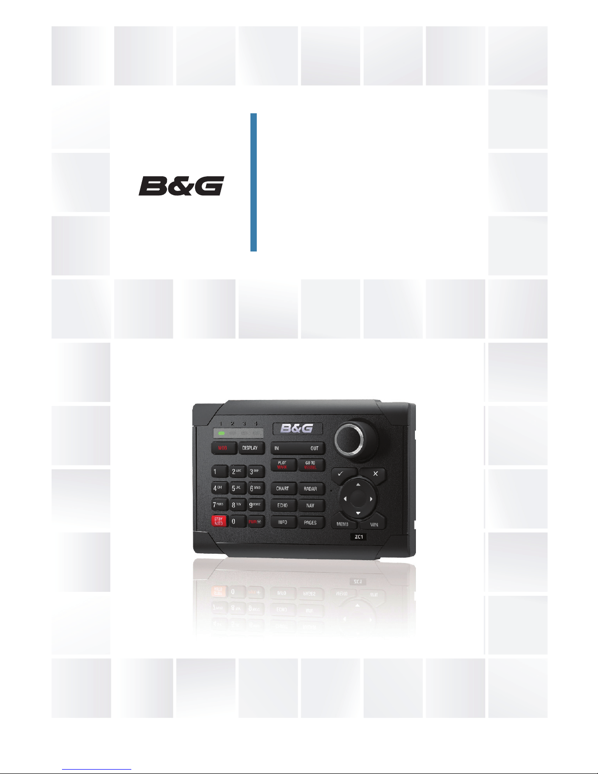
EN, DE, ES, FR, IT
bandg.com
ZC1
User Guide
Page 2
2 |
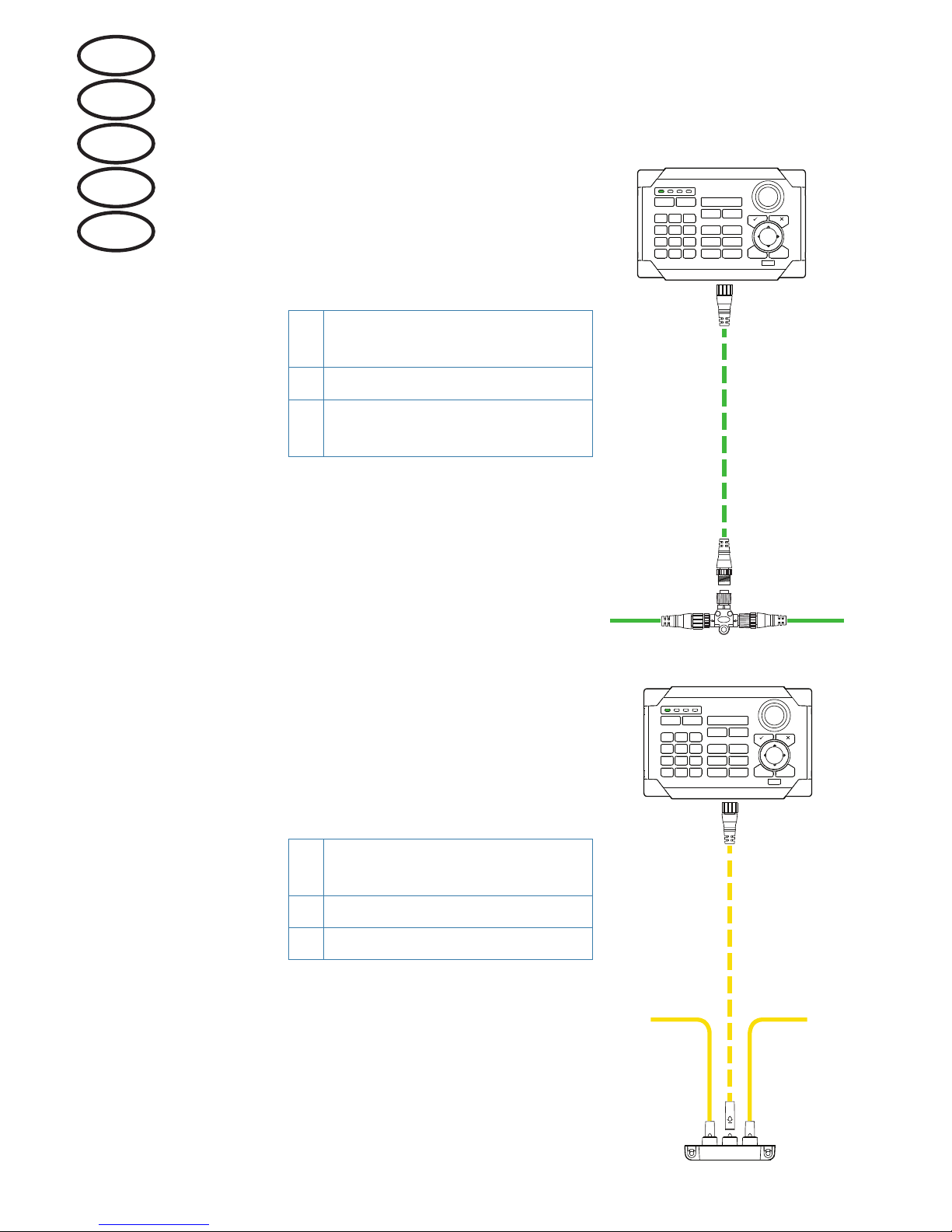
Wiring / Verkabelung / Cableado / Câblage /
Cablaggio
Micro-C (NMEA 2000)
A
Female-Male Micro-C drop
cable
B Micro-C T-connector
C
Micro-C (NMEA 2000)
backbone
SimNet
D
Micro-C to SimNet adapter
cable
E SimNet Multi-joiner
F SimNet backbone
1 2 3 4
1 2 3 4
C C
A
B
1 2 3 4
D
F F
E
EN
DE
ES
FR
IT
Page 3
| 3
Technical specications / Technische
Daten / Especicaciones técnicas /
Caractéristiques techniques /
Speciche tecniche
¼ Note: For updated technical specifications, compliance and
certifications, refer to our website.
¼ Hinweis: Die aktuellen Versionen der technischen Daten,
Konformitätserklärungen und Zertifikate finden Sie auf unserer
Website.
¼ Nota: Consulte nuestro sitio web para acceder a la versión
actualizada de las especificaciones técnicas, la documentación sobre
conformidad y las certificaciones.
¼ Remarque: pour consulter les mises à jour des caractéristiques
techniques, compatibilités et certifications, consultez notre site Web.
¼ Nota: per consultare certificazioni, specifiche tecniche e documenti
di conformità aggiornati fare riferimento al nostro sito Web.
Weight & Dimensions
Dimensions 107 mm x 160 mm (H x W)
4.2 in x 6.3 in (H x W)
Weight 0.3 kg (0.7 lbs)
Power
Power supply 12 V DC (Micro-C / SimNet)
Current consumption <250 mA : 5 LEN
Data
Micro-C Rear connector (Male Micro-C)
Network NMEA 2000 / Optional SimNet to
Micro-C cable
Technical
Keypad beeper >80 dBA @ 0.5 m
Backlight White or Red
Environmental protection IPX6
EN
DE
ES
FR
IT
Page 4
4 |
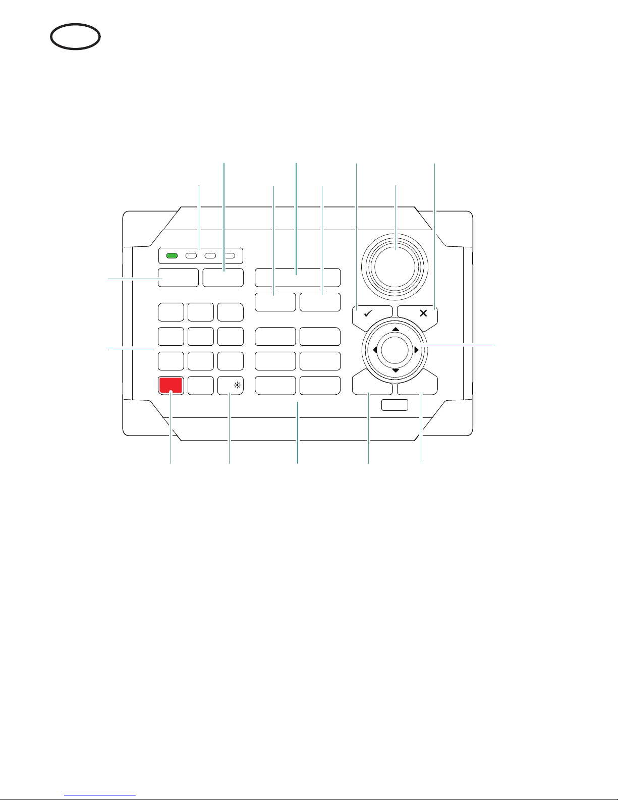
Front panel and keys
MARK
VESSEL
STBY
AUTO
PWR
MOB
4
5 7
8
2
3
6
9
10
1112131415
1
16
PLOT GO TO
MENU WIN
1
1 2 3 4
3
6
7
PQRS
8
TUV
9
WXYZ
MNO
5
JKL
2
ABC DEF
GHI
4
0
OUT
IN
RADARCHART
ECHO NAV
INFO PAGES
DISPLAY
EN
Page 5

| 5
No. Description
1
MOB (Man Overboard) key. A long press positions a Man Over Board waypoint at
the vessel’s current position
2 Unit under command LEDs. Indicates which display the ZC1 is controlling
3
DISPLAY key. Use short presses to toggle through displays that are configured for
ZC1 control. A long press turns the ZC1 to configuration mode.
4
PLOT/MARK key. A short press activates the Plot menu, a long press positions a
waypoint at the vessel position
5 IN / OUT key. Zooms radar, echosounder and chart panels. Adjusts audio volume
6
GOTO/VESSEL key. A short press activates the Goto menu, a long press centers
the chart to vessel position
7
P key. Activates/confirms current selection
8 Rotary knob. The function of the knob is depending on active context
9 X key. Cancels changes and returns to previous menu level
10
Cursor keypad. Used to move the cursor on the display, and to maneuver in the
menu system
11
WIN key, used on multiple panels pages. A short press toggles between the
panels, a long press expands active panel to a full page panel and back again
12
MENU key. A single press displays the menu for the active panel/overlay. A second
press displays the settings menu
13
Direct Access Keys (DAK). Provide direct access to a page. Repeated presses of
each DAK cycles through all pages that relate to the DAK
14
Power / Brightness key. A short press activates the dialog used to adjust
brightness, change day / night illumination and set the unit in standby mode
15
STBY/AUTO key. Switches the system to Standby mode if the autopilot is active.
Displays the autopilot dialog if the autopilot is not active
16 Alpha numeric keypad used for entering numbers and text in dialog boxes
EN
Page 6
6 |
Conguring the ZC1
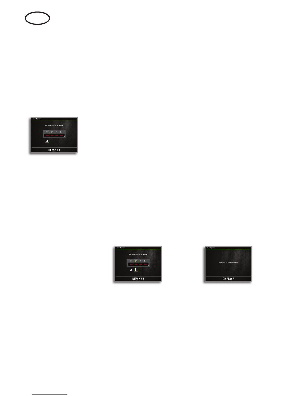
The ZC1 can control up to 4 compatible MFDs (Multi Function
Displays). Refer to your MFD’s website for more information.
From the factory the ZC1 is not assigned to control any MFD. It will
not be responsive until it has been assigned to control an MFD on
the network.
1. Turn ON all MFDs that are to be configured for ZC1 control
2. Press and hold the DISPLAY key on ZC1 for 5 seconds to enter ZC1
configuration mode
- All LEDS on the ZC1 turn red to indicate that the ZC1 is in
configuration mode
3. Press the DISPLAY key until the MFD to be assigned shows the
active assignment dialog
¼ Note: The MFDs are identified with letters for assignment purpose.
These letters are random and not in any particular order.
4. Press the 1, 2, 3 or 4 key on the ZC1 to assign active MFD to LED
position 1, 2, 3 or 4 respectively
- It is logical to assign LED(s) 1 through 4 (left to right) to units
moving from left to right.
5. Press the DISPLAY key until the next MFD to be assigned shows
the active assignment dialog
- Already assigned MFDs will now show the passive assignment
dialog
Active MFD Passive MFD
6. Repeat step 3 and 4 until all MFDs are assigned to a LED
7. Press the X key to save your settings and return to normal operation.
EN
Page 7
| 7
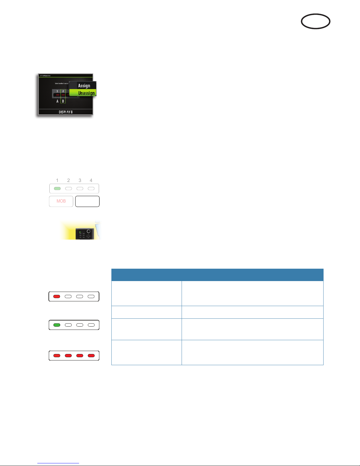
Unassigning an MFD from an ZC1
1. Press and hold the DISPLAY key for 5 seconds to enter ZC1
configuration mode
2. Use the arrow keys or the rotary knob to select which MFD that is to
be unassigned
- Selected MFD is identified with a red border
3. Press the MENU key to display the menu, and select the unassign
option
4. Press the X key to save your settings and return to normal operation.
Conguring the next ZC1
Press and hold the DISPLAY key for 1 second to take command of
another ZC1 in configuration mode.
Selecting which MFD to control
Press the DISPLAY key to toggle through the LEDs.
Once a LED has green steady light the ZC1 is in control of the MFD
assigned to that LED.
The MFD controlled by ZC1 has a small ZC1 icon on the screen.
ZC1 LEDs
Color/Status Description
1 2 3 4
1 2 3 4
Red - steady
No MFD assigned to the LED, or the MFD
assigned to the LED is powered OFF
1 2 3 4
1 2 3 4
1 2 3 4
Green - flashing MFD assigned to the LED is powering up
Green - steady
MFD assigned to the LED is ON and ready
for ZC1 control
1 2 3 4
All LEDs
Red - steady
The ZC1 is in configuration mode
MOB
123
4
DISPLAY
EN
Page 8

8 |
Vorderseite und Tasten
MARK
VESSEL
STBY
AUTO
PWR
MOB
4
5 7
8
2
3
6
9
10
1112131415
1
16
PLOT GO TO
MENU WIN
1
1 2 3 4
3
6
7
PQRS
8
TUV
9
WXYZ
MNO
5
JKL
2
ABC DEF
GHI
4
0
OUT
IN
RADARCHART
ECHO NAV
INFO PAGES
DISPLAY
DE
Page 9

| 9
Nr. Beschreibung
1
Taste "MOB" (Mann über Bord). Bei längerer Betätigung der Taste wird ein MOBWegpunkt an der Schiffsposition gesetzt.
2
LEDs für das derzeit kontrollierte Gerät. Kennzeichnet, welches Display vom ZC1
kontrolliert wird.
3
Taste "DISPLAY". Bei kurzer Betätigung werden die verschiedenen Displays
angezeigt, die für die ZC1-Kontrolle konfiguriert sind. Bei längerer Betätigung wird
der Displaykonfigurationsmodus des ZC1 aktiviert.
4
Taste "PLOT/MARK". Indem Sie die Taste kurz drücken, wird das Menü "Plot"
aktiviert. Wenn Sie die Taste länger gedrückt halten, wird ein Wegpunkt an der
Schiffsposition gesetzt.
5
Taste "IN/OUT". Vergrößert bzw. verkleinert die Radar-, Echolot- und
Kartenbereiche. Passt die Lautstärke an.
6
Taste "GOTO/VESSEL". Indem Sie die Taste kurz drücken, wird das Menü "Goto"
aktiviert. Wenn Sie die Taste gedrückt halten, wird die Karte um die Schiffsposition
zentriert.
7
Taste "
P". Aktiviert/bestätigt die aktuelle Auswahl.
8 Drehknopf. Die Funktion des Knopfes ist vom aktiven Inhalt abhängig.
9 Taste "X". Verwirft Änderungen und kehrt zur vorherigen Menüebene zurück.
10
Cursor-Tastenfeld. Dient zum Bewegen des Cursors auf dem Display und zum
Navigieren durch die Menüs.
11
Taste "WIN" – Verwendung in verschiedenen Bereichen/Seiten. Bei kurzer
Betätigung wird zwischen den Bereichen gewechselt. Bei längerer Betätigung
wird der aktive Bereich zu einem Vollbildbereich maximiert und wieder minimiert.
12
Taste "MENU". Bei einmaliger Betätigung wird das Menü für den aktiven Bereich
bzw. die Einblendung angezeigt. Bei einer zweiten Betätigung wird das
Einstellungsmenü aktiviert.
13
Direktaufruf-Tasten. Ermöglichen den direkten Aufruf einer Seite. Bei wiederholter
Betätigung der jeweiligen Direktaufruf-Tasten werden die verschiedenen Seiten
im Zusammenhang mit den entsprechenden Direktaufruf-Tasten angezeigt.
14
Einschalt-/Helligkeitstaste. Bei kurzer Betätigung wird das Dialogfeld zum
Anpassen der Helligkeit, zum Ändern der Tag- und Nachtbeleuchtung und zum
Aktivieren des Standby-Modus des Geräts aktiviert.
15
Taste "STBY/AUTO". Aktiviert den Standby-Modus des Geräts, wenn der Autopilot
aktiv ist. Zeigt das Autopilot-Dialogfeld an, wenn der Autopilot nicht aktiv ist.
16 Alphanumerisches Tastenfeld zur Eingabe von Zahlen und Text in Dialogfeldern.
DE
Page 10

10 |
Kongurieren des ZC1
Das ZC1 kann bis zu 4 kompatible MFDs (Multifunktionsdisplays)
kontrollieren. Weitere Informationen finden Sie auf der Website Ihres
MFDs.
Werkseitig ist das ZC1 nicht zur Kontrolle eines MFDs konfiguriert.
Es muss erst einem MFD im Netzwerk zugewiesen werden, bevor es
dieses kontrollieren kann.
1. Schalten Sie alle MFDs ein, die für die ZC1-Kontrolle konfiguriert sind
2. Halten Sie am 5 Sekunden lang die Taste DISPLAY gedrückt, um den
ZC1-Konfigurationsmodus aufzurufen
- Alle LEDs am ZC1 leuchten rot, um anzuzeigen, dass sich das ZC1
im Konfigurationsmodus befindet
3. Drücken Sie die Taste DISPLAY, bis auf dem zuzuweisenden MFD
das Dialogfeld für die aktive Zuweisung angezeigt wird
¼ Hinweis: Die MFDs werden zum Zweck der Zuweisung mit
Buchstaben identifiziert. Diese Buchstaben werden zufällig und in
beliebiger Reihenfolge ausgewählt
4. Drücken Sie auf dem die Taste 1, 2, 3 oder 4, um dem aktiven MFD
die LED-Position 1, 2, 3 oder 4 zuzuweisen
- Es bietet sich an, den LEDs 1 bis 4 (von links nach rechts) die
Geräte von links nach rechts zuzuweisen
5. Drücken Sie die Taste DISPLAY, bis auf dem nächsten
zuzuweisenden MFD das Dialogfeld für die aktive Zuweisung
angezeigt wird
- Auf bereits zugewiesenen MFDs wird jetzt das Dialogfeld für die
passive Zuweisung angezeigt
Aktives MFD Passives MFD
6. Wiederholen Sie die Schritte 3 und 4, bis alle MFDs einer LED
zugewiesen sind
7. Drücken Sie die Taste X, um die Einstellungen zu speichern und zum
Normalbetrieb zurückzukehren.
DE
Page 11

| 11
Aufheben der Zuweisung von MFDs von einem ZC1
1. Halten Sie 5 Sekunden lang die Taste DISPLAY gedrückt, um den
ZC1-Konfigurationsmodus aufzurufen.
2. Wählen Sie mithilfe der Pfeiltasten oder des Drehknopfes aus, für
welches MFD die Zuweisung aufgehoben werden soll.
- Das ausgewählte MFD wird durch eine rote Umrandung
gekennzeichnet.
3. Drücken Sie die Taste MENU, um das Menü anzuzeigen und die
Option zum Aufheben der Zuweisung auszuwählen.
4. Drücken Sie die Taste X, um die Einstellungen zu speichern und zum
Normalbetrieb zurückzukehren.
Kongurieren des nächsten ZC1
Halten Sie 1 Sekunde lang die Taste DISPLAY gedrückt, um das
Kommando eines weiteren ZC1 im Konfigurationsmodus zu
übernehmen.
Auswählen des zu kontrollierenden MFDs
Drücken Sie die Taste DISPLAY, um zwischen den LEDs zu
wechseln.
Wenn eine LED grün leuchtet, kontrolliert das ZC1 das MFD, das
dieser LED zugewiesen ist.
Auf dem von einem ZC1 kontrollierten MFD wird auf dem
Bildschirm ein kleines ZC1-Symbol angezeigt.
LEDs des ZC1
Farbe/Status Beschreibung
1 2 3 4
1 2 3 4
Rot – leuchtet
Der LED ist kein MFD zugewiesen, oder
das MFD, das der LED zugewiesen ist, ist
ausgeschaltet.
1 2 3 4
1 2 3 4
1 2 3 4
Grün – blinkt
Das MFD, das der LED zugewiesen ist,
schaltet sich ein.
Grün – leuchtet
Das MFD, das der LED zugewiesen ist,
ist eingeschaltet und kann vom ZC1
kontrolliert werden.
1 2 3 4
Alle LEDs
Rot – leuchten
Das ZC1 befindet sich im
Konfigurationsmodus.
MOB
123
4
DISPLAY
DE
Page 12

12 |
Teclas y panel frontal
MARK
VESSEL
STBY
AUTO
PWR
MOB
4
5 7
8
2
3
6
9
10
1112131415
1
16
PLOT GO TO
MENU WIN
1
1 2 3 4
3
6
7
PQRS
8
TUV
9
WXYZ
MNO
5
JKL
2
ABC DEF
GHI
4
0
OUT
IN
RADARCHART
ECHO NAV
INFO PAGES
DISPLAY
ES
Page 13

| 13
Nro. Descripción
1
Tecla MOB (Hombre al agua). Una pulsación larga coloca un waypoint de Hombre
al agua en la posición actual de la embarcación.
2 Indicadores LED de control de la unidad. Indica qué pantalla controla ZC1.
3
Tecla DISPLAY. Use pulsaciones breves para alternar entre pantallas configuradas
para el control de ZC1. Una pulsación larga activa el modo de configuración de
pantalla de ZC1.
4
Tecla PLOT/MARK. Una pulsación breve activa el menú Plotear. Una pulsación
larga coloca un waypoint en la posición actual de la embarcación.
5
Tecla IN / OUT. Activa el modo de zoom sobre los paneles de radar, sonda y carta.
Ajusta el volumen de audio.
6
Tecla GOTO/VESSEL. Una pulsación breve activa el menú Ir a. Una pulsación larga
centra la carta en la posición de la embarcación.
7
Tecla
P. Activa o confirma la selección actual.
8 Botón giratorio. La función del botón depende del contexto activo.
9 Tecla X. Cancela los cambios y vuelve al nivel de menú anterior.
10
Teclas de dirección. Usadas para mover el cursor por la pantalla y para desplazarse
por el sistema de menús.
11
Tecla WIN, usada en páginas de múltiples ventanas. Una pulsación corta permite
cambiar entre las ventanas, una pulsación larga expande la ventana activa a una
ventana de página completa y viceversa.
12
Tecla MENU. Una pulsación única muestra el menú para la ventana/superposición
activas. Una segunda pulsación muestra el menú de ajustes.
13
Teclas de acceso directo (TAD). Brindan acceso directo a una página. Si se pulsa
repetidamente cada TAD, se va pasando por todas las páginas relacionadas con
estas.
14
Tecla de encendido/brillo. Una pulsación breve activa el cuadro de diálogo usado
para ajustar el brillo, cambiar la iluminación día/noche y establecer la unidad en el
modo En espera.
15
Tecla STBY/AUTO. Cambia el sistema al modo En espera si el piloto automático
está activo. Muestra el cuadro de diálogo del piloto automático si el piloto
automático no está activo.
16
Teclado alfanumérico usado para introducir números y texto en los cuadros de
diálogo.
ES
Page 14

14 |
ES
Conguración de ZC1
ZC1 puede controlar hasta 4 pantallas multifunción compatibles.
Consulte el sitio web de su pantalla multifunción para obtener más
información.
ZC1 no viene asignado de fábrica para controlar ninguna pantalla
multifunción. No responderá hasta que se asigne para controlar una
pantalla multifunción en la red.
1. Active todas las pantallas multifunción que se vayan a configurar
para controlar mediante ZC1
2. Mantenga pulsada la tecla DISPLAY de ZC1 durante 5 segundos
para acceder al modo de configuración de ZC1
- Todos los LED de ZC1 se iluminan en color rojo para indicar que
ZC1 se encuentra en modo de configuración
3. Pulse la tecla DISPLAY hasta que la pantalla multifunción que se va
a asignar muestre el cuadro de diálogo de asignación activo
¼ Nota: Las pantallas multifunción se identifican con letras para fines
de asignación. Las letras son aleatorias y no siguen ningún orden
concreto
4. Pulse la tecla 1, 2, 3 o 4 de ZC1 para asignar una pantalla
multifunción activa a la posición LED 1, 2, 3 o 4, respectivamente
- Resulta lógico asignar los LED 1 a 4 (de izquierda a derecha) a
unidades dispuestas de izquierda a derecha
5. Pulse la tecla DISPLAY hasta que la siguiente pantalla multifunción
que se vaya a asignar muestre el cuadro de diálogo de asignación
activa
- Las pantallas multifunción asignadas mostrarán el cuadro de
diálogo de asignación pasiva
Pantalla multifunción activa Pantalla multifunción pasiva
6. Repita los pasos 3 y 4 hasta que se hayan asignado todas las
pantallas multifunción a un LED
7. Pulse la tecla X para guardar los ajustes y volver al modo de
funcionamiento normal.
Page 15

| 15
ES
Anulación de la asignación de una pantalla multifunción de un ZC1.
1. Mantenga pulsada la tecla DISPLAY durante 5 segundos para
acceder al modo de configuración de ZC1
2. Use las teclas de flecha o el botón giratorio para seleccionar la
pantalla multifunción cuya asignación se va a anular
- La pantalla multifunción seleccionada se identifica mediante un
borde de color rojo
3. Pulse la tecla MENU para mostrar el menú y seleccione la opción
para anular la asignación
4. Pulse la tecla X para guardar los ajustes y volver al funcionamiento
normal.
Conguración del siguiente ZC1.
Mantenga pulsada la tecla DISPLAY durante 1 segundo para tomar
el control de otro ZC1 en modo de configuración.
Selección de la pantalla multifunción que
se va a controlar
Pulse la tecla DISPLAY para alternar entre los LED.
Si un LED se ilumina de color verde de forma continua, ZC1 tendrá
el control de la MFD asignada a dicho LED.
La pantalla multifunción controlada por ZC1 mostrará un pequeño
icono de ZC1 en la pantalla.
Indicadores LED de ZC1
Color/Estado Descripción
1 2 3 4
1 2 3 4
Rojo - Fijo
No se ha asignado ninguna pantalla
multifunción al LED o la pantalla
multifunción asignada al LED está apagada.
1 2 3 4
1 2 3 4
1 2 3 4
Verde - Parpadeante
La pantalla multifunción asignada al LED se
está encendiendo.
Verde - Fijo
La pantalla multifunción asignada al LED
está encendida y lista para el control de
ZC1.
1 2 3 4
Todos los LED
Rojo - Fijo
ZC1 se encuentra en modo de
configuración.
MOB
123
4
DISPLAY
Page 16

16 |
Face avant et touches
MARK
VESSEL
STBY
AUTO
PWR
MOB
4
5 7
8
2
3
6
9
10
1112131415
1
16
PLOT GO TO
MENU WIN
1
1 2 3 4
3
6
7
PQRS
8
TUV
9
WXYZ
MNO
5
JKL
2
ABC DEF
GHI
4
0
OUT
IN
RADARCHART
ECHO NAV
INFO PAGES
DISPLAY
FR
Page 17

| 17
FR
N° Description
1
Touche MOB (homme à la mer). Une pression longue place un waypoint Homme
à la mer à la position actuelle du bateau.
2 Voyants des unités sous contrôle. Indique quel écran est contrôlé par le ZC1.
3
Touche DISPLAY. De brèves pressions répétées permettent d'alterner entre
les écrans configurés pour être contrôlés par le ZC1. Une pression longue fait
basculer le ZC1 en mode Configuration d'écran.
4
Touche PLOT/MARK. Une brève pression active le menu Marque, une pression
longue place un waypoint à la position actuelle du bateau.
5
Touche IN/OUT. Effectue un zoom sur les fenêtres Radar, Sondeur et Carte. Règle
le volume audio.
6
Touche GOTO/VESSEL. Une brève pression active le menu GoTo, une pression
longue centre la carte sur la position du bateau.
7
Touche
P. Active/confirme la sélection actuelle.
8 Bouton rotatif. La fonction de ce bouton dépend du contexte actif.
9 Touche X. Annule les modifications et permet de revenir au menu précédent.
10
Touches fléchées. Permet de déplacer le curseur sur l'écran et de naviguer dans
les menus.
11
Touche WIN, utilisée sur plusieurs fenêtres. Une brève pression permet de
basculer entre les fenêtres, une pression longue permet d'afficher la fenêtre active
en plein écran ou de la réduire.
12
Touche MENU. Une seule pression affiche le menu pour la fenêtre/superposition
active. Une deuxième pression affiche le menu des réglages.
13
Touches d'accès direct (DAK). Permettent d'accéder directement à une page. En
appuyant de manière répétée sur une touche DAK, vous pouvez parcourir toutes
les pages en lien avec celle-ci.
14
Touche marche-arrêt/luminosité Une brève pression active la boîte de dialogue
permettant de régler la luminosité, de basculer entre l'éclairage diurne et
nocturne et de mettre l'unité en mode de veille.
15
Touche STBY/AUTO Bascule le système en mode de veille si le pilote automatique
est activé. Affiche la boîte de dialogue du pilote automatique si le pilote
automatique n'est pas activé.
16
Clavier alphanumérique utilisé pour saisir des nombres et du texte dans les boîtes
de dialogue.
Page 18

18 |
FR
Conguration du ZC1
Le ZC1 peut contrôler jusqu’à 4 écrans multifonctions compatibles.
Reportez-vous au site Web de votre écran multifonction pour plus
d’informations.
À la sortie d’usine, aucun écran multifonction n’est associé au ZC1.
Il ne répondra pas tant qu’il n’aura pas été associé au contrôle d’un
écran multifonction sur le réseau.
1. Allumez tous les écrans multifonctions devant être configurés pour
être contrôlés par le ZC1
2. Appuyez sur la touche DISPLAY du ZC1 et maintenez-la enfoncée
pendant 5 secondes pour accéder au mode Configuration du ZC1
- Tous les voyants du ZC1 s’allument en rouge pour indiquer que
le ZC1 est en mode Configuration
3. Appuyez sur la touche DISPLAY jusqu’à ce que l’écran
multifonction à associer affiche la boîte de dialogue d’association
active
¼ Remarque: les écrans multifonctions à associer sont identifiés par
des lettres. Ces lettres sont attribuées de manière aléatoire et ne
suivent pas d’ordre particulier
4. Appuyez sur la touche 1, 2, 3 ou 4 du ZC1 pour associer l’écran
multifonction actif au voyant 1, 2, 3 ou 4
- Il est logique d’associer les voyants 1 à 4 (de gauche à droite) à
des unités allant de gauche à droite
5. Appuyez sur la touche DISPLAY jusqu’à ce que le prochain écran
multifonctions à associer affiche la boîte de dialogue d’association
active
- Les écrans multifonctions déjà associés affichent maintenant la
version passive de la boîte de dialogue d’association
Écran multifonction actif Écran multifonction passif
6. Répétez les étapes 3 et 4 jusqu’à ce que tous les écrans
multifonctions soient associés à un voyant
7. Appuyez sur la touche X pour enregistrer vos réglages et revenir au
fonctionnement normal.
Page 19

| 19
FR
Dissociation d’un écran multifonction sur un ZC1
1. Appuyez sur la touche DISPLAY et maintenez-la enfoncée pendant
5 secondes pour accéder au mode Configuration du ZC1.
2. Utilisez les touches fléchées ou le bouton rotatif pour sélectionner
l’écran multifonction à dissocier
- L’écran multifonction sélectionné est identifié par une bordure
rouge
3. Appuyez sur la touche MENU pour afficher le menu, puis
sélectionnez l’option de dissociation
4. Appuyez sur la touche X pour enregistrer vos réglages et revenir au
fonctionnement normal.
Conguration du prochain ZC1
Appuyez sur la touche DISPLAY et maintenez-la enfoncée pendant
1 seconde pour prendre le contrôle d’un autre ZC1 en mode
Configuration.
Sélection d’un écran multifonction à
contrôler
Appuyez sur la touche DISPLAY pour basculer entre les voyants.
Lorsqu’un voyant s’allume en vert et cesse de clignoter, cela signifie
que le ZC1 contrôle l’écran multifonction associé à ce voyant.
L’écran multifonction contrôlé par un ZC1 affiche une petite icône
ZC1 sur l’écran.
Voyants ZC1
Couleur/État Description
1 2 3 4
1 2 3 4
Rouge - fixe
Aucun écran multifonction n'est associé à
ce voyant, ou l'écran associé à ce voyant
est éteint.
1 2 3 4
1 2 3 4
1 2 3 4
Vert - clignotant
L'écran multifonction associé à ce voyant
est en cours d'allumage
Vert - fixe
L'écran multifonction associé à ce voyant
est allumé et prêt à être contrôlé par le
ZC1.
1 2 3 4
Tous les voyants
Rouges - fixes
Le ZC1 est en mode Configuration.
MOB
123
4
DISPLAY
Page 20

20 |
Pannello frontale e tasti
MARK
VESSEL
STBY
AUTO
PWR
MOB
4
5 7
8
2
3
6
9
10
1112131415
1
16
PLOT GO TO
MENU WIN
1
1 2 3 4
3
6
7
PQRS
8
TUV
9
WXYZ
MNO
5
JKL
2
ABC DEF
GHI
4
0
OUT
IN
RADARCHART
ECHO NAV
INFO PAGES
DISPLAY
IT
Page 21

| 21
IT
N. Descrizione
1
Tasto MOB (Man Overboard, uomo in mare). Con una pressione prolungata viene
inserito un waypoint Uomo in mare (MOB, Man Over Board) nella posizione
corrente dell'imbarcazione
2
LED dell'unità attualmente in controllo. Indica quale display l'unità ZC1 sta
controllando
3
Tasto DISPLAY. Con pressioni brevi viene alternata la visualizzazione dei display
configurati per il controllo da parte dell'unità ZC1. Con una pressione prolungata
l'unità ZC1 viene impostata in modalità di configurazione display
4
Tasto PLOT/MARK. Il menu Traccia viene attivato con una breve pressione del
tasto, mentre con una pressione prolungata si posiziona un waypoint nella
posizione dell'imbarcazione
5
Tasto IN/OUT. Aumenta/riduce l'ingrandimento dei riquadri radar, ecoscandaglio
e cartografia. Regola il volume dell'audio
6
Tasto GOTO/VESSEL. Il menu "Vai a" viene attivato con una breve pressione del
tasto, mentre con una pressione prolungata si centra la cartografia sulla posizione
dell'imbarcazione
7
Tasto
P. Attiva/conferma la selezione corrente
8 Manopola. La funzione della manopola dipende dal contesto attivo
9 Tasto X. Annulla le modifiche e torna al livello di menu precedente
10
Tastierino cursore. Utilizzato per spostare il cursore sul display e per spostarsi nel
sistema di menu
11
Tasto WIN, utilizzato in diverse pagine riquadri. Con una breve pressione si passa
da un riquadro all'altro, mentre con una pressione prolungata si espande il
riquadro attivo in un riquadro a pagina intera e viceversa
12
Tasto MENU. Con una singola pressione viene visualizzato il menu per il riquadro
o la sovrapposizione attivi. Premendo due volte viene visualizzato il menu
impostazioni
13
Tasti ad accesso diretto (TAD). Forniscono un accesso diretto ad una pagina.
Premendo ripetutamente ogni TAD si accede ciclicamente a tutte le pagine
correlate al TAD
14
Tasto di accensione/luminosità. Con una breve pressione si attiva la finestra
utilizzata per regolare la luminosità, cambiare l'illuminazione diurna/notturna e
impostare l'unità in modalità standby
15
Tasto STBY/AUTO. Imposta il sistema in modalità Standby se è attivo l'autopilota.
Visualizza la finestra di dialogo dell'autopilota se quest'ultimo non è attivo
16
Tastierino alfanumerico utilizzato per immettere numeri e testo nelle finestre di
dialogo
Page 22

22 |
IT
Congurazione dell’unità ZC1
L’unità ZC1 è in grado di controllare fino a 4 MFD (display
multifunzione) compatibili. Per ulteriori informazioni, fare riferimento
al sito Web del proprio MFD.
Per impostazione di fabbrica all’unità ZC1 non è assegnato alcun
MFD da controllare. L’unità non risponderà fino a quando non le
verrà assegnato un MFD da controllare sulla rete.
1. ACCENDERE tutti gli MFD che devono essere configurati per il
controllo da parte dell’unità ZC1
2. Tenere premuto per 5 secondi il tasto DISPLAY sull’unità ZC1 per
accedere alla modalità di configurazione di ZC1
- Tutti i LED sull’unità ZC1 diventano rossi per indicare che l’unità
ZC1 è entrata in modalità di configurazione
3. Premere il tasto DISPLAY fino a quando l’MFD che deve essere
assegnato non mostra la finestra di dialogo di assegnazione attiva
¼ Nota: gli MFD vengono identificati con delle lettere a scopo
di assegnazione. Queste lettere sono casuali e non sono in un
particolare ordine
4. Premere il tasto 1, 2, 3 o 4 sull’unità ZC1 per assegnare l’MFD attivo
alla posizione LED 1, 2, 3 o 4, rispettivamente
- È logico assegnare i LED da 1 a 4 (da sinistra a destra) alle unità
spostandosi da sinistra a destra.
5. Premere il tasto DISPLAY fino a quando il successivo MFD che deve
essere assegnato non mostra la finestra di dialogo di assegnazione
attiva
- Gli MFD già assegnati ora mostreranno la finestra di dialogo di
assegnazione passiva
MFD attivo MFD passivo
6. Ripetere i passaggi 3 e 4 fino ad assegnare tutti gli MFD a un LED
7. Premere il tasto X per salvare le impostazioni e tornare al
funzionamento normale
Page 23

| 23
IT
Annullamento dell’assegnazione di un MFD a un’unità
ZC1
1. Tenere premuto il tasto DISPLAY per 5 secondi per accedere alla
modalità di configurazione di ZC1
2. Utilizzare i tasti freccia o la manopola per selezionare l’MFD la cui
assegnazione deve essere annullata
- L’MFD selezionato viene identificato con un bordo rosso
3. Premere il tasto MENU per visualizzare il menu e selezionare
l’opzione per l’annullamento dell’assegnazione
4. Premere il tasto X per salvare le impostazioni e tornare al
funzionamento normale.
Congurazione di un’altra unità ZC1
Tenere premuto il tasto DISPLAY per 1 secondo per assumere il
comando di un’altra unità ZC1 in modalità di configurazione.
Selezione dell’MFD da controllare
Premere il tasto DISPLAY per scorrere i LED.
Una volta che un LED ha una luce verde fissa, l’unità ZC1 controlla
l’MFD assegnato a tale LED.
L’MFD controllato da un’unità ZC1 ha una piccola icona ZC1
presente nella schermata.
LED dell’unità ZC1
Colore/Stato Descrizione
1 2 3 4
1 2 3 4
Rosso - fisso
Nessun MFD assegnato al LED, oppure
l'MFD assegnato al LED è SPENTO
1 2 3 4
1 2 3 4
1 2 3 4
Verde lampeggiante
L'MFD assegnato al LED si sta accendendo
Verde - fisso
L'MFD assegnato al LED è ACCESO e pronto
per il controllo da parte dell'unità ZC1
1 2 3 4
Tutti i LED
Rosso - fisso
L'unità ZC1 è in modalità di configurazione
MOB
123
4
DISPLAY
Page 24

For regulatory compliance certificates
and declarations, refer to the product
website on:
http://bandg.com/
*988-10545-001*
 Loading...