

Page 1
RADIOCOMANDO ROLLING-CODE PROGRAMMABILE
I
GB
PROGRAMMABLE ROLLING-CODE RADIO TRANSMITTER
F
RADIO COMMANDE ROLLING-CODE PROGRAMMABLE
D
PROGRAMMIERBARE FERNSTEUERUNG MIT ROLLCODE
RADIOMANDO ROLLING-CODE PROGRAMABLE
E
RADIOCOMANDO ROLLING-CODE PROGRAMÁVEL
P
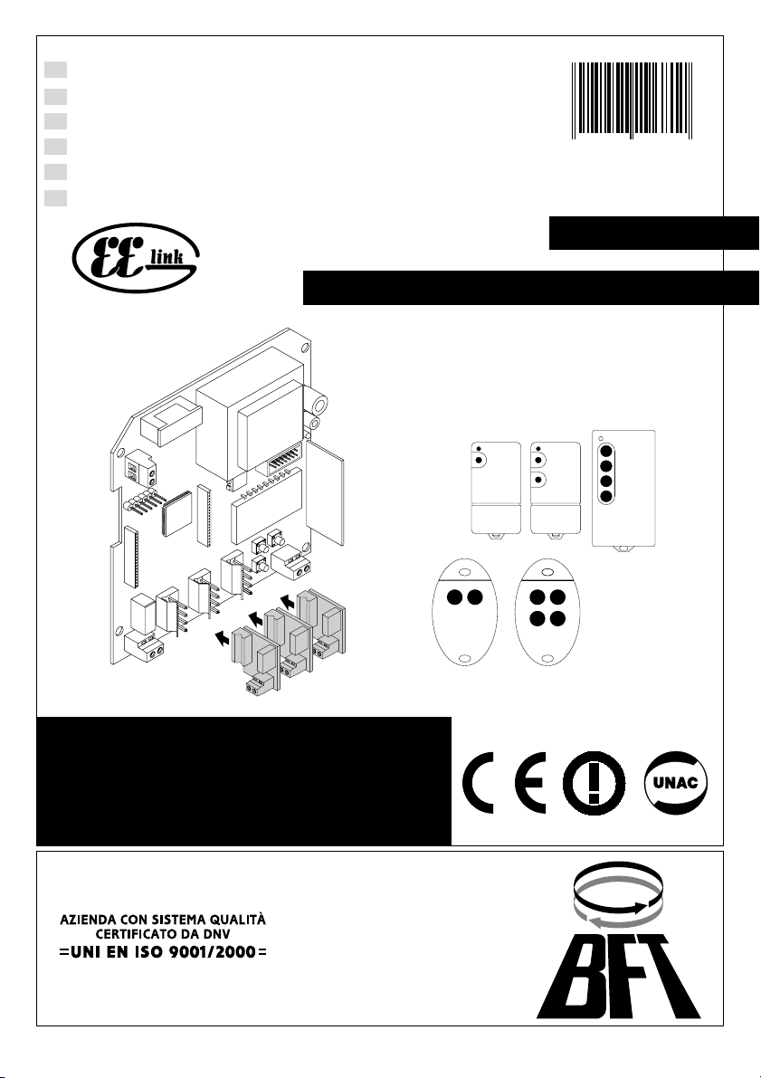
TRC 1-2-4 / MITTO 2-4 433MHz
8888
D811347 ver.03 17-07-03
8 027908 196811
RTD
ISTRUZIONI D'USO E DI INSTALLAZIONE
INSTALLATION AND USER'S MANUAL
INSTRUCTIONS D'UTILISATION ET D'INSTALLATION
INSTALLATIONS-UND GEBRAUCHSANLEITUNG
INSTRUCCIONES DE USO Y DE INSTALACION
INSTRUÇÕES DE USO E DE INSTALAÇÃO
Via Lago di Vico, 44
36015 Schio (VI)
Tel.naz. 0445 696511
Tel.int. +39 0445 696533
Fax 0445 696522
Internet: www.bft.it
E-mail: sales@bft.it
Page 2

D811347_03
2
- RTD- Ver. 03
Page 3
MANUALE D’USO ITALIANO
1) GENERALITÀ
Nel ringraziarVi per la preferenza accordata a questo prodotto, la ditta è certa che da esso otterrete le prestazioni necessarie al Vostro uso.
D811347_03
Leggete attentamente l’opuscolo ”Libretto istruzioni” che lo accompagna in quanto esso fornisce importanti indicazioni riguardanti la
sicurezza, l’installazione, l’uso e la manutenzione. Questo prodotto risponde alle norme riconosciute della tecnica e delle disposizioni relative
alla sicurezza. É conforme alle seguenti direttive europee: 89/336/CEE, 1999/5/CEE e modifiche successive.
Sistema radioricevente ad autoapprendimento, programmabile le cui principali caratteristiche sono:
• Ricevitore clonabile a 512 o 2048 codici
• Fino a 4 uscite (1 standard + 3 modulari) con riconoscimento automatico dei moduli inseriti
• Uscite configurabili come monostabile, bistabile, temporizzata, antiaggressione
• Programmazione mediante display incorporato
• Funzionamento a codice fisso e variabile.
• Compatibile con il protocollo EElink per una rapida installazione e manutenzione.
• Funzione blocco per l’inserimento automatico di gruppi di trasmettitori
• Protezione della ricevente mediante password
2) MANUTENZIONE
La manutenzione dell’impianto va fatta eseguire regolarmente da parte di personale qualificato.
Le trasmittenti MITTO sono alimentate da 2 batterie al litio da 3V (tipo CR2016).
Le trasmittenti TRC sono alimentate da una batteria alcalina da 12V.
Una diminuzione della portata della trasmittente può essere dovuta alle batterie che si stanno scaricando. Quando il led della trasmittente
lampeggia, indica che le batterie sono scariche e devono essere sostituite.
3) DEMOLIZIONE
ATTENZIONE: Avvalersi esclusivamente di personale qualificato.
L’eliminazione dei materiali va fatta rispettando le norme vigenti. Nel caso di demolizione del sistema, non esistono particolari pericoli o rischi
derivanti dai componenti stessi. È opportuno, in caso di recupero dei materiali, che vengano separati per tipologia (parti elettriche - rame alluminio - plastica - ecc.). Per lo smaltimento della batteria riferirsi alla normativa vigente.
USER’S MANUAL
1) GENERAL OUTLINE
Thank you for buying this product, our company is sure that you will be more than satisfied with the performance of the product. Read the
“Instruction Manual” supplied with this product carefully, as it provides important information about safety, installation, operation and
maintenance.This product conforms to recognised technical standards and safety regulations. It complies with the 89/336/EEC, 1999/5/CEE,
European Directive and subsequent amendments.
Programmable self-learning radio receiver system, having the following main features:
• Receiver which can be cloned with 512 or 2048 codes
• Up to 4 outputs (1 standard + 3 modular) with automatic recognition of the modules entered
• Outputs which can be configured as monostable, bistable, timed, anti-aggression
• Programming by means of incorporated display
• Operation with fixed and variable codes
• Compatible with EElink protocol for fast installation and maintenance
• Group function for automatic entry of groups of transmitters
• Protection of receiver by means of password.
2) MAINTENANCE
The maintenance of the system should only be carried out by qualified personnel regularly.
The MITTO transmitters are supplied by two 3V lithium battiers (type CR2016).
The TRC transmitters are powered by a 12V alkaline battery.
Any reduction in the transmitter capacity may be due to the batteries getting flat.
When the led of the transmitter flashes, it means that the batteries are flat and must be replaced.
3) DISPOSAL
ATTENTION: disposal should only be carried out by qualified personnel.
Materials must be disposed of in conformity with the current regulations. In case of disposal, the system components do not entail any particular
risks or danger. In case of recovered materials, these should be sorted out by type (electrical components, copper, aluminium, plastic etc.).
For battery disposal, refer to the current regulations.
ENGLISH
RTD- Ver. 03 -
3
Page 4

FRANÇAIS MANUEL D’UTILISATION
1) GÉNÉRALITÉS
Nous vous remercions pour avoir choisi ce produit. Nous sommes sûrs qu’il vous rendra le service nécessaire à vos besoins. Lire attentivement
le «Manuel d’instructions» qui accompagne ce produit puisqu’il fournit d’importantes indications concernant la sécurité, l’installation,
l’utilisation et l’entretien.
Ce produit est conforme aux normes reconnues de la technique et aux dispositions concernant la sécurité. Ce produit est conforme aux normes
reconnues de la technique et des dispositions concernant la sécurité. Il est également conforme aux directives européennes suivantes: 89/
336/CEE, 1999/5/CEE et modifications successives.
Système radio récepteur à autoapprentissage, programmable, dont les caractéristiques principales sont:
• Récepteur clonable à 512 ou 2048 codes.
• Jusqu’à 4 sorties (1 standard + 3 modulaires) avec reconnaissance automatique des modules insérés.
• Sorties configurables comme monostable, bistable, temporisée, anti-agression.
• Programmation avec écran incorporé.
• Fonctionnement à code fixe et variable.
• Compatible avec le protocole EElink pour une installation et une maintenance rapides.
• Fonction bloc pour l’introduction automatique de groupes d’émetteurs
• Protection du récepteur avec mot de passe.
2) ENTRETIEN
L’entretien de l’installation doit être effectué régulièrement de la part de personnel qualifié.
Les émetteurs MITTO sont alimentés par 2 batteries au lithium de 3V (type CR2016).
Les émetteurs TRC sont alimentés par une pile alcaline 12V.
Une réduction de la portée de l’émetteur peut être due aux batteries en train de se décharger.
Quand la led de l’émetteur clignote, cela indique que les batteries sont à plat et qu’il faut les remplacer.
3) DÉMOLITION
ATTENTION: s’adresser uniquement à du personnel qualifié. L’élimination des matériaux doit être faite en respectant les normes en
vigueur.
En cas de démolition du système, il n’existe aucun danger ou risque particulier dérivant de ses composants. En cas de récupération des
matériaux, il sera opportun de les trier selon leur genre (parties électriques - cuivre - aluminium - plastique - etc.). Pour l’élimination de la batterie,
se référer aux normes en vigueur.
D811347_03
DEUTSCH
1) ALLGEMEINES
Wir danken Ihnen, daß Sie sich für diese Anlage entschieden haben. Ganz sicher wird sie mit ihren Leistungen Ihren Ansprüchen vollauf gerecht
werden. Lesen Sie aufmerksam die Broschüre mit den “GEBRAUCHSANWEISUNGEN“ durch, die dem Produkt beiliegen. Sie enthält wichtige
Hinweise zur Sicherheit, Installation, Bedienung und Wartung der Anlage. Dieses Produkt genügt den anerkannten technischen Normen und
Sicherheitsbestimmungen. Dieses Produkt entspricht den anerkannten technischen Regeln und Sicherheitsbestimmungen. Es genügt der
Europäischen Richtlinie 89/336/EWG , 1999/5/EWG, und nachfolgenden Änderungen.
Funkempfangsanlage mit Selbstlerntechnik, programmierbar, mit folgenden Merkmalen:
• Klonierbarer Empfänger mit 512 oder 2048 Codes
• Bis zu 4 ausgänge (1 standard + 3 modular) mit automatischen Erkennung der einbezogenen Module.
• Ausgänge konfigurierbar als monostabil, bistabil, zeitgeschaltet, Aggressionssicherung.
• Programmierung am eingebauten Display.
• Betrieb mit festem und variablem Code.
• Kompatibel mit dem Protokoll EElink für eine schnelle Installation und Wartung.
• Funktion für das automatische blockweise Einfügen von Sendergruppen
• Paßwortschutz des Empfängers.
2) WARTUNG
Die Anlagenwartung ist regelmäßig von Fachleuten vorzunehmen.
Die Sender MITTO werden von 2 Litiumbatterien mit 3 V gespeist (Typ CR2016).Die Handsender TRC werden von einer 12v Alkaline Batterie
betrieben. Wenn die Reichweite des Senders abnimmt, kann es sein, daß die Batterien fast leer sind. Blinkt die LED des Senders, sind die
Batterien leer und müssen erneuert werden.
3) ENTSORGUNG
ACHTUNG: Diese Tätigkeit ist fachkundigen Personen vorbehalten.
Die Materialien sind unter Beachtung der geltenden Vorschriften zu entsorgen. Bei der Entsorgung des Systems bestehen keine besonderen,
von den Komponenten ausgehenden Gefahren oder Risiken. Es ist sinnvoll, nach Materialarten zu sortieren und die Stoffe einer getrennten
Entsorgung zuzuführen (Elektrische Komponenten - Kupfer - Aluminium - Plastik - usw.). Bei der Batterieentsorgung sind die geltenden
Vorschriften zu beachten.
4
- RTD- Ver. 03
BEDIENUNGSANLEITUNG
Page 5

MANUAL DE USO
1) GENERALIDADES
Al agradecerle la preferencia que ha manifestado por este producto, la empresa está segura de que de él obtendrá las prestaciones necesarias
D811347_03
para sus exigencias. Lea atentamente el “Manual de Instrucciones” que lo acompaña, pues proporciona importantes indicaciones referentes
a la seguridad, la instalación, el uso y el mantenimiento. Este producto responde a las normas reconocidas de la técnica y a las disposiciones
relativas a la seguridad, y es conforme a las siguientes directivas europeas: 89/336/CEE, 1999/5/CEE y modificaciones sucesivas.
Sistema radiorreceptor con función de autoaprendizaje, programable, cuyas principales características son:
• Receptor clonable de 512 ó 2048 códigos.
• Hasta 4 salidas (1 standard + 3 modulares) con reconocimiento automático de los módulos introducidos.
• Salidas configurables como monoestable, biestable, temporizada, antiagresión.
• Programación mediante display incorporado.
• Funcionamiento con código fijo y variable.
• Compatible con el protocolo EElink, para agilizar la instalación y el mantenimiento.
• Función Bloque para la introducción automática de grupos de transmisores.
• Protección del receptor mediante contraseña.
2) MANTENIMIENTO
El mantenimiento de la instalación debe ser realizado, con regularidad, por personal cualificado.
Los transmisores se alimentan mediante dos baterías al litio de 3V (tipo CR2016).
Los transmisores TRC están alimentados por una batería Alcalina de 12V.
Una disminución de la capacidad del transmisor puede deberse a las baterías que se están descargando.
Cuando el led del transm isor está parpadeando, indica que las baterías se encuentran descargadas y que deben sustituirse.
3) DEMOLICION
ATENCION: Hay que servirse exclusivamente de personal cualificado. La eliminación de los materiales debe hacerse respetando las
normas vigentes. En el caso de demolición del sistema, no existen particulares peligros o riesgos que deriven de los componentes. Es
conveniente, en caso de recuperación de los materiales, que éstos se separen por tipos (partes eléctricas, cobre, aluminio, plástico, etc.). Por
lo que respecta a la eliminación de la batería, hay que respetar la normativa vigente.
ESPAÑOL
MANUAL PARA DE USO
1) GENERALIDADES
Agradecendolhe pela preferência dada a este produto, a Empresa tem a certeza que do mesmo obterá as prestações necessárias para o uso
que entende fazer. Leia atentamente o “Manual de instruções “que acompanha este produto, pois que esse fornece indicações importantes
respeitantes a segurança, a instalação, a utilização e a manutenção. Este produto responde às normas reconhecidas pela técnica e pelas
disposições relativas à segurança.
Este produto responde às normas reconhecidas da técnica e das disposições relativas à segurança. Está em conformidade com as seguintes
directivas europeias: 89/336/CEE, 1999/5/CEE e modificações sucessivas.
Sistema radiorreceptor de autoaprendizagem, programável, cujas características principais são:
• Receptor clonável com 512 ou 2048 códigos
• Até 4 saídas (1 standard + 3 modulares) com reconhecimento automático dos módulos inseridos.
• Saídas configuráveis como monoestável, biestável, temporizada, anti-agressão.
• Programação por meio de visor incorporado.
• Funcionamento com código fixo e variável.
• Compatível com o protocolo EElink para uma rápida instalação e manutenção.
• Função bloco para a inserção automática de grupos de transmissores
• Protecção do receptor por meio de password
2) MANUTENÇÃO
A manutenção da instalação deve ser executada periodicamente por pessoal qualificado.
Os transmissores são alimentados por 2 baterias de lítio de 3V (tipo CR2016).
Os emissores TRC são alimentados por uma bateria alcalina de 12V.
Uma diminuição do alcance do transmissor pode ser devida ao facto que as baterias se estão a descarregar.
Quando o led do transmissor pisca, indica que as baterias estão descarregadas e devem ser substituídas.
3) DESTRUIÇÃO
ATENÇÃO: Servir-se exclusivamente de pessoal qualificado. A eliminação dos materiais deve ser feita respeitando-se as normas vigentes.
No caso de destruição do sistema, não existem perigos particulares ou riscos derivantes dos próprios componentes. No caso de recuperação
dos materiais é oportuno, separálos por tipo (partes eléctricas - cobre - alumínio - plástico - etc.). Para a eliminação da bateria referir-se à norma
vigente.
PORTUGUÊS
RTD- Ver. 03 -
5
Page 6

ITALIANO
MANUALE PER L’INSTALLAZIONE
Nel ringraziarVi per la preferenza accordata a questo prodotto, la ditta
è certa che da esso otterrete le prestazioni necessarie al Vostro uso.
Leggete attentamente l’opuscolo “Avvertenze” ed il “Libretto istru-
zioni” che accompagnano questo prodotto in quanto forniscono
importanti indicazioni riguardanti la sicurezza, l’installazione, l’uso e la
manutenzione. Questo prodotto risponde alle norme riconosciute
della tecnica e della disposizioni relative alla sicurezza. Confermiamo
che è conforme alle seguenti direttive europee: 89/336/CEE, 73/23/
CEE (e loro modifiche successive).
SICUREZZA GENERALE
ATTENZIONE! Una installazione errata o un uso improprio del
prodotto, può creare danni a persone, animali o cose.
• Leggete attentamente l’opuscolo ”Avvertenze” ed il ”Libretto
istruzioni” che accompagnano questo prodotto, in quanto forni-
scono importanti indicazioni riguardanti la sicurezza, l’installazione, l’uso e la manutenzione.
• Smaltire i materiali di imballo (plastica, cartone, polistirolo, ecc.)
secondo quanto previsto dalle norme vigenti. Non lasciare buste
di nylon e polistirolo a portata dei bambini.
• Conservare le istruzioni per allegarle al fascicolo tecnico e per
consultazioni future.
• Questo prodotto è stato progettato e costruito esclusivamente per
l’utilizzo indicato in questa documentazione. Usi non indicati in
questa documentazione potrebbero essere fonte di danni al
prodotto e fonte di pericolo.
• La Ditta declina qualsiasi responsabilità derivante dall’uso improprio o diverso da quello per cui è destinato ed indicato nella
presente documentazione.
• Non installare il prodotto in atmosfera esplosiva.
• Gli elementi costruttivi della macchina devono essere in accordo
con le seguenti Direttive Europee: 89/336/CEE, 1999/5/CEE e
modifiche successive. Per tutti i Paesi extra CEE, oltre alle norme
nazionali vigenti, per un buon livello di sicurezza è opportuno
rispettare anche le norme sopracitate.
• La Ditta declina qualsiasi responsabilità dall’inosservanza della
Buona Tecnica nella costruzione delle chiusure (porte, cancelli,
ecc.), nonché dalle deformazioni che potrebbero verificarsi durante l’uso.
• L’installazione deve essere in accordo con quanto previsto dalle
Direttive Europee: 89/336/CEE, 1999/5/CEE e modifiche successive.
• Togliere l’alimentazione elettrica, prima di qualsiasi intervento
sull’impianto. Scollegare anche eventuali batterie tampone se
presenti.
• Prevedere sulla rete di alimentazione dell’automazione, un interruttore o un magnetotermico onnipolare con distanza di apertura
dei contatti uguale o superiore a 3mm.
• Verificare che a monte della rete di alimentazione, vi sia un
interruttore differenziale con soglia da 0.03A.
• Verificare se l’impianto di terra è realizzato correttamente: collegare tutte le parti metalliche della chiusura (porte, cancelli, ecc.)
e tutti i componenti dell’impianto provvisti di morsetto di terra.
• Applicare tutti i dispositivi di sicurezza (fotocellule, coste sensibili,
ecc.) necessari a proteggere l’area da pericoli di schiacciamento,
convogliamento, cesoiamento.
• Applicare almeno un dispositivo di segnalazione luminosa (lampeggiante) in posizione visibile, fissare alla struttura un cartello di
Attenzione.
• La Ditta declina ogni responsabilità ai fini della sicurezza e del
buon funzionamento dell’automazione se vengono impiegati componenti di altri produttori.
• Usare esclusivamente parti originali per qualsiasi manutenzione
o riparazione.
• Non eseguire alcuna modifica ai componenti dell’automazione se
non espressamente autorizzata dalla Ditta.
• Istruire l’utilizzatore dell’impianto per quanto riguarda i sistemi di
comando applicati e l’esecuzione dell’apertura manuale in caso di
emergenza.
• Non permettere a persone e bambini di sostare nell’area d’azione
dell’automazione.
• Non lasciare radiocomandi o altri dispositivi di comando alla
portata dei bambini onde evitare azionamenti involontari dell’automazione.
6
- RTD- Ver. 03
• L’utilizzatore deve evitare qualsiasi tentativo di intervento o riparazione dell’automazione e rivolgersi solo a personale qualificato.
• Tutto quello che non è espressamente previsto in queste istruzioni, non è permesso.
1) GENERALITÀ
Sistema radioricevente ad autoapprendimento, programmabile le cui
principali caratteristiche sono:
• Ricevitore clonabile a 512 o 2048 codici
• Fino a 4 uscite (1 standard + 3 modulari) con riconoscimento
automatico dei moduli inseriti
• Uscite configurabili come monostabile, bistabile, temporizzata,
antiaggressione.
• Programmazione mediante display incorporato
• Funzionamento a codice fisso e variabile.
• Compatibile con il protocollo EElink per una rapida installazione
e manutenzione.
• Funzione blocco per l’inserimento automatico di gruppi di trasmettitori
• Protezione della ricevente mediante password
Il ricevitore RTD unisce alle caratteristiche di estrema sicurezza alla
copiatura della codifica a codice variabile (rolling code), la praticità di
poter effettuare, grazie ad un esclusivo sistema, operazioni di
“clonazione” di trasmettitori.
Clonare un trasmettitore significa generare un trasmettitore in grado di
inserirsi automaticamente nella lista dei trasmettitori memorizzati nel
ricevitore aggiungendosi o sostituendo un particolare trasmettitore.
Sarà quindi possibile programmare a distanza e senza intervenire sul
ricevitore un gran numero di trasmettitori in aggiunta o in sostituzione
di trasmettitori che, per esempio, siano stati smarriti.
La clonazione per sostituzione consente di creare un nuovo trasmettitore che prende il posto nel ricevitore di un trasmettitore precedentemente memorizzato, in questo modo sarà possibile rimuovere dalla
memoria e rendere non più utilizzabile un trasmettitore.
Quando la sicurezza della codifica non sia determinante, il ricevitore
RTD permette di effettuare la clonazione in aggiunta a codice fisso
che, rinunciando al codice variabile, permette comunque di avere una
codifica con un elevato numero di combinazioni, mantenendo la
possibilità di “copiare” qualsiasi trasmettitore già programmato.
L’utilizzo di cloni quando vi sia più di un ricevitore (come nel caso delle
comunità) e specialmente quando vi sia da distinguere tra cloni da
aggiungere o sostituire in ricevitori particolari o collettivi, potrebbe
risultare assai difficile; il sistema di clonazione per collettività del
ricevitore RTD risulta particolarmente semplice e risolve la memorizzazione dei cloni fino a 250 ricevitori particolari.
Il controllo del varco viene gestito da un’uscita con contatto N.O.; nel
caso si renda necessario è possibile incrementare il numero di uscite
mediante appositi moduli opzionali MOP, che consentono di ottenere
un massimo di 4 canali di uscita, configurabili in modo indipendente.
2) DATI TECNICI
2.1) Ricevitore
Alimentazione: ................................................. 230V ±10%50Hz (*)
Frequenza: ....................................................................... 433.92MHz
Temperatura di funzionamento: ...................................... -20 / +55°C
Codice a mezzo: ............................................. Algoritmo rolling-code
N°combinazioni: ................................................................... 4 miliardi
Impedenza antenna: .................................................. 50Ohm (RG58)
Dimensioni: ....................................................................... vedere fig.1
Contatto relè: .................................................................... 0,5A - 12V=
Grado di protezione: ................................................................. IP 20*
N° max radiotrasmettitori memorizzabili:
Versione ricevente N° radiotrasmettitori
RTD 512 512
RTD 2048 2048
(*) Il grado di protezione dell’involucro diviene IP55 utilizzando un
accessorio fornibile a richiesta. Utilizzare solo raccordi adatti alle
dimensioni del contenitore e al diametro del cavo.
D811347_03
Page 7

MANUALE PER L’INSTALLAZIONE
ITALIANO
2.2) Trasmettitore MITTO
Tasti : ...............................................................................Colore giallo
D811347_03
Alimentazione: ............................ 2 Pile al Litio da 3V (tipo CR2016)
Portata: .......................................................................... 50 / 100 metri
Versioni trasmettitori:
MITTO2 - bicanale, MITTO4 - quadricanale.
2.3) Trasmettitore TRC
Tasti: ............................................................................... Colore rosso
Alimentazione: ......................................................... Pila Alkalina 12V
Portata: .......................................................................... 50 / 100 metri
Versioni trasmettitori:
TRC1-monocanale, TRC2-bicanale, TRC4-quadricanale.
Accessori (opzionali):
RTD-RS
Scheda aggiuntiva per il controllo via modem della ricevente RTD.
MOP (Fig.2)
Modulo ad innesto dotato di uscita aggiuntiva contatto N.O.
3) INSTALLAZIONE
Dopo aver predisposto il passaggio dei cavi di collegamento procedere al fissaggio del supporto (fig.1), segnando i due fori utilizzando le
due asole a disposizione sul contenitore come dima. In base al
materiale di cui è costituito il supporto usare direttamente le viti in
dotazione oppure forare con una punta di diametro 4mm per inserire
i tasselli in dotazione.
Avvitare completamente le viti compensando eventuali errori di
centraggio utilizzando le asole del contenitore.
4) SCHEMA DI COLLEGAMENTO (Fig.3)
Sono possibili vari tipi di installazioni a seconda del numero di uscite
disponibili.
Un esempio di impianto realizzabile con una ricevente RTD dotata di
4 uscite è illustrato in Fig.4.
NOTA: In questo tipo di impianti è indispensabile scegliere con molta
attenzione il punto di installazione dell’antenna.
RTD
JP4
1-2 Ingresso alimentazione 230 V ±10% 50/60Hz(1L-2N)
JP3
3 Uscita Contatto Comune COM
4 Uscita Contatto normalmente aperto NO.Contatto per
pilotaggio apertura porta.
JP2
5-6 Ingresso antenna (5 segnale - 6 calza).
JP7-JP8-JP9
Ingressi ad innesto per moduli opzionali MOP
MOP (opzionale)
JP1
1-2 Uscita Contatto normalmente aperto NO. Contatto per
pilotaggio apertura porta.
INSTALLAZIONE ANTENNA
Usare una antenna accordata sui 433MHz.
Per il collegamento Antenna-Ricevitore usare cavo coassiale RG58.
La presenza di masse metalliche a ridosso dell’antenna, può
disturbare la ricezione radio. In caso di scarsa portata del trasmettitore, spostare l’antenna in un punto più idoneo.
5) PROGRAMMAZIONE
La memorizzazione dei trasmettitori, può avvenire a mezzo del programmatore a display incorporato o tramite il programmatore UNIRADIO
che consente la realizzazione di installazioni nella modalità “comunità
di ricevitori” e la gestione tramite il software EEdbase del database
completo dell’installazione.
Nel caso di installazioni standard nelle quali non siano richieste le
funzionalità avanzate è possibile procedere alla memorizzazione
manuale dei trasmettitori facendo riferimento alla tabella di programmazione A e B.
Descrizione dei menu di programmazione:
Aggiungi:
Consente di aggiungere nella memoria del ricevitore un trasmettitore.
Sono possibili tre modalità:
Auto: il trasmettitore viene inserito nella prima locazione di
memoria libera disponibile.
Manuale: viene richiesto il numero della locazione di memoria
nella quale inserire il trasmettitore. Questa modalità si rivela utile
nel caso si desideri attribuire un numero progressivo ai vari
trasmettitori, in modo da semplificare una eventuale successiva
eliminazione dalla memoria della ricevente.
Blocco: menu di inserimento automatico di gruppi di trasmettitori.
Vedere paragrafo 5.1 “Blocchi di trasmettitori”.
Dopo aver selezionato la modalità automatica o manuale è necessario:
1) Selezionare, con i pulsanti + e - l’uscita che si desidera attivare.
Selezionando l’opzione “tutte le uscite” ogni tasto del trasmettitore viene automaticamente abbinato all’uscita corrispondente (T1Uscita1, T2 - Uscita2 ecc.).
2) Premere il tasto nascosto P1 del trasmettitore
3) Premere il tasto (T1,T2,T3 o T4) del trasmettitore che si desidera
abbinare all’uscita precedentemente selezionata
Nota: Il tasto nascosto P1 assume aspetto diverso a seconda del
modello di trasmettitore.
Per TRC 1-2 / MITTO 2-4, premere il pulsante nascosto P1 (Fig.B1A).
Per TRC 4, il tasto P1 corrisponde alla pressione contemporanea dei
4 tasti del trasmettitore o, aprendo il vano batteria, a ponticellare con
un cacciavite le due piazzole P1 (Fig.B1 A).
I trasmettitori clonati si inseriscono automaticamente nella prima
locazione di memoria libera.
NOTA IMPORTANTE: CONTRASSEGNARE IL PRIMO TRASMETTITORE MEMORIZZATO CON IL BOLLINO CHIAVE (MASTER).
Il primo trasmettitore, nel caso di programmazione manuale, assegna
il codice chiave al ricevitore; questo codice risulta necessario per poter
effettuare la successiva clonazione dei radiotrasmettitori.
Cancella:
Consente di cancellare dalla memoria del ricevitore uno o tutti trasmettitori inseriti.
Codice: consente di eliminare un trasmettitore dalla memoria
della ricevente inserendo il numero di posizione in memoria (vedi
menu aggiungi-manuale).
Database: consente di eliminare TUTTI i trasmettitori dalla memoria della ricevente. Viene richiesta conferma dell’operazione
per evitare cancellazioni involontarie.
Verifica:
Consente di verificare la presenza in memoria di un trasmettitore o di
visualizzare l’elenco completo di tutti i trasmettitori inseriti.
Leggi codice: richiede la pressione di un tasto del trasmettitore
e se memorizzato visualizza il numero di locazione ed il numero
del tasto.
Scorri lista: utilizzando i pulsanti + e - risulta possibile scorrere
l’elenco di tutti i radiocomandi memorizzati, la pressione prolungata del tasto accellera lo scorrimento della lista.
Uscite:
Consente di configurare il comportamento delle uscite presenti nel
ricevitore.
Configura uscita 1,2,3,4: selezionare l’uscita che si desidera
configurare utilizzando i pulsanti + e -.
Ogni uscita può essere configurata secondo queste modalità:
1) impulsivo (monostabile) Il relè dell’uscita abbinata resta
attratto finché il relativo tasto del trasmettitore rimane premuto.
2) passo passo (bistabile) Il relè dell’uscita abbinata cambia
stato ad ogni pressione del tasto del trasmettitore.
3) temporizzato Ad ogni pressione del tasto della trasmittente,
il relè dell’uscita resta attratto per 90 secondi. Pressioni del tasto
durante il ciclo di conteggio reinizializzano il conteggio stesso.
4) antiaggressione Il relè dell’uscita abbinata cambia stato se
la pressione del tasto del trasmettitore ha una durata superiore a
RTD- Ver. 03 -
7
Page 8

ITALIANO
MANUALE PER L’INSTALLAZIONE
5 secondi. Tutti i tasti di tutti i trasmettitori inseriti nella ricevente
sono automaticamente dotati della funzione antiaggressione indipendentemente dalla loro configurazione, pertanto l’assegnazione di un tasto (T1,T2,T3 oT4) all’uscita non è necessario.
La commutazione del relè ha una durata di 10s.
Note: Le uscite di default sono configurate come monostabili.
Solo una uscita può essere configurata in modalità antiaggressione.
Nel caso sia necessario verificare in quale modalità sia stata configurata
un’uscita, selezionarla e premere il tasto OK. La ricevente visualizza
come prima opzione la modalità di funzionamento precedentemente
settata.
Se si cerca di configurare un’uscita non dotata di modulo opzione
MOP verrà visualizzato il messaggio di errore “modulo non presente”.
Configura RTD:
Consente di impostare le funzioni generali del sistema.
Lingua: selezionare la lingua desiderata tra quelle disponibili
(Italiano, francese, tedesco, inglese, spagnolo).
Password: utilizzando i pulsanti +/- risulta possibile inserire una
password costituita da 4 cifre (da 0 a 9). Se si inserisce un valore
diverso da quello di default (0000) verrà richiesta la password di
accesso al successivo tentativo di configurazione. Se non si
desidera proteggere la programmazione della ricevente mediante
password reinserire il valore di default 0000.
Tipo ricevente: selezionare la modalità di funzionamento della
ricevente tra codice fisso e codice variabile (rolling-code), per
default la ricevente è configurata in modalità rolling-code.
5.1) Blocchi di trasmettitori
Tramite il menu Aggiungi --> Blocco è possibile l’inserimento automatico di un numero elevato di trasmettitori (limite massimo la capacità
di memoria della ricevente). La ditta commercializza confezioni da 100
trasmettitori appositamente programmati e numerati, da 01 a 100, (il
trasmettitore 100 è indicato dalla cifra 00), per l’inserimento in blocchi.
L’inserimentodi un blocco richiede semplicemente la memorizzazione
di un primo e di un ultimo trasmettitore, tutti i trasmettitori del blocco
compresi tra questi saranno automaticamente memorizzati.
Non è possibile inserire trasmettitori standard nel menu blocco.
Per l’inserimento di blocchi di trasmettitori procedere come segue:
1) Portarsi nel menu Aggiungi --> Blocco e selezionare l’uscita da
attivare. Selezionando l’opzione “tutte le uscite” ogni tasto del
trasmettitore viene automaticamente abbinato all’uscita corri-
spondente (T1- Uscita1, T2 - Uscita2 ecc.).
2) Il display visualizza il messaggio “Primo trasmettitore” e succes-
sivamente “tasto nascosto”, premere il tasto nascosto (P1 - Fig.5)
della prima trasmittente (numero più basso) che si desidera
inserire.
3) Il display visualizza il messaggio “tasto desiderato”: premere il
tasto Tx che si desidera abbinare all’uscita selezionata preceden-
temente.
4) Il display visualizza il messaggio “Ultimo trasmettitore” e succes-
sivamente “tasto nascosto”, premere il tasto nascosto (P1) dell’ul-
tima trasmittente (numero più alto) che si desidera inserire.
5) Il display visualizza il messaggio “tasto desiderato” premere il
tasto Tx nell’ultimo trasmettitore.
Nota: Il tasto Tx selezionato in questa fase deve essere lo stesso
selezionato al punto 3.
6) Il display visualizza la prima locazione di memoria occupata,
confermare premendo il tasto “OK”, quindi visualizza l’ultima
locazione occupata, premere il tasto “OK”. Nel caso si desideri
annullare l’inserimento del blocco premere simultaneamente i
tasti + e -.
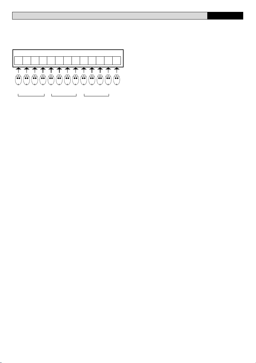
Locazioni di memoria della ricevente RTD
L’assegnazione delle locazioni di memoria della ricevente, al fine di
mantenere una certa uniformità con le numerazioni dei trasmettitori,
avviene secondo queste regole:
1) Se la memoria è vuota il primo trasmettitore (ad es. 01) si inserisce
nella locazione 01 e gli altri a seguire come indicato:
RTD
01 02 03 04 05 06 -- -- -- -- -- -- 100
01 02 03 04 05 06 -- -- -- -- -- -- 00
2) Se alcune locazioni sono occupate da altre trasmittenti, il primo
trasmettitore (ad es. 01) si inserisce nella prima locazione “N01” (101201-301, ecc) disponibile e con un numero di locazioni successive
libere sufficienti all’inserimento:
RTD
01 02 03 04 05 -- --
101
102 103 -- -- 200
01 02 03 -- -- 00
3) Se la ricevente è vuota ed il primo trasmettitore ha un numero
diverso da 01 (es. 35) il primo trasmettitore si inserisce nella locazione
35, gli altri a seguire:
RTD
01 02 03
4) Se alcune locazioni sono occupate e il primo trasmettitore ha un
numero diverso da 01 (es. 35) si inserisce nella prima locazione “N35”
(135-235-335 ecc), disponibile e con un numero di locazioni libere
successive sufficienti all’inserimento:
-- -- --
35 36 37 38
35 36 37 38
-- -- 100
-- -- 00
RTD
-- 35 36 37 38 39 -- 135 136 137 -- -- 200
36 37 -- -- 0035
D811347_03
8
- RTD- Ver. 03
Page 9

MANUALE PER L’INSTALLAZIONE
ITALIANO
5) Nel caso sia richiesta la memorizzazione di un numero maggiore di
100 trasmettitori, è necessario inserire ogni singola confezione trami-
D811347_03
te menu blocchi. Ogni confezione è contraddistinta da uno specifico
numero di serie (S/N):
RTD
01 -- -- 100 101 -- 200-- 201 -- -- 300 --
01 -- -- 00 01 -- -- 00 01 -- -- 00 --
S/N 123.4 S/N 123.4 S/N 123.4
NOTE IMPORTANTI:
• E’ possibile frazionare la confezione in più gruppi (ad es. i
trasmettitori da 01 a 50 in un impianto, da 51 a 65 in un altro, ecc.)
In ogni caso eventuali trasmettitori rimanenti possono essere
utilizzati:
- sulla stessa ricevente RTD in un secondo momento, in altri
blocchi o in modalità manuale/automatica
- in altri impianti RTD, come blocchi o in modalità manuale/
automatica
- in altre trasmittenti in modalità standard.
• Ogni trasmettitore fornito nella confezione è etichettato in modo
univoco secondo questo schema:123.4.01.
Le prime 4 cifre (123.4) identificano il numero di serie della
confezione ed è identico per tutti i trasmettitori appartenenti alla
stessa confezione.
Le ultime due cifre (01 - 02 --> 00) numerano progressivamente
i trasmettitori della confezione.
Viene fornito nella confezione un prestampato nel quale annotare
la destinazione di ogni trasmettitore, se ne consiglia la compila-
zione in modo da facilitare future manutenzioni, aggiornamenti,
sostituzioni ecc.
• Nel caso nella ricevente RTD non sia stato inserito in precedenza
nessun trasmettitore, il primo trasmettitore del primo blocco
memorizzato assume la funzionalità di trasmettitore master. Con-
trassegnarlo con l’apposito adesivo “chiave”.
Messaggi di errore
Se durante l’inserimento dei blocchi si verificano degli errori verificare:
- che le trasmittenti appartengano ad una confezione di blocchi
(ERR1).
- che non si sia invertito l’ordine di inserimento, il primo trasmetti-
tore deve avere un numero indicativo inferiore all’ultimo. Verifica-
re inoltre che il primo e l’ultimo trasmettitore appartangano allo
stesso blocco (ERR2).
- che la ricevente abbia un numero di locazioni libere contigue
sufficiente all’inserimento del blocco di trasmettitori (errore ERR3).
- che il tasto assegnato al canale (T1-T2-T3-T4) sia lo stesso sia nel
primo che nell’ultimo trasmettitore inserito.
6) CLONAZIONE DEI RADIOTRASMETTITORI
Clonazione con rolling code/Clonazione a codice fisso
Fate rifermento alle istruzioni UNIRADIO e alla Guida programmazione CLONIX
7) PROGRAMMAZIONE AVANZATA: COMUNITÀ DI RICEVITORI
Fate rifermento alle istruzioni UNIRADIO e alla Guida programmazione CLONIX
8) MANUTENZIONE
La manutenzione dell’impianto va fatta eseguire regolarmente da
parte di personale qualificato. Le trasmittenti MITTO sono alimen-
tate da 2 batterie al litio da 3V (tipo CR2016). Le trasmittenti TRC sono
alimentate da una batteria alcalina da 12V. Durante la sostituzione
delle batterie tipo CR2016 evitare il contatto dei poli con le mani.
Una diminuzione della portata della trasmittente può essere dovuta
alle batterie che si stanno scaricando. Quando il led della trasmittente
lampeggia, indica che le batterie sono scariche e devono essere
sostituite.
9) DEMOLIZIONE
ATTENZIONE: Avvalersi esclusivamente di personale qualificato.
L’eliminazione dei materiali va fatta rispettando le norme vigenti. Nel
caso di demolizione del sistema, non esistono particolari pericoli o
rischi derivanti dai componenti stessi. È opportuno, in caso di recupero
dei materiali, che vengano separati per tipologia (parti elettriche rame - alluminio - plastica - ecc.). Per lo smaltimento della batteria
riferirsi alla normativa vigente.
Le descrizioni e le illustrazioni del presente manuale non sono
impegnative. Lasciando inalterate le caratteristiche essenziali
del prodotto, la Ditta si riserva di apportare in qualunque momento le modifiche che essa ritiene convenienti per migliorare tecnicamente, costruttivamente e commercialmente il prodotto, senza
impegnarsi ad aggiornare la presente pubblicazione.
RTD- Ver. 03 -
9
Page 10

ACCESSO AI MENU
Premere il tasto OK
OK
BFT
RTD1.0
OK
00
Aggiungi
+/-
Versione software
N° radiocomandi
memorizzati
+/-
OK
aut.
Fig. A
LEGENDA
Premere simultaneamente i tasti + e -.
+/-
8888
+
[ 00 ]
Valore preimpostato
Incremento/riduzione parametri o
/ON
/OFF
commutazione ON/OFF
Scorrimento menu
-
+
(+ = precedente - = successivo)
out1 . .4
-
+
-
+
tutte
OK
La pressione simultanea dei tasti + e consente di uscire dal menu in cui si sta
operando e tornare al precedente, se avviene
al livello principale del menu esce dalla
programmazione e spegne il display.
Le modifiche apportate vengono confermate
solo se seguite dalla pressione di OK.
PRG
Messaggio OK! (conferma avvenuta modifica)
Messaggio KO! (errore valore o funzione)
Messaggio "Attesa" (inserire valore o funzione)
D811347_03
FINE
+/-
FINE
+/-
FINE
-
+
cancella
-
+
verifica
-
+
man. pos.
out1 . .4
-
+
tutte
Blocco out1 . .4
-
+
tutte
OK OK
+/-
OK
codice
-
POS. t0001 . . .
+
database conferma
+/-
OK
leggi codice
-
+
scorri lista
OK
tasto nascosto
OK
primo trasm.
Tx
01 t1 . . . 2048 t4
01 t1 . . . 2048 t4
Tx
tasto nascosto
tasto deisd.00010100
OK
OK
P1
P1
tasto nascosto
P1
tasto deisd.
tasto deisd.
Tx
Tx
ultimo trasm.
10
- RTD- Ver. 03
MENU SEGUENTI
FIG. B
Page 11

Fig. B
D811347_03
+/-
FINE
+/-
FINE
MENU
PRECEDENTI
FIG. A
USCITE
-
+
configura RTD
P1
+/-
OK OK
out1
-
+
out 2
-
+
out 3
-
+
out 4
+/-
lingua
-
+
ita
-
fra
-
deu
-
ENG
-
ESP
FIG. B1A
TRC 1-2
mon.
-
+
bis.
-
+
tem.
-
+
antiag.
+
+
+
+
P1
TRC 4
OK
OK
T1 T2
T3
MITTO 2-4
T1
T2
T3
T1
T4
T2
TRC 1-2
T4
TRC 4
T1 T2
FIG. B2A
passvord 0--- -0-- --0- ---0
-
+
tipo ricevente
cod fisso
-
+
OK
rolling code
OK
RTD- Ver. 03 -
11
Page 12

ENGLISH
INSTALLATION MANUAL
Thank you for buying this product, our company is sure that you will be
more than satisfied with the product’s performance. The product is
supplied with a “Warnings” leaflet and an “Instruction booklet”.
These should both be read carefully as they provide important
information about safety, installation, operation and maintenance.
This product complies with the recognised technical standards and
safety regulations. We declare that this product is in conformity with
the following European Directives: 89/336/EEC and 73/23/EEC (and
subsequent amendments).
GENERAL SAFETY
WARNING! An incorrect installation or improper use of the product
can cause damage to persons, animals or things.
• The “Warnings” leaflet and “Instruction booklet” supplied with
this product should be read carefully as they provide important
information about safety, installation, use and maintenance.
• Scrap packing materials (plastic, cardboard, polystyrene etc)
according to the provisions set out by current standards. Keep
nylon or polystyrene bags out of children’s reach.
• Keep the instructions together with the technical brochure for
future reference.
• This product was exclusively designed and manufactured for the
use specified in the present documentation. Any other use not
specified in this documentation could damage the product and be
dangerous.
• The Company declines all responsibility for any consequences
resulting from improper use of the product, or use which is
different from that expected and specified in the present
documentation.
• Do not install the product in explosive atmosphere.
• The construction components of this product must comply with the
following European Directives:It complies with the 89/336/EEC,
1999/5/CEE, European Directive and subsequent amendments.
As for all non-EEC countries, the above-mentioned standards as
well as the current national standards should be respected in
order to achieve a good safety level.
• The Company declines all responsibility for any consequences
resulting from failure to observe Good Technical Practice when
constructing closing structures (door, gates etc.), as well as from
any deformation which might occur during use.
• The installation must comply with the provisions set out by the
following European Directives:It complies with the 89/336/EEC,
1999/5/CEE, European Directive and subsequent amendments.
• Disconnect the electrical power supply before carrying out any
work on the installation. Also disconnect any buffer batteries, if
fitted.
• Fit an omnipolar or magnetothermal switch on the mains power
supply, having a contact opening distance equal to or greater than
3mm.
• Check that a differential switch with a 0.03A threshold is fitted just
before the power supply mains.
• Check that earthing is carried out correctly: connect all metal parts
for closure (doors, gates etc.) and all system components provided
with an earth terminal.
• Fit all the safety devices (photocells, electric edges etc.) which are
needed to protect the area from any danger caused by squashing,
conveying and shearing.
• Position at least one luminous signal indication device (blinker)
where it can be easily seen, and fix a Warning sign to the structure.
• The Company declines all responsibility with respect to the
automation safety and correct operation when other manufacturers’
components are used.
• Only use original parts for any maintenance or repair operation.
• Do not modify the automation components, unless explicitly
authorised by the company.
• Instruct the product user about the control systems provided and
the manual opening operation in case of emergency.
• Do not allow persons or children to remain in the automation
operation area.
• Keep radio control or other control devices out of children’s reach,
in order to avoid unintentional automation activation.
• The user must avoid any attempt to carry out work or repair on the
automation system, and always request the assistance of qualified
12
- RTD- Ver. 03
personnel.
• Anything which is not expressly provided for in the present
instructions, is not allowed.
1) GENERAL OUTLINE
Programmable self-learning radio receiver system, having the following
main features:
• Receiver which can be cloned with 512 or 2048 codes
• Up to 4 outputs (1 standard + 3 modular) with automatic recognition
of the modules entered
• Outputs which can be configured as monostable, bistable, timed,
anti-aggression
• Programming by means of incorporated display
• Operation with fixed and variable codes
• Compatible with EElink protocol for fast installation and
maintenance
• Group function for automatic entry of groups of transmitters
• Protection of receiver by means of password.
The RTD receiver combines the characteristics of utmost safety in
copying variable code (rolling code) coding with the convenience of
carrying out transmitter “cloning” operations thanks to an exclusive
system.
Cloning a transmitter means creating a transmitter which can be
included automatically within the list of the transmitters memorised in
the receiver, either as an addition or as a replacement of a particular
transmitter.
Therefore it will be possible to remotely program a large number of
additional transmitters, or for example, replacement transmitters for
those which have been lost, without making changes directly to the
receiver.
Replacement cloning is used to create a new transmitter which takes
the place of the one previously memorised in the receiver; in this way
the lost transmitter can be removed from the memory and no longer be
usable.
When coding safety is not a decisive factor, the RTD receiver allows
you to carry out fixed code additional cloning, which although
abandoning the variable code, provides a high number of coding
combinations, while maintaining the option of “copying” any receiver
already programmed.
Using clones when there is more than one receiver (as in the case of
communal buildings),
and especially when a distinction is to be made between clones to be
added to or replaced in individual or collective receivers, could turn out
to be rather difficult. The RTD receiver cloning system for communal
buildings makes it particularly easy to solve the problem of clone
storage for up to 250 individual receivers.
Passageway control is managed by an output with a N.O. contact;
when needed, the number of outputs can be increased by means of
appropriate MOP optional modules to obtain a maximum of 4 output
channels, which can be configured independently.
2) TECHNICAL SPECIFICATIONS
2.1) Receiver
Power supply: .................................................. 230V ±10%50Hz (*)
Frequency: ....................................................................... 433.92MHz
Working temperature: .................................................... -20 to +55°C
Coded by means of: ....................................... Rolling-code algorithm
No. combinations: ................................................................ 4 milliard
Antenna impedance: ................................................. 50 Ohm (RG58)
Dimensions: .......................................................................... see fig. 1
Relay contact: ................................................................... 0,5A, 12V=
Degree of protection: ................................................................ IP 20*
Max no. radio transmitters to be memorised:
Receiver version No. radio transmitters
RTD 512 512
RTD 2048 2048
(*) The degree of protection of the container becomes IP55 with the
use of an accessory supplied on request. Only use fittings suitable for
the container dimensions and cable diameter.
D811347_03
Page 13

INSTALLATION MANUAL
ENGLISH
2.2) MITTO Transmitter
Keys: .......................................................................................... yellow
D811347_03
Power supply: ......................... 2 3V lithium batteries (CR2016 type)
Range: ......................................................................... 50–100 metres
Transmitter versions:
MITTO2 – double-channel, MITTO4 – four-channel
2.3) TRC Transmitter
Keys: ............................................................................................... red
Power supply: ......................................................12V alkaline battery
Range: ......................................................................... 50–100 metres
Transmitter versions:
TRC1 – single-channel, TRC2 – double-channel, TRC4 – four-channel
Accessories (optional):
RTD-RS
Additional board for controlling the RTD receiver via modem
MOP (Fig. 2)
Plug-in module provided with an additional output with N.O. contact.
3) INSTALLATION
Having laid out the connection cable route, proceed to fixing the
support (fig. 1) after marking the two holes through the slots available
as templates on the container. Based on the material the support is
made of, directly use the screws supplied or drill the holes using a
4mm-diameter bit to insert the plugs supplied.
Fully tighten the screws, and compensate any centring errors using
the slots on the container.
4) CONNECTION DIAGRAM (Fig. 3)
Various types of installation are possible depending on the number of
outputs available.
Fig. 4 illustrates an example of an installation for an RTD receiver
provided with 4 outputs.
NOTE: For this type of installation, it is indispensable to choose the
place for the antenna with great care.
RTD
JP4
1-2 Power supply input 230 V ±10% 50/60Hz(1L-2N)
JP3
3 Output for COM common contact
4 Output for NO normally open contact. Contact for door opening
control
JP2
5-6 Input for antenna (5 signal – 6 braid)
JP7-JP8-JP9
Plug-in inputs for MOP optional modules
MOP (optional)
JP1
1-2 Output for NO normally open contact. Contact for door opening
control.
ANTENNA INSTALLATION
Use an antenna tuned to 433MHz.
For antenna to receiver connection, use RG8 coaxial cable.
The presence of metallic masses next to the antenna can interfere
with radio reception. In the case of insufficient transmitter range,
move the antenna to a more suitable position.
5) PROGRAMMING
Transmitters can be memorised by means of the incorporated display
programmer or the UNIRADIO programmer, which makes it possible
to create installations in the “collective receivers” mode, as well as
manage the complete installation database through the EEdbase
software.
In the case of standard installations where no advanced functions are
required, it is possible to proceed to manual transmitter storage,
making reference to programming tables A and B.
Programming menu description
Add:
Allows you to add a transmitter to a receiver memory.
Three modes can be used:
Auto: the transmitter is entered in the first memory location
available.
Manual: the number of the memory location where to enter
the transmitter is requested. This mode turns out to be useful
in the case where you wish to assign progressive numbers to
the various transmitters, in order to simplify any subsequent
elimination from the receiver memory.
Group: menu for automatic entry of groups of transmitters.
See paragraph 5.1 “Transmitter groups”.
After selecting the automatic mode, proceed as follows:
1) Use the + and – buttons to select the output you wish to activate.
If the “all outputs” option is selected, each transmitter key is
automatically associated with its corresponding output (T1– Output
1, T2 – Output 2 etc.).
2) Press hidden key P1 on the transmitter.
3) Press the required transmitter key (T1, T2, T3 or T4) you wish to
associate with the previously selected output.
Note: Hidden key P1 has a different function depending on the
transmitter model.
For TRC 1-2 / MITTO 2-4, press hidden key P1 (fig. B1A).
For TRC 4, the key P1 function corresponds to simultaneously pressing
the 4 transmitter keys or, after opening the battery compartment,
bridging the two P1 points by means of a screwdriver (fig. B1A).
The cloned transmitters are automatically entered in the first memory
location available.
IMPORTANT NOTE: STICK THE KEY LABEL (MASTER) ON THE
FIRST MEMORISED TRANSMITTER.
In the case of manual programming, the first transmitter assigns the
key code to the receiver; this code is necessary in order to carry out
subsequent cloning of the radio transmitters.
Delete:
Allows you to delete one or all the entered transmitters from the
receiver memory.
Code: allows you to eliminate a transmitter from the receiver
memory by entering the memory position number (see Addmanual menu).
List: allows you to eliminate ALL the transmitters from the
receiver memory. You will be requested to confirm this
operation in order to avoid unwanted deletions.
Verify:
Allows you to check the presence of a transmitter in the memory, or
to display the list of all the transmitters entered.
Read code: requires you to press a key on the transmitter
and, if memorised, it displays the memory location number
and the key number.
Scroll list: press the + and - buttons to scroll the list of all the
radio transmitters memorised; keep the button pressed to
speed up list scrolling.
Output:
Allows you to configure the functions of the outputs available in the
receiver.
Configure outputs 1, 2, 3 and 4: select the output you wish
to configure using the + and – buttons.
Each output can be configured according to the following
modes:
1) impulse (monostable). The relay of the associated output
remains picked up as long as the respective transmitter key
remains pressed.
2) step by step (bistable). The relay of the associated output
changes status each time the transmitter key is pressed.
3) timed. Each time the transmitter key is pressed, the output
relay stays picked up for 90 seconds. If the key is pressed
during the count cycle, the count is reset).
RTD- Ver. 03 -
13
Page 14

ENGLISH
INSTALLATION MANUAL
4) anti-panic. The relay of the associated output changes status
if the key is kept pressed for more than 5 seconds. All the keys
of all the transmitters entered in the receiver are automatically
provided with the anti-aggression function, regardless of their
configuration, therefore no key (T1, T2, T3 or T4) needs to be
assigned to the output. Relay commutation lasts 10 sec.
Notes: The default outputs are configured as monostable.
Only one output can be configured with anti-aggression mode.
In the case where it is necessary to check the mode of an output
configuration, select the output and press the OK key. The receiver
displays the previously set function mode as the first option.
If you try to configure an output which is not provided with a MOP
option module, the “module not present” error message will be
displayed.
Configure RTD:
Allows you to set the general system functions.
Language: select one of the languages available (Italian,
French, German, English, Spanish).
Password: use the + and - buttons to enter a password
consisting of 4 digits (from 0 to 9). If a value other than the
default value (0000) is entered, the access password will be
requested for the subsequent configuration attempt. If you do
not wish to protect receiver programming by means of a
password, re-enter default value 0000.
Type of receiver: select the receiver function mode between
fixed code and variable code (rolling-code); the receiver
default configuration is set to rolling-code mode.
5.1) Transmitter groups
Use menu Add --> Group to enter a large number of transmitters
automatically (the maximum limit being the receiver memory capacity).
The company markets packs containing 100 transmitters, appropriately
programmed and numbered from 01 to 100 (transmitter 100 is identified
by figure 00), which can be entered as groups.
Entering a group simply requires the storage of the first and last
transmitters, all the group transmitters included between these will
automatically be stored in the memory.
Standard transmitters cannot be entered in the group menu.
To enter transmitter groups, proceed as follows:
1) Move to menu Add --> Group and select the output to be activated.
Select option “all outputs” to have each transmitter key automatically
associated with the corresponding output (T1- Output1, T2 Output2 etc.).
2) The display shows the message “First transmitter” and then
“hidden key”, press the hidden key (P1 - Fig.5) of the first
transmitter (lowest number) you wish to enter.
3) The display shows the message “key required”: press the Tx key
you wish to associate with the output selected previously.
4) The display shows the message “Last transmitter” and then
“hidden key”, press the hidden key (P1) of the last transmitter
(highest number) you wish to enter.
5) The display shows the message “key required”, press the Tx key
of the last transmitter.
Note: the Tx key selected during this phase must be the same as
that selected in point 3.
6) The display shows the first memory location taken up, confirm by
pressing the “OK” key and the display will show the last memory
location taken up, then press the “OK” key again. In the case
where you wish to cancel a group entered, press the + and – keys
at the same time.
RTD receiver memory locations
In order to maintain some kind of uniformity with the transmitter
numbering, the receiver memory locations are assigned as follows:
1) If the memory is empty, the first transmitter (ex. 01) is entered in
location 01 and the others follow, as indicated:
RTD
01 02 03 04 05 06 -- -- -- -- -- -- 100
01 02 03 04 05 06 -- -- -- -- -- -- 00
2) If some of the locations are taken up by other transmitters, the first
transmitter (ex. 01) is entered in the first “N01” (101-201-301, etc.)
location available, which is followed by a sufficient number of free
entry locations:
RTD
01 02 03 04 05 -- --
101
102 103 -- -- 200
01 02 03 -- -- 00
3) If the receiver is empty and the first transmitter has a number other
than 01 (ex. 35), the first transmitter is entered in location 35, and
the others follow:
RTD
01 02 03
4) If some of the locations are taken up and the first transmitter has
a number other than 01 (ex. 35), it is entered in the first “N35” (135235-335 etc.) location available, which is followed by a sufficient
number of free entry locations:
-- -- --
35 36 37 38
35 36 37 38
-- -- 100
-- -- 00
RTD
-- 35 36 37 38 39 -- 135 136 137 -- -- 200
36 37 -- -- 0035
D811347_03
14
- RTD- Ver. 03
Page 15
INSTALLATION MANUAL
ENGLISH
5) In the case where more than 100 transmitters need to be stored
in the memory, each individual sales pack has to be entered by
D811347_03
means of the group menu. Each pack is identified by a specific
serial number (S/N):
RTD
01 -- -- 100 101 -- 200-- 201 -- -- 300 --
01 -- -- 00 01 -- -- 00 01 -- -- 00 --
S/N 123.4 S/N 123.4 S/N 123.4
IMPORTANT NOTES:
• The sales pack can be divided into several groups (for ex.
transmitters from 01 to 50 in one system, from 51 to 65 in another,
etc.) In any case, any of the remaining transmitters can be used:
- on the same RTD receiver at a later time, in other groups or with
manual/automatic mode,
- in other RTD systems, other groups or with manual/automatic
mode,
- in other transmitters with standard mode.
• Each transmitter contained in the pack is individually labelled
according to the following sequence: 123.4.01.
The first four figures (123.4) identify the pack serial number which
is identical for all the transmitters belonging to the same pack.
The last two figures (01 - 02 --> 00) are used to number the
transmitters in the pack in progressive order.
Each pack includes a printed form where to record the destination
of each transmitter, you are recommended to fill it in to facilitate
future maintenance, updating, replacement etc.
• In the case where no transmitters have been previously entered
in the RTD receiver, the first transmitter in the first group stored
takes on the master transmitter function. Mark it with the appropriate
adhesive “key” label.
Error messages
If any errors occur when entering groups, check that:
- the transmitters belong to one group pack (ERR1);
- the entry order is not reversed, the first transmitter must have an
identification number lower than that of the last one. Also check
that the first and last transmitters belong to the same group
(ERR2);
- the receiver has a sufficient number of consecutive free locations
for entering the transmitter group (ERR3);
- the key assigned to the channel (T1, T2, T3 or T4) is the same for
the first and the last transmitter entered.
6) RADIO-TRANSMITTER CLONING
Rolling-code cloning / Fixed-code cloning
Make reference to the UNIRADIO Instructions and the CLONIX
Programming Guide.
7) ADVANCED PROGRAMMING: COLLECTIVE RECEIVERS
Make reference to the UNIRADIO Instructions and the CLONIX
Programming Guide.
8) MAINTENANCE
The maintenance of the system should only be carried out by
qualified personnel regularly. The MITTO transmitters are supplied
by two 3V lithium battiers (type CR2016).The TRC transmitters are
powered by a 12V alkaline battery.When replacing the batteries type
CR2016 do not touch the poles with thehands.
Any reduction in the transmitter capacity may be due to the batteries
getting flat. When the led of the transmitter flashes, it means that the
batteries are
flat and must be replaced.
9) DISPOSAL
ATTENTION: disposal should only be carried out by qualified
personnel.
Materials must be disposed of in conformity with the current regulations.
In case of disposal, the system components do not entail any particular
risks or danger. In case of recovered materials, these should be sorted
out by type (electrical components, copper, aluminium, plastic etc.).
For battery disposal, refer to the current regulations.
The descriptions and illustrations contained in the present manual
are not binding. The Company reserves the right to make any
alterations deemed appropriate for the technical, manufacturing
and commercial improvement of the product, while leaving its
essential features unchanged, at any time and without undertaking
to update the present publication.
RTD- Ver. 03 -
15
Page 16

ACCESS TO MENUS
Press the OK key
OK
BFT
RTD1.0
OK
00
ADD
+/-
Software version
No. radio control devices
memorised
+/-
OK
aut.
-
Fig. A
LEGENDA
Simultaneously press the + and - keys.
+/-
8888
[ 00 ]
Preset value
Parameter increment/reduction
/ON
/OFF
or ON/OFF commutation
Menu scrolling
-
+
(+ = preceding - = following)
+
OK
Simultaneous pressure of the + and – keys
allows you to exit the active menu and return
to the preceding menu; if this takes place at
the main menu level, programming is exited
and the display switched off.
The modifications made are only confirmed if
the OK key is subsequently pressed.
PRG
Message: Programming in progress
Message: KO! (value or function error)
Message: “Wait” (enter value or function)
D811347_03
out1 . .4
-
+
+
ALL
END
-
delete
+/-
End
-
verify
+/-
End
-
man. pos.
out1 . .4
-
+
OK
hidden button
P1
desired button
Tx
ALL
Group out1 . .4
-
+
+
ALL
OK OK
OK
00010100
First tras.
Tx
desired button
hidden button
P1
P1
hidden button
desired button
Tx
Last tras.
+/-
OK
code
-
database confirm
+
pos. t0001 . . .
+
OK
+/-
OK
read code
-
+
scroll archive
+
01 t1 . . . 2048 t4
01 t1 . . . 2048 t4
OK
16
- RTD- Ver. 03
FOLLOWING
MENUS FIG. B
Page 17

Fig. B
D811347_03
+/-
END
+/-
END
PRECEDING
MENUS FIG. A
output
-
+
configure RTD
P1
+/-
OK OK
out1
-
+
out 2
-
+
out 3
-
+
out 4
+/-
language
-
+
ita
-
fra
-
deu
-
ENG
-
ESP
FIG. B1A
TRC 1-2
+
+
+
+
P1
monos
-
+
bist
-
+
timed
-
+
antipanic
T1 T2
T1
T3
T4
TRC 4
OK
OK
MITTO 2-4
T2
TRC 1-2
TRC 4
T1
T2
T3
T4
T1 T2
FIG. B2A
password 0--- -0-- --0- ---0
-
+
rec. type
codice fisso
-
+
OK
rolling code
OK
RTD- Ver. 03 -
17
Page 18

FRANÇAIS MANUEL D’INSTALLATION
Nous vous remercions pour avoir choisi ce produit. Nous sommes
certains qu’il vous offrira les performances que vous souhaitez. Lisez
attentivement la brochure “Avertissements” et le “Manuel
d’instructions” qui accompagnent ce produit, puisqu’ils fournissent
d’importantes indications concernant la sécurité, l’installation,
l’utilisation et l’entretien. Ce produit est conforme aux règles reconnues
de la technique et aux dispositions de sécurité. Nous certifions sa
conformité avec les directives européennes suivantes: 89/336/CEE,
73/23/CEE (et modifications successives).
SECURITE GENERALE
ATTENTION! Une installation erronée ou une utilisation impropre
du produit peuvent provoquer des lésions aux personnes et aux
animaux ou des dommages aux choses.
• Lisez attentivement la brochure “Avertissements” et le “Manuel
d’instructions” qui accompagnent ce produit, puisqu’ils
fournissent d’importantes indications concernant la sécurité,
l’installation, l’utilisation et l’entretien.
• Eliminer les matériaux d’emballage (plastique, carton, polystyrène
etc.) selon les prescriptions des normes en vigueur. Ne pas
laisser des enveloppes en nylon et polystyrène à la portée des
enfants.
• Conserver les instructions et les annexer à la fiche technique pour
les consulter à tout moment.
• Ce produit a été conçu et réalisé exclusivement pour l’utilisation
indiquée dans cette documentation. Des utilisations non indiquées
dans cette documentation pourraient provoquer des dommages
au produit et représenter une source de danger pour l’utilisateur.
• La Société décline toute responsabilité dérivée d’une utilisation
impropre ou différente de celle à laquelle le produit a été destiné
et qui est indiquée dans cette documentation.
• Ne pas installer le produit dans une atmosphère explosive.
• Les éléments constituant la machine doivent être conformes aux
Directives Européennes suivantes: 89/336/CEE, 1999/5/CEE et
modifications successives. Pour tous les Pays en dehors du
Marché Commun, outre aux normes nationales en vigueur il est
conseillé de respecter également les normes indiquées ci-haut
afin d’assurer un bon niveau de sécurité.
• La Société décline toute responsabilité en cas de non respect des
règles de bonne technique dans la construction des fermetures
(portes, portails etc.), ainsi qu’en cas de déformations pouvant se
produire pendant l’utilisation.
• L’installation doit être conforme aux prescriptions des Directives
Européennes: 89/336/CEE, 1999/5/CEE et modifications
successives.
• Couper l’alimentation électrique avant d’effectuer n’importe quelle intervention sur l’installation. Débrancher aussi les éventuelles
batteries de secours, si présentes.
• Prévoir sur la ligne d’alimentation de la motorisation un interrupteur
ou un magnétothermique omnipolaire avec distance d’ouverture
des contacts égale ou supérieure à 3mm.
• Vérifier qu’en amont de la ligne d’alimentation il y a un interrupteur
différentiel avec seuil de 0,03A.
• Vérifier si l’installation de terre est effectuée correctement:
connecter toutes les parties métalliques de la fermeture (portes,
portails etc.) et tous les composants de la motorisation dotés de
borne de terre.
• Appliquer tous les dispositifs de sécurité (cellules photoélectriques,
barres palpeuses etc.) nécessaires à protéger la zone des dangers
d’écrasement, d’entraînement, de cisaillement.
• Appliquer au moins un dispositif de signalisation lumineuse (feu
clignotant) en position visible, fixer à la structure un panneau de
Attention.
• La Société décline toute responsabilité en matière de sécurité et
de bon fonctionnement de la motorisation si des composants
d’autres producteurs sont utilisés.
• Utiliser exclusivement des pièces originales pour n’importe quel
entretien ou réparation.
• Ne pas effectuer des modifications aux composants de la
motorisation si non expressément autorisées par la Société.
• Informer l’utilisateur de l’installation sur les systèmes de commande
appliqués et sur l’exécution de l’ouverture manuelle en cas
d’urgence.
18
- RTD- Ver. 03
• Ne pas permettre à des personnes et à des enfants de stationner
dans la zone d’action de la motorisation.
• Ne pas laisser des radio commandes ou d’autres dispositifs de
commande à portée des enfants afin d’éviter des actionnements
involontaires de la motorisation.
• L’utilisateur doit éviter toute tentative d’intervention ou de réparation
de la motorisation et ne doit s’adresser qu’à du personnel qualifié.
• Tout ce qui n’est pas expressément prévu dans ces instructions,
est interdit.
1) GENERALITÉS
Système radio récepteur à autoapprentissage, programmable, dont
les caractéristiques principales sont:
• Récepteur clonable à 512 ou 2048 codes.
• Jusqu’à 4 sorties (1 standard + 3 modulaires) avec reconnaissance
automatique des modules insérés.
• Sorties configurables comme monostable, bistable, temporisée,
anti-agression.
• Programmation avec écran incorporé.
• Fonctionnement à code fixe et variable.
• Compatible avec le protocole EElink pour une installation et une
maintenance rapides.
• Fonction bloc pour l’introduction automatique de groupes
d’émetteurs
• Protection du récepteur avec mot de passe.
Le récepteur RTD unit aux caractéristiques de grande sécurité au
copiage du codage à code variable (rolling code), l’avantage de
pouvoir effectuer, grâce à un système exclusif, des opérations de
“clonage” d’émetteurs.
Cloner un émetteur signifie créer un émetteur en mesure de s’insérer
automatiquement dans la liste des émetteurs mémorisés dans le
récepteur en s’ajoutant ou en remplaçant un certain émetteur.
Il sera donc possible de programmer à distance et sans intervenir sur
le récepteur, un grand nombre d’émetteurs en ajout ou en substitution
d’émetteurs qui, par exemple, auraient été perdus.
Le clonage par substitution permet de créer un nouvel émetteur qui
remplace, dans le récepteur, un émetteur précédemment mémorisé.
De cette façon il sera possible d’éliminer un émetteur de la mémoire
et de le rendre inutilisable.
Si la sécurité du codage n’est pas déterminante, le récepteur RTD
permet d’effectuer le clonage en ajout à code fixe qui, en renonçant au
code variable, permet en tous les cas d’avoir un codage avec un grand
nombre de combinaisons, tout en maintenant la possibilité de “copier”
n’importe quel récepteur déjà programmé.
L’emploi de clones s’il y a plus d’un récepteur (comme dans le cas des
communautés), et notamment s’il faut distinguer entre clones à
ajouter ou à remplacer en récepteurs particuliers ou collectifs, pourrait
être très difficile; le système de clonage pour les collectivités du
récepteur RTD est particulièrement simple et résout la mémorisation
des clones jusqu’à 250 récepteurs particuliers.
Le contrôle du passage est géré par une sortie avec contact N.O.; en
cas de besoin, il est possible d’augmenter le nombre de sorties avec
des modules en option spécialement prévus MOP, qui permettent
d’obtenir un maximum de 4 canaux de sortie, configurables de façon
indépendante.
2) CARACTÉRISTIQUES TECHNIQUES
2.1) Récepteur
Alimentation: .................................................. 230V ±10%50Hz (*)
Fréquence: ....................................................................... 433.92MHz
Température de fonctionnement: .................................... -20 / +55°C
Code par: ....................................................... Algorithme rolling-code
N° de combinaisons: ........................................................... 4 milliards
Impédance antenne: .................................................. 50Ohm (RG58)
Dimensions: .......................................................................... voir fig. 1
Contact relais: .................................................................. 0,5A - 12V=
Degré de protection: ................................................................. IP 20*
N° max de radio émetteurs mémorisables
Version récepteur N° radio émetteurs
RTD 512 512
RTD 2048 2048
(*) Le degré de protection de l’enveloppe devient IP55 en utilisant un
D811347_03
Page 19

FRANÇAISMANUEL D’INSTALLATION
accessoire pouvant être fourni en option. N’utiliser que des raccords
indiqués pour les dimensions du récipient et au diamètre du câble.
D811347_03
2.2) Émetteur MITTO
Touches: ....................................................................... Couleur jaune
Alimentation: ........................... 2 Piles Lithium de 3V (type CR2016)
Portée: ........................................................................ 50 / 100 mètres
Versions émetteurs:
MITTO2 – deux canaux, MIITTO4 – quatre canaux
2.3) Émetteur TRC
Touches: ....................................................................... Couleur rouge
Alimentation: ........................................................... Pile Alcaline 12V
Portée: ........................................................................ 50 / 100 mètres
Versions émetteurs:
TRC1-monocanal, TRC2-deux canaux, TRC4-quatre canaux.
Accessoires (en option):
RTD-RS
Carte supplémentaire pour le contrôle par modem du récepteur RTD.
MOP (Fig. 2)
Module encastré doté de sortie supplémentaire contact N.O.
3) INSTALLATION
Après avoir prédisposé le passage des câbles de connexion, fixer le
support (fig. 1), en marquant les deux trous en utilisant les deus œillets
disponibles sur le récipient comme gabarit. Selon le matériel dont le
support est constitué, utiliser directement les vis fournies en dotation
ou bien perforer avec un foret diamètre 4mm pour insérer les chevilles
fournies en dotation.
Serrer à fond les vis en rattrapant d’éventuelles erreurs de centrage
en utilisant les œillets du récipient.
4) SCHÈMA DE CONNEXION (Fig. 3)
Plusieurs types d’installation sont possibles, suivant le nombre de
sorties disponibles.
Un exemple d’installation pouvant être réalisé avec un récepteur RTD
doté de 4 sorties est illustré à la Fig. 4.
NOTE: Dans ce type d’installations, il est indispensable de choisir le
point d’installation de l’antenne avec la plus grande attention.
RTD
JP4
1-2 Entrée alimentation 230 V ±10% 50/60Hz(1L-2N)
JP3
3 Sortie Contact Commun COM
4 Sortie Contact normalement ouvert NO Contact pour pilotage
ouverture porte.
JP2
5-6 Entrée antenne (5 signal - 6 gaine).
JP7-JP8-JP9
Entrées à encastrement pour modules en option MOP
MOP (en option)
JP1
1-2 Sortie Contact normalement ouvert NO. Contact pour pilotage
ouverture porte.
INSTALLATION ANTENNE
Utiliser une antenne accordée sur 433MHz.
Pour la connexion Antenne-Récepteur utiliser un câble coaxial RG58.
La présence de masses métalliques adossées à l’antenne peut
perturber la réception radio. En cas de portée insuffisante de l’émetteur,
déplacer l’antenne à un endroit plus indiqué.
5) PROGRAMMATION
La mémorisation des émetteurs peut se faire au moyen du programmeur
à écran incorporé ou avec le programmeur UNIRADIO qui permet la
réalisation d’installations dans la modalité “communauté de récepteurs”
et la gestion à travers le logiciel EEdbase de la base de données
complète de l’installation.
En cas d’installations standard qui n’exigent pas les fonctions avancées,
il est possible de mémoriser manuellement les émetteurs en se
référant au tableau de programmation A et B.
Description des menus de programmation:
Ajouter:
Permet d’ajouter un émetteur dans la mémoire du récepteur.
Trois modalités sont possibles:
Auto: l’émetteur est inséré dans le premier emplacement de
mémoire libre disponible.
Manuel: le numéro de l’emplacement de mémoire dans
lequel l’émetteur doit être inséré est demandé. Cette modalité
est utile si l’on désire attribuer un numéro progressif aux
différents émetteurs, de façon à faciliter une élimination
successive éventuelle de la mémoire du récepteur.
Bloc: menu d’introduction automatique de groupes
d’émetteurs. Voir paragraphe 5.1 “Blocs d’émetteurs”.
Après avoir sélectionné la modalité automatique ou manuelle, il faut:
1) Sélectionner, avec les touches + et -, la sortie que l’on désire
activer.
En sélectionnant l’option “toutes les sorties”, chaque touche de
l’émetteur est automatiquement accouplée à la sortie
correspondante (T1- Sortie1, T2 - Sortie2 etc.).
2) Appuyer sur la touche cachée P1 de l’émetteur
3) Appuyer sur la touche (T1,T2,T3 ou T4) de l’émetteur que l’on
désire accoupler à la sortie précédemment sélectionnée.
Note: La touche cachée P1 prend un aspect différent suivant le
modèle d’émetteur.
Pour TRC 1-2 / MITTO 2-4, appuyer sur la touche cachée P1 (Fig.
B1A). Pour TRC 4, la touche P1 correspond à l’appui simultané sur les
4 touches de l’émetteur ou, en ouvrant le compartiment de la batterie,
au pontet réalisé avec un tournevis entre les deux plaquettes P1 (Fig.
B1A).
Les émetteurs clonés s’insèrent automatiquement dans le premier
emplacement de mémoire libre.
NOTE IMPORTANTE: MARQUER LE PREMIER ÉMETTEUR
MÉMORISÉ AVEC L’ÉTIQUETTE CLÉ (MAITRE).
Le premier émetteur, en cas de programmation manuelle, attribue le
code clé au récepteur; ce code est nécessaire pour pouvoir effectuer
le clonage suivant des radio émetteurs.
Effacer:
Permet d’effacer de la mémoire du récepteur un ou tous les émetteurs
introduits.
Code: permet d’éliminer un émetteur de la mémoire du
récepteur en introduisant le numéro de position dans la
mémoire (voir menu ajout-manuel).
Archives: permet d’éliminer TOUS les émetteurs de la
mémoire du récepteur. Une confirmation de l’opération est
demandée, afin d’éviter des effacements involontaires.
Vérification:
Permet de vérifier la présence dans la mémoire d’un émetteur ou
d’afficher la liste complète de tous les émetteurs introduire.
Lire codes: il faut appuyer sur une touche de l’émetteur et, si
mémorisé, il affiche le numéro d’emplacement et le numéro
de la touche.
Consulter liste: en utilisant les touches + et -, il est possible
de faire défiler la liste de toutes les radio commandes
mémorisées, l’appui prolongé sur la touche accélère le
défilement de la liste.
Sortie:
Permet de configurer le comportement des sorties présentes dans le
récepteur.
Configuration sortie 1, 2, 3, 4: sélectionner la sortie que l’on
désire configurer, en utilisant les touches + et -.
Chaque sortie peut être configurée selon ces modalités:
1) impulsive (monostable) (le relais de la sortie accouplée
reste attirée tant que la touche correspondante de l’émetteur
reste enfoncée).
2) pas-à-pas (bistable) (le relais de la sortie accouplée
change d’état à chaque appui sur la touche de l’émetteur).
RTD- Ver. 03 -
19
Page 20

FRANÇAIS MANUEL D’INSTALLATION
3) temporisée (à chaque appui sur la touche de l’émetteur,
le relais de la sortie reste attiré pendant 90 secondes. Des
appuis sur la touche pendant le cycle de comptage remettent
à zéro le comptage).
4) anti-agression (le relais de la sortie accouplée change
d’état si l’appui sur la touche de l’émetteur dure plus de 5
secondes). Toutes les touches de tous les émetteurs insérés
dans le récepteur sont automatiquement dotées de la fonction
anti-agression, indépendamment de leur configuration, donc
l’attribution d’une touche (T1, T2, T3 ou T4) à la sortie n’est pas
nécessaire.La commutation du relais a une durée de 10s.
Notes: Les sorties de défaut sont configurées comme monostables.
Une seule sortie peut être configurée en modalité anti-agression.
S’il est nécessaire de vérifier la modalité dans laquelle une sortie a été
configurée, il faut la sélectionner et appuyer sur la touche OK. Le
récepteur affiche comme première option la modalité de fonctionnement
précédemment réglée.
Si l’on cherche à configurer une sortie non dotée de module option
MOP le message d’erreur “module non présent” sera affiché.
Configuration RTD:
Permet de programmer les fonctions générales du système.
Langue: sélectionner la langue voulue parmi celles disponibles
(Italien, français, allemand, anglais, espagnol).
Password: avec les touches +/-, il est possible d’introduire un
mot de passe constitué de 4 chiffres (0 à 9). Si l’on compose une
valeur différente de celle de défaut (0000), le système demandera
le mot de passe d’accès lors de la tentative de configuration
suivante. Si l’on ne désire pas protéger la programmation du
récepteur par un mot de passe, il faut réintroduire la valeur de
défaut 0000.
Type de récepteur: sélectionner la modalité de
fonctionnement du récepteur entre code fixe et code variable
(rolling-code), par défaut le récepteur est configuré en modalité
rolling-code.
5.1) Blocs d’émetteurs
Avec le menu Ajouter --> Bloc il est possible d’introduire
automatiquement un grand nombre d’émetteurs (limite maxi: la capacité
de mémoire du récepteur). La firme commercialise des boîtes de 100
émetteurs spécialement programmés et numérotés de 01 à 100
(l’émetteur 100 est indiqué par le chiffre 00), pour l’introduction en
blocs.
L’introduction d’un bloc exige tout simplement la mémorisation d’un
premier et d’un dernier émetteur: tous les émetteurs du bloc compris
entre ces deux seront automatiquement mémorisés.
Il n’est pas possible d’introduire des émetteurs standard dans le
menu bloc.
Pour l’introduction de blocs d’émetteurs, procéder comme suit:
1) Aller au menu Ajouter --> Bloc et sélectionner la sortie à activer.
En sélectionnant l’option “toutes les sorties” chaque touche de
l’émetteur est automatiquement accouplée à la sortie
correspondante (T1- Sortie1, T2 - Sortie2 etc.).
2) L’écran affiche le message “Premier émetteur”, puis “touche
cachée”, appuyer sur la touche cachée (P1 - Fig. 5) du premier
émetteur (numéro plus bas) que l’on souhaite introduire.
3) L’écran affiche le message “touche souhaitée”: appuyer sur la
touche Tx que l’on souhaite accoupler à la sortie précédemment
sélectionnée.
4) L’écran affiche le message “Dernier émetteur”, puis “touche
cachée”, appuyer sur la touche cachée (P1) du dernier émetteur
(numéro plus haut) que l’on souhaite introduire.
5) L’écran affiche le message “touche souhaitée”; appuyer sur la
touche Tx dans le dernier émetteur.
Remarque: La touche Tx sélectionnée dans cette phase doit être
la même que l’on a sélectionnée au point 3.
6) L’écran affiche le premier emplacement de mémoire occupé,
valider en appuyant sur la touche “OK”, puis l’écran affiche le
dernier emplacement occupé, appuyer sur la touche “OK”. Si l’on
souhaite annuler l’introduction du bloc, appuyer en même temps
sur les touches + et -.
20
- RTD- Ver. 03
Emplacements de mémoire du récepteur RDT
Afin de maintenir une certaine uniformité avec les numérotages des
émetteurs, l’attribution des emplacements de mémoire du récepteur
se fait selon les règles suivantes:
1) Si la mémoire est vide, le premier émetteur (par ex. 01) est placé
dans l’emplacement 01 et les autres de suite, comme indiqué:
RTD
01 02 03 04 05 06 -- -- -- -- -- -- 100
01 02 03 04 05 06 -- -- -- -- -- -- 00
2) Si des emplacements sont occupés par d’autres émetteurs, le
premier émetteur (par ex. 01) est placé dans le premier emplacement
“N01” (101-201-301 etc.) disponible et avec un nombre d’emplacements
libres successifs suffisant à l’introduction:
RTD
01 02 03 04 05 -- --
101
102 103 -- -- 200
01 02 03 -- -- 00
3) Si le récepteur est vide et le premier émetteur a un numéro
différent de 01 (ex. 35) le premier émetteur est placé dans
l’emplacement 35, les autres de suite:
RTD
01 02 03
4) Si des emplacements sont occupés et le premier émetteur a un
numéro différent de 01 (ex. 35), celui-ci est placé dans le premier
emplacement “N35” (135-235-335 etc.) disponible et avec un nombre
d’emplacements libres successifs suffisant à l’introduction:
-- -- --
35 36 37 38
35 36 37 38
-- -- 100
-- -- 00
RTD
-- 35 36 37 38 39 -- 135 136 137 -- -- 200
36 37 -- -- 0035
D811347_03
Page 21

FRANÇAISMANUEL D’INSTALLATION
5) S’il faut mémoriser plus de 100 émetteurs, il faudra introduire
chaque boîte au moyen du menu blocs. Chaque boîte est caractérisée
D811347_03
par un numéro de série spécifique (S/N):
RTD
01 -- -- 100 101 -- 200-- 201 -- -- 300 --
01 -- -- 00 01 -- -- 00 01 -- -- 00 --
S/N 123.4 S/N 123.4 S/N 123.4
REMARQUES IMPORTANTES:
• Il est possible de diviser la boîte en plusieurs groupes (par ex. les
émetteurs de 01 à 50 dans une installation, de 51 à 65 dans une
autre etc.) En tous les cas, les éventuels émetteurs restants
peuvent être utilisés:
- sur le même récepteur RTD par la suite, en d’autres blocs ou en
modalité manuelle/automatique
- en d’autres installations RTD, en tant que blocs ou en modalité
manuelle/automatique
- en d’autres émetteurs en modalité standard.
• Chaque émetteur fourni dans la boîte est étiqueté de façon
univoque selon ce schéma: 123.4.01.
Les 4 premiers chiffres (123.4) identifient le numéro de série de la
boîte et il est le même pour tous les émetteurs appartenant à la
même boîte.
Les deux derniers chiffres (01-02 --> 00) numérotent
progressivement les émetteurs de la boîte.
Dans la boîte est fourni un formulaire dans lequel il faut marquer
la destination de chaque émetteur. Il est conseillé de le remplir
afin de faciliter les opérations d’entretien, les mises à jours, les
remplacements futures etc.
• Si dans le récepteur RTD aucun émetteur n’a été précédemment
introduit, le premier émetteur du premier bloc mémorisé fait
fonction d’émetteur maître. Il faut le marquer avec l’adhésif
spécial “clé”.
Messages d’erreur
Si pendant l’introduction des blocs, des erreurs se produisent, il faut
vérifier:
- que les émetteurs appartiennent à une boîte de blocs (ERR1).
- que l’ordre d’introduction n’a pas été inversé: le premier émetteur
doit avoir un numéro indicatif inférieur au dernier. Vérifier en outre
que le premier et le dernier émetteur appartiennent au même bloc
(ERR2).
- que le récepteur a un nombre d’emplacements libres contigus
suffisant à l’introduction du bloc d’émetteurs (erreur ERR3).
- que la touche attribuée au canal (T1-T2-T3-T4) est le même tant
dans le premier que dans le dernier émetteur introduit.
6) CLONAGE DES RADIOÉMETTEURS
Clonage avec rolling code/Clonage à code fixe
Se référer aux instructions UNIRADIO et au Guide de programmation
CLONIX
7) PROGRAMMATION AVANCÉE: COMMUNAUTÉ DE
RÉCEPTEURS
Se référer aux instructions UNIRADIO et au Guide de programmation
CLONIX
8) ENTRETIEN
L’entretien de l’installation doit être effectué régulièrement de la
part de personnel qualifié. Les émetteurs sont alimentés par 2
batteries au lithium de 3V (type CR2016). Les émetteurs TRC sont
alimentés par une pile alcaline 12V.Pendant le remplacement des
batteries de type CR2016, il faut éviter le contact des pôles avec les
mains.
Une réduction de la portée de l’émetteur peut être due aux batteries
en train de se décharger. Quand la led de l’émetteur clignote, cela
indique que les batteries sont à plat et qu’il faut les remplacer.
9) DÉMOLITION
ATTENTION: s’adresser uniquement à du personnel qualifié.
L’élimination des matériaux doit être faite en respectant les normes en
vigueur. En cas de démolition du système, il n’existe aucun danger ou
risque particulier dérivant de ses composants. En cas de récupération
des matériaux, il sera opportun de les trier selon leur genre (parties
électriques - cuivre - aluminium - plastique - etc.). Pour l’élimination de
la batterie, se référer aux normes en vigueur.
Les descriptions et les figures de ce manuel n’engagent pas le
constructeur. En laissant inaltérées les caractéristiques
essentielles du produit, la Société se réserve le droit d’apporter
à n’importe quel moment les modifications qu’elle juge opportunes
pour améliorer le produit du point de vue technique, commercial
et de construction, sans s’engager à mettre à jour cette publication.
RTD- Ver. 03 -
21
Page 22

ACCES AUX MENUS
Appuyer sur la
touche OK
OK
BFT
RTD1.0
OK
00
adjouter
+/-
Version logiciel
N° commandes radio
mémorisées
+/-
OK
aut.
Fig. A
LEGENDA
Appuyer simultanément sur les touches + et -.
+/-
8888
+
[ 00 ]
Valeur prédéfinie
Incrément/réduction paramètres ou
/ON
/OFF
commutation ON/OFF
Défilement du menu
-
+
(+ = précédent - = suivant)
out1 . .4
-
+
-
+
tous
OK
L’appui simultané sur les touches + et –
permet de sortir du menu et de retourner au
menu précédent; si cela a lieu au niveau
principal du menu, on sort de la
programmation et l’écran s’éteint.
Les modifications effectuées ne sont validées
que si elles sont suivies par l’appui de OK.
Message Programmation en cours
PRG
Message KO! (erreur de la valeur ou de la
fonction)
Message "Attendez s.v.p." (introduire la valeur
ou la fonction)
D811347_03
FIN
+/-
FIN
+/-
FIN
-
+
effacer
-
+
verifcation
-
+
man. pos.
out1 . .4
-
+
tous
Bloc
out1 . .4
-
+
tous
OK OK
+/-
OK
codes
-
pos. t0001 . . .
+
archives confirmer
+/-
OK
lire codes
-
+
consulter liste
OK
touche cachee
OK
Premier Em.
00010100
Tx
touche desiree
OK
touche cachee
P1
P1
P1
touche cachee
touche desiree
touche desiree
Dernier Em.
Tx
Tx
01 t1 . . . 2048 t4
01 t1 . . . 2048 t4
OK
22
- RTD- Ver. 03
MENUS SUIVANTS
FIG. B
Page 23

Fig. B
D811347_03
+/-
FIN
+/-
FIN
MENUS
PRECEDENTS
FIG. A
sortie
-
+
configuratiom RTD
P1
+/-
OK OK
sortie1
-
+
sortie 2
-
+
sortie 3
-
+
sortie 4
+/-
langue
-
+
FIG. B1A
TRC 1-2
monos.
-
bista.
-
tempo.
-
antiag.
ita
-
+
fra
-
+
deu
-
+
ENG
-
+
ESP
P1
TRC 4
OK
+
+
+
OK
T1 T2
T3
MITTO 2-4
T1
T2
T3
T1
T4
T2
TRC 1-2
T4
TRC 4
T1 T2
FIG. B2A
passvord 0--- -0-- --0- ---0
-
+
type recepteur
code fixe
-
+
OK
rolling code
OK
RTD- Ver. 03 -
23
Page 24

DEUTSCH
MONTAGEANLEITUNG
Wir danken Ihnen, daß Sie sich für diese Anlage entschieden haben.
Ganz sicher wird sie mit ihren Leistungen Ihren Ansprüchen vollauf
gerecht werden. Lesen Sie aufmerksam die Broschüre “Hinweisen“
und die “Gebrauchsanweisung“ durch, die dem Produkt beiliegen.
Sie enthalten wichtige Hinweise zur Sicherheit, Installation, Bedienung
und Wartung der Anlage. Dieses Produkt genügt den anerkannten
technischen Regeln und Sicherheitsbestimmungen. Wir bestätigen,
daß es mit folgenden Europäischen Richtlinien übereinstimmt: 89/
336/EWG, 73/23/EWG (und ihren nachfolgende Änderungen).
ALLGEMEINE SICHERHEITSHINWEISE
ACHTUNG! Die falsche Installation oder der unsachgemäße
Gebrauch der Anlage kann Personen-oder Sachschäden nach
sich ziehen.
• Lesen Sie aufmerksam die Broschüre mit den “Hinweisen” und
die “Gebrauchsanweisung”, die dem Produkt beiliegen. Sie
enthalten wichtige Hinweise zur Sicherheit, Montage, Bedienung
und Wartung der Anlage.
• Verpackungsmaterialien (Plastik, Karton, Polystyrol u. a.) sind
nach den einschlägigen Vorschriften zu entsorgen. Keine Plastikoder Polystyroltüten in Reichweite von Kindern liegenlassen.
• Die Anleitung ist für zukünftige Einsichtnahme als Beilage zur
technischen Akte aufzubewahren.
• Dieses Produkt wurde ausschließlich für den Gebrauch entwickelt
und gebaut, wie er in dieser Dokumentation beschrieben wird.
Davon abweichende Verwendungen können Schadens und
Gefahrenquellen darstellen.
• Der Hersteller lehnt jede Verantwortung für Folgen ab, die durch
den unsachgemäßen oder nicht bestimmungsgemäßen, weil in
dieser Dokumentation nicht genannten Gebrauch entstehen.
• Die Anlage darf nicht in explosionsgefährdeter Atmosphäre
installiert werden.
• Die Bauteile der Maschine müssen den folgenden Europäischen
Richtlinie 89/336/EWG , 1999/5/EWG, und nachfolgenden
Änderungen. Für alle Länder außerhalb der EWG gilt: Außer den
geltenden Landesvorschriften sollten aus Sicherheitsgründen
auch die oben genannten Bestimmungen beachtet werden.
• Der Hersteller lehnt jede Verantwortung für Folgen ab, die durch
nicht fachgerechte Ausführung von Schließvorrichtungen (Türen,
Tore usw.), oder durch Verformungen während des Betriebes
entstehen.
• Die Montage muß im Einklang mit folgenden Europäischen
Richtlinie 89/336/EWG , 1999/5/EWG, und nachfolgenden
Änderungen.
• Vor jedem Eingriff an der Anlage die Stromversorgung
unterbrechen. Auch vorhandene Pufferbatterien sind
abzuklemmen.
• Versehen Sie die Versorgungsleitung der Anlage mit einem
Schalter oder allpoligen magnetthermischen Schutzschalter mit
einem Kontaktabstand von mindestens 3mm.
• Der Versorgungsleitung muß ein Fehlerstromschutzschalter mit
einer Schwelle von 0.03A vorgeschaltet sein.
• Prüfen Sie. ob der Erdungsanschluß richtig vorgenommen wurde:
Alle Metallteile der Schließanlage (Türen, Tore etc.) und alle
Anlagenkomponenten müssen mit einer Erdungsklemme
verbunden sein.
• Bringen Sie alle Sicherheitsvorrichtungen an (Fotozellen,
Sicherheitsleisten etc.), die im Bereich zum Schutz vor Quetschungen,
Mitschleifen und Schnittverletzungen erforderlich sind.
• Bringen Sie in gut sichtbarer Position mindestens eine
Leuchtsignaleinrichtung (Blinklampe) an und befestigen Sie am
Torgestell ein Warnschild.
• Der Hersteller lehnt jede Verantwortung für die Sicherheit und die
Funktionstüchtigkeit der Anlage ab, wenn Komponenten anderer
Produzenten verwendet werden.
• Für Wartungen und Reparaturen ausschließlich Originalteile
verwenden.
• Keine Umbauten an Anlagenkomponenten vornehmen, wenn sie
nicht ausdrücklich vom Hersteller genehmigt wurden.
• Weisen Sie den Anlagenbetreiber in die vorhandenen
Steuerungssysteme und die manuelle Toröffnung im Notfall ein.
• Kindern oder Erwachsenen darf nicht gestattet werden, im
Aktionsbereich der Anlage zu verweilen.
• Keine Fernbedienungen oder andere Steuerungsvorrichtungen in
Reichweite von Kindern liegenlassen. Sie könnten die Anlage
24
- RTD- Ver. 03
versehentlich in Gang setzen.
• Der Betreiber hat jeden Versuch eines Eingriffes oder der Reparatur
zu unterlassen. Nur entsprechend qualifizierte Fachleute sind
hierzu befugt.
• Alles, was nicht ausdrücklich in dieser Anleitung genannt ist, ist
untersagt.
1) ÜBERSICHT
Funkempfangsanlage mit Selbstlerntechnik, programmierbar, mit
folgenden Merkmalen:
• Klonierbarer Empfänger mit 512 oder 2048 Codes
• Bis zu 4 ausgänge (1 standard + 3 modular) mit automatischen
Erkennung der einbezogenen Module.
• Ausgänge konfigurierbar als monostabil, bistabil, zeitgeschaltet,
Aggressionssicherung.
• Programmierung am eingebauten Display.
• Betrieb mit festem und variablem Code.
• Kompatibel mit dem Protokoll EElink für eine schnelle Installation
und Wartung.
• Funktion für das automatische blockweise Einfügen von
Sendergruppen
• Paßwortschutz des Empfängers.
Der Empfänger RTD vereinigt die extrem sichere Übertragung variabel
codierter Verschlüsselungen (Rollcode) mit dem praktischen und
exklusiven System zum "Klonieren" von Sendern.
Als Klonieren eines Senders bezeichnet man die Erzeugung eines
Senders, der in der Lage ist, sich automatisch in die Liste der im
Empfänger gespeicherten Sender einzufügen, und zwar zusätzlich zu
den bereits bestehenden oder als Ersatz für einen bestimmten Sender.
Es läßt sich somit auf Distanz und ohne Eingriff in den Empfänger eine
Vielzahl von Sendern programmieren, die hinzugefügt werden oder an die
Stelle anderer Sender treten, die beispielsweise verloren gegangen sind.
Beim ersetzenden Klonieren wird ein neuer Sender erzeugt, der im
Empfänger die Stelle eines bereits gespeicherten Senders einnimmt.
Dieser wird auf diese Weise aus dem Speicher entfernt und unbenutzbar
gemacht.
Wenn die Verschlüsselungssicherheit keine entscheidende Rolle spielt,
gestattet der Empfänger RTD die hinzufügende Klonierung mit
Festcode, der - obwohl er auf die Vorteile des variablen Codes
verzichtet - immer noch eine Verschlüsselung mit einer großen Zahl
von Kombinationsmöglichkeiten ermöglicht. Die Möglichkeit zum
"Kopieren" jedes beliebigen bereits programmierten Empfängers
besteht auch in diesem Fall.
Die Verwendung von Klonen bei einem Bestand von mehr als einem
Empfänger (wie im Fall von Gemeinschaftsanlagen) könnte sich
relativ schwierig gestalten, besonders wenn zwischen Klonen
unterschieden wird, die in einzelne oder gemeinschaftliche Empfänger
zusätzlich oder ersetzend eingefügt werden. Das Klonierungssystem
für Gemeinschaftsanlagen mit dem Empfänger RTD ist besonders
einfach zu handhaben und gestattet die Speicherung der Klone von
bis zu 250 Einzelempfängern.
Die Durchgangskontrolle wird von einem Ausgang mit Schließkontakt
gesteuert. Im Bedarfsfall sind durch Zusatzmodule MOP insgesamt
bis zu 4 unabhängig voneinander konfigurierbare Ausgangskanäle
erhältlich.
2) TECHNISCHE DATEN
2.1) Empfänger
Versorgungsspannung: ................................... 230V ±10%50Hz (*)
Frequenz: ......................................................................... 433.92MHz
Betriebstemperatur: ......................................................... -20 / +55°C
Verschlüsselung mittels: .................................. Rollcode-Algorithmus
Kombinationen: ................................................................ 4 Milliarden
Antennenimpedanz: ................................................... 50Ohm (RG58)
Abmessungen: ................................................................. siehe Fig. 1
Relaiskontakt: ................................................................... 0,5A - 12V=
Schutzgrad: ............................................................................... IP 20*
Max. speicherbare Fundsender:
Empfängerversion Anzahl Funksender
RTD 512 512
RTD 2048 2048
(*) Der Schutzgrad der Umhüllung erhöht sich auf IP55, wenn man ein
auf Anfrage erhältliches Zubehörteil benutzt. Benutzen Sie nur
D811347_03
Page 25

MONTAGEANLEITUNG
DEUTSCH
Verbindungsstücke, die zu den Abmessungen des Behälters und zum
Kabeldurchmesser passen.
D811347_03
2.2) Sender MITTO
Tasten: .......................................................................................... Gelb
Versorgungsspannung: .............. 2 Litiumbatterien 3V (Typ CR2016)
Reichweite : 50 - 100 Meter
Senderversionen:
MITTO2 - Zweikanal, MITTO4 - Vierkanal.
2.3) Sender TRC
Tasten: ............................................................................................ Rot
Versorgungsspannung: .......................................... Alkalibatterie 12V
Reichweite: .................................................................. 50 - 100 Meter
Senderversionen:
TRC1-Einkanal, TRC2-Zweikanal, TRC4-Vierkanal.
Zubehör (Extras):
RTD-RS
Zusatzkarte für die Steuerung des Empfängers RTD per Modem.
MOP (Fig. 2)
Einsteckmodul mit zusätzlichem Schließkontaktausgang.
3) INSTALLATION
Nach der Verlegung der Anschlußkabel wird die Halterung befestigt
(Fig.1): Die beiden Bohrungen werden vorher angezeichnet, die
beiden Langlöcher im Behälter als Schablone benutzend. Je nach
Material, aus dem der Untergrund besteht, werden entweder direkt die
mitgelieferten Schrauben benutzt oder alternativ mit einem 4 mm
durchmessenden Bohrer ein Loch gebohrt, in das die beiliegenden
Dübel eingeführt werden.
Die Schrauben werden vollständig angezogen, Zentrierfehler sind mit
Hilfe der Langlöcher im Behälter ausgleichbar.
4) ANSCHLUSSPLAN (Fig. 3)
Je nach Anzahl der verfügbaren Ausgänge sind mehrere Arten der
Installation möglich.
Als Beispiel für eine mögliche Anlage mit einem Empfänger RTD und
4 Ausgängen ist in Fig. 4 dargestellt.
ANMERKUNG: Bei diesem Anlagentyp ist es von wesentlicher
Bedeutung, daß der Standort der Antenne mit größter Sorgfalt
ausgewählt wird.
RTD
JP4
1-2 Eingang Netz 230 V ±10% 50/60Hz(1L-2N)
JP3
3 Ausgang Common Kontakt COM
4 Ausgang Schließer NO. Steuerkontakt für Türöffnung.
JP2
5-6 Antenneneingang (5 Signal - 6 Geflecht).
JP7-JP8-JP9
Einsteck-Eingänge für Zusatzmodule MOP
MOP (optional)
JP1
1-2 Ausgang Schließer NO. Steuerkontakt für Türöffnung.
ANTENNENINSTALLATION
Verwenden Sie eine auf die Frequenz von 433MHz abgestimmte
Antenne.
Die Verbindung Antenne-Empfänger wird mit einem Koaxialkabel
RG58 hergestellt.
Metallische Massen in Antennennähe können den Funkempfang
stören. Falls die Reichweite des Senders nicht ausreicht, versetzen
Sie die Antenne an eine Stelle mit besserem Empfang.
5) PROGRAMMIERUNG
Die Sender können mit dem eingebauten Programmierdisplay oder
mit Hilfe des Programmiergerätes UNIRADIO gespeichert werden. Mit
letzterem lassen sich Anlagen im Modus “Gemeinschaftsempfänger”
einrichten, die sich mit dem anlagenintegrierten Datenbankprogramms
EEdbase komplett verwalten läßt.
Bei Standardanlagen, wo die fortgeschrittenen Funktionen nicht
benötigt werden, sind die Sender von Hand speicherbar. Orientieren
Sie sich an den Programmiertabellen A und B.
Beschreibung der Programmiermenüs:
Zufügen:
Gestattet das Hinzufügen eines Senders zum Empfängerspeicher.
Drei Möglichkeiten bestehen:
Auto: Der Sender wird an die erste frei verfügbare Stelle des
Speichers gesetzt.
Manuell: Hier ist anzugeben, an welcher Speicherstelle der
Sender eingefügt werden soll. Diese Art der Programmierung
erweist sich als nützlich, wenn den einzelnen Sendern eine
fortlaufende Nummer zugewiesen werden soll, um die spätere
Löschung eines Senders aus dem Empfängerspeicher zu
erleichtern.
Block: Menü für das automatische Einfügen von
Sendergruppen. Siehe Abschnitt 5.1 “Senderblöcke”.
Nach der Auswahl des automatischen oder manuellen Modus geht es
folgendermaßen weiter:
1) Auswahl des zu aktivierenden Ausganges mit den Knöpfen + und -.
Auswahl der Option “Alle Ausgänge”: Jede Sendertaste wird
automatisch dem entsprechenden Ausgang zugewiesen (T1Ausgang1, T2 - Ausang2 etc.).
2) Betätigung der verborgenen Sendertaste P1
3) Betätigung der Taste (T1, T2, T3 oder T4) desjenigen Senders,
der dem zuvor gewählten Ausgang zugeordnet werden soll.
Anmerkung: Das Aussehen der Taste P1 unterscheidet sich von
Modell zu Modell:
Für TRC 1-2 / MITTO 2-4 drücken Sie den verborgenen Knopf P1 (Fig.
B1A). Bei TRC 4 entspricht die Taste P1 dem gleichzeitigen Drücken
der 4 Sendertasten. Die gleiche Wirkung hat nach Öffnung des
Batteriefachs die Überbrückung der beiden Anschlußstellen P1 mit
einem Schraubendreher (Fig. B1A).
Die klonierten Sender werden automatisch in die erste freie
Speicherstelle eingefügt.
WICHTIGE ANMERKUNG: KENNZEICHNEN SIE DEN ALS ERSTEN
GESPEICHERTEN SENDER MIT DER SCHLÜSSELMARKIERUNG
(MASTER).
Der erste Sender weist bei der manuellen Programmierung dem
Empfänger den Schlüsselcode zu; dieser Code ist erforderlich, um
anschließend die Funksender klonieren zu können.
Lösche:
Gestattet das Entfernen eines oder sämtlicher eingefügter Sender aus
dem Empfängerspeicher.
Codierung: Gestattet es, durch Eingabe der
Speicherstellennummer einen Sender aus dem
Empfängerspeicher zu entfernen (siehe Menü "Hinzufügenmanuell").
Database: Gestattet das Entfernen ALLER Sender aus dem
Empfängerspeicher. Um ein ungewolltes Löschen zu
verhindern, wird zusätzlich die Bestätigung des
Programmierenden eingeholt.
Kontrolle:
Mit dieser Funktion wird geprüft, ob ein Sender im Speicher vorhanden
ist. Es kann auch die vollständige Liste aller eingefügten Sendeeinheiten
angezeigt werden.
Codeirung lesen: Erforderlich ist die Betätigung einer
Sendertaste. Ist der Sender bereits gespeichert, wird die
Speicherstellennummer und die Tastennummer angezeigt.
Listendurchlauf: Mit den Knöpfen + und - läßt sich das
Verzeichnis sämtlicher gespeicherter Fernbedienungen
durchlaufen. Bei fortlaufender Betätigung der Taste wird der
Listendurchlauf beschleunigt.
Ausgang:
Mit dieser Funktion läßt sich das Verhalten der Empfängerausgänge
konfigurieren.
Konfigurieren Ausgang 1,2,3,4: Mit den Knöpfen + und werden die einzustellenden Ausgänge gewählt.
Jeder Ausgang kann auf eine der folgenden Arten konfiguriert
werden:
1) Impuls (monostabil) Das zugehörige Ausgangsrelais
bleibt solange angezogen, wie die entsprechende Sendertaste
RTD- Ver. 03 -
25
Page 26

DEUTSCH
MONTAGEANLEITUNG
gedrückt wird.
2) Schrittschaltung (bistabil) das zugehörige
Ausgangsrelais ändert bei jeder Betätigung der Sendertaste
seinen Zustand
3) Zeitgest bei jeder Betätigung der Sendertaste wird das
Ausgangsrelais für 90 Sekunden angezogen. Das Drücken
der Taste während dieser Dauer läßt die Rückzählphase von
vorne beginnen.
4) Aggressionssicherung (Antigr.) das zugehörige
Ausgangsrelais ändert seinen Zustand, wenn die Sendertaste
länger als 5 Sekunden betätigt wird.
den Empfänger eingefügten Sender sind automatisch unabhängig
von ihrer Konfigurierung mit der Aggressionsschutzfunktion
ausgestattet, die Zuordnung einer Taste (T1, T2, T3 oder T4) zum
Ausgang ist deshalb nicht erforderlich.Die Umschaltdauer des
Relais beträgt 10 Sek.
Anmerkungen: Die Ausgänge sind werkseitig als monostabil
konfiguriert.
Nur ein Ausgang kann im Modus Aggressionssicherung konfiguriert
werden.
Falls erforderlich, kann die Konfiguration eines Ausgangs abgefragt
werden, indem man ihn auswählt und die Taste OK drückt. Der
Empfänger zeigt als erste Option die zuvor eingestellte Betriebsart an.
Wird versucht, einen Ausgang zu konfigurieren, der nicht mit einem
Zusatzmodul MOP ausgestattet ist, erscheint die Fehlermeldung
“Modul nicht vorhanden”.
RTD Einsellen:
Gestattet die Einstellung der allgemeinen Systemfunktionen.
Sprache: Ausgewählt wird aus den vorhandenen Alternativen
die gewünschte Sprache (Italienisch, Französisch, Deutsch,
Englisch, Spanisch).
Password: Mit den Knöpfen + und - läßt sich ein aus 4 Ziffern (0
bis 9) bestehendes Paßwort eingeben. Wird ein Wert eingegeben,
der von der Werkseinstellung (0000) abweicht, so erscheint beim
nächsten Konfigurationsversuch eine Paßwortabfrage. Soll die
Programmierung des Empfängers nicht durch Paßworteingabe
geschützt werden, ist die Vorbesetzung von 0000 erneut
einzugeben.
Empfängertyp: Ausgewählt wird hier die Betriebsart des
Empfängers, also ob er mit Festcode oder variablem Code
(Rollcode) arbeiten soll. Werkseitig ist für den Empfänger der
Rollcodemodus eingestellt.
5.1) Senderblöcke
Mit dem Menü Hinzufügen --> Block läßt sich eine Vielzahl von
Sendeeinrichtungen automatisch einfügen (beschränkt durch die
Speicherkapazität des Empfangsteils). Der Hersteller bietet Packungen
zu je 100 entprechend programmierten und von 01 bis 100
durchnumerierten Sendeeinrichtungen an (der Sender 100 entspricht
der Zahl 00), die sich blockweise einfügen lassen.
Zum Einfügen eines Blockes braucht nur sein erster und letzter
Sender gespeichert werden, alle dazwischen liegenden Sender des
Blockes werden automatisch mitgespeichert.
Standardsender lassen sich nicht in das Blockmenü einfügen.
Senderblöcke werden wie folgt eingefügt:
1) Das Menü Hinzufügen --> Block aufrufen und den
anzusprechenden Ausgang wählen. Aktiviert man die Option “Alle
Ausgänge”, wird jede Sendertaste automatisch dem zugehörigen
Ausgang zugewiesen (T1- Ausgang1, T2 - Ausgang2 etc.).
2) Auf dem Display erscheint die Meldung “Erster Sender” und
anschließend “verborgene Taste”. Drücken Sie die verborgene
Taste (P1 - Abb. 5) des ersten zum Einfügen vorgesehenen
Senders (der mit der niedrigsten Nummer).
3) Auf dem Display steht nun die Meldung “gewünschte Taste”:
Betätigen Sie die Taste Tx, die dem zuvor ausgesuchten Ausgang
zugewiesen werden soll.
4) Nun steht auf dem Display die Meldung “Letzter Sender” und
anschließend “verborgene Taste”. Drücken Sie die verborgene
Taste (P1) des letzten zum Einfügen vorgesehenen Senders (der
mit der höchsten Nummer).
5) Nachdem das Display die Meldung “gewünschte Taste” zeigt,
wird die Taste Tx auf der letzten Sendeeinrichtung gedrückt.
26
- RTD- Ver. 03
Sämtliche Tasten aller in
Anmerkung: Die Taste Tx, die in dieser Phase betätigt wird, muß
mit der übereinstimmen, die unter Punkt 3 gewählt wurde.
6) Das Display zeigt die erste belegte Speicherstelle, die mit “OK”
bestätigt wird, anschließend erscheint die letzte belegte Stelle,
die wiederum mit “OK” bestätigt wird. Soll das Einfügen des
Blockes abgebrochen werden, drücken Sie gleichzeitig die Tasten
+ und -.
Speicherstellen des Empfängers RDT
Die Speicherstellen der Empfangseinrichtung werden nach folgenden
Regeln zugewiesen, um eine gewisse Einheitlichkeit mit der
Sendernumerierung zu bewahren:
1) Wenn der Speicher leer ist, wird der erste Sender (z. B. 01) an die
Stelle 01 gespeichert, die folgenden wie beschrieben:
RTD
01 02 03 04 05 06 -- -- -- -- -- -- 100
01 02 03 04 05 06 -- -- -- -- -- -- 00
2) Wenn einige Speicherstellen von anderen Sendern belegt sind,
wird der erste Sender (z. B. 01) an die erste freie Stelle “N01” (101201-301 usw.) gespeichert, der genügend freie Stellen folgen, um
den Block einfügen zu können:
RTD
01 02 03 04 05 -- --
101
102 103 -- -- 200
01 02 03 -- -- 00
3) Wenn der Empfänger leer ist und der erste Sender eine andere
Nummer als 01 hat (Bsp. 35), wird der erste Sender an die Stelle
35 gespeichert, die restlichen an die darauf folgenden Stellen:
RTD
01 02 03
4) Wenn einige Speicherstellen belegt sind und der erste Sender
eine andere Nummer als 01 hat (Bsp. 35), wird er an die erste freie
Stelle “N35” (135-235-335 usw.) gespeichert, der genügend freie
Stellen folgen, um den Block einfügen zu können:
-- -- --
35 36 37 38
35 36 37 38
-- -- 100
-- -- 00
RTD
-- 35 36 37 38 39 -- 135 136137 -- -- 200
36 37 -- -- 0035
D811347_03
Page 27

MONTAGEANLEITUNG
DEUTSCH
5) Ist es erforderlich, einen Block von mehr als 100
Sendeeinrichtungen einzufügen, muß jeder Packungsinhalt über
D811347_03
das Blockmenü eingefügt werden. Jede Packung hat eine eigene
Seriennummer (S/N):
RTD
01 -- -- 100 101 -- 200-- 201 -- -- 300 --
01 -- -- 00 01 -- -- 00 01 -- -- 00 --
S/N 123.4 S/N 123.4 S/N 123.4
WICHTIGE ANMERKUNGEN:
• Es ist möglich, den Packungsinhalt in mehrere Gruppen aufzuteilen
(z. B. Einfügen der Sender von 01 bis 50 in eine Anlage, der
Nummern 51 bis 65 in eine andere usw.) Auf jeden Fall lassen sich
Sender, die übrig bleiben, folgendermaßen verwenden:
- für denselben Empfänger RTD zu einem späteren Zeitpunkt, als
Bestandteil anderer Blöcke oder im Modus Manuell / Automatik.
- in anderen Anlagen RTD, als Blöcke oder im Modus Manuell /
Automatik
- in anderen Sendeeinheiten im Standardmodus.
• Jeder im Lieferumfang enthaltene Sender wird durch einen
Aufkleber (z. B. 123.4.01) eindeutig nach folgender Systematik
gekennzeichnet:
Die ersten 4 Ziffern (123.4) bezeichnen die Seriennummer der
Verkaufsverpackung und stimmen deshalb für alle Sender aus
derselben Packung überein.
Mit den letzten beiden Ziffern (01 - 02 --> 00) werden die Sender
in einer Verpackung fortlaufend durchnumeriert.
Der Packung liegt ein Vordruck bei, auf dem die Verwendung
jedes einzelnen Senders eingetragen wird. Es ist ratsam, ihn
auszufüllen, um zukünftige Wartungen, Aktualisierungen,
Ersetzungen usw. zu erleichtern.
• Falls früher in den Empfänger RTD noch kein Sender eingefügt
worden war, bekommt der erste Sender des zuerst gespeicherten
Blockes die Funktion als Mastersender zugewiesen. Kennzeichnen
Sie ihn mit dem Aufkleber, der das "Schlüsselsymbol" trägt.
Fehlermeldungen
Treten während des Einfügens der Blöcke Fehler auf, ist zu prüfen:
- ob die Sender aus dem Block einer Packung stammen (ERR1).
- ob möglicherweise die Reihenfolge für das Einfügen der Sender
nicht eingehalten wurde: Die Kennnummer des ersten Senders
muß niedriger sein als die des letzten. Prüfen Sie außerdem, ob
der erste und letzte Sender zum selben Block gehören (ERR2).
- ob der Empfänger genügend freie, aufeinander folgende
Speicherstellen hat, um den Senderblock aufzunehmen (Fehler
ERR3).
- ob die Taste, die dem Kanal (T1-T2-T3-T4) zugewiesene Taste
beim ersten und letzten eingefügten Sender übereinstimmen.
6) KLONIERUNG DER FUNKSENDER
Klonierung mit Rollcode / Klonierung mit Festcode
Siehe hierzu die Betriebsanleitung UNIRADIO und die
Programmieranleitung CLONIX
7) FORTGESCHRITTENE PROGRAMMIERUNG:
EMPFÄNGERKOLLEKTIV
Siehe hierzu die Betriebsanleitung UNIRADIO und die
Programmieranleitung CLONIX
8) WARTUNG
Die Anlagenwartung ist regelmäßig von Fachleuten vorzunehmen.
Die Handsender MITTO werden von 2 Litiumbatterien mit 3 V gespeist
(Typ CR2016).Die Handsender TRC werden von einer 12v Alkaline
Batterie betrieben.Beim Wechseln der Batterien CR2016 vermeiden
Sie es, die Pole mit den Händen zu berühren.
Wenn die Reichweite des Senders abnimmt, kann es sein, daß die
Batterien fast leer sind. Blinkt die LED des Senders, sind die Batterien
leer und müssen erneuert werden.
9) ENTSORGUNG
ACHTUNG: Diese Tätigkeit ist fachkundigen Personen
vorbehalten.
Die Materialien sind unter Beachtung der geltenden Vorschriften zu
entsorgen. Bei der Entsorgung des Systems bestehen keine
besonderen, von den Komponenten ausgehenden Gefahren oder
Risiken.
Es ist sinnvoll, nach Materialarten zu sortieren und die Stoffe einer
getrennten Entsorgung zuzuführen (Elektrische Komponenten - Kupfer
- Aluminium - Plastik - usw.). Bei der Batterieentsorgung sind die
geltenden Vorschriften zu beachten.
Die Beschreibungen und Abbildungen dieser Betriebsanleitung
sind unverbindlich. Der Hersteller behält sich jederzeit das Recht
vor, unter Beibehaltung der wesentlichen Produkteigenschaften
jene Änderungen vorzunehmen, die er hinsichtlich technischer
und baulicher Verbesserungen sowie zur Erhöhung der
Marktchancen als geboten ansieht. Dabei ist er nicht verpflichtet,
auch diese Ausgabe auf den neuesten Stand zu bringen.
RTD- Ver. 03 -
27
Page 28

MENÜZUGRIFF
Taste OK drücken
OK
BFT
RTD1.0
OK
00
+/-
zufugen
Software-Versione
Zahl gespeicherte
Fernsteuerungen
+/-
OK
aut.
Fig. A
LEGENDA
Gleichzeitig die Tasten + und - drücken.
+/-
8888
+
[ 00 ]
Voreinstellungswert
Erhöhung / Verringerung Parameter
/ON
/OFF
oder Umschaltung ON/OFF
Menüdurchlauf
-
+
(+ = vorheriges - = nächstes)
AUS1 . .4
-
+
-
+
alle
OK
Die gleichzeitige Betätigung der Tasten + und gestattet das Verlassen des Menüs, mit dem man
gerade arbeitet, und die Rückkehr zum
voranggehenden Menü. Werden die Tasten auf der
Hauptmenüebene gedrückt, verläßt man den
Programmiermodus und das Display wird
ausgeschaltet.
Die vorgenommenen Änderungen werden erst nach
Drücken von OK gespeichert.
PRG
Meldung Programmierung läuft
Meldung KO! (Fehler Wert oder Funktion)
Meldung "Warten... "
(Wert oder
Funktion eingeben)
D811347_03
ENDE
+/-
ende
+/-
ende
-
+
loesche
-
+
kontrolle
-
+
man. pos.
AUS1 . .4
-
+
alle
Block
AUS1 . .4
-
+
alle
OK OK
+/-
OK
codierung
-
+
POS. t0001 . . .
database bestaetigen
+/-
OK
codeier lesen
-
+
liste durchlauf
OK
verst. taste
OK
Erster Send.
00010100
verst. taste gevue taste
Tx
OK
P1
gevue taste
P1
P1
verst. tastegevue taste
Tx
Tx
Letzter Send.
01 t1 . . . 2048 t4
01 t1 . . . 2048 t4
OK
28
- RTD- Ver. 03
FOLGENDE MENÜS
FIG. B
Page 29

Fig. B
D811347_03
VORANGEHENDE
+/-
ENDE
+/-
ENDE
MENÜS FIG. A
ausgang
-
+
RTD einstellen
P1
+/-
OK OK
aus 1
-
+
aus 2
-
+
aus 3
-
+
aus 4
+/-
sprache
-
+
ita
-
fra
-
deu
-
ENG
-
ESP
TRC 1-2
+
+
+
+
FIG. B1A
P1
imp
-
+
schritt
-
+
zeitgest
-
+
antiag.
T1 T2
T1
T3
T4
TRC 4
OK
OK
MITTO 2-4
T2
TRC 1-2
TRC 4
T1
T2
T3
T4
T1 T2
FIG. B2A
passvord 0--- -0-- --0- ---0
-
+
empf. type
fest code
-
+
OK
rolling code
OK
RTD- Ver. 03 -
29
Page 30

ESPAÑOL
MANUAL DE INSTALACIÓN
Al agradecerle la preferencia que ha manifestado por este producto,
la empresa está segura de que de él obtendrá las prestaciones
necesarias para sus exigencias. Lea atentamente el folleto
“Advertencias” y el “Manual de instrucciones” que acompañan a
este producto, pues proporcionan importantes indicaciones referentes
a la seguridad, la instalación, el uso y el mantenimiento del mismo.
Este producto cumple los requisitos establecidos por las normas
reconocidas de la técnica y las disposiciones relativas a la seguridad.
Confirmamos su conformidad con las siguientes directivas europeas:
89/336/CEE, 73/23/CEE (y modificaciones sucesivas).
SEGURIDAD GENERAL
ATENCION! Una instalación equivocada o un uso impropio del
producto puede crear daños a personas, animales o cosas.
Es preciso:
• Leer atentamente el folleto “Advertencias” y el “Manual de
instrucciones” que acompañan a este producto, pues
proporcionan importantes indicaciones referentes a la seguridad,
la instalación, el uso y el mantenimiento del mismo.
• Eliminar los materiales de embalaje (plástico, cartón, poliestireno,
etc.) según lo previsto por las normas vigentes. No dejar bolsas
de nylon o poliestireno al alcance de los niños.
• Conservar las instrucciones para adjuntarlas al folleto técnico y
para consultas futuras.
• Este producto ha sido proyectado y construido exclusivamente
para la utilización indicada en esta documentación. Usos no
indicados en esta documentación podrían causar daños al producto
y ser fuente de peligro.
• La Empresa declina toda responsabilidad que derive del uso
impropio del producto o de un uso distinto de aquél para el que
está destinado y que aparece indicado en la presente
documentación.
• No instalar el producto en atmósfera explosiva.
• Los elementos constructivos de la máquina deben ser conformes
a las siguientes Directivas Europeas: 89/336/CEE, 1999/5/CEE y
modificaciones sucesivas. Para todos los Países extra CEE,
además de las normas nacionales vigentes, para asegurar un
buen nivel de seguridad, es conveniente respetar también las
normas citadas antes.
• La Empresa declina toda responsabilidad que derive de la
inobservancia de la Buena Técnica en la construcción de los
elementos de cierre (puertas, cancelas, etc.), así como de las
deformaciones que se podrían verificar durante su uso.
• La instalación debe ser conforme a lo previsto por las siguientes
Directivas Europeas: 89/336/CEE, 1999/5/CEE y modificaciones
sucesivas.
• Cortar el suministro de corriente antes de efectuar cualquier
intervención en la instalación. Desconectar también eventuales
baterías tampón, si las hay.
• Prever, en la red de alimentación del automatismo, un interruptor
o un magnetotérmico omnipolar con una distancia de abertura de
los contactos igual o superior a 3mm.
• Verificar que, antes de la red de alimentación, haya un interruptor
diferencial con un umbral de 0,03A.
• Verificar si la toma de tierra ha sido realizada correctamente: conectar
todas las partes metálicas de cierre (puertas, cancelas, etc.) y todos
los componentes de la instalación provistos de borne de tierra.
• Aplicar todos los dispositivos de seguridad (fotocélulas, barras
sensibles, etc.) necesarios para proteger el área del peligro de
aplastamiento, transporte o cizallado.
• Aplicar al menos un dispositivo de señalización luminosa (luz
intermitente) en posición visible y fijar a la estructura un cartel de
Atención.
• La Empresa declina toda responsabilidad, a efectos de la seguridad
y del buen funcionamiento del automatismo, si se emplean
componentes de otros fabricantes.
• Usar exclusivamente partes originales al realizar cualquier
operación de mantenimiento o reparación.
• No modificar ningún componente del automatismo si antes no se
ha sido expresamente autorizado por la Empresa.
• Instruir al usuario del equipo sobre los sistemas de mando
aplicados y la ejecución de la apertura manual en caso de
emergencia.
• No permitir que personas adultas o niños estacionen en el campo
de acción del automatismo.
30
- RTD- Ver. 03
• No dejar radiomandos u otros dispositivos de mando al alcance
de los niños, para evitar el accionamiento involuntario del automatismo.
• El usuario debe: evitar cualquier intento de intervención o
reparación del automatismo y dirigirse únicamente a personal
cualificado.
• Todo lo que no está expresamente previsto en estas instrucciones
no está permitido.
1) DATOS GENERALES
Sistema radiorreceptor con función de autoaprendizaje, programable,
cuyas principales características son:
• Receptor clonable de 512 ó 2048 códigos.
• Hasta 4 salidas (1 standard + 3 modulares) con reconocimiento
automático de los módulos introducidos.
• Salidas configurables como monoestable, biestable, temporizada,
antiagresión.
• Programación mediante display incorporado.
• Funcionamiento con código fijo y variable.
• Compatible con el protocolo EElink, para agilizar la instalación y
el mantenimiento.
• Función Bloque para la introducción automática de grupos de
transmisores.
• Protección del receptor mediante contraseña.
El receptor RTD une a las características de extrema seguridad, a la
copia de la codificación con código variable (rolling code), la comodidad
de poder efectuar, gracias a un exclusivo sistema, operaciones de
“clonación” de transmisores.
Clonar un transmisor significa generar un transmisor capaz de
introducirse automáticamente en la lista de los transmisores
memorizados en el receptor, agregándose o sustituyendo un
determinado transmisor.
Será, por tanto, posible programar, a distancia y sin intervenir en el
receptor, un gran número de transmisores, agregándolos o
sustituyendo transmisores que, por ejemplo, se hayan extraviado.
La clonación por sustitución permite crear un nuevo transmisor que
toma el lugar, en el receptor, de un transmisor anteriormente
memorizado; de este modo, será posible sacar de la memoria del
receptor un transmisor, no pudiéndolo volver a utilizar.
Cuando la seguridad de la codificación no sea determinante, el
receptor RTD permite efectuar la clonación por adición con código fijo
que, renunciando al código variable, permite, en cualquier caso, tener
una codificación con un elevado número de combinaciones,
manteniendo la posibilidad de “copiar” cualquier receptor ya
programado.
La utilización de clones cuando haya más de un receptor (como en el
caso de las colectividades) y, especialmente, cuando se tenga que
distinguir entre clones que agregar o sustituir en receptores particulares
o colectivos, podría resultar bastante difícil; el sistema de clonación
para colectividades del receptor RTD resulta particularmente sencillo
y resuelve la memorización de los clones hasta 250 receptores
particulares.
El control de la abertura de paso se efectúa a través de una salida con
contacto N.O.; si resulta necesario, es posible incrementar el número
de salidas mediante unos módulos opcionales MOP, que permiten
obtener un máximo de 4 canales de salida, configurables de manera
independiente.
2) DATOS TECNICOS
2.1) Receptor
Alimentación: .................................................. 230 V ±10% - 50 Hz
Frecuencia: ...................................................................... 433.92 MHz
Temperatura de funcionamiento: ................................... -20 / +55 °C
Código por medio de: ..................................... Algoritmo rolling-code
N° combinaciones: ........................................................ 4 mil millones
Impedancia antena: .................................................. 50 Ohm (RG58)
Dimensiones: ............................................................... Véase la fig. 1
Contacto relé: ....................................................................1 A - 12 V=
Grado de protección: ............................................................. IP 20 (*)
N° máx. transmisores memorizables:
Versión receptor N° transmisores
RTD 512 512
RTD 2048 2048
(*) El grado de protección de la envoltura se transforma en IP55
D811347_03
Page 31

MANUAL DE INSTALACIÓN
ESPAÑOL
utilizando un accesorio específico, disponible a petición. Hay que
utilizar únicamente racores adecuados a las dimensiones del
D811347_03
contenedor y al diámetro del cable.
2.2) Transmisor MITTO
Teclas: .......................................................................... Color amarillo
Alimentación: .............................2 pilas de litio de 3 V (tipo CR2016)
Alcance: ......................................................................50 / 100 metros
Versiones de transmisores:
MITTO2 - bicanal, MITTO4 - cuadricanal.
2.3) Transmisor TRC
Teclas: ................................................................................. Color rojo
Alimentación: ......................................................Pila alcalina de 12 V
Alcance: ......................................................................50 / 100 metros
Versiones de transmisores:
TRC1-monocanal, TRC2-bicanal, TRC4-cuadricanal.
Accesorios (opcionales):
RTD-RS
Tarjeta adicional para el control por módem del receptor RTD.
MOP (Fig. 2)
Módulo de acoplamiento dotado de salida adicional con contacto N.O.
3) INSTALACION
Una vez predispuesto el paso de los cables de conexión, hay que
proceder a la fijación del soporte (fig. 1); para ello, hay que marcar los
dos agujeros utilizando los dos orificios a disposición en el contenedor
como plantilla. En base al material de composición del soporte, se
utilizarán directamente los tornillos asignados en el equipamiento
base o bien se perforará con una broca de 4 mm de diámetro para
introducir los tornillos de expansión asignados.
Es necesario atornillar completamente los tornillos, compensando
eventuales errores de centrado con la ayuda de los orificios del
contenedor.
4) ESQUEMA DE CONEXION (Fig. 3)
Son posibles varios tipos de instalaciones en función del número de
salidas disponibles.
Un ejemplo de instalación realizable con un receptor RTD dotado de
4 salidas está ilustrado en la Fig. 4.
NOTA: En este tipo de instalaciones, es indispensable escoger con
mucha atención el punto de instalación de la antena.
RTD
JP4
1-2 Entrada alimentación 230 V ±10% - 50/60 Hz (1L-2N).
JP3
3 Salida Contacto Común COM.
4 Salida Contacto normalmente abierto NO. Contacto para el
control de la abertura de paso.
JP2
5-6 Entrada antena (5 señal -6 trenza).
JP7-JP8-JP9
Entradas de acoplamiento para módulos opcionales MOP.
MOP (opcional)
JP1
1-2 Salida Contacto normalmente abierto NO. Contacto para el
control de la abertura de paso.
INSTALACION DE LA ANTENA
Hay que utilizar una antena sintonizada en los 433 MHz.
Para la conexión Antena-Receptor, debe utilizarse cable concéntrico
RG58.
La presencia de cuerpos metálicos a espaldas de la antena puede
perturbar la recepción radio. En caso de escaso alcance del
transmisor, se tendrá que desplazar la antena hasta un punto
más idóneo.
5) PROGRAMACION
La memorización de los transmisores puede realizarse por medio del
programador con display incorporado o mediante el programador
UNIRADIO, que permite la realización de instalaciones en la modalidad
“comunidad de receptores” y la gestión, mediante el software EEdbase,
de la base de datos completa de la instalación.
En el caso de instalaciones standard en las que no se requieran
funciones avanzadas, es posible proceder a la memorización manual
de los transmisores, tomando como referencia las tablas de
programación A y B.
Descripción de los menús de programación:
Anadir:
Permite agregar, en la memoria del receptor, un transmisor.
Son posibles tres modalidades:
Automática: El transmisor se introduce en la primera
ubicación de memoria libre disponible.
Manual: Se solicita el número de la ubicación de memoria en
la que se quiere introducir el transmisor. Esta modalidad
resulta útil en caso de que se desee atribuir un número
progresivo a los distintos transmisores, a fin de simplificar
una eventual sucesiva eliminación de alguno de ellos de la
memoria del receptor.
Bloque: Menú para la introducción automática de grupos de
transmisores. Véase el apartado 5.1 “Bloques de
transmisores”.
Después de seleccionar la modalidad automática o manual, es
necesario:
1) Seleccionar, con las teclas + y -, la salida que se desea activar.
Seleccionando la opción “todas las salidas”, cada tecla del
transmisor se asocia automáticamente a la salida correspondiente
(T1 - Salida 1, T2 - Salida 2, etc.).
2) Presionar la tecla escondida P1 del transmisor.
3) Presionar la tecla (T1,T2,T3 o T4) del transmisor que se desea
asociar a la salida anteriormente seleccionada.
Nota: La tecla escondida P1 asume un aspecto diferente según el
modelo de transmisor.
Para TRC 1-2 / MITTO 2-4, hay que presionar la tecla escondida P1
(Fig. B 1A). Para TRC 4, presionar la tecla P1 corresponde a presionar
simultáneamente las 4 teclas del transmisor o, abriendo el compartimento de la batería, a puentear con un destornillador los dos contactos
P1 (Fig. B1A).
Los transmisores clonados se introducen automáticamente en la
primera ubicación de memoria libre.
NOTA IMPORTANTE: EL PRIMER TRANSMISOR MEMORIZADO
DEBE MARCARSE CON EL ADHESIVO DE LA LLAVE (MASTER).
El primer transmisor, en el caso de programación manual, asigna el
código clave al receptor; este código resulta necesario para poder
efectuar la sucesiva clonación de los transmisores.
Borra:
Permite cancelar, de la memoria del receptor, uno o todos los
transmisores introducidos.
Código: Permite eliminar un transmisor de la memoria del
receptor introduciendo el número de la posición que el
transmisor ocupa en la memoria de éste último (véase el
menú “Agregar-Manual”).
Base de datos: Permite eliminar TODOS los transmisores de
la memoria del receptor. Se solicita la confirmación de la
operación para evitar cancelaciones involuntarias.
Verificacion:
Permite controlar la presencia, en la memoria de un receptor, de un
transmisor o visualizar la lista completa de todos los transmisores
introducidos.
Leer código: Solicita la presión de una tecla del transmisor
y, si éste resulta memorizado, visualiza el número de ubicación
y el número de la tecla.
Consultar lista: Utilizando las teclas + y -, resulta posible
correr la lista de todos los radiomandos memorizados; la
presión prolongada de la tecla acelera el corrimiento de la
lista.
Salidas:
Permite configurar el comportamiento de las salidas presentes en el
receptor.
Configurar salida 1,2,3,4: Hay que seleccionar la salida que
se desea configurar utilizando las teclas + y -.
Cada salida puede configurarse según las siguientes
modalidades:
RTD- Ver. 03 -
31
Page 32

ESPAÑOL
MANUAL DE INSTALACIÓN
1) Impulsiva (monoestable). El relé de la salida asociada
permanece excitado mientras la correspondiente tecla del
transmisor permanezca presionada.
2) Paso-paso (biestable). El relé de la salida asociada
cambia de estado cada vez que se presiona la tecla del
transmisor.
3) Temporizada. Cada vez que se presiona la tecla del
transmisor, el relé de la salida permanece excitado durante
90 segundos. Si la tecla se presiona durante el ciclo de
cálculo, éste se inicializa de nuevo.
4) Antiagresión. El relé de la salida asociada cambia de
estado si la presión de la tecla del transmisor tiene una
duración superior a 5 segundos.Todas las teclas de todos los
transmisores introducidos en el receptor están dotadas,
automáticamente, de la función antiagresión
independientemente de su configuración; por tanto, la
asignación de una tecla (T1,T2,T3 oT4) a la salida no es
necesaria.
La conmutación del relé tiene una duración de 10 s.
Notas:Las salidas predefinidas están configuradas como
monoestables.
Únicamente una salida puede configurarse en modalidad antiagresión.
En caso de que sea necesario verificar en qué modalidad se ha
configurado una salida, hay que seleccionar ésta y presionar la tecla
OK. El receptor visualiza como primera opción la modalidad de
funcionamiento anteriormente configurada.
Si se trata de configurar una salida no dotada de módulo opcional
MOP, se visualizará el mensaje de error “módulo no presente”.
Configur RTD:
Permite configurar las funciones generales del sistema.
Lengua: Hay que seleccionar el idioma deseado de entre los
puestos a disposición (italiano, francés, alemán, inglés,
español).
Nueva Contraseña (Password): Utilizando las teclas + y -,
resulta posible introducir una contraseña constituida por 4 cifras
(de 0 a 9). Si se introduce un valor diferente al predefinido
(0000), se solicitará la contraseña de acceso al momento de
realizar, sucesivamente, un nuevo intento de configuración. Si
no se desea proteger la programación del receptor mediante
contraseña, hay que volver a introducir el valor predefinido 0000.
Tipo de receptor: Hay que seleccionar la modalidad de
funcionamiento del receptor entre código fijo y código variable
(rolling-code); como valor predefinido, el receptor está
configurado en modalidad rolling-code.
5.1) Bloques de transmisores
Mediante el menú Agregar--> Bloque, es posible la introducción
automática de un número elevado de transmisores (el límite máximo
viene dado por la capacidad de memoria del receptor). La empresa
comercializa lotes de 100 transmisores expresamente programados
y numerados, de 01 a 100 (el transmisor 100 está indicado con la cifra
00), para la introducción en bloques.
La introducción de un bloque requiere simplemente la memorización
de un primer y un último transmisor; todos los transmisores del bloque
comprendidos entre éstos quedarán automáticamente memorizados.
En el menú Bloque, no es posible introducir transmisores
standard.
Para la introducción de bloques de transmisores, hay que realizar lo
siguiente:
1) Ir al menú Agregar --> Bloque y seleccionar la salida que se desea
activar. Seleccionando la opción “todas las salidas”, cada tecla
del transmisor se asocia automáticamente a la salida
correspondiente (T1 - Salida 1, T2 - Salida 2, etc.).
2) En el display, se visualiza el mensaje “Primer transmisor” y,
sucesivamente, “tecla escondida”; a continuación, hay que
presionar la tecla escondida (P1 - Fig.5) del primer transmisor
(número más bajo) que se desea introducir.
3) En el display, se visualiza el mensaje “tecla deseada”: hay que
presionar la tecla Tx que se desea asociar a la salida seleccionada
anteriormente.
32
- RTD- Ver. 03
4) En el display, se visualiza el mensaje “Último transmisor” y,
sucesivamente, “tecla escondida”; a continuación, hay que
presionar la tecla escondida (P1) del último transmisor (número
más alto) que se desea introducir.
5) En el display, se visualiza el mensaje “tecla deseada”: hay que
presionar la tecla Tx en el último transmisor.
Nota: La tecla Tx seleccionada en esta fase debe ser la misma
que la seleccionada en el punto 3.
6) En el display, se visualiza la primera ubicación de memoria
ocupada; hay que confirmar pulsando la tecla “OK”; seguidamente,
se visualiza la última ubicación de memoria ocupada, tras lo cual
debe presionarse, de nuevo, la tecla “OK”. En caso de que se
desee anular la introducción del bloque, es necesario presionar
simultáneamente las teclas + y -.
Ubicaciones de memoria del receptor RTD
La asignación de las ubicaciones de memoria del receptor, a fin de
mantener una cierta uniformidad con las numeraciones de los
transmisores, se produce según las siguientes reglas:
1) Si la memoria está vacía, el primer transmisor (por ejemplo, el 01)
se introduce en la ubicación 01 y los otros a continuación:
RTD
01 02 03 04 05 06 -- -- -- -- -- -- 100
01 02 03 04 05 06 -- -- -- -- -- -- 00
2) Si algunas ubicaciones están ocupadas por otros transmisores, el
primer transmisor (por ejemplo, el 01) se introduce en la primera
ubicación “N01” (101-201-301, etc.) disponible, con un número de
ubicaciones libres sucesivas suficientes para la introducción:
RTD
01 02 03 04 05 -- --
101
102 103 -- -- 200
01 02 03 -- -- 00
3) Si el receptor está vacío y el primer transmisor tiene un número
diferente a 01 (por ejemplo, 35), el primer transmisor se introduce en
la primera ubicación 35 y los otros a continuación:
RTD
01 02 03
-- -- --
35 36 37 38
35 36 37 38
-- -- 100
-- -- 00
D811347_03
Page 33

MANUAL DE INSTALACIÓN
ESPAÑOL
4) Si algunas ubicaciones están ocupadas y el primer transmisor
tiene un número diferente a 01 (por ejemplo, 35), se introduce en la
D811347_03
primera ubicación “N35” (135-235-335, etc.) disponible, con un número
de ubicaciones libres sucesivas suficientes para la introducción:
RTD
-- 35 36 37 38 39 -- 135 136 137 -- -- 200
36 37 -- -- 0035
5) En caso de que se requiera la memorización de un número mayor
que 100 transmisores, es necesario introducir cada lote a través del
menú Bloques. Cada lote está caracterizado por un número de serie
específico (S/N):
RTD
01 -- -- 100 101 -- 200-- 201 -- -- 300 --
01 -- -- 00 01 -- -- 00 01 -- -- 00 --
S/N 123.4 S/N 123.4 S/N 123.4
NOTAS IMPORTANTES:
• Es posible fraccionar el lote en varios grupos (por ejemplo, los
transmisores de 01 a 50 en una instalación, de 51 a 65 en otra,
etc.) En cualquier caso, los transmisores eventualmente restantes
pueden utilizarse:
- en el mismo receptor RTD en un segundo momento, en otros
bloques o en la modalidad manual/automática;
- en otras instalaciones RTD, como bloques o en la modalidad
manual/automática;
- en otros transmisores, en la modalidad standard.
• Cada transmisor suministrado en el lote está etiquetado de
manera unívoca según este esquema: 123.4.01.
Las primeras 4 cifras (123.4) identifican el número de serie del
lote, que es idéntico para todos los transmisores pertenecientes
al mismo lote.
Las últimas dos cifras (01 - 02 --> 00) numeran progresivamente
los transmisores del lote.
En el lote, se suministra un formulario preimpreso en el que se
anotará el destino de cada transmisor; es aconsejable rellenarlo
para facilitar futuras operaciones de mantenimiento,
actualizaciones, sustituciones, etc.
• En caso de que en el receptor RTD no se haya introducido antes
ningún transmisor, el primer transmisor del primer bloque
memorizado asume la función de transmisor master: es necesario
marcarlo con el adhesivo que representa una “llave”.
Mensajes de error
Si, durante la introducción de los bloques, se verifican errores, es
preciso controlar:
- Que los transmisores pertenezcan a un lote de bloques (ERR1).
- Que no se haya invertido el orden de introducción; el primer
transmisor debe tener un número indicativo inferior al último.
Asimismo, es preciso verificar que el primer y el último transmisor
pertenezcan al mismo bloque (ERR2).
- Que el receptor tenga un número de ubicaciones libres contiguas
suficiente para la introducción del bloque de transmisores (error
ERR3).
- Que la tecla asignada al canal (T1-T2-T3-T4) sea la misma tanto
en el primer como en el último transmisor introducido.
6) CLONACION DE RADIOTRANSMISORES
Clonación con rolling code/Clonación con código fijo
Se remite a las instrucciones de UNIRADIO y a la Guía de programación
CLONIX.
7) PROGRAMACION AVANZADA: COMUNIDAD DE RECEPTORES
Se remite a las instrucciones de UNIRADIO y a la Guía de programación
CLONIX.
8) MANTENIMIENTO
El mantenimiento de la instalación debe ser realizado, con
regularidad, por personal cualificado.Los transmisores MITTO se
alimentan mediante dos baterías al litio de 3V (tipo CR2016). Los
transmisores TRC están alimentados por una batería Alcalina de
12V.Durante la substitución de las baterías tipo CR2016, evitar el
contacto de los polos con las manos.
Una disminución de la capacidad del transmisor puede deberse a las
baterías que se están descargando. Cuando el led del transmisor está
parpadeando, indica que las baterías se encuentran descargadas y
que deben sustituirse.
9) DEMOLICION
ATENCION: Hay que servirse exclusivamente de personal
cualificado.
La eliminación de los materiales debe hacerse respetando las normas
vigentes. En el caso de demolición del sistema, no existen particulares
peligros o riesgos que deriven de los componentes. Es conveniente, en
caso de recuperación de los materiales, que éstos se separen por tipos
(partes eléctricas, cobre, aluminio, plástico, etc.). Por lo que respecta
a la eliminación de la batería, hay que respetar la normativa vigente.
Las descripciones y las ilustraciones del presente manual tienen
un carácter puramente in dicativo. Dejando inalteradas las
características esenciales del producto, la Empresa se reserva la
posibilidad de aportar en cualquier momento las modificaciones
que considere más convenientes para mejorar técnica,
constructiva y comercialmente el producto, sin comprometerse
a actualizar la presente publicación.
RTD- Ver. 03 -
33
Page 34

ACCESO A LOS MENUS
Presione la tecla OK
OK
BFT
OK
RTD1.0
00
Versión software
N° de radiomandos
memorizados
anadir
+/-
+/-
OK
aut.
-
+
8888
+
[ 00 ]
Valor predefinido
Incremento/reducción parámetros o
/ON
/OFF
conmutación ON/OFF
Corrimiento menús
-
+
(+ = anterior, - = sucesivo)
salida 1 . .4
-
+
todas
Fig. A
OK
LEGENDA
Presione simultáneamente las teclas + y -.
+/-
La presión simultánea de las teclas + y permite salir del menú en el que se está
operando y volver al anterior; si se produce
dentro de los menús principales, se sale de la
programación y se apaga el display. Las
modificaciones aportadas quedan
configuradas únicamente si, a continuación, se
presiona la tecla OK.
PRG
Mensaje Programación en curso
Mensaje ¡KO! (error valor o función)
Mensaje "Espera" (introducir valor o función)
D811347_03
FINE
+/-
FINE
+/-
FINE
-
+
BOrra
-
+
verificacion
-
+
man. pos.
salida 1 . .4
-
+
todas
Bloque
salida 1 . .4
-
+
todas
OK OK
+/-
OK
codigo
-
+
base de datos confirma
+/-
OK
leer codigo
-
+
consultar lista
OK
Primer trans.
Tx
00010100
tecla deseada
pos . t0001 . . .
01 t1 . . . 2048 t4
01 t1 . . . 2048 t4
OK
tecla escond.
tecla escond.
OK
P1
tecla escond.
OK
P1
tecla deseada
P1
tecla deseada
Tx
Tx
Ultimo trans.
34
- RTD- Ver. 03
MENU SIGUIENTES
FIG. B
Page 35

Fig. B
D811347_03
+/-
FINE
+/-
FINE
MENU
ANTERIORES
FIG. A
salidas
-
+
configur RTD
P1
+/-
OK OK
salidas 1
-
+
salidas 2
-
+
salidas 3
-
+
salidas 4
+/-
lengua
-
+
ita
-
fra
-
deu
-
ENG
-
ESP
FIG. B1A
TRC 1-2
+
+
+
+
P1
monos.
-
+
bista.
-
+
temp.
-
+
antiag.
T1 T2
T1
T3
T4
TRC 4
OK
OK
MITTO 2-4
T2
TRC 1-2
TRC 4
T1
T2
T3
T4
T1 T2
FIG. B2A
passvord 0--- -0-- --0- ---0
-
+
tipo receptor
codigo Fijo
-
+
OK
rolling code
OK
RTD- Ver. 03 -
35
Page 36

PORTUGUÊS
MANUAL PARA A INSTALAÇÃO
Agradecendolhe pela preferência dada a este produto, a Empresa
tem a certeza que do mesmo obterá as prestações necessárias para
o uso que entende fazer. Leia atentamente o opúsculo
“Recomendações” e o “ Manual de instruções” que o acompanham,
pois que esses fornecem indicações importantes respeitantes a
segurança, a instalação, o uso e a manutenção. Este produto está em
conformidade com as normas reconhecidas pela técnica e pelas
disposições relativas à segurança. Confirmamos que o mesmo está
em conformidade com as seguintes directivas europeias: 89/336/
CEE, 73/23/CEE (e modificações sucessivas).
SEGURANÇA GENERAL
ATENÇÃO! Uma instalação errada ou um uso impróprio do
produto, podem provocar danos a pessoas, animais ou coisas.
• Leia atentamente o fascículo ”Advertências” e o ”Manual de
instruções” que acompanham este produto, pois que fornecem
indicações Importantes respeitantes a segurança, a instalação, o
uso e a manutenção.
• Elimine os materiais de embalagem (plástico, cartão, polistireno,
etc.) de acordo com quanto previsto pelas normas vigentes. Não
deixe sacos de nylon e polistireno ao alcance das crianças.
• Conserve as instruções para anexálas ao fascículo técnico e para
poder consultálas no futuro.
• Este produto foi projectado e construído exclusivamente para o
uso indicado nesta documentação. Usos não indicados nesta
documentação, poderiam constituir fonte de danos para o produto
e fonte de perigo.
• A Empresa declina qualquer responsabilidade derivante do uso
impróprio ou diverso daquele para o qual é destinado e indicado
nesta documentação.
• Não instale o produto em atmosfera explosiva.
• Os elementos de construção da máquina devem estar de acordo
com as seguintes directivas europeias: 89/336/CEE, 1999/5/CEE
e modificações sucessivas. Para todos os Países fora da CEE,
além das normas nacionais vigentes, para um bom nível de
segurança também é oportuno respeitar as normas supracitadas.
• A Empresa declina qualquer responsabilidade pela inobservância
da Boa Prática na construção dos fechos (portas, portões, etc.),
assim como pelas deformações que poderiam verificar-se durante o uso.
• A instalação deve estar de acordo com quanto previsto pelas
Directivas Europeias: 89/336/CEE, 1999/5/CEE e modificações
sucessivas.
• Interrompa a alimentação eléctrica, antes de qualquer intervenção
na instalação. Desligue também eventuais baterias
compensadoras, se presentes.
• Instale na rede de alimentação da automatização, um interruptor
ou um magnetotérmico omnipolar com distância de abertura dos
contactos igual ou superior a 3mm.
• Verifique que a montante da rede de alimentação, haja um
interruptor diferencial com limiar de 0.03A.
• Verifique se a instalação de terra foi realizada correctamente:
ligue todas as partes metálicas de fecho (portas, portões, etc.) e
todos os componentes da instalação providos de terminal de
terra.
• Instale todos os dispositivos de segurança (fotocélulas, perfis
sensíveis, etc.) necessários para proteger a área contra os
perigos de esmagamento, arrastamento, tesourada.
• Instale pelo menos um dispositivo de sinalização luminosa
(lampejante) numa posição visível, fixe à estrutura um cartaz de
Atenção.
• A Empresa declina qualquer responsabilidade relativa à segurança
e ao bom funcionamento da automatização, se forem utilizados
componentes de outros produtores.
• Use exclusivamente peças originais para qualquer manutenção
ou reparação.
• Não efectue nenhuma modificação nos componentes da
automatização, se não for expressamente autorizada pela
Empresa.
• Instrua o utilizador da instalação, no que diz respeito os sistemas
de comando instalados e a realização da abertura manual no
caso de emergência.
• Não permita a pessoas e crianças de ficarem paradas na área de
36
- RTD- Ver. 03
acção da automatização.
• Não deixe radiocomandos ou outros dispositivos de comando ao
alcance de crianças, para evitar accionamentos involuntários da
automatização.
• O utilizador deve evitar qualquer tentativa de intervenção ou
reparação da automatização e valerse unicamente de pessoal
qualificado.
• Tudo aquilo que não é expressamente previsto nestas instruções,
não é consentido.
• Função bloco para a inserção automática de grupos de
transmissores
1) GENERALIDADES
Sistema radiorreceptor de autoaprendizagem, programável, cujas
características principais são:
• Receptor clonável com 512 ou 2048 códigos
• Até 4 saídas (1 standard + 3 modulares) com reconhecimento
automático dos módulos inseridos.
• Saídas configuráveis como monoestável, biestável, temporizada,
anti-agressão.
• Programação por meio de visor incorporado.
• Funcionamento com código fixo e variável.
• Compatível com o protocolo EElink para uma rápida instalação e
manutenção.
• Função bloco para a inserção automática de grupos de
transmissores
• Protecção do receptor por meio de password
O receptor RTD reúne em si, as características de extrema segurança
da cópia da codificação com código variável (rolling code) e, a
vantagem pratica de consentir de efectuar, graças a um sistema
exclusivo, operações de “clonação” de transmissores.
Clonar um transmissor, significa criar um transmissor capaz de
inserir-se automaticamente na lista dos transmissores armazenados
no receptor, indo-se adicionar ou substituir a um determinado
transmissor.
Portanto, será possível programar à distância e sem agir no receptor
um elevado número de transmissores que se adicionam ou substituem
aos transmissores que, por exemplo, tiverem sido perdidos.
A clonação por substituição, consente de criar um novo transmissor
que hospeda-se no receptor de um transmissor precedentemente
armazenado; desta maneira, o transmissor perdido será removido da
memória, deixando de ser utilizável.
Caso a segurança da codificação não seja importante, o receptor RTD
consente de efectuar a clonação em adição com código fixo,
renunciando ao código variável, possuindo todavia uma codificação
com um elevado número de combinações, mantendo a possibilidade
de “copiar” qualquer receptor já programado.
A utilização de clones quando há mais de um receptor (como no caso
das comunidades) e especialmente quando se deve diferenciar entre
clones a adicionar ou substituir em receptores particulares ou
colectivos, poderia ser muito mais difícil; o sistema de clonação do
receptor RTD, para colectividades, é muito simples e facilita o
armazenamento dos clones até 250 receptores particulares.
O controlo da passagem é gerido por uma saída com contacto N.A.;
se for necessário, é possível incrementar o número de saídas por
meio de específicos módulos opcionais MOP, que consentem de
obter um máximo de 4 canais de saída, configuráveis de modo
independente.
2) DADOS TÉCNICOS
2.1) Receptor
Alimentação: .................................................... 230V ±10%50Hz (*)
Frequência: ...................................................................... 433.92MHz
Temperatura de funcionamento: ..................................... -20 / +55°C
Código por meio de: ........................................ Algoritmo rolling-code
N° combinações: .................................................................... 4 biliões
Impedância da antena: .............................................. 50Ohm (RG58)
Dimensões: ........................................................................... ver fig. 1
Contacto relé: ...................................................................0,5A - 12V=
Grau de protecção: ................................................................... IP 20*
N° max radiotransmissores armazenáveis:
Versão receptor N° radiotransmissores
D811347_03
Page 37

MANUAL PARA A INSTALAÇÃO
PORTUGUÊS
RTD 512 512
RTD 2048 2048
D811347_03
(*) O grau de protecção do invólucro torna-se IP55 utilizando um
acessório que pode ser fornecido a pedido. Utilizar unicamente conexões
apropriadas para as dimensões do contentor e o diâmetro do cabo.
2.2) Transmissor MITTO
Teclas: ............................................................................. Cor amarela
Alimentação: ........................... 2 Pilhas de Lítio de 3V (tipo CR2016)
Alcance: ......................................................................50 / 100 metros
Versões dos transmissores:
MITTO2 - bicanal, MITTO4 - quadricanal.
2.3) Transmissor TRC
Teclas: ........................................................................... Cor vermelha
Alimentação: .......................................................... Pilha Alcalina 12V
Alcance: ......................................................................50 / 100 metros
Versões dos transmissores:
TRC1-monocanal, TRC2-bicanal, TRC4-quadricanal.
Acessórios (opcionais):
RTD-RS
Placa adicional para o controlo através de modem do receptor RTD.
MOP (Fig. 2)
Módulo de acoplamento equipado de saída adicional contacto N.A.
3) INSTALAÇÃO
Depois de ter predisposto a passagem dos cabos de ligação, fixar a
braçadeira de suporte (fig. 1), marcando os dois furos utilizando das
duas argolas à disposição no contentor como gabarito. Dependendo
do material de que é constituído o suporte, utilizar directamente os
parafusos fornecidos com o equipamento ou, furar com uma ponta de
diâmetro 4mm para inserir as buchas fornecidas.
Aparafusar completamente os parafusos compensando eventuais
erros de centragem com auxílio das argolas do contentor.
4) ESQUEMA DE CONEXÃO (Fig. 3)
É possível efectuar vários tipos de instalações dependendo do número
de saídas disponíveis.
Um exemplo de instalação realizável com um receptor RTD dotado de
4 saídas está ilustrado na Fig. 4.
NOTA: Neste tipo de instalações é essencial escolher com muita
atenção o ponto de instalação da antena.
RTD
JP4
1-2 Entrada alimentação 230 V ±10% 50/60Hz(1L-2N)
JP3
3 Saída Contacto Comum COM
4 Saída Contacto normalmente aberto NA. Contacto para
pilotagem abertura porta.
JP2
5-6 Entrada antena (5 sinal - 6 fio trançado).
JP7-JP8-JP9
Entradas de acoplamento para módulos opcionais MOP
MOP (opcional)
JP1
1-2 Saída Contacto normalmente aberto NA. Contacto para
pilotagem abertura porta.
INSTALAÇÃO DA ANTENA
Utilizar uma antena sintonizada aos 433MHz.
Para a conexão Antena-Receptor utilizar cabo coaxial RG58.
A presença de massas metálicas perto da antena, pode disturbar
a recepção rádio. Em caso de pouco alcance do transmissor,
deslocar a antena para um ponto mais apropriado.
5) PROGRAMAÇÃO
O armazenamento dos transmissores, pode ser efectuado por meio
do programador com visor incorporado ou por meio do programador
UNIRADIO que consente de realizar instalações no modo “comunidade
de receptores” e a gestão por meio do software EEdbase do database
completo da instalação.
No caso de instalações standard, em que não são necessárias as
funções avançadas é possível efectuar o armazenamento manual
dos transmissores, tomando como referência a tabela de
programação A e B.
Descrição dos menus de programação:
Adicionar (Anadir):
Consente de adicionar um transmissor na memória do receptor.
Existem três modos:
Auto: o transmissor é inserido na primeira localização de
memória livre disponível.
Manual: é pedido o número da localização de memória na
qual inserir o transmissor. Este modo é útil, caso se deseje
atribuir um número progressivo aos vários transmissores, de
maneira a simplificar uma eventual sucessiva eliminação da
memória do receptor.
Bloco (Bloque): menu de inserção automática de grupos de
transmissores. Ver parágrafo 5.1 “Blocos de transmissores”.
Depois de ter seleccionado o modo automático ou manual é necessário:
1) Seleccionar, com os botões + e - a saída que se deseja activar.
Seleccionando a opção “todas as saídas” cada tecla do transmissor
é automaticamente associada à saída correspondente (T1- Saída1,
T2 - Saída2 etc.).
2) Pressionar a tecla escondida P1 do transmissor
3) Pressionar a tecla (T1,T2,T3 ou T4) do transmissor que se deseja
associar à saída precedentemente seleccionada.
Nota: A tecla escondida P1 tem um aspecto diferente dependendo do
modelo de transmissor.
Para TRC 1-2 / MITTO 2-4, pressionar o botão escondido P1 (Fig.
B1A). Para TRC 4, a tecla P1 corresponde à pressão simultânea das
4 teclas do transmissor ou, à ponte entre os contactos utilizando-se
uma chaves de fenda depois de se ter aberto o compartimento da
bateria (Fig. B1A).
Os transmissores clonados inserem-se automaticamente na primeira
localização de memória livre.
NOTA IMPORTANTE: MARCAR O PRIMEIRO TRANSMISSOR
ARMAZENADO COM O ADESIVO CHAVE (MASTER).
O primeiro transmissor, no caso de programação manual, atribui o
código chave ao receptor; este código, é necessário para poder
efectuar a sucessiva clonação dos radiotransmissores.
Cancelar (Borra):
Consente de cancelar da memória do receptor um ou todos os
transmissores inseridos.
Código: consente de eliminar um transmissor da memória do
receptor inserindo o número de posição na memória (ver
menu adicionar-manual).
Lista: consente de eliminar TODOS os transmissores da
memória do receptor. É pedida confirmação da operação
para evitar de cancelar involuntariamente.
Verificação (Verificacion):
Consente de verificar a presença de um transmissor na memória ou
de visualizar a lista completa de todos os transmissores inseridos.
Ler código: requer a pressão de uma tecla do transmissor e
se estiver armazenado mostra o número de localização e o
número da tecla.
Escorrer lista: utilizando os botões + e - é possível escorrer
a lista de todos os radiocomandos armazenados; a pressão
prolongada da tecla, acelera o deslocamento da lista.
Saídas (Salidas):
Consente de configurar o comportamento das saídas presentes no
receptor.
Configurar saída 1,2,3,4: seleccionar a saída que se deseja
configurar utilizando os botões + e -.
Cada saída pode ser configurada no seguinte modo:
1) impulsivo (monoestável) O relé da saída associado
fica excitado por todo o tempo em que a relativa tecla do
transmissor fica pressionada
RTD- Ver. 03 -
37
Page 38

PORTUGUÊS
MANUAL PARA A INSTALAÇÃO
2) passo-a-passo (biestável) O relé da saída associada
muda de estado, cada vez que se pressiona a tecla do
transmissor
3) temporizado Cada vez que se pressiona a tecla do
transmissor, o relé da saída fica excitado por 90 segundos.
Pressões da tecla durante o ciclo de contagem fazem reiniciar
a própria contagem.
4) anti-agressão O relé da saída associado muda de estado
se pressiona-se a tecla do transmissor por mais de 5
segundos.Todas as teclas de todos os transmissores inseridas
no receptor são automaticamente dotadas da função antiagressão, independentemente da sua configuração, portanto a
atribuição de uma tecla (T1,T2,T3 ouT4) à saída não é necessária.
A comutação do relé tem uma duração de 10s.
Notas: As saídas predefinidas são configuradas como monoestáveis.
Somente uma saída pode ser configurada no modo anti-agressão.
No caso em que seja necessário verificar em que modo tenha sido
configurada uma saída, seleccioná-la e pressionar a tecla OK. O
receptor mostra como primeira opção o modo de funcionamento
precedentemente ajustado.
Se tenta-se de configurar uma saída não dotada de módulo opção
MOP, será visualizado a mensagem de erro “módulo não presente”.
Configurar RTD:
Consente de configurar as funções gerais do sistema.
Língua: seleccionar a língua pretendida entre as disponíveis
(Italiano, francês, alemão, inglês, espanhol).
Nova Password: utilizando os botões + e - é possível inserir
uma password composta por 4 algarismos (de 0 a 9). Se
introduz-se um valor diferente do predefinido (0000) à
sucessiva tentativa de configuração será pedida a password
de acesso. Se não se deseja proteger a programação do
receptor por meio de password, voltar a inserir o valor
predefinido 0000.
Tipo de receptor: seleccionar o modo de funcionamento do
receptor com código fixo e código variável (rolling-code); por
predefinição, o receptor está configurado no modo rollingcode.
5.1) Blocos de transmissores
Por meio do menu Adicionar --> Bloque, é possível efectuar a inserção
automática de um número elevado de transmissores (limite máximo a
capacidade de memória do receptor). A empresa vende embalagens
de 100 transmissores especificadamente programados e numerados,
de 01 a 100, (o transmissor 100 é indicado pelo algarismo 00), para
a inserção em blocos.
A inserção de um bloco requer simplesmente o armazenamento de
um primeiro e de um último transmissor, todos os transmissores do
bloco compreendidos entre estes serão automaticamente
armazenados.
Não é possível inserir transmissores standard no menu bloque.
Para a inserção de blocos de transmissores agir como segue:
1) Colocar-se no menu Adicionar --> Bloque seleccionar a saída a
activar. Seleccionando a opção “todas as saídas” cada tecla do
transmissor é automaticamente associada à saída correspondente
(T1- Saída1, T2 - Saída2 etc.).
2) O display visualiza a mensagem “Primeiro transmissor” e
sucessivamente “tecla escondida”; pressionar a tecla escondida
(P1 - Fig.5) do primeiro transmissor (número mais baixo) que se
pretende inserir.
3) O display visualiza a mensagem “tecla pretendida”: pressionar a
tecla Tx que se pretende associar com a saída seleccionada
precedentemente.
4) O display visualiza a mensagem “Último transmissor” e
sucessivamente “tecla escondida”; pressionar a tecla escondida
(P1) do último transmissor (número mais alto) que se pretende
inserir.
5) O display visualiza a mensagem “tecla pretendida”, pressionar a
tecla Tx no último transmissor.
Nota: A tecla Tx seleccionada nesta fase deve ser a mesma
seleccionada no ponto 3.
38
- RTD- Ver. 03
6) O display visualiza a primeira localização de memória ocupada,
confirmar pressionando a tecla “OK” ; em seguida, o display
visualiza a última localização ocupada, pressionar a tecla “OK”.
Caso se deseje anular a inserção do bloco pressionar simultaneamente as teclas + e -.
Localizações de memória do receptor RDT
A atribuição das localizações de memória do receptor, para manter
uma certa uniformidade com as numerações dos transmissores,
executa-se segundo estas regras:
1) Se a memória está vazia, o primeiro transmissor (por ex. 01)
insere-se na localização 01 e os outros inserem-se a seguir como
indicado:
RTD
01 02 03 04 05 06 -- -- -- -- -- -- 100
01 02 03 04 05 06 -- -- -- -- -- -- 00
2) Se algumas localizações estão ocupadas por outros transmissores,
o primeiro transmissor (por ex. 01) insere-se na prima localização
“N01” (101-201-301, etc.) disponível e com um número de localizações
sucessivas livres suficientes para a inserção:
RTD
01 02 03 04 05 -- --
101
102 103 -- -- 200
01 02 03 -- -- 00
3) Se o receptor está vazio e o primeiro transmissor tem um número
diferente de 01 (ex. 35) o primeiro transmissor insere-se na localização
35 e, os outros inserem-se a seguir:
RTD
01 02 03
4) Se algumas localizações estão ocupadas e o primeiro transmissor
tem um número diferente de 01 (ex. 35) insere-se na primeira
localização “N35” (135-235-335 etc.), disponível e com um número de
localizações sucessivas livres suficientes para a inserção:
-- -- --
35 36 37 38
35 36 37 38
-- -- 100
-- -- 00
RTD
-- 35 36 37 38 39 -- 135 136 137 -- -- 200
36 37 -- -- 0035
D811347_03
Page 39

MANUAL PARA A INSTALAÇÃO
PORTUGUÊS
5) Caso seja necessário efectuar o armazenamento de um número
superior a 100 transmissores, é necessário inserir cada embalagem
D811347_03
por meio do menu blocos. Cada embalagem está marcada com um
número de série (S/N) específico:
RTD
01 -- -- 100 101 -- 200-- 201 -- -- 300 --
01 -- -- 00 01 -- -- 00 01 -- -- 00 --
S/N 123.4 S/N 123.4 S/N 123.4
NOTAS IMPORTANTES:
• É possível fraccionar a embalagem em vários grupos (por ex. os
transmissores de 01 a 50 numa instalação, de 51 a 65 numa outra,
etc.). Em todo o caso, eventuais transmissores que sobejam
podem ser utilizados:
- no mesmo receptor RTD, noutro momento, em outros blocos ou
no modo manual/automático
- em outras instalações RTD, como blocos ou no modo manual/
automático
- noutros transmissores no modo standard.
• Cada transmissor fornecido na embalagem está identificado de
modo inequívoco segundo este esquema:123.4.01.
Os primeiros 4 algarismos (123.4) identificam o número de série
da embalagem e é idêntico para todos os transmissores
pertencentes à mesma embalagem.
Os últimos dois algarismos (01 - 02 --> 00) numeram progressivamente os transmissores da embalagem.
Com a embalagem é fornecido um formulário no qual se deve
tomar nota do destino de cada transmissor; sugerimos de
preenchê-lo de modo a facilitar a execução de futuras
manutenções, actualizações, substituições etc.
• Se anteriormente não foi inserido nenhum transmissor no receptor
RTD, o primeiro transmissor do primeiro bloco armazenado
assume a funcionalidade de transmissor master. Marque-o com
adesivo “chave” especial.
Mensagens de erro
Se durante a inserção dos blocos acontecem erros, controlar:
- que os transmissores pertençam a uma embalagem de blocos
(ERR1).
- que não tenha sido invertida a ordem de inserção, o primeiro
transmissor deve ter um número indicativo inferior ao último.
Além disso, verificar que o primeiro e o último transmissor
pertençam ao mesmo bloco (ERR2).
- que o receptor tenha um número de localizações livres contíguas
suficiente para a inserção do bloco de transmissores (erro ERR3).
- que a tecla atribuída ao canal (T1-T2-T3-T4) seja a mesma quer
no primeiro que no último transmissor inserido.
6) CLONAÇÃO DOS RADIOTRANSMISSORES
Clonação com rolling code/Clonação com código fixo
Fazer referência às instruções UNIRADIO e à Guia de programação
CLONIX
7) PROGRAMAÇÃO AVANÇADA: COMUNIDADE DE RECEPTORES
Fazer referência às instruções UNIRADIO e à Guia de programação
CLONIX
8) MANTENIMIENTO
El mantenimiento de la instalación debe ser realizado, con
regularidad, por personal cualificado.
Los transmisores MITTO se alimentan mediante dos baterías al litio
de 3V (tipo CR2016). Los transmisores TRC están alimentados por
una batería Alcalina de 12V.Durante la substitución de las baterías
tipo CR2016, evitar el contacto de los polos con las manos.
Una disminución de la capacidad del transmisor puede deberse a las
baterías que se están descargando. Cuando el led del transmisor está
parpadeando, indica que las baterías se encuentran descargadas y
que deben sustituirse.
9) DEMOLICION
ATENCION: Hay que servirse exclusivamente de personal
cualificado.
La eliminación de los materiales debe hacerse respetando las normas
vigentes. En el caso de demolición del sistema, no existen particulares
peligros o riesgos que deriven de los componentes. Es conveniente,
en caso de recuperación de los materiales, que éstos se separen por
tipos (partes eléctricas, cobre, aluminio, plástico, etc.). Por lo que
respecta a la eliminación de la batería, hay que respetar la normativa
vigente.
Las descripciones y las ilustraciones del presente manual tienen
un carácter puramente indicativo. Dejando inalteradas las
características esenciales del producto, la Empresa se reserva la
posibilidad de aportar en cualquier momento las modificaciones
que considere más convenientes para mejorar técnica,
constructiva y comercialmente el producto, sin comprometerse
a actualizar la presente publicación.
RTD- Ver. 03 -
39
Page 40

ACESSO AOS MENUS
Premere il tasto OK
OK
BFT
RTD1.0
OK
00
anadir
+/-
Versão software
N° radiocomandos
armazenados
+/-
OK
aut.
-
+
salida 1 . .4
todas
8888
+
[ 00 ] Valor predefinido
Incremento/diminuição dos
/ON
/OFF
parâmetros ou comutação ON/OFF
Deslocação menu
-
+
(+ = precedente - = sucessivo)
-
+
Fig. A
OK
LEGENDA
Pressionar simultaneamente as teclas + e -.
+/-
Pressionando-se ao mesmo tempo as teclas
+ e – pode-se sair do menu em que se está a
operar e voltar para o precedente; se isto
acontece no nível principal do menu sai-se
da programação e desliga-se o visor.
As modificações efectuadas são confirmadas
só se em seguida pressiona-se OK.
PRG
Mensagem Programação em curso
Mensagem KO! (erro valor ou função)
Mensagem "Aguardar" (inserir o valor ou
a função)
D811347_03
FINE
+/-
FINE
+/-
FINE
-
+
BOrra
-
+
verificacion
-
+
man. pos.
salida 1 . .4
-
+
todas
Bloque
salida 1 . .4
-
+
todas
OK OK
+/-
OK
codigo
-
+
base de datos confirma
+/-
OK
leer codigo
-
+
consultar lista
OK
Primer trans.
Tx
00010100
tecla deseada
pos . t0001 . . .
01 t1 . . . 2048 t4
01 t1 . . . 2048 t4
OK
tecla escond.
tecla escond.
OK
P1
tecla escond.
OK
P1
tecla deseada
P1
tecla deseada
Tx
Tx
Ultimo trans.
40
- RTD- Ver. 03
MENUS SEGUINTES
FIG. B
Page 41

Fig. B
D811347_03
+/-
FINE
+/-
FINE
MENUS
PRECEDENTES
FIG. A
salidas
-
+
configur RTD
P1
+/-
OK OK
salidas 1
-
+
salidas 2
-
+
salidas 3
-
+
salidas 4
+/-
lengua
-
+
FIG. B1A
TRC 1-2
ita
-
+
fra
-
+
deu
-
+
ENG
-
+
ESP
P1
monos.
-
bista.
-
temp.
-
antiag.
T1 T2
T1
T3
T4
TRC 4
OK
+
+
+
OK
MITTO 2-4
T2
TRC 1-2
TRC 4
T1
T2
T3
T4
T1 T2
FIG. B2A
passvord 0--- -0-- --0- ---0
-
+
tipo receptor
codigo Fijo
-
+
OK
rolling code
OK
RTD- Ver. 03 -
41
Page 42

Fig. 1
75
T1 T2
16
45
MITTO 2 MITTO 4
75
16
110
147
T1 T2
T3 T4
45
34
35
T1
T2
65
TRC 1-2 TRC4
12.5
16
44
T1
T2
T3
82
T4
18.5
D811347_03
42
- RTD- Ver. 03
Page 43

D811347_03
Fig. 2
8888
RTD- Ver. 03 -
43
Page 44

100 mA T
12
Fig. 3
D811347_03
RTD
JP5
+
34
NO
JP4
12
JP3 JP2
LN
RTD MOP
3
COM
DOOR
4
NO
5 6
ANT
ANT.
JP1
SHIELD
OK
56
NO
1
COM
DOOR
2
NO
44
- RTD- Ver. 03
Page 45

D811347_03
RG58
Fig. 4
2
2x1,5mm
T1- OUT1
2
2x1mm
OUT3
RTD
2x1mm
2
OUT1
A
T3- OUT3
2
2x1mm
2
2x1mm
OUT4
T2- OUT2
OUT2
T4- OUT4
RTD- Ver. 03 -
45
Page 46

Fig. 5
Led
Contatti
Contacts
Contacts
Kontakte
Contactos
Contatos
TRC1-2
P1
RTD
UNITRC
T1
T2
8888
TRC 1-2
UNIFLAT
UNIFLAT
UNIFLAT
T1
T2
T3
P1
UNIMITTO
TRC4
T4
P1
Fig. 6
UNIRADIO
UNIFLAT
UNITRC
D811347_03
MITTO 2-4
P1
Contatti
Contacts
Contacts
Kontakte
Contactos
Contatos
TRC4
46
- RTD- Ver. 03
Contatti
Contacts
Contacts
Kontakte
Contactos
Contatos
UNIMITTO
MITTO 2-4
TRC1-2
3
UNITRC
TRC4
1
2
4
1
3
2
4
Page 47

D811347_03
Fig. 7
P1
Contatti
Contacts
Contacts
Kontakte
Contactos
Contatos
MITTO 2-4
OK!
2 CR2016
RTD- Ver. 03 -
47
Page 48

Parc Club des Aygalades
35 bd capitaine GEZE
13333 MARSEILLE Cedex 14
Tel. 0491101860
Fax 0491101866
BFT Torantriebssysteme GmbH
Johannisstr. 14,D-90763 Frth
http://www.bft-torantriebe.de
Tel. 0049 911 773323
Fax 0049 911 773324
Via Lago di Vico, 44
36015 Schio (VI)
Tel.naz. 0445 696511
Tel.int. +39 0445 696533
Fax 0445 696522
Internet: www.bft.it
E-mail: sales@bft.it
 Loading...