

Page 1

ISTRUZIONI D’USO E DI INSTALLAZIONE
INSTALLATION AND USER’S MANUAL
INSTRUCTIONS D’UTILISATION ET D’INSTALLATION
INSTALLATIONS-UND GEBRAUCHSANLEITUNG
INSTRUCCIONES DE USO Y DE INSTALACION
MAXIMA ULTRA 36
MAXIMA ULTRA 36
Attenzione! Leggere attentamente le “Avvertenze” all’interno! Caution! Read “Warnings” inside carefully! Attention! Veuillez lire attentivement les Avertissements qui se trouvent à l’intérieur!
Achtung! Bitte lesen Sie aufmerksam die „Hinweise“ im Inneren! ¡Atención¡ Leer atentamente las “Advertencias” en el interior! Let op! Lees de “Waarschuwingen” aan de binnenkant zorgvuldig!
BARRIERA AUTOMATICA
AUTOMATIC BARRIER
BARRIÈRE AUTOMATIQUE
AUTOMATISCHE SCHRANKE
BARRERA AUTOMÁTICA
D813758 20398_01_ 16-07-18
Page 2

- 9 -
ENGLISH
1.1 INTRODUCTION
Carefully read the handbook before installing and using the product, and before performing
routine or corrective maintenance.
The directions preceded by this symbol contain information of particular importance. Non-
compliance with such directions can result in the loss of the contractual warranty.
THE OPERATIONS THAT, IF CARRIED OUT INCORRECTLY, CAN POSE RISKS, ARE INDICATED WITH THE SYMBOLS:
ELECTROCUTION CRUSHING
The INSTALLATION USE AND MAINTENANCE handbook is intended for installers, users and maintenance
operators.
The Company is not liable for any damage caused to persons, animals or property caused by use of the
product exceeding the limits reported in the attached data sheet or not complying with the intended use.
ATTENTION! Follow all instructions. An incorrect installation can cause serious injury.
1.2 GENERAL SAFETY
• Dispose of the packaging materials (plastics, cardboard, polystyrene, etc.) as required by the standards in force.
Do not leave envelopes in nylon and polystyrene within the reach of children.
• Cut o the power supply before carrying out any work on the equipment. Also disconnect any bu er batteries if
present.
• Provide on the mains power supply of the automation a switch or an omnipolar thermal magnetic circuit breaker
with contact opening distance equal to or greater than 3.5 mm.
• Check that upstream of the power supply system there is a di erential switch with 0.03A threshold.
• The outputs are not of type SELV (safety extra low voltage), therefore no reachable part is allowed.
• Apply all safety devices (photocells, sensitive edges, etc.) necessary to protect the area from crushing, conveying,
shearing hazards, according to and in compliance with the relevant directives and technical standards.
• The Company accepts no responsibility in terms of safety and good operation of the automation if components
from other manufacturers are used.
• Use only genuine parts for any maintenance or repair.
• Do not carry out any modi cation to the components of the automation if not expressly authorized by the Company.
• Instruct the user of the system as regards the control systems applied and the execution of the manual opening
in the event of an emergency.
• Do not allow persons and children to stay in the operating area of the automation.
• Do not leave remote controls or other control devices within the reach of children to prevent accidental operation of the automation.
• Do not allow children to play with the equipment.
• The equipment can be used by children aged 8 years or over and by people with reduced physical, sensory or
mental capacities, or lacking experience or the necessary knowledge, provided they are supervised or after the
same have received instructions relating to the safe use of the equipment and to the understanding of the relevant
hazards.
• Cleaning and maintenance intended to be performed by the user must not be carried out by children without
supervision.
• Everything not expressly provided for in these instructions is not allowed.
1.3 OVERVIEW
The automatic electromechanic barrier was designed to manage openings whose maximum width is 6 meters.
It is the ideal solution for vehicle management.
1.4 TECHNICAL DATA
Power....................230Vac/115Vac ±10% 50/60 Hz
Motor...........................
230Vac 910RPM 0.25 kW
Absorbed power........................................................
370 W
Control unit...............................................CSB-Xtreme
Safety to impact..............................................Encoder
Opening time.....................................
0.7 ÷ 3.9 s **
Bar length.........................................................
2 ÷ 6 m
Operating temp.............-40*** +60°C
Actuations over 24h
...........
20.000 bar length up to 3 m
...........5.000 bar length up to 6 m
Protection class...............................IP 55
Net weight.........................................69 kg
Gross weight....................................72 kg
Sound pressure level at 1 mt.
...............................................................LpA≤70 dB (A)
** The opening times are evaluated starting
from bar in closed position at the beginning of
the slowdown, at ambient temperature.
*** With built-in heater ON
1. General information
EN
Page 3

- 10 -
ENGLISH
1.5 OVERALL DIMENSIONS
RIGHT barrier
LEFT barrier
2.1 INSTALLATION EXAMPLE
2.2 SECURING THE STRUCTURE
1) Single-phase line (2+G) x 1.5mm
2) Transmitting Photocell 2 x 0.5 mm
3) Receiving Photocell 4 x 0.5 mm
4) Key selector switch 3 x 0.5 mm
5) Receiver 4 x 0.5 mm
5) Antenna RG58
6) Magnetic coil
347347
54
1030
870
40106
338338
5
6
3
1
2
4
Check the direction of travel indicated on the template, for precise
overlapping of the rounded corners of the barrier body
Arrange in the foundation corrugated tubes for power supply
and system cables (not supplied)
Cement
(not supplied)
200
200
500
500
400
Template
Cramps
It is recommended to re-
move the template before
securing the barrier
19 mm
1. General information / 2. Installation
EN
Page 4
- 11 -
ENGLISH
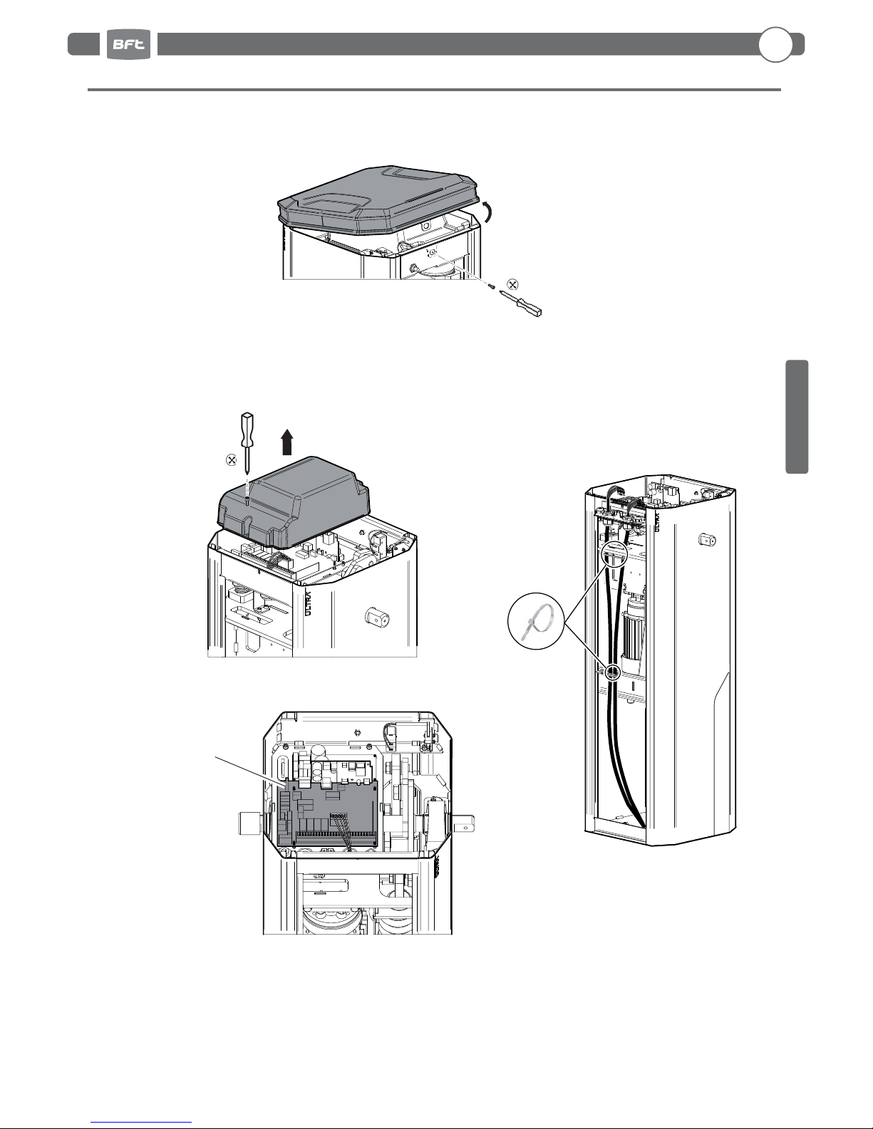
Open the cover and access inside the barrier
to remove of the doors
Refer to the use and
installation manual
of the control unit
CSB-Xtreme
2.3 ELECTRICAL CONNECTIONS
Remove the cover of the
internal control unit
Secure with
cable ties
Control board
2. Installation
EN
Page 5

- 12 -
ENGLISH
Use the "START" command to bring
the bar to vertical position
Opening micros-
witch cam
Check that the bar is in
vertical position
ADJUST THE BAR VERTICALLY OPERATING
THE CAM OF THE OPENING LIMIT SWITCH.
Electrically connect the control unit (see CSB-Xtreme
instructions)
TO ALIGN THE BAR WITH THE ROAD
PAVING, OPERATE THE ADJUSTABLE BAR
HOLDER.
Use the "Start" command to bring
the bar in horizontal position
Check that the bar is in horizontal
position
2.4 BAR INSTALLATION
2.5 BAR ALIGNMENT
2 x 10 mm
Adjustable bar holder
M6x20
4.2x16
Ø14
Ø6x12
M5x8
Ø6
M14x70
Ø5
M14
Ø6
Ø14
M6
Installation is mandatory in XL con guration (supplied).
For STD version, it is optional (not supplied).
HYPHEN PS
2. Installation
EN
BOOM PS
Page 6

- 13 -
ENGLISH
For the value “A” see
TAB.1 page 37
A
45°
Check that the bar is balanced
at approximately 45° position.
If necessary, adjust again the
distance "A".
Bring the bar to verti-
cal position
2.6 BAR BALANCING
24 mm
22 mm
DO IT ONLY WITH THE BAR MOUNTED
AND POSITIONED VERTICALLY
Remove the screw which secures the lever
Before performing any task
on the equipment, cut o
the power supply.
2.7 OPTIONAL ITEMS
ADDITIONAL
LIMIT SWITCHES
2. Installation
EN
Page 7

- 14 -
ENGLISH
RELEASE CRANK
2.8 MANUAL OPERATION
Manual release
DO IT ONLY WHEN THE BAR IS MOUNTED
Before performing any task on the equipment, cut o the power supply.
2. Installation
EN
Page 8

- 15 -
ENGLISH
3.1 GENERAL SAFETY
• The barrier is intended exclusively for vehicle use. Indicate and delimit any walkways using a speci c sign.
• Keep children, people and objects out of the operating range of the automation, in particular during operation.
• For safety reasons and in compliance with the regulations in force, it is advisable to use the appropriate control
unit.
• The installation must be performed following the prescriptions contained in the attached sheet "GENERAL
INSTRUCTIONS FOR SAFETY".
• Electrical connections must be carried out in compliance with the laws in force.
• The installer must instruct the user about the correct operation of the automatism, the manual emergency
operation, and the possible risks during operation.
• Perform risk assessment taking appropriate measures to eliminate them as prescribed by the machinery directive
2006/42/EEC, installing the safety devices.
• Before performing any task on the equipment, cut o the power supply using a cut-o switch.
• Cleaning and maintenance intended to be performed by the user must not be carried out by children without
supervision
3.2 NOTICES
The good operation of the automation is guaranteed only if the data reported in this manual is respected.
The Company is not liable for damage caused by failure to observe the rules of installation and the directions given in this manual.
The descriptions and illustrations in this manual are not binding. Leaving unchanged the essential characteristics of the product, the Company reserves the right to make at any time any changes which it considers
useful to improve in technical, construction and commercial terms the product, without committing itself
to update this publication.
3.3 USE
• Strictly follow the directions contained in the attached sheet "GENERAL INSTRUCTIONS FOR SAFETY".
• In the event of manual emergency operation, follow the directions outlined in item 2.8.
• Refer to the use and installation manual of the control unit.
3.4 ROUTINE MAINTENANCE (EVERY SIX MONTHS)
• Maintenance must only be performed by quali ed personnel.
• Record the on site servicing tasks in the form at page 38.
1
Check the condition of the barrier structure.
2
Check the condition of the bar clamping.
3
Check the condition of the spring, of the chain and of its anchors.
4
Check bar balance.
5
Check that at run end the bar is horizontal and/or vertical
6
Check the operation of the control unit and of the safety devices
7
Monitor the manual emergency operation.
3. Use and maintenance
EN
Page 9

- 37 -
1
2
3
A
Spring coupling holes
Do not weigh the arm down by applying other accessories
TA B. 1
Springs calibration (APPROXIMATE DATA)
REV.01
85
45
L
The values in the table are the same for the version with lights.
BTM-SKIRT
ADJ-FOOT
Special spring included in version XL. In these confi gurations, it is mandatory the installation of the bar reinforcement HYPHEN PS (see chap. 2.4 ref. )
ESDEFRENIT
MAXIMA ULTRA 36 •
BALANCING THE ARM
BOOM PS
BOOM PS
L 2000 2500 3000 3500 4000 4500 5000 5500 6000
BOOM PS
POSITION 1 1 1 1 1 2 2 3 3
A (mm) 130 125 110 90 125 115 100 120 105
BOOM PS
+ ADJ-FOOT
POSITION / 1 1 2 2 2 3 3
2
A (mm) / 110 90 125 115 100 125 110
95
BOOM PS
+ BTM-SKIRT
POSITION / 1 1 2 2 3 3
3
3
A (mm) / 110 85 120 100 120 105
125
115
BOOM PS
+ BTM-SKIRT
+ ADJ-FOOT
POSITION / 1 2 2 3 3 3
3
3
A (mm) / 95 120 105 125 110 95
120
105
Page 10

Dati impianto / Installation data
Installatore
Installer
Cliente
Customer
Matricola
Serial number
Data installazione
I
nstallation date
Data attivazione
Activation date
Luogo
Location
Dati manutenzione / Maintenance date
Nr. Data • Date Descrizione intervento • Intervention description Firma • Signature
1
Tecnico • Technician
Cliente • Customer
2
Tecnico • Technician
Cliente • Customer
3
Tecnico • Technician
Cliente • Customer
4
Tecnico • Technician
Cliente • Customer
5
Tecnico • Technician
Cliente • Customer
6
Tecnico • Technician
Cliente • Customer
7
Tecnico • Technician
Cliente • Customer
8
Tecnico • Technician
Cliente • Customer
- 38 -
REGISTRO DI MANUTENZIONE
MAINTENANCE LOG
REGISTRE DES OPÉRATIONS D’ENTRETIEN
INSTANDHALTUNGSPLAN
RESISTRO DE MANTENIMIENTO
Page 11

Nr. Data • Date Descrizione intervento • Intervention description Firma • Signature
9
Tecnico • Technician
Cliente • Customer
10
Tecnico • Technician
Cliente • Customer
11
Tecnico • Technician
Cliente • Customer
12
Tecnico • Technician
Cliente • Customer
13
Tecnico • Technician
Cliente • Customer
14
Tecnico • Technician
Cliente • Customer
15
Tecnico • Technician
Cliente • Customer
16
Tecnico • Technician
Cliente • Customer
17
Tecnico • Technician
Cliente • Customer
18
Tecnico • Technician
Cliente • Customer
19
Tecnico • Technician
Cliente • Customer
20
Tecnico • Technician
Cliente • Customer
21
Tecnico • Technician
Cliente • Customer
- 39 -
Page 12

ITALY
INSTALLATORE
INSTALLER
INSTALLATEUR
INSTALLATEUR
INSTALATOR
DA TA
DATE
DATE
DATUM
FECHA
 Loading...