


RR50 CC ENDURO / ENDURO STD / MOTARD / MOTARD STD / FACTORY / TRACK
Thanks for you preference, and have a good time! This handbook contains the information you need to properly operate and maintain your motorcycle.
The data and specifi cations provided in this manual does not constitute an engagement on the part of BETAMOTOR S.p.A. BETAMOTOR reserves the right to make any changes and improvements to its models at any moment and without notice.
1 |
GB |
|

IMPORTANT
We recommend you to check all the tightenings after the fi rst one or two hours’ ride over rough ground. Special attention should be paid to the following parts:
•rear sprocket
•ensure that the footrests are properly fi xed
•front/rear brake levers/calipers/discs
•check that the plastics are properly fastened
•engine bolts
•shock absorber bolts/swingarm
•wheel hubs/spokes
•rear frame
•pipe connections
•tensioning the chain
IMPORTANT
For any servicing requirements, please get in contact with Betamotor’s authorized service network.
GB |
2 |
|

Operating instructions.............................................................................. |
5 |
Ecologic guide....................................................................................... |
5 |
Riding safety.......................................................................................... |
6 |
CHAPTER 1 GENERAL INFORMATION.............................................. |
7 |
Vehicle identifi cation data ........................................................................ |
8 |
Familiarizing with your vehicle .................................................................. |
9 |
Controls.............................................................................................. |
10 |
Digital RPM indicator operating instructions ............................................... |
12 |
Keys .................................................................................................. |
18 |
Steering lock ....................................................................................... |
18 |
Specifi cations ...................................................................................... |
20 |
Wiring diagrams RR 50 ........................................................................ |
24 |
Recommended lubricants and liquids........................................................ |
26 |
CHAPTER 2 OPERATION ................................................................. |
27 |
Checks and maintenance before and after use........................................... |
28 |
Running-in ........................................................................................... |
28 |
Refuelling ............................................................................................ |
29 |
Starting the engine................................................................................ |
30 |
CHAPTER 3 CHECKS AND MAINTENANCE..................................... |
31 |
Gearbox oil ........................................................................................ |
32 |
Brake pump oil .................................................................................... |
33 |
Air fi lter .............................................................................................. |
34 |
Spark plug .......................................................................................... |
35 |
Front brake.......................................................................................... |
36 |
Rear brake .......................................................................................... |
36 |
Coolant .............................................................................................. |
37 |
Operations after cleaning ...................................................................... |
37 |
Scheduled maintenance......................................................................... |
38 |
CHAPTER 4 ADJUSTMENTS............................................................. |
39 |
Brake adjustment ................................................................................. |
40 |
Clutch lever adjustment .......................................................................... |
40 |
Idling setting........................................................................................ |
41 |
Adjustment of gas clearance................................................................... |
41 |
Checking and adjusting the steering play.................................................. |
41 |
Tensioning the chain.............................................................................. |
42 |
Adjusting the fork.................................................................................. |
43 |
Adjusting the shock absorber .................................................................. |
44 |
3
INDEX
GB

CHAPTER 6 TROUBLESHOOTING.................................................... |
45 |
Troubleshooting .................................................................................... |
46 |
INDEX.............................................................................................. |
47 |
INDEX
GB |
4 |
|

OPERATING INSTRUCTIONS
•The vehicle must be accompanied by: number-plate, registration document, tax disc and insurance.
•Do not carry animals, pets or loose objects that can stick out from the vehicle.
•Riding without a crash helmet is forbidden.
•Always ride with the low beam on.
•Any modifi cations of the engine or other parts resulting in a power and/or speed increase are punishable by severe sanctions including the confiscation of the vehicle.
•To protect your safety and that of others, always drive carefully and with your helmet on.
WARNING
Any modifi cations and tampering with the vehicle during the warranty period exempt the manufacturer from all responsibility and invalidate warranty.
ECOLOGIC GUIDE
•Every vehicle powered by an internal combustion engine produces an amount of noise (noise pollution) and gases (air pollution) which varies with the riding style.
•The abatement of noise and air pollution levels is the duty of everybody. Avoid full-throttle starts, sudden acceleration and abrupt braking. This will reduce noise emission as well as the wear and tear of the tyres and mechanical parts, and will also allow a considerable reduction in fuel consumption.
5 |
GB |
|

RIDING SAFETY
•Observe the Highway Code.
•Always put on and fasten a homologated helmet.
•Always ride with the low beam on.
•Always keep the crash helmet visor clean.
•Avoid wearing garments with hanging ends.
•Do not keep sharp or brittle objects in your pockets while riding.
•Properly adjust the rearview mirrors.
•Always ride in a seated position, with both hands on the handlebars and both feet on the footrests.
•Always pay attention and do not allow anything to distract you while riding.
•Do not eat, drink, smoke, use a mobile phone, etc. while riding.
•Do not wear headphones to listen to music while riding.
•Never ride abreast with other vehicles.
•Do not tow and avoid being towed by other vehicles.
•Always keep a safe distance from other vehicles.
•Do not sit on the vehicle when it is on its stand.
•Do not start off while the vehicle is on its stand.
•Do not pull out the stand when the vehicle is facing downhill.
•Avoid swaying and wheelies as they are extremely dangerous for your own and other people’s safety as well as for your vehicle.
•Always apply both brakes on dry roads with no gravel and sand. Using one brake may be dangerous and cause uncontrolled skidding.
•To reduce the braking distance, always apply both brakes.
•On wet roads and in off-road riding, drive with care and at moderate speed. Take special care in applying the brakes.
•Do not start the engine in closed places.
GB |
6 |
|

CONTENTS
CHAPTER 1 GENERAL INFORMATION
Vehicle identification data
Familiarizing with your vehicle
Controls
Digital RPM indicator operating instructions Specifications
Wiring diagram
Recommended lubricants and liquids
1
GENERAL INFORMATION
7 |
GB |
|
1
GENERAL INFORMATION
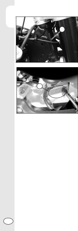
VEHICLE IDENTIFICATION DATA
FRAME IDENTIFICATION
A
Frame identifi cation data A are stamped on the right side of the steering head tube.
ENGINE IDENTIFICATION
Engine identifi cation data B are stamped on the l.h. side half crankcase.
B
WARNING:
Tampering with the identifi cation numbers is severely punished by law.
GB |
8 |
|

FAMILIARIZING WITH THE VEHICLE |
1 |
|
1
2
10
3
4
8
5 |
6 |
9
7
Main parts: |
8 |
Muffl er |
|
1 |
Tank cap |
||
2 |
Air fi lter |
9 |
Silencer |
3 |
Side stand |
10 Mixer oil tank cap |
|
4 |
Fuel cock |
|
(not fi tted on Factory version) |
5Fuel tank
6Radiator cap
7Kick-starter
GENERAL INFORMATION
9 |
GB |
|
1
GENERAL INFORMATION
5 2
1
3 |
6 |
4 |
|
|
8
7
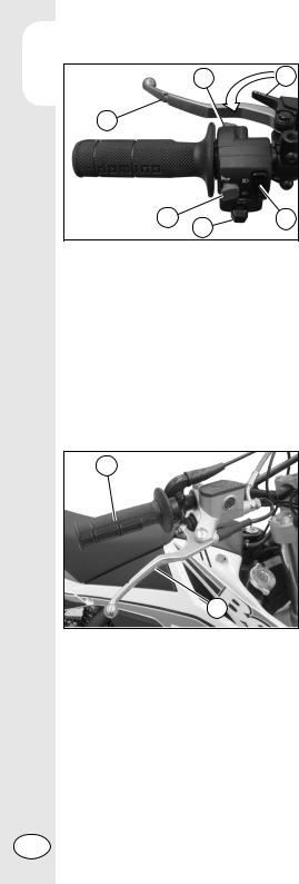
CONTROLS
CLUTCH LEVER
The clutch lever 1 is located on the left side of the handlebar. See the Adjustments chapter to adjust.
STARTER
The starter lever 2 is located on the left side of the handlebar. Turn the lever counterclockwise to operate.
SWITCH
The dip and service switch is located on the left side of the handlebar and is composed as follows:
3 Horn button;
4 Dip switch
(  high beam ;
  low beam)
5Shut-down;
6Turn signal light switch
FRONT BRAKE LEVER AND GAS CONTROL
The front brake lever 7 and the gas throttle 8 are located on the right side of the handlebar.
GB |
10 |
|
GEARCHANGE LEVER
Gearchange lever A is fitted to the left side of the engine.
The positions corresponding to the different gears are shown in the fi gure.
BRAKE PEDAL
Brake pedal 9 is located in front of the right-hand footrest.
KICKSTART
The kick-starter pedal 10 is located on the right side of the engine. The upper part is rotatable. To start, depress the kick-starter outward and with a quick movement downward. The pedal will automatically return upwards. After starting, manually fold the pedal in the rest position.
5 6
4
3
2
1 |
A |
|
9 |
10 |
1
GENERAL INFORMATION
11 |
GB |
|
1DIGITAL RPM INDICATOR OPERATING INSTRUCTIONS
Series RR 50 Enduro - Enduro standard - Factory - Motard - Motard standard - Track CONTENTS
GENERAL INFORMATION
1 GENERAL SPECIFICATIONS AND GENERAL INFORMATIONS
1.1General specifi cations
1.2General informations
2 SETTING THE PARAMETERS
2.1Setup sequence
2.1.1Selecting the unit of measure
2.1.2Selecting the wheel size
2.1.3Selecting the clock format
2.1.4Setting the Time
2.1.5Selecting the maintenance memo
3 SCREENS
4 FEATURES
5 SPEEDOMETER
6 ADJUSTING THE TRAVELLED DISTANCE METER
7 WARNING LIGHTS
1 GENERAL SPECIFICATIONS AND GENERAL INFORMATIONS
1.1 GENERAL SPECIFICATIONS
SPEED/DISTANCE SENSOR: Non-contact magnetic DISPLAY MEASUREMENTS: 125mm x 41mm x 34mm STORAGE TEMPERATURE: -20°C to 80°C (-4°F to 176°F) BATTERY: 3V CR2032
BATTERY LIFE: Approximately one year EXTERNAL CURRENT SUPPLY: 12V DC
2 |
1 |
3 |
6 |
4 |
5 |
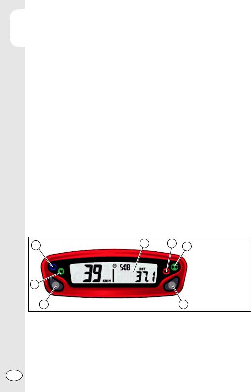
1 |
LCD |
|
|
2 |
High beam light |
|
|
3 |
Idle pilot light |
|
|
4 |
Oil tank level light |
|
|
5 |
Indicator light |
|
|
6 |
Push-button 1 |
|
|
7 |
Push-button 2 |
7 |
1.2 GENERAL INFORMATIONS
Backlight:
The digital speedometer/odometer is backlit to enable reading where there is poor or no lighting.
When using supplied power with the engine on:
• The back-lighting is on permanently when the engine is running.
GB |
12 |
|

Using only the internal battery:
•With the LO symbol, the backlighting will not switch on. The symbol appears when the battery voltage is lower than 2.45V.
Reset Button:
Using the Reset button, located on the back of the instrument, all travel data will be deleted, including date and time.
Internal battery:
The instrument houses a 3.0V internal button cell battery (CR2032). The instrument can only work with this battery. The symbol appears when the battery is running low. To change the battery, unscrew the cap located on the back of the instrument using a coin.
Once the battery has been changed, make sure that the positive side is facing outwards.
REPLACE THE BATTERY WITH ANOTHER CR2032-TYPE BATTERY.
2 SETTING THE PARAMETERS
General information:
Allowed settings:
•Km/h (kilometres per hour) or M/h (Miles per hour)
•Wheel size (rolling circumference) [mm]
•Clock format: 12-hour / 24-hour
•Current date
•Maintenance
TO ENTER THE PARAMETER SETTINGS MODE HOLD DOWN THE RIGHT AND LEFT BUTTONS FOR APPROX. 3s.
THE WORD “Unit” WILL FLASH ON THE DISPLAY.
The operational logic is structured as follows:
•The instrument enters SETUP mode displaying the parameters according to the sequence listed above.
•The instrument displays the parameter to be changed for a few seconds in fl ash mode.
•If you wish to change the parameter displayed for those few seconds simply edit the values by pressing the right and/or left buttons (according to the modes listed below), otherwise wait a few seconds (approx. 5 s) to proceed to the next parameter.
•When the parameter has been edited to the desired value, the instrument automatically moves onto the next setting, there is no need to press any button of confi rmation.
•If you only wish to enter the setup mode to view the confi gured settings, simply wait without pressing any buttons; the instrument will display all of the set parameters and will then automatically go back to “Normal Mode”.
1
GENERAL INFORMATION
13 |
GB |
|

12.1 SETUP SEQUENCE
GENERAL INFORMATION
Select unit of measure
Wheel size
Clock format
Setting the Time
Maintenance reminder
2.1.1 Selecting the unit of measure (Km/h or M/h):
TO SELECT THE UNIT OF MEASURE (Km/h or M/h), PRESS THE RIGHT OR LEFT BUTTON.
WAIT 5 SECONDS TO PROCEED TO THE NEXT SETTING. DO NOT PRESS ANY BUTTONS.
2.1.2 Selecting the wheel size (rolling circumference):
The instrument has programmed two rolling circumference measurements for the front wheel: larger size (Enduro version - 21” rim) or smaller size (Motard version – 17” rim). PRESS THE LEFT BUTTON TO SELECT ONE OF THE TWO OPTIONS.
WAIT 5 SECONDS TO PROCEED TO THE NEXT SETTING. DO NOT PRESS ANY BUTTONS.
2.1.3 Selecting the clock format (12or 24-hour):
The default setting on the instrument is the 12-hour clock.
TO SELECT THE 12OR 24-HOUR CLOCK, PRESS THE RIGHT OR LEFT BUTTON. WAIT 5 SECONDS TO PROCEED TO THE NEXT SETTING. DO NOT PRESS ANY BUTTONS.
2.1.4 Setting the Time:
The time is set by increasing or decreasing it by 1 minute steps. PRESS THE LEFT BUTTON TO DECREASE THE TIME.
PRESS THE RIGHT BUTTON TO INCREASE IT.
WAIT 5 SECONDS TO PROCEED TO THE NEXT SETTING. DO NOT PRESS ANY BUTTONS.
2.1.5 Selecting the maintenance reminder
The instrument displays the countdown to maintenance operations based on the data entered by the user. The data is based on the kilometres and miles travelled according to the unit of measure selected by the user. The factory setting is on “OFF”.
PRESS THE LEFT BUTTON TO LOWER THE NUMBER. PRESS THE RIGHT BUTTON TO RAISE IT (max value 10000Km).
WAIT 5 SECONDS TO EXIT SETUP MODE. DO NOT PRESS ANY BUTTONS.
GB |
14 |
|

3 SCREENS
Switching between 3 normal modes
All of the information that the instrument is capable of providing is displayed on one of these 3 screens.
The instrument will stay on the set screen until a button is pressed to switch to another screen.
TO SWITCH FROM ONE SCREEN TO ANOTHER, PRESS EITHER THE RIGHT OR LEFT BUTTON BRIEFLY.
Screen 1:
•Speed • Distance 1 (DST) • Time Screen 2:
•Speed • Distance 2 (DST2 ) • Time Screen 3:
•Maximum speed (MAX) • Average speed (AVG)
•Accumulated running time (ART) • Odometer (ODO)
*Note: The maximum and average speeds are updated automatically when the user accesses screen 3.
4 FEATURES
General information:
During normal use the instrument is in “Normal” mode.
Available modes:
•Sleep Mode
•Choose from 3 “Normal” screens
•Clear Distance 1 (DST1)
•Clear Distance 2 (DST2)
•Clear Maximum/Average Speed (MAX/AVG)
Sleep Mode:
If the instrument does not receive any input for 5 minutes (either from the movement of the wheel or a button), it will go into “Sleep Mode”. In “Sleep Mode” only the time appears on the screen.
To exit “Sleep Mode” all the instrument requires is an input, either from the movement of the sensor or by pressing a button.
1
GENERAL INFORMATION
15 |
GB |
|
 Loading...