


1936/4A
Beta
1936/4A
1936/5A
Manuale d'uso ed istruzioni
I
Operation manual and instructions
GB
Notice d'utilisation et instructions
F
Gebruikshandleiding
NL
Bedienungsanleitung
D
Manual de uso e instrucciones
E
Manual de uso e instruções
P
Bruksanvisning
S
Käyttöohjeet
SF
Brugsmanual
DK
Bruksveiledning
N
Használati kézikönyv és útmutató
H
Kullanım ve Talimat Kılavuzu
TR
Instrukcja obsługi i zalecenia
PL
Beta
1936/4A - 1936/5A
➀
➂
➄➅
➁
➃
➆➇

Beta
MANUALE D’USO ED ISTRUZIONI PER SMERIGLIATRICI ANGOLARI PRODOTTI DA:
BETA UTENSILI S.P.A.
Via A. Volta 18,
20845, Sovico (MB)
ITALIA
ocumentazione redatta originariamente in lingua ITALIANA.
D
ATTENZIONE
IMPORTANTE LEGGERE COMPLETAMENTE IL PRESENTE MANUALE PRIMA DI UTILIZZARE
L’UTENSILE PNEUMATICO. IN CASO DI MANCATO RISPETTO DELLE NORME DI SICUREZZA E
DELLE ISTRUZIONI OPERATIVE, POSSONO VERIFICARSI SERI INFORTUNI.
Conservare accuratamente le istruzioni di sicurezza e consegnarle al personale utilizzatore.
DESTINAZIONE D’USO
– La smerigliatrice angolare pneumatica è destinata al seguente uso:
• levigare superfici metalliche, in legno o in pietra
• asportare bave su metalli
• tagliare metalli, legno o pietre
• è possibile l’impiego della smerigliatrice anche in luoghi aperti esposti ad acqua e aria
– Non sono consentite le seguenti operazioni:
• è vietato l’utilizzo di mole con diametro e impiego diverso da quello prescritto
• è vietato l’uso in ambienti contenenti atmosfere potenzialmente esplosive
• è vietato bloccare il pulsante di azionamento con nastro adesivo o fascette
SICUREZZA DELLA POSTAZIONE DI LAVORO
– Prestare attenzione alle superfici che possono diventare scivolose a causa dell’uso della macchina e al pericolo di inciampamento
nel tubo flessibile dell’aria.
– Durante l’utilizzo dell’utensile pneumatico per lavori eseguiti in quota, adottare tutte le misure preventive atte ad eliminare o
minimizzare i rischi ad altri lavoratori, conseguenti a possibili cadute accidentali dell’attrezzatura (per esempio mediante
segregazione dell’area di lavoro, adeguata segnalazione, ecc.).
Non utilizzare l’utensile pneumatico in ambienti contenenti atmosfere potenzialmente esplosive perché possono svilupparsi scintille
in grado di incendiare polveri o vapori.
Evitare il contatto con apparecchiature in tensione in quanto l’utensile pneumatico non è isolato. Il contatto con elementi in tensione
può causare una scossa elettrica.
Al fine di rilevare linee di alimentazione nascoste, utilizzare adatte apparecchiature di ricerca oppure rivolgersi alla locale società
erogatrice. Un contatto con linee elettriche può provocare lo sviluppo di incendi e di scosse elettriche. Danneggiando le linee del
gas si crea il pericolo di esplosioni. Penetrando una tubazione dell’acqua si provocano seri danni materiali.
Impedire che bambini o visitatori possano avvicinarsi alla postazione di lavoro mentre si sta operando con l’utensile pneumatico. La
presenza di altre persone provoca distrazione che può comportare la perdita del controllo sull’utensile pneumatico.
SICUREZZA DEGLI UTENSILI PNEUMATICI
– Non puntare mai il flusso d’aria verso se stessi o verso altre persone. L’aria compressa può causare lesioni.
– Controllare i raccordi di collegamento e le tubazioni di alimentazione. Tutti i gruppi, i giunti e i tubi flessibili devono essere installati
conformemente ai dati tecnici relativi a pressione e flusso d’aria. Una pressione troppo bassa pregiudica il funzionamento
dell’utensile pneumatico, una pressione alta può causare danni e/o lesioni.
– Evitare di piegare o stringere i tubi flessibili, evitare l’uso di solventi e di spigoli taglienti. Proteggere i tubi da calore, olio e parti
rotanti. Sostituire immediatamente un tubo flessibile danneggiato. Una tubazione di alimentazione difettosa può provocare
movimenti incontrollati del tubo dell’aria compressa. Polveri oppure trucioli sollevati dall’aria possono provocare lesioni agli occhi.
Accertarsi che le fascette per tubi flessibili siano sempre ben fissate.
I

NDICAZIONE PER LA SICUREZZA DEL PERSONALE
I
– Si raccomanda la massima attenzione avendo cura di concentrarsi sempre sulle proprie azioni. Non utilizzare l’utensile pneumatico
in caso di stanchezza o sotto l’effetto di droghe, bevande alcoliche o medicinali.
Utilizzare sempre i seguenti dispositivi individuali di protezione:
–
• occhiali di protezione
• scarpe di sicurezza
• otoprotettori
• guanti di protezione per agenti fisici
guanti antivibrazione, da utilizzare a seguito di specifica analisi del livello di esposizione giornaliera alle vibrazioni per sistema
•
mano-braccio
Avere cura di mettersi in posizione sicura mantenendo l’equilibrio in ogni momento. Una posizione di lavoro sicura ed un’adatta
–
postura del corpo permettono di poter controllare meglio l’utensile pneumatico in caso di situazioni inaspettate.
Non indossare vestiti larghi. Non portare bracciali e catenine. Tenere capelli, vestiti e guanti lontano da parti in movimento. Vestiti
–
larghi, gioielli o capelli lunghi possono impigliarsi nelle parti in movimento.
– Non respirare direttamente l’aria di scarico, evitando che possa arrivare agli occhi. L’aria di scarico dell’utensile pneumatico può
ontenere acqua, olio, particelle metalliche ed impurità. Questi elementi possono provocare pericoli.
c
– Non utilizzare mai la smerigliatrice angolare senza l’apposito riparo, adeguatamente fissato ed orientato.
Non appoggiare mai la smerigliatrice angolare prima che la mola sia completamente arrestata.
–
UTILIZZO ACCURATO DELLA SMERIGLIATRICE ANGOLARE PNEUMATICA
Per bloccare e supportare il pezzo in lavorazione utilizzare dispositivi di serraggio oppure morse. Non tenere il pezzo in lavorazione
–
con una mano o bloccato con il corpo: così facendo non è più possibile operare in sicurezza.
Non sottoporre l’utensile pneumatico a sovraccarico. Effettuare i propri lavori utilizzando l’utensile pneumatico esclusivamente per il
–
caso previsto.
Verificare sempre l’integrità della macchina. Non utilizzare alcun utensile pneumatico il cui interruttore di avvio/arresto sia difettoso.
–
Un utensile pneumatico che non può più essere arrestato o avviato è pericoloso e deve essere riparato.
– Interrompere sempre l’alimentazione dell’aria prima di effettuare operazioni di regolazione sulla smerigliatrice, prima di sostituire
accessori oppure nel caso in cui lo stesso non venga utilizzato. Questa misura preventiva impedisce l’avvio accidentale
dell’utensile pneumatico.
– Togliere gli utensili di regolazione prima dell’utilizzo della smerigliatrice angolare in quanto possono essere proiettati ad elevata
velocità.
– Quando gli utensili pneumatici non vengono utilizzati, conservarli al di fuori del raggio di accesso dei bambini. Non permettere di
usare l’utensile pneumatico a persone che non abbiano letto le presenti istruzioni.
– Effettuare accuratamente la verifica dell’utensile pneumatico, accertandosi che parti mobili dell’utensile funzionino perfettamente,
che non si inceppino e che non vi siano pezzi rotti o danneggiati al punto da pregiudicarne il funzionamento. Far riparare le parti
danneggiate prima dell’impiego dell’utensile pneumatico.
– Verificare che il riparo della smerigliatrice sia integro e fissato correttamente, orientandolo in modo da evitare che il flusso di
scintille sia direzionato verso l’operatore. La regolazione può essere effettuata premendo la leva “sgancio rapido” posta
anteriormente (immagine 2-r).
– Controllare che la flangia sia in buone condizioni, non presenti incrinature, bave ecc. Accertarsi che l’albero e le relative filettature
non siano danneggiate o usurate.
– Prima di ogni utilizzo verificare che la mola sia in buone condizioni e idonea al tipo di lavorazione da eseguire. Non deve
presentare danneggiamenti, scheggiature, crepe, ecc. Una volta eseguito il controllo, avviare l’utensile pneumatico per un minuto al
numero di giri massimo.
– Accertarsi che non vi siano altre persone nelle vicinanze.
– Periodicamente verificare che la velocità della smerigliatrice angolare non sia maggiore di quella indicata dal fornitore. Questa
verifica deve essere eseguita senza montaggio della mola.
– Al momento dell’arresto porre la smerigliatrice in una posizione stabile e sicura. L’arresto della mola non è immediato.
– Utilizzare esclusivamente mole idonee per l’attività prevista, come ad esempio:
• mole per levigare superfici metalliche, in legno o in pietra
• mole per asportare bave su metalli
• mole per tagliare metalli, legno o pietre
– L’utensile pneumatico non deve essere modificato. Le modifiche possono ridurre l’efficacia delle misure di sicurezza ed aumentare i
rischi per l’operatore.
– Far riparare l’utensile pneumatico solo ed esclusivamente da personale specializzato. Utilizzare pezzi di ricambio originali.

NDICAZIONI DI SICUREZZA PER LA SMERIGLIATRICE ANGOLARE PNEUMATICA
I
– Controllare se la targhetta di identificazione è leggibile. In caso negativo procurarsi la targhetta per la sostituzione dal produttore.
– La smerigliatrice angolare pneumatica si può fermare se:
l’utensile pneumatico viene sovraccaricato
•
• la mola da taglio rimane bloccata nel pezzo in lavorazione
– Nel caso di bloccaggio della mola arrestare immediatamente la smerigliatrice mantenendola inattiva fino al completo sbloccaggio
della mola stessa. Non tentare di estrarre la mola ancora in funzione. Prima di riprendere qualsiasi attività verificare che la mola
non sia danneggiata e che sia fissata correttamente.
Possono essere scagliati dei pezzi ad elevata velocità nel caso di rottura del pezzo in lavorazione o della mola.
–
– Fare molto attenzione alle scintille di smerigliatura in quanto possono essere fonte di potenziali pericoli per le cose e per le
ersone che ne sono esposte. Possono incendiare indumenti e provocare ustioni.
p
– L’operatore ed il personale addetto alla manutenzione devono essere in grado di gestire fisicamente il peso e la potenza
ell’utensile pneumatico.
d
– E’ importante essere preparati a movimenti inaspettati della smerigliatrice dovuti al bloccaggio o alla rottura della mola da taglio.
Tenere sempre ben salda la smerigliatrice angolare e portare il corpo e le braccia in una posizione tale da permettere di
ompensare questi movimenti.
c
– Non avvicinare mai la mano alla mola: ci si può ferire.
Assicurarsi che il senso di rotazione della smerigliatrice angolare sia consono alla mola utilizzata.
–
– Arrestare l’utensile nel caso di interruzione dell’alimentazione dell’aria oppure di una pressione di esercizio ridotta. Controllare la
pressione d’esercizio e, a pressione d’esercizio ottimale, avviare di nuovo.
Durante l’utilizzo dell’utensile pneumatico è possibile che l’operatore provi sensazioni fastidiose a mani, braccia, spalle e nell’area
–
del collo. Assumere una posizione comoda cambiando la postura può aiutare ad evitare fastidi ed affaticamento.
Attenzione nel caso di funzionamento prolungato dell’utensile pneumatico: parte dell’utensile stesso e l’accessorio da taglio
ossono diventare caldi. Utilizzare idonei guanti di protezione per agenti fisici.
p
Pericoli dovuti a polveri e fumi: in funzione della tipologia del materiale lavorato, i fumi generati durante l’utilizzo dell’utensile
pneumatico possono causare patologie alla salute delle persone. E’ necessaria un’adeguata indagine di igiene ambientale per
stabilire l’esatta assegnazione del tipo e del grado del dispositivo di protezione individuale da utilizzare per le vie respiratorie.
Durante l’utilizzo dell’utensile pneumatico sul pezzo da lavorare si generano rumori, a volte anche nocivi, per il personale esposto.
E’ necessaria un’adeguata indagine fonometrica per stabilire l’esatta assegnazione dello specifico dispositivo di protezione
individuale dell’udito (otoprotettore) da utilizzare.
Se da specifica indagine eseguita risulta che l’esposizione giornaliera alle vibrazioni generata durante l’utilizzo dell’utensile
pneumatico supera il valore limite di azione prevista dalla normativa vigente nel rispettivo Paese, si devono utilizzare specifici
guanti antivibrazione.
– Qualora doveste accorgervi che la pelle delle dita diventa intorpidita o bianca, presenta formicolio o dolore, sospendere il lavoro
con l’utensile pneumatico. Informare il datore di lavoro e consultare un medico.
– Non far sobbalzare la mola sul pezzo in lavorazione: questo può causare un sensibile aumento delle vibrazioni.
– Tenere l’utensile pneumatico con una presa non eccessivamente salda ma sicura, considerando le necessarie forze di reazione
della mano.
– Non trasportatore mai l’utensile pneumatico tenendolo per il tubo flessibile.

ISPOSITIVI DI PROTEZIONE INDIVIDUALI PREVISTI DURANTE L’UTILIZZO DELL’UTENSILE PNEUMATICO
D
La mancata osservanza delle seguenti avvertenze può causare lesioni fisiche e/o patologie.
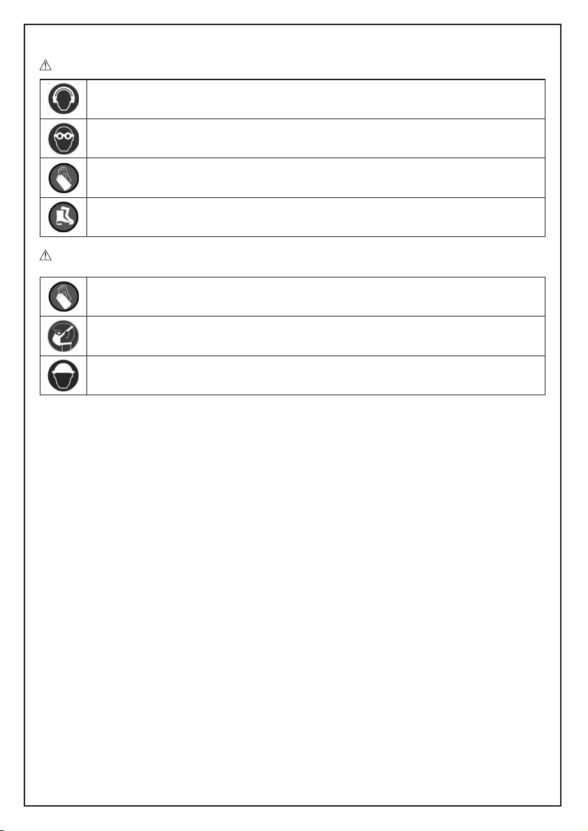
INDOSSARE SEMPRE DISPOSITIVI OTOPROTETTORI QUANDO SI ADOPERA L’UTENSILE
NEUMATICO
P
INDOSSARE SEMPRE GLI OCCHIALI PROTETTIVI QUANDO SI ADOPERA L’UTENSILE
PNEUMATICO O QUANDO SI ESEGUE L’ATTIVITÀ DI MANUTENZIONE
UTILIZZARE SEMPRE GUANTI DI PROTEZIONE PER AGENTI FISICI DURANTE L’UTILIZZO
DELL’UTENSILE PNEUMATICO
UTILIZZARE SEMPRE CALZATURE DI SICUREZZA
Ulteriori dispositivi di protezione individuali da utilizzare in funzione dei valori riscontrati nell’indagine di igiene ambientale/analisi
rischi nell’eventualità che i valori superino i limiti previsti dalle vigenti normative.
UTILIZZARE GUANTI ANTIVIBRAZIONE DURANTE L’UTILIZZO DELL’UTENSILE PNEUMATICO A
SEGUITO DI SPECIFICA ANALISI DEL LIVELLO DI ESPOSIZIONE GIORNALIERA ALLE
VIBRAZIONI PER SISTEMA MANO-BRACCIO
UTILIZZARE MASCHERA DI PROTEZIONE PER AGENTI FISICI
UTILIZZARE CASCO DI PROTEZIONE
DATI TECNICI Art. 1936/4A Art. 1936/5A
DIAMETRO MOLA 115 mm 125 mm
FILETTATURA ALBERO M14 M14
VELOCITÀ A VUOTO 10000 giri/min 11000 giri/min
POTENZA 0.66 kW 0.66 kW
ATTACCO ARIA 1/4” GAS 1/4” GAS
PRESSIONE MASSIMA 6.2 Bar 6.2 Bar
DIAMETRO INT. MINIMO TUBO ARIA 10 mm 10 mm
CONSUMO D’DARIA MASSIMO 390 l/min 390 l/min
PESO 1,8 kg 1,9 kg
LUNGHEZZA TOTALE 238 mm 238 mm
LIVELLO PRESSIONE SONORA 84.0 dB(A) (EN ISO 15744) 89.0 dB(A) (EN ISO 15744)
LIVELLO POTENZA ACUSTICA 87.0 dB(A) (EN ISO 15744) 91.0 dB(A) (EN ISO 15744)
LIVELLO VIBRAZIONI 2.4 m/s
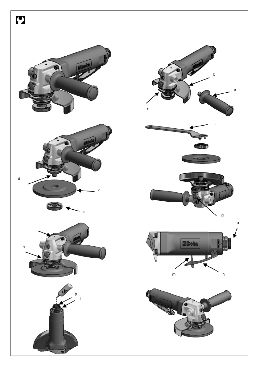
LEGENDA
a: impugnatura laterale h: indicazione senso di rotazione mola
b: riparo smerigliatrice i: ingrassaggio
c: mola l: scarico aria
d: flangia disco m: leva di sicurezza
e: flangia blocca disco n: leva avvio smerigliatrice
f: chiave con naselli tondi o: attacco aria 1/4” GAS
g: pulsante “spindle lock” p: lubrificazione olio
2
(ISO 28927-2) 2.4 m/s2(ISO 28927-2)
r: leva regolazione riparo smerigliatrice
ISTRUZIONI MONTAGGIO DISPOSITIVI
Montaggio dell’impugnatura laterale
Assemblare l’impugnatura laterale (immagine 2-a) avvitandola sulla testa della smerigliatrice angolare o girando la manopola stessa
(bloccandola manualmente). A seconda della posizione di lavoro l’impugnatura laterale può essere montata sia sul lato sinistro che
destro, in modo da assumere una posizione di lavoro di assoluta maneggevolezza e stabilità.
Collegamento alimentazione dell’aria
Per un utilizzo corretto dell’utensile pneumatico rispettare sempre la pressione massima di 6.2 bar, misurata all’ingresso dell’utensile.
Alimentare l’utensile pneumatico con aria pulita e priva di condensa (immagine 6-o). Una pressione troppo elevata o la presenza di
umidità nell’aria di alimentazione riducono la durata delle parti meccaniche e possono causare danni all’utensile.

TILIZZO
U
Avviamento / Arresto
er avviare la smerigliatrice angolare spingere in avanti la leva di sicurezza e contemporaneamente premere la leva di avviamento
P
(immagine 6-m,n). La leva di avviamento va tenuta premuta durante l’esecuzione del lavoro. Al rilascio della leva la smerigliatrice
angolare si arresta in un tempo inferiore a 5s.
La smerigliatrice è dotata di scarico dell’aria posteriore (immagine 7-l).
Al momento dell’arresto porre la smerigliatrice in una posizione stabile e sicura. L’arresto della mola non è immediato.
Inserimento/sostituzione mola
er il montaggio della mola sulla smerigliatrice angolare (immagine 3, 4) procedere nel seguente modo:
P
– bloccare manualmente il pulsante “spindle lock” (immagine 4-g). Allentare la flangia blocca disco dell’albero rotante porta mola,
nserendo nella flangia l’apposita chiave con naselli tondi e tenendo sempre bloccato il pulsante “spindle lock”. Quindi sfilare
i
completamente la flangia;
– inserire la mola per smerigliatrici posizionandola tra le due flange (flangia disco e flangia blocca disco). Accertarsi del corretto
enso di rotazione della mola. La smerigliatrice angolare prevede un solo senso di rotazione, senso orario (immagine 5);
s
– avvitare manualmente la flangia blocca disco, serrare la flangia utilizzando la chiave con naselli e tenendo bloccato l’albero rotante
on il pulsante “spindle lock”;
c
– controllare che la mola sia stata ben fissata.
Sostituire la mola della smerigliatrice angolare nel seguente modo:
Sbloccare la flangia blocca disco utilizzando la chiave con naselli tondi e tenendo bloccato l’albero rotante con il pulsante “spindle
–
lock”;
la mola è svincolata e può essere rimossa;
–
– inserire la nuova mola e procedere come sopra.
nterrompere sempre l’alimentazione dell’aria prima di effettuare operazioni di regolazione o inserimento mola. Questa misura
I
preventiva impedisce l’avvio accidentale dell’utensile pneumatico.
Durante l’utilizzo della smerigliatrice angolare E’ VIETATO premere il pulsante “spindle lock” perchè la flangia e relativa mola si
allentano sbloccandosi.
Lubrificazione/Ingrassaggio
E’ indispensabile collegare l’utensile pneumatico ad un gruppo filtro-lubrificatore di linea a micro nebbia (si consiglia l’articolo Beta
1919F1/4) regolato a due gocce al minuto. In questo caso si avrà una resa elevata con una ridotta usura delle parti meccaniche.
Nel caso la linea fosse sprovvista di lubrificazione, è necessario immettere direttamente nell’utensile pneumatico l’olio ISO 32,
attraverso il foro di alimentazione dell’aria (immagine 7-p).
E’ necessario inoltre effettuare periodicamente l’ingrassaggio della smerigliatrice angolare, attraverso l’ugello ingrassatore, utilizzando
grasso EP2 -b.
MANUTENZIONE
Gli interventi di manutenzione e di riparazione devono essere eseguiti solo ed esclusivamente da personale specializzato. Per tali
interventi potete rivolgervi al centro riparazioni di Beta Utensili S.P.A. attraverso il vostro rivenditore Beta di fiducia.
SMALTIMENTO
L’utensile pneumatico, gli accessori e gli imballaggi devono essere inviati ad un centro di raccolta smaltimento rifiuti, secondo le leggi
vigenti del Paese in cui vi trovate.
GARANZIA
Questo utensile è fabbricato e collaudato secondo le norme attualmente vigenti nella Comunità Europea ed è coperto da garanzia per
un periodo di 12 mesi per uso professionale o 24 mesi per uso non professionale.
Vengono riparati guasti dovuti a difetti di materiale o di produzione mediante il ripristino o la sostituzione dei pezzi difettosi a nostra
discrezione.
L’effettuazione di uno o più interventi nel periodo di garanzia non modifica la data di scadenza della stessa.
Non sono soggetti a garanzia difetti dovuti all’usura, all’uso errato od improprio, alle rotture causate da colpi e/o cadute. La garanzia
decade quando vengono apportate modifiche, quando l’utensile pneumatico viene manomesso o quando viene inviato all’assistenza
smontato.
Sono espressamente esclusi danni causati a persone e/o cose di qualsiasi genere e/o natura, diretti e/o indiretti.
Dichiariamo sotto la nostra piena responsabilità che il prodotto descritto è conforme a tutte le disposizioni pertinenti della Direttiva
DICHIARAZIONE DI CONFORMITÀ
Macchine 2006/42/CE e relative modifiche, nonché alla seguente normativa:
• EN ISO 11148-7
Il Fascicolo Tecnico è disponibile presso:
BETA UTENSILI S.P.A.
Via A. Volta 18 - 20845 Sovico (MB) - ITALIA
Nome e qualifica del Responsabile
MASSIMO CICERI
(Consigliere Delegato)
BETA UTENSILI S.P.A. Data 01/06/2015
Via A. Volta 18
20845 Sovico (MB)
ITALIA

Beta
GB
OPERATION MANUAL AND INSTRUCTIONS FOR ANGLE GRINDERS MANUFACTURED BY:
BETA UTENSILI S.P.A.
Via A. Volta 18,
20845, Sovico (MB)
ITALY
riginal documentation drawn up in ITALIAN.
O
CAUTION
IT IS IMPORTANT TO READ THIS MANUAL THOROUGHLY BEFORE USING THE PNEUMATIC
TOOL. FAILURE TO COMPLY WITH THE SAFETY STANDARDS AND OPERATING INSTRUCTIONS
MAY RESULT IN SERIOUS INJURY.
Store the safety instructions with care and hand them over to the users.
PURPOSE OF USE
– The air angle grinder can be used for the following purposes:
• smoothing metal, wood or stone surfaces
• removing burrs from metal
• cutting metal, wood or stone
• the grinder can also be used in open places exposed to water and air
– The air angle grinder must not be used for the following operations:
• no grinding wheels with any diameters and uses other than the established diameters and uses may be used
• the air angle grinder must not be used in environments containing potentially explosive atmospheres
• the trigger must not be locked with adhesive tape or clamps
WORK AREA SAFETY
– Beware of both surfaces that may become slippery due to the use of the machine and the danger of tripping over the air hose.
– While using the pneumatic tool for jobs performed high from the ground, take all necessary precautions, to eliminate or minimize
risk to other workers, following the accidental falling of any tools (for example, isolation of the work area and proper signs).
Do not operate the pneumatic tool in environments containing potentially explosive atmospheres, because sparks may be
generated, which can ignite the dust or fumes.
Avoid contact with live equipment, because the pneumatic tool is not insulated. Contact with live parts can cause electric shocks.
To find any hidden power supply lines, use suitable search tools or contact the local power supply company. Contact with electric
lines can cause fires and electric shocks. Damaging gas lines causes the risk of explosion. Penetrating a water pipe will result in
severe material damage.
Keep children and bystanders away from your workplace while operating the pneumatic tool. Distractions from other people can
cause you to lose control over the pneumatic tool.
PNEUMATIC TOOL SAFETY
– Do not point the air flow to yourself or other people. Compressed air can cause injury.
– Check the connections and the air supply lines. All units, couplers and hoses should conform to the product specifications in terms
of pressure and air volume. Too low pressure impairs the function of the pneumatic tool; too high pressure can cause damage
and/or injury.
– Do not bend or tighten any hoses; avoid using solvents and sharp edges. Keep the hoses away from heat, oil and rotating parts.
Immediately replace any damaged hose. A defective feed pipe may cause uncontrolled movements of the compressed air pipe.
Raised rust or chips may cause eye injury. Make sure that the hose clamps are always secured firmly.

ERSONNEL SAFETY
P
– Stay alert; watch what you are doing. Do not use the pneumatic tool while tired or under the influence of drugs, alcohol, or
medication.
Always use the following personal protective equipment:
–
• Eye protection;
• Safety shoes;
• Hearing protection;
• Protective gloves against physical agents;
Anti-vibration gloves, to be worn following a specially conducted survey of the daily exposure of the hand-arm system to
•
vibration.
Make sure you are in a safe position, keeping proper balance at all times. A safe working position and a proper body posture
–
enable better control of the pneumatic tool in unexpected situations.
Do not wear loose clothing or jewellery. Keep your hair, clothing and gloves away from moving parts. Loose clothing, jewellery, and
–
long hair can get caught in moving parts.
– Do not directly inhale the exhaust air, and prevent it from getting into your eyes. The exhaust air of the pneumatic tool can contain
ater, oil, metal particles and impurities, which may cause hazards.
w
– Do not use the angle grinder if its guard has not been properly fixed and positioned.
Do not place the angle grinder before the grinding wheel has stopped completely.
–
PNEUMATIC TOOL USE AND CARE
Use clamping devices or a vice to secure and support the workpiece. Holding the workpiece by hand or against your body will not
–
allow for safe operation of the pneumatic tool.
Do not overload the pneumatic tool. Use the pneumatic tool intended for your work.
–
– Always check that the machine is free from defects. Do not use a pneumatic tool that has a defective On/Off switch. A pneumatic
ool that can no longer be stopped or started is dangerous and must be repaired.
t
– Disconnect the air supply before making adjustments, changing accessories, or placing the pneumatic tool aside. This safety
measure prevents accidental starting of the pneumatic tool.
– Store idle pneumatic tools out of the reach of children. Do not allow persons unfamiliar with these instructions to operate the
pneumatic tool.
– Maintain the pneumatic tool with care. Check for misalignment or binding of moving parts, breakage of parts and any other
condition that may affect the operation of the pneumatic tool. Have damaged parts repaired before using the pneumatic tool.
– Keep cutting tools sharp and clean. Properly maintained cutting tools with sharp cutting edges are less likely to bind and are easier
to control.
– Do not modify the pneumatic tool. This can reduce the effectiveness of safety measures and increase operator risk.
– Have the pneumatic tool repaired only through a qualified repair person and only using original replacement parts.
AIR DRILL SAFETY
– Use clamping devices or a vice to secure and support the workpiece. Holding the workpiece by hand or against your body will not
allow for safe operation of the pneumatic tool.
– Do not overload the pneumatic tool. Use the pneumatic tool intended for your work.
– Always check that the machine is free from defects. Do not use a pneumatic tool that has a defective On/Off switch. A pneumatic
tool that can no longer be stopped or started is dangerous and must be repaired.
– Disconnect the air supply before making adjustments, changing accessories, or placing the grinder aside. This safety measure
prevents accidental starting of the pneumatic tool.
– Before using the angle grinder, remove the adjusting tools, since these may be projected at high speed.
– Store idle pneumatic tools out of the reach of children. Do not allow persons unfamiliar with these instructions to operate the
pneumatic tool.
– Maintain the pneumatic tool with care. Check for misalignment or binding of moving parts, breakage of parts and any other
condition that may affect the operation of the pneumatic tool. Have damaged parts repaired before using the pneumatic tool.
– Make sure that the guard of the grinder is intact and has been fixed properly, positioning it in such a way as to prevent the spark
flow from being directed at the operator. To adjust the position of the grinder, press the “quick release” lever on the front
(picture 2-r).
– Check that the flange is in good condition, and is free from cracks, burrs etc. Make sure that the spindle and its threads are neither
damaged nor worn.
– Before each use, make sure that the grinding wheel is in good condition and fit for the required job. It must not show any damage,
splinters, cracks etc. After the grinding wheel has been checked, operate the pneumatic tool for a minute at the maximum number
of revolutions.
– Make sure that no other people are near the tool.
– Periodically check that the speed of the angle grinder does not exceed the speed stated by the supplier. This check must be
performed without the grinding wheel.
– When the grinding wheel stops, place the grinder in a firm and safe position. The grinding wheel does not stop immediately.
– Only use grinding wheels suitable for the required job, like:
• grinding wheels for smoothing metal, wood or stone surfaces
• grinding wheels for removing burrs from metal
• grinding wheels for cutting metal, wood or stone.
– Do not modify the pneumatic tool. This can reduce the effectiveness of safety measures and increase operator risk.
– Have the pneumatic tool repaired only through a qualified repair person. Only use original replacement parts.

IR ANGLE GRINDER SAFETY
A
– Check whether the nameplate is readable; if it is not, get a replacement nameplate from the manufacturer.
– The air angle grinder may stop if:
The pneumatic tool is overloaded
•
• The cutting wheel gets jammed in the workpiece
– If the grinding wheel gets jammed, stop the grinder immediately, keeping it idle until the grinding wheel is fully unlocked. Do not
attempt to pull out the grinding wheel while in operation. Before resuming work, make sure that the grinding wheel is not damaged
and has been fixed properly.
If the workpiece or the grinding wheel should break, loose parts may be thrown at high speed.
–
– Pay attention to grinding sparks, which may be potential hazards to exposed things and people. They may set clothes on fire and
ause burns.
c
– Operators and maintenance personnel should be physically able to handle the weight and power of the pneumatic tool.
It is important to be prepared for unexpected movements of the grinder resulting from a jammed or broken cutting wheel. Maintain
–
a firm grip on the angle grinder and position your body and arms to allow you to resist such movements.
– Keep your hands away from the grinding wheel: you may hurt yourself.
Make sure that the direction of rotation of the angle grinder is fit for the grinding wheel being used.
–
– Stop the tool in case of air supply failure or low operating pressure. Check the operating pressure; start the tool again when optimal
perating pressure is resumed.
o
– When using the pneumatic tool, the operator may experience discomfort in the hands, arms, shoulders, or neck area. Adopting a
comfortable posture and changing posture may help avoid discomfort and fatigue.
Caution: If the pneumatic tool is used over a protracted period of time, part of the tool and the cutting accessory may become hot.
ear suitable protective gloves against physical agents.
W
ust and fumes hazards: Depending on the type of material being worked, the fumes generated while operating the pneumatic tool
D
can cause diseases in humans. An appropriate environmental hygiene survey is required to determine the type and degree of
protection of the personal protective equipment to use for the respiratory tract.
Using the pneumatic tool on the workpiece generates noise, which may prove harmful to the exposed personnel. A proper
phonometric survey is required to determine the personal hearing protective equipment (hearing protection) to use.
If a specially conducted survey suggests that the daily exposure to vibration generated from the pneumatic tool exceeds the limit
value under the regulations in force in the respective country, anti-vibration gloves must be worn.
– If you notice that the skin of your fingers becomes numb, turns white, tingles or hurts, stop working with the pneumatic tool, inform
your employer and seek medical advice.
– Do not make the grinding wheel jump on the workpiece: this may result in significantly increased vibration.
– Hold the pneumatic tool with a not too firm yet secure grip, compliant with the required hand reaction forces.
– Never carry the pneumatic tool by the hose.
ERSONAL PROTECTIVE EQUIPMENT TO WEAR WHILE OPERATING PNEUMATIC TOOL
P
Failure to observe the following warnings may result in physical injury and/or disease.
ALWAYS WEAR HEARING PROTECTION WHILE OPERATING PNEUMATIC TOOL
ALWAYS WEAR EYE PROTECTION WHILE OPERATING PNEUMATIC TOOL OR PERFORMING
MAINTENANCE JOBS
ALWAYS WEAR PROTECTIVE GLOVES AGAINST PHYSICAL AGENTS WHILE OPERATING
PNEUMATIC TOOL
ALWAYS WEAR SAFETY SHOES
Additional personal protective equipment to wear according to the values found in the environmental hygiene/risk analysis survey if
the values exceed the limits under current regulations.
WEAR ANTI-VIBRATION GLOVES WHILE OPERATING PNEUMATIC TOOL FOLLOWING A
SPECIALLY CONDUCTED SURVEY OF LEVEL OF DAILY EXPOSURE OF HAND-ARM SYSTEM TO
VIBRATION
WEAR PROTECTIVE MASK AGAINST PHYSICAL AGENTS
WEAR PROTECTIVE HELMET
TECHNICAL DATA Art. 1936/4A Art. 1936/5A
GRINDING WHEEL DIAMETER 115 mm 125 mm
SPINDLE THREAD M14 M14
FREE SPEED 10000 rpm 11000 rpm
POWER 0.66 kW 0.66 kW
AIR INLET 1/4” GAS 1/4” GAS
MAXIMUM PRESSURE 6.2 bars 6.2 bars
MINIMUM INTERNAL HOSE SIZE (ø) 10 mm 10 mm
MAXIMUM AIR CONSUMPTION 390 l/min 390 l/min
WEIGHT 1.8 kg 1.9 kg
OVERALL LENGTH 238 mm 238 mm
SOUND PRESSURE LEVEL 84.0 dB(A) (EN ISO 15744) 89.0 dB(A) (EN ISO 15744)
SOUND POWER LEVEL 87.0 dB(A) (EN ISO 15744) 91.0 dB(A) (EN ISO 15744)
VIBRATION LEVEL 2.4 m/s
KEY TO SYMBOLS
a: side handle h: grinding wheel direction of rotation indication
b: grinder guard i: greasing
c: grinding wheel l: air outlet
d: disc flange m: safety lever
e: disc locking flange n: grinder start lever
f: round pin wrench o: air inlet 1/4” GAS
g: “spindle lock” trigger p: oil lubrication
2
(ISO 28927-2) 2.4 m/s2(ISO 28927-2)
r: grinder guard adjusting lever
INSTRUCTIONS FOR INSTALLING DEVICES
Side handle installation
Assemble the side handle (picture 2-a), screwing it onto the angle grinder head or turning the knob (locking it by hand). Depending on
the working position, the side handle can be installed either on the left side or on the right side, thus allowing an absolutely convenient
and firm working position to be taken.
Air supply connection
For correct use of the pneumatic tool, always keep to a maximum pressure of 6.2 bars, as measured at the tool inlet. Feed the
pneumatic tool with clean, condensate-free air (picture 6-o). Excessively high pressure or humidity in supply air results in shorter life for
the mechanical parts and may damage the tool.

SE
U
Start / Stop
o start the angle grinder, push the safety lever forward, while pressing the start lever (picture 6-m,n). Keep the start lever pressed
T
during the job to be performed. Releasing the lever will cause the angle grinder to stop within 5s.
The grinder is fitted with a rear air outlet (picture 7-l).
When the grinding wheel stops, place the grinder in a firm and safe position. The grinding wheel does not stop immediately.
rinding wheel installation/replacement
G
Install the grinding wheel on the angle grinder (pictures 3, 4) as follows:
Lock the “spindle lock” trigger by hand (picture 4-g). Loosen the disc locking flange of the rotating grinding wheel spindle, fitting the
–
round pin wrench into the flange, and keeping the “spindle lock” trigger pressed. Then pull the flange out completely;
Fit in the grinder wheel, placing it between the two flanges (disc flange and disc locking flange). Check the direction of rotation of
–
the grinding wheel. The angle grinder can rotate in one direction only , namely clockwise (picture 5);
– Screw the disc locking flange by hand; then tighten the flange using the round pin wrench and keeping the rotating spindle locked
ith the “spindle lock” trigger;
w
– Make sure that the grinding wheel has been fixed correctly.
eplace the angle grinder wheel as follows:
R
– Unlock the disc locking flange using the round pin wrench and keeping the rotating spindle locked with the “spindle lock” trigger;
– The grinding wheel has thus been released and can be removed;
Fit in the new grinding wheel and follow the above instructions.
–
Always disconnect the air supply before making adjustments or fitting in the grinding wheel. This precaution will prevent the pneumatic
ool from being accidentally started.
t
While using the angle grinder, IT IS FORBIDDEN to press the “spindle lock” trigger, because the flange and the grinding wheel will get
oose, thus becoming unlocked.
l
Lubrication/Greasing
The pneumatic tool must be connected to a filter-lubricator unit (we recommend Beta item 1919F1/4) provided with an air-oil microfog
mixer, set at two drops per minute. This will result in a high-performing tool and wear-resistant mechanical parts.
If lubrication is not provided to the line, oil ISO 32 must be periodically poured into the pneumatic tool, through the air supply hole
(picture 7-p).
Furthermore, the angle grinder must be periodically greased, through the grease nozzle, using grease EP2 (picture 5-i).
MAINTENANCE
Maintenance and repair jobs must be carried out by trained personnel only. For such jobs, you can contact Beta Utensili S.P.A.’s repair
centre through your Beta dealer.
DISPOSAL
The pneumatic tool, accessories and packaging should be sent to a waste disposal centre, in accordance with the laws in force in your
country.
WARRANTY
This tool is manufactured and tested in accordance with current EU regulations, and is covered by a 12-month warranty for professional
use or a 24-month warranty for nonprofessional use.
We will repair any breakdowns caused by material or manufacturing defects by fixing the defective pieces or replacing them at our
discretion.
Should assistance be required once or several times during the warranty period, the expiry date of this warranty will remain unchanged.
This warranty will not cover defects due to wear, misuse or breakdowns caused by blows and/or falls. In addition, this warranty will no
longer be valid if any changes are made, or if the pneumatic tool is forced or sent to the customer service in pieces.
This warranty explicitly excludes any damage to people and/or things, whether direct or consequential.
We hereby declare, assuming full responsibility, that the described product complies with all the relevant provisions of Machine
DECLARATION OF CONFORMITY
Directive 2006/42/EC and amendments thereto, as well as with the following standard:
• EN ISO 11148-7
The Technical Brochure is available at:
BETA UTENSILI S.P.A.
Via A. Volta 18 - 20845 Sovico (MB) - ITALY
Name and title of person in charge
MASSIMO CICERI
(Managing Director)
BETA UTENSILI S.P.A. Date 01/06/2015
Via A. Volta 18
20845 Sovico (MB)
ITALY
Beta
F
NOTICE D’UTILISATION ET INSTRUCTIONS POUR MEULEUSES À RENVOI D’ANGLE PRODUITES PAR :
BETA UTENSILI S.P.A.
Via A. Volta 18,
20845, Sovico (MB)
ITALIE
ocumentation rédigée à l’origine en langue ITALIENNE.
D
ATTENTION
IL EST IMPORTANT DE LIRE INTÉGRALEMENT LE PRÉSENT MANUEL AVANT D’UTILISER
L’OUTIL PNEUMATIQUE. LE NON-RESPECT DES NORMES DE SÉCURITÉ ET DES
INSTRUCTIONS D’UTILISATION PEUT PROVOQUER DE GRAVES ACCIDENTS.
Garder scrupuleusement les instructions sur la sécurité et les remettre au personnel concerné.
DESTINATION D’UTILISATION
– La meuleuse à renvoi d’angle est destinée à l’utilisation suivante :
• poncer les surfaces métalliques, en bois ou en pierre ;
• éliminer les bavures sur les métaux ;
• couper les métaux, le bois ou la pierre ;
• il est possible d’utiliser la meuleuse en plein air ou dans des lieux exposés à l’eau.
– Les opérations suivantes ne sont pas autorisées :
• il est interdit d’utiliser des meules ayant un diamètre et un emploi différents de ceux prescrits ;
• il est interdit d’utiliser la meuleuse dans des lieux contenant des atmosphères potentiellement explosives ;
• Il est interdit de bloquer la touche d’actionnement avec du ruban adhésif ou des colliers.
SÉCURITÉ DU POSTE DE TRAVAIL
– Faire attention aux surfaces qui peuvent devenir glissantes à cause de l’utilisation de la machine et au risque de trébucher dans le
tuyau flexible de l’air.
– Lors de l’utilisation de l’outil pneumatique pour les travaux effectués en hauteur, adopter toutes les mesures de prévention pour
éliminer ou réduire au minimum les risques envers les autres travailleurs, dus notamment aux possibles chutes accidentelles de
l’outil (en délimitant par exemple la zone de travail et en prévoyant des signaux visibles etc.).
Ne pas utiliser l’outil pneumatique dans des lieux présentant des atmosphères potentiellement explosives car les étincelles peuvent
donner feu aux poussières ou aux vapeurs.
Éviter le contact avec des appareils sous tension car l’outil pneumatique n’est pas isolé. Le contact avec des éléments sous
tension peut provoquer une secousse électrique.
Afin de détecter les lignes électriques cachées, utiliser des dispositifs de recherche prévus à cet effet ou s’adresser à la société de
distribution locale. Un contact avec des lignes électriques peut provoquer des incendies et des secousses électriques.
L’endommagement de conduites de gaz donne lieu à un risque d’explosion. De même, de graves dommages matériels peuvent
être causés par une intervention dans une conduite d’eau.
Empêcher que des enfants ou des visiteurs s’approchent du poste de travail pendant les opérations avec l’outil pneumatique. La
présence d’autres personnes peut distraire l’opérateur qui peut perdre le contrôle de l’outil pneumatique.
MESURES DE SÉCURITÉ POUR LES OUTILS PNEUMATIQUES
– Ne diriger en aucun cas le débit d’air vers soi-même ou vers d’autres personnes. L’air comprimé peut provoquer des lésions.
– Contrôler les branchements et les câbles d’alimentation. Tous les groupes, les raccords et les tuyaux flexibles doivent être installés
conformément aux données techniques relatives à la pression et au débit d’air. Une pression trop basse empêche le
fonctionnement de l’outil pneumatique, une forte pression peut provoquer des dommages et/ou des lésions.
– Éviter de plier ou de serrer les tuyaux flexibles, éviter l’utilisation de solvants et de bords coupants. Protéger les tuyaux contre la
chaleur, l’huile et les pièces tournantes. Remplacer immédiatement les tuyaux flexibles endommagés. Un tuyau d’alimentation
défectueux peut provoquer des mouvements incontrôlés du tuyau d’air comprimé. Les poussières ou les copeaux soulevés par l’air
peuvent causer des lésions aux yeux. S’assurer que les colliers pour tuyaux flexibles soient toujours bien fixés.

ECOMMANDATIONS POUR LA SÉCURITÉ DU PERSONNEL
R
– La plus grande attention doit être apportée aux actions effectuées. Ne pas utiliser l’outil pneumatique en cas de fatigue ou sous
l’effet de drogues, de boissons alcooliques ou de médicaments.
Utiliser systématiquement les équipements de protection individuelle suivants :
–
• Lunettes de protection ;
• Chaussures de sécurité ;
• Dispositifs de protection de l’ouïe ;
• Gants de protection contre les agents physiques ;
Gants anti-vibration, à utiliser suite à une analyse spécifique en fonction du niveau d’exposition quotidienne aux vibrations du
•
système main-bras.
Se placer en position sûre en veillant à ne jamais perdre l’équilibre. Une position de travail sûre et une posture correcte du corps
–
permettent le plein contrôle de l’outil pneumatique en cas de situations imprévues.
Ne pas porter de vêtements larges. Ne pas porter de bracelets ou de chaînettes. Faire en sorte que la chevelure, les vêtements et
–
les gants soient toujours loin des parties en mouvement. Les vêtements larges, les bijoux ou les cheveux peuvent être entraînés
dans les parties en mouvement.
Ne pas respirer directement l’air d’échappement et éviter qu’il n’atteigne les yeux. L’air d’échappement de l’outil pneumatique peut
–
contenir de l’eau, de l’huile, des particules métalliques et des impuretés qui peuvent représenter des risques.
Ne jamais utiliser la meuleuse à renvoi d’angle sans l’abri prévu à cet effet, correctement fixé et orienté.
–
– Ne jamais poser la meuleuse à renvoi d’angle avant que la meule ne soit complètement arrêtée.
TILISATION CORRECTE DE LA MEULEUSE À RENVOI D’ANGLE PNEUMATIQUE
U
– Pour bloquer et soutenir la pièce travaillée, utiliser des dispositifs de serrage ou des étaux. Ne pas tenir la pièce travaillée dans la
ain ou bloquée avec le corps : de cette manière la sécurité du travail n’est pas garantie.
m
– Ne pas soumettre l’outil pneumatique à une surcharge. Effectuer les travaux en utilisant exclusivement l’outil pneumatique
xplicitement prévu pour le cas.
e
– Contrôler systématiquement l’intégrité de la machine. N’utiliser aucun outil pneumatique dont l’interrupteur de mise en marche/arrêt
est défectueux. Un outil pneumatique qui ne peut plus être arrêté ou mis en marche est dangereux et doit être réparé.
– Couper l’arrivée d’air avant d’effectuer les opérations de réglage sur la meuleuse, avant de remplacer des accessoires ou en cas
d’inutilisation de l’outil. Ces mesures de prévention empêchent la mise en marche accidentelle de l’outil pneumatique.
– Enlever les outils de réglage avant l’utilisation de la meuleuse à renvoi d’angle car ils risquent d’être projetés à haute vitesse.
– Lorsque les outils pneumatiques ne sont pas utilisés, les garder hors de portée des enfants. Ne pas permettre aux personnes qui
n’ont pas lu les présentes instructions d’utiliser l’outil pneumatique.
– Effectuer soigneusement le contrôle de l’outil pneumatique en s’assurant que les parties mobiles de l’outil fonctionnent
parfaitement, qu’elles ne se bloquent pas et qu’il n’y ait pas d’éléments cassés ou endommagés susceptibles d’en empêcher le
fonctionnement. Faire réparer les pièces endommagées avant l’utilisation de l’outil pneumatique.
– Vérifier que l’abri de la meuleuse soit intègre et correctement fixé en l’orientant de manière à éviter que le flux d’étincelles ne soit
dirigé vers l’opérateur. Le réglage peut être effectué en appuyant sur le levier de “décrochage rapide” situé à l’avant (image 2-r).
– Contrôler que la bride soit dans de bonnes conditions, qu’elle ne présente aucune fissure, bavure, etc. S’assurer que l’arbre et les
filetages correspondants ne soient pas endommagés ou usés.
– Avant toute utilisation, vérifier que la meule soit dans de bonnes conditions et apte au type de travail à effectuer. La meule ne doit
pas présenter de détériorations, d’ébrèchements, de fissures, etc. Après avoir effectué le contrôle, mettre l’outil pneumatique en
marche pendant une minute au nombre de tours maximum.
– S’assurer qu’il n’y ait personne dans les alentours.
– Vérifier périodiquement que la vitesse de la meuleuse à renvoi d’angle ne dépasse pas celle indiquée par le fournisseur. Ce
contrôle doit être effectué sans montage de la meule.
– Au moment de l’arrêt, placer la meuleuse dans une position stable et sûre. L’arrêt de la meule n’est pas immédiat.
– Utiliser exclusivement des meules adaptées à l’activité prévue, comme par exemple :
• les meules pour poncer les surfaces métalliques, en bois ou en pierre ;
• les meules pour éliminer les bavures sur les métaux ;
• les meules pour couper les métaux, le bois ou la pierre.
– L’outil pneumatique ne doit pas être modifié. Les modifications peuvent réduire l’efficacité des mesures de sécurité et augmenter
les risques pour l’opérateur.
– Faire réparer l’outil pneumatique seulement et exclusivement par un personnel spécialisé. Utiliser des pièces de rechange
originales.

NDICATIONS DE SÉCURITÉ POUR LA MEULEUSE À RENVOI D’ANGLE PNEUMATIQUE
I
– Contrôler si la plaque d’identification est lisible. Si besoin est, se procurer une plaque de remplacement chez le fabricant.
– La meuleuse à renvoi d’angle pneumatique peut s’arrêter si :
l’outil pneumatique est surchargé ;
•
• la meule de coupe reste bloquée dans la pièce travaillée.
– En cas de blocage de la meule, arrêter immédiatement la meuleuse en la maintenant inactive jusqu’à son déblocage complet. Ne
pas essayer d’extraire la meule encore en fonction. Avant de reprendre toute activité, vérifier que la meule ne soit pas
endommagée et qu’elle soit correctement fixée.
Des pièces peuvent être projetées à haute vitesse en cas de rupture de la pièce travaillée ou de la meule.
–
– Faire très attention aux étincelles de polissage car elles peuvent être source de risques potentiels pour les objets et les personnes
xposés. Elles peuvent donner feu aux vêtements et provoquer des brûlures.
e
– L’opérateur et le personnel préposé à la maintenance doivent être en mesure de gérer physiquement le poids et la puissance de
’outil pneumatique.
l
– Il est important d’être prêts aux mouvements soudains de la meuleuse dus au blocage ou à la rupture de la meule de coupe. Tenir
toujours fermement la meuleuse à renvoi d’angle et mettre le corps et les bras dans une position permettant de compenser ces
ouvements.
m
– Ne jamais approcher la main de la meule : risques de blessure.
S’assurer que le sens de rotation de la meuleuse à renvoi d’angle soit adapté à la meule utilisée.
–
– Arrêter l’outil en cas d’interruption de l’arrivée d’air ou en cas de pression de fonctionnement réduite. Contrôler la pression
d’exercice et remettre en marche lorsque que la pression de fonctionnement est optimale.
Pendant l’utilisation de l’outil pneumatique, il est possible que l’opérateur éprouve des sensations gênantes aux mains, bras,
–
épaules et dans la zone du cou. Le fait d’adopter une position confortable et de changer de posture peut aider à éviter les gênes et
a fatigue.
l
ttention au fonctionnement prolongé de l’outil pneumatique : une partie ou la totalité de l’outil de coupe peut devenir chaude.
A
Utiliser des gants de protection pour agents physiques.
Risques dérivant des poussières et des fumées : en fonction de la typologie du matériau travaillé, les fumées produites pendant
l’utilisation d’une partie de l’outil pneumatique peuvent causer des pathologies aux personnes. Une analyse attentive d’hygiène
environnementale est nécessaire pour définir l’attribution correcte du type et du degré de prévention de l’équipement spécifique de
protection individuelle à utiliser pour les voies respiratoires.
Pendant l’utilisation de l’outil pneumatique sur la pièce à travailler, le personnel est exposé à des bruits parfois nuisibles. Une
analyse photométrique est nécessaire pour définir l’attribution correcte de l’équipement spécifique de protection individuelle de
l’ouïe à utiliser.
Si l’analyse effectuée révèle que l’exposition quotidienne aux vibrations générées pendant l’utilisation de l’outil pneumatique
dépasse la valeur limite d’action prévue par la norme en vigueur dans le pays concerné, il est nécessaire d’utiliser des gants anti-
vibrations prévus à cet effet.
– Si l’on constate que la peau des doigts est engourdie ou qu’elle blanchit, si l’on ressent des fourmillements ou une douleur,
interrompre l’utilisation de l’outil pneumatique, informer l’employeur et consulter un médecin.
– Ne pas faire rebondir la meule sur la pièce travaillée : cela peut causer une augmentation sensible des vibrations.
– Tenir l’outil pneumatique de manière non excessivement ferme mais sûre, en tenant compte des forces de réactions nécessaires
de la main.
– Ne jamais transporter l’outil pneumatique en le tenant par le tuyau flexible.

QUIPEMENTS DE PROTECTION INDIVIDUELLE PRÉVUS LORS DE L’UTILISATION DE L’OUTIL PNEUMATIQUE
É
Le non-respect des recommandations suivantes peut causer des lésions physiques et/ou des pathologies.
PORTER SYSTÉMATIQUEMENT DES ÉQUIPEMENTS DE PROTECTION DE L’OUÏE PENDANT
’UTILISATION DE L’OUTIL PNEUMATIQUE.
L
PORTER SYSTÉMATIQUEMENT DES LUNETTES DE PROTECTION PENDANT L’UTILISATION DE
L’OUTIL PNEUMATIQUE OU PENDANT L’ACTIVITÉ DE MAINTENANCE.
UTILISER SYSTÉMATIQUEMENT DES GANTS DE PROTECTION CONTRE LES AGENTS
PHYSIQUES PENDANT L’UTILISATION DE L’OUTIL PNEUMATIQUE.
UTILISER SYSTÉMATIQUEMENT DES CHAUSSURES DE SÉCURITÉ.
Autres équipements de protection individuelle à utiliser en fonction des valeurs relevées au cours de l’analyse d’hygiène
environnementale/des risques si les valeurs dépassent les limites prévues par les normes en vigueur.
UTILISER DES GANTS ANTI-VIBRATION PENDANT L’UTILISATION DE L’OUTIL PNEUMATIQUE
SUITE À UNE ANALYSE SPÉCIFIQUE EN FONCTION DU NIVEAU D’EXPOSITION QUOTIDIENNE
AUX VIBRATIONS DU SYSTÈME MAIN-BRAS.
UTILISER UN MASQUE DE PROTECTION CONTRE LES AGENTS PHYSIQUES.
UTILISER UN CASQUE DE PROTECTION.
CARACTÉRISTIQUES TECHNIQUES Art. 1936/4A Art. 1936/5A
DIAMÈTRE DE LA MEULE 115 mm 125 mm
FILETAGE DE L’ARBRE M14 M14
VITESSE À VIDE 10000 tours/min 11000 tours/min
PUISSANCE 0.66 kW 0.66 kW
FILETAGE D’ARRIVÉE D’AIR 1/4” GAS 1/4” GAS
PRESSION MAXIMUM 6.2 bar 6.2 bar
DIAMÈTRE INT. MINIMUM TUYAU AIR 10 mm 10 mm
CONSOMMATION MAXIMUM D’AIR 390 l/min 390 l/min
POIDS 1,8 kg 1,9 kg
LONGUEUR TOTALE 238 mm 238 mm
NIVEAU DE PRESSION ACOUSTIQUE 84.0 dB(A) (EN ISO 15744) 89.0 dB(A) (EN ISO 15744)
NIVEAU DE PUISSANCE ACOUSTIQUE 87.0 dB(A) (EN ISO 15744) 91.0 dB(A) (EN ISO 15744)
NIVEAU DE VIBRATIONS 2.4 m/s
LÉGENDE
a : poignée latérale h : indication du sens de rotation de la meule
b : abri meuleuse i : graissage
c : meule l : échappement de l’air
d : bride disque m:levier de sécurité
e : bride de blocage du disque n : levier de mise en marche de la meuleuse
f : clé à ergots o : filetage d’arrivée d’air 1/4” GAS
g : touche “spindle lock” p : lubrification huile
2
(ISO 28927-2) 2.4 m/s2(ISO 28927-2)
r : levier de réglage abri meuleuse
INSTRUCTIONS DE MONTAGE DES DISPOSITIFS
Montage de la poignée latérale
Assembler la poignée latérale (image 2-a) en la vissant sur la tête de la meuleuse à renvoi d’angle ou en tournant la poignée même
(en la bloquant manuellement). En fonction de la position de travail, la poignée latérale peut être montée tant sur le côté gauche que
droit, de manière à adopter une position parfaitement confortable et stable.
Branchement à l’arrivée d’air
Pour une utilisation optimale de l’outil pneumatique, respecter toujours la pression maximum de 6,2 bar mesurée à l’entrée de l’outil.
Alimenter l’outil pneumatique avec de l’air propre et sans condensation (image 6-o). Une pression trop élevée ou la présence
d’humidité dans l’air d’alimentation réduisent la durée des pièces mécaniques et peuvent causer des dommages à l’outil.

TILISATION
U
Mise en marche / Arrêt
our mettre la meuleuse à renvoi d’angle en marche, pousser le levier de sécurité en avant et appuyer simultanément sur le levier de
P
mise en marche (image 6-m,n). Le levier de mise en marche doit être maintenu pendant le travail. En relâchant le levier, la meuleuse à
renvoi d’angle s’arrête en moins de 5 secondes.
La meuleuse est dotée d’échappement de l’air à l’arrière (image 7-l).
Au moment de l’arrêt, placer la meuleuse dans une position stable et sûre. L’arrêt de la meule n’est pas immédiat.
Montage / remplacement de la meule
our le montage de la meule sur la meuleuse à renvoi d’angle (image 3, 4), procéder de la façon suivante :
P
– bloquer manuellement la touche “spindle lock” (image 4-g). Desserrer la bride bloque-disque de l’arbre rotatif porte-meule en
ntroduisant dans la bride la clé à ergots prévue à cet effet et en tenant toujours bloquée la touche “spindle lock”. Puis ôter
i
complètement la bride ;
– introduire la meule pour meuleuse en la positionnant entre les deux brides (bride disque et bride bloque-disque). S’assurer du sens
e rotation correct de la meule. La meuleuse à renvoi d’angle prévoit un seul sens de rotation , le sens horaire (image 5) ;
d
– visser manuellement la bride bloque-disque, serrer la bride en utilisant la clé à ergots en tenant bloqué l’arbre rotatif à l’aide de la
ouche “spindle lock” ;
t
– contrôler que la meule ait bien été fixée.
Remplacer la meule de la meuleuse à renvoi d’angle de la façon suivante :
débloquer la bride bloque-disque en utilisant la clé à ergots et en tenant bloqué l’arbre rotatif à l’aide de la touche “spindle lock” ;
–
– la meule est libérée et peut être ôtée ;
monter la nouvelle meule et procéder comme ci-dessus.
–
Interrompre systématiquement l’arrivée d’air avant d’effectuer des opérations de réglage ou de montage de la meule. Cette mesure de
révention empêche la mise en marche accidentelle de l’outil pneumatique.
p
Lors de l’utilisation de la meuleuse à renvoi d’angle, IL EST INTERDIT d’appuyer sur la touche “spindle lock” car la bride et la meule
correspondante se relâchent en se débloquant.
Lubrification/Graissage
Pour obtenir un usage optimal, relier l’outil pneumatique à un groupe filtre-lubrificateur de ligne à micro-brouillard “(art. Beta 1919F1/4)
réglé à deux gouttes par minute. Dans ce cas, le rendement sera supérieur et l’usure des pièces mécaniques sera limitée.
En l’absence de lubrificateur dans la ligne, introduire directement dans l’outil pneumatique une huile ISO 32 à travers l’orifice d’arrivée
d’air (image 7-p).
Il est nécessaire d’effectuer périodiquement le graissage de la meuleuse à renvoi d’angle par le biais de la buse de graissage en
utilisant une graisse EP2 (image 5-i).
MAINTENANCE
Les interventions de maintenance et de réparation doivent être exclusivement effectuées par un personnel spécialisé. Pour ces
interventions, vous pouvez vous adresser au centre des réparations de Beta Utensili S.p.A. à travers votre revendeur Beta de référence.
ÉCOULEMENT
L’outil pneumatique, les accessoires et les emballages doivent être envoyés à un centre d’écoulement des déchets, conformément aux
lois en vigueur du pays où vous vous trouvez.
GARANTIE
Cet outil est fabriqué et testé conformément aux normes actuellement en vigueur dans la Communauté Européenne et est couvert par
une garantie de 12 mois pour une utilisation professionnelle et de 24 mois pour une utilisation non professionnelle.
Toutes les pannes dues à un défaut matériel ou de production seront réparées, en ajustant ou en remplaçant les pièces défectueuses à
notre discrétion.
La réalisation d’une ou de plusieurs interventions pendant la période de garantie n’en modifie pas la date d’échéance.
La garantie ne couvre pas les problèmes dus à l’usure des composants, à un usage erroné ou incorrect de l’outil, aux ruptures causées
pas des coups et/ou des chutes. La garantie ne s’appliquera pas en cas de modifications ou d’altérations de l’outil pneumatique ou
bien si celui-ci est envoyé à l’assistance technique démonté.
Tous les dommages causés aux personnes et/ou aux biens, directs et/ou indirects et de quelque genre ou nature que ce soit, sont
exclus de la garantie.
Nous déclarons, en en assumant la pleine responsabilité, que le produit décrit est conforme à toutes les dispositions de la Directive
DÉCLARATION DE CONFORMITÉ
Machines 2006/42/CE et modifications et intégrations successives, ainsi qu’à la norme :
• EN ISO 11148-7
Le Fascicule Technique est disponible chez :
BETA UTENSILI S.P.A.
Via A. Volta 18 - 20845 Sovico (MB) - ITALIE
Nom et fonction du Responsable
MASSIMO CICERI
(Administrateur Délégué)
BETA UTENSILI S.P.A. Date 01/06/2015
Via A. Volta 18
20845 Sovico (MB)
ITALIE

Beta
N
GEBRUIKSHANDLEIDING VOOR HAAKSE SLIJPMACHINES GEPRODUCEERD DOOR:
BETA UTENSILI S.P.A.
Via A. Volta 18,
20845, Sovico (MB)
ITALIË
orspronkelijk in de ITALIAANSE taal geschreven documentatie.
O
LET OP
BELANGRIJK: LEES DEZE HANDLEIDING HELEMAAL DOOR ALVORENS HET PNEUMATISCHE
GEREEDSCHAP TE GEBRUIKEN. INDIEN DE VEILIGHEIDSVOORSCHRIFTEN EN DE
AANWIJZINGEN NIET IN ACHT WORDEN GENOMEN, KUNNEN ZICH ERNSTIGE ONGEVALLEN
VOORDOEN.
ewaar de veiligheidsinstructies zorgvuldig en geef ze aan het personeel dat de boormachine gebruikt.
B
GEBRUIKSDOEL
– De pneumatische haakse slijpmachine is bestemd voor het volgende gebruik:
• het slijpen van metalen, houten, of stenen oppervlakken
• het verwijderen van bramen op metaal
• het snijden van metaal, hout of steen
• de slijpmachine kan ook op plaatsen in de openlucht worden gebruikt, waar ze is blootgesteld aan water en wind
– De volgende handelingen zijn niet toegestaan:
• het is verboden schijven te gebruiken met een andere diameter en voor een ander gebruik dan wat is voorgeschreven
• het is verboden de haakse slijpmachine in omgevingen met mogelijk explosieve atmosferen te gebruiken
• het is verboden de startknop met plakband of banden vast te zetten.
VEILIGHEID VAN DE WERKPLEK
– Kijk goed uit voor de oppervlakken die glad kunnen worden door het gebruik van de machine en voor het gevaar om over de
flexibele luchtslang te struikelen.
– Tijdens het gebruik van het pneumatische gereedschap voor werkzaamheden die op een bepaalde hoogte moeten worden verricht,
moeten alle voorzorgsmaatregelen worden getroffen om het gevaar voor andere werknemers, veroorzaakt door mogelijk vallen van
gereedschap, op te heffen of tot een minimum te beperken(bijvoorbeeld door het werkgebied af te schermen, duidelijke signalering,
enz.).
Gebruik het pneumatische gereedschap niet in omgevingen met mogelijk explosieve atmosferen, omdat er vonken kunnen
ontstaan, die stof of damp in brand kunnen laten vliegen.
Voorkom contact met onder spanning staande apparatuur, aangezien het pneumatische gereedschap niet is geïsoleerd. Contact
met onder spanning staande apparatuur kan een elektrische schok veroorzaken.
Gebruik om verborgen voedingslijnen op te sporen geschikte zoekapparatuur of wend u tot de plaatselijke gas- en
elektriciteitsbedrijven. Een contact met elektriciteitsleidingen kan brand en elektrische schokken veroorzaken. Door gasleidingen te
beschadigen ontstaat explosiegevaar. Door in een waterleiding te boren wordt ernstige materiële schade veroorzaakt.
Voorkom dat kinderen of bezoekers in de buurt van de werkplek kunnen komen terwijl met het pneumatische gereedschap wordt
gewerkt. De aanwezigheid van andere personen leidt af waardoor men de controle over het pneumatische gereedschap kan
verliezen.
VEILIGHEID VAN PNEUMATISCH GEREEDSCHAP
– Richt de luchtstroom nooit op uzelf of op andere personen. Perslucht kan letsel veroorzaken.
– Controleer de koppelingen en de toevoerleidingen. Alle groepen, koppelingen en flexibele slangen moeten conform de technische
gegevens met betrekking tot druk en luchtstroom worden geïnstalleerd. Een te lage druk schaadt de werking van het pneumatische
gereedschap. Een te hoge druk kan schade en/of letsel veroorzaken.
– Vouw flexibele slangen niet dubbel en knel ze niet af. Gebruik geen oplosmiddelen en mijd scherpe randen. Bescherm de slangen
tegen hitte, olie en draaiende delen. Vervang een beschadigde flexibele slang onmiddellijk. Een defecte toevoerleiding kan
ongecontroleerde bewegingen van de persluchtslang veroorzaken. Door de lucht opgetilde stof of spaanders kunnen letsel aan de
ogen veroorzaken. Verzeker u ervan dat de slangklemmen voor flexibele slangen altijd goed vastzitten.
L

ANWIJZINGEN VOOR DE VEILIGHEID VAN HET PERSONEEL
A
– We drukken u op het hart uw aandacht er altijd maximaal bij te houden en u op uw eigen handelingen te concentreren. Gebruik het
pneumatische gereedschap niet als u moe bent of onder invloed van drugs, alcohol of medicijnen.
Gebruik altijd de volgende persoonlijke beschermingsmiddelen:
–
• Een beschermende bril;
• Veiligheidsschoenen;
• Oorbescherming;
• Beschermende handschoenen voor fysische agentia;
Trillingsdempende handschoenen, te gebruiken na een specifiek onderzoek naar het niveau van de dagelijkse blootstelling van
•
het hand/armstelsel aan de trillingen.
Zorg ervoor dat u zich op een veilige plek bevindt en uw evenwicht op ieder moment behoudt. Een veilige werkplek en een
–
geschikte lichaamshouding maken het mogelijk het pneumatische gereedschap in onverwachte situaties beter te controleren.
Draag geen wijde kleding. Draag geen armbanden en kettingen. Houd haren, kleding en handschoenen buiten bereik van
–
bewegende delen. Wijde kleding, juwelen en lange haren kunnen in bewegende delen verstrikt raken.
– Adem de afvoerlucht niet in en voorkom dat ze bij de ogen kan komen. De afvoerlucht van het pneumatische gereedschap kan
ater, olie, metalen delen en onzuiverheden bevatten, die gevaar kunnen veroorzaken.
w
– Gebruik de haakse slijpmachine nooit zonder de speciale bescherming, die goed en op de juiste stand moet zijn aangebracht.
Leg de haakse slijpmachine nooit neer voordat de schijf helemaal stilstaat.
–
ZORGVULDIG GEBRUIK VAN PNEUMATISCHE HAAKSE SLIJPMACHINES
Om het stuk dat wordt bewerkt vast te zetten en te steunen, gebruikt u kleminrichtingen of een bankschroef. Houd het te bewerking
–
stuk niet met een hand vast en zet het niet met het lichaam vast. Op die manier kunt u niet veilig werken.
Overbelast het pneumatische gereedschap niet. Verricht uw werkzaamheden door uitsluitend het pneumatische gereedschap te
–
gebruiken dat hier specifiek voor is bedoeld.
Controleer altijd of de machine intact is. Gebruik geen enkel pneumatisch gereedschap waarvan de start/stopknop defect is. Een
–
pneumatisch gereedschap dat niet kan worden gestopt of gestart is gevaarlijk en moet worden gerepareerd.
– Koppel de slijpmachine altijd van de luchttoevoer voordat u afstellingen verricht, voordat u de accessoires vervangt of wanneer ze
niet wordt gebruikt. Deze voorzorgsmaatregel voorkomt dat het pneumatische gereedschap per ongeluk kan worden ingeschakeld.
– Verwijder het afstelgereedschap voordat u de haakse slijpmachine gebruikt, aangezien het anders met hoge snelheid kan worden
weggeslingerd.
– Wanneer pneumatisch gereedschap niet wordt gebruikt, bewaart u het buiten bereik van kinderen. Sta niet toe dat het
pneumatische gereedschap wordt gebruikt door personen die deze aanwijzingen niet hebben gelezen.
– Controleer het pneumatische gereedschap zorgvuldig en verzeker u ervan dat de bewegende delen van het gereedschap perfect
werken, dat ze niet vastlopen en dat er geen kapotte of beschadigde onderdelen zijn, die de werking ervan schaden. Laat de
kapotte onderdelen repareren voordat u het pneumatische gereedschap gebruikt.
– Controleer of de bescherming van de slijpmachine intact is en goed is bevestigd. Breng haar zodanig aan dat de stroom van
vonken niet op de gebruiker is gericht. De machine kan worden afgesteld door middel van de “snelontkoppel” hendel aan de
voorkant (afbeelding 2-r).
– Controleer of de flens zich in goede staat bevindt en geen barsten, bramen, enz. vertoont. Controleer of de spil en de bijbehorende
schroefdraden niet beschadigd of versleten zijn.
– Controleer voor elk gebruik of de schijf zich in goede staat bevindt en geschikt is voor het soort bewerking die moet worden
verricht. Hij mag niet beschadigd zijn, afschilferingen, barsten, enz. vertonen. Als u de controle hebt verricht, start u het
pneumatische gereedschap en laat u het een minuut lang het maximum aantal toeren draaien.
– Controleer of zich geen andere personen in de buurt bevinden.
– Controleer regelmatig of de snelheid van de haakse slijpmachine niet hoger is dan die door de leverancier is aangegeven. Deze
controle moet worden verricht zonder dat de schijf erop gemonteerd is.
– Wanneer u de slijpmachine stopt, legt u haar op een stevige en veilige plek. De schijf stopt niet meteen.
– Gebruik uitsluitend schijven die geschikt zijn voor de werkzaamheden die moeten worden verricht, zoals bijvoorbeeld:
• schijven voor het slijpen van metalen, houten, of stenen oppervlakken
• schijven voor het verwijderen van bramen op metaal
• schijven voor het snijden van metaal, hout of steen.
– Er mogen geen wijzigingen aan het pneumatische gereedschap worden aangebracht. Wijzigingen kunnen de efficiëntie van de
veiligheidsmaatregelen verminderen en de gevaren voor de gebruiker verhogen.
– Laat het pneumatische gereedschap enkel en alleen door vakmensen repareren. Gebruik originele reserveonderdelen.

EILIGHEIDSAANWIJZINGEN VOOR PNEUMATISCHE HAAKSE SLIJPMACHINES
V
– Controleer of het identificatieplaatje leesbaar is. Koop anders bij de fabrikant een plaatje om het te vervangen.
– De pneumatische haakse slijpmachine kan ophouden met werken als:
het pneumatische gereedschap wordt overbelast
•
• de doorslijpschijf vastloopt in het stuk dat wordt bewerkt.
– Wanneer de schijf vastloopt, stopt u de slijpmachine meteen en gebruikt u haar niet tot de schijf zelf helemaal gedeblokkeerd is.
Probeer niet om de nog werkende schijf te verwijderen. Voordat u verdergaat met de werkzaamheden controleert u of de schijf niet
beschadigd is en goed is bevestigd.
Wanneer het stuk dat wordt bewerkt of de schijf kapotgaat, kunnen delen met hoge snelheid worden weggeslingerd.
–
– Kijk goed uit voor slijpvonken, omdat ze een mogelijk gevaar kunnen inhouden voor de voorwerpen en personen die eraan worden
lootgesteld. Ze kunnen kleding verbranden en brandwonden veroorzaken.
b
– De gebruiker en het onderhoudspersoneel moeten in staat zijn het gewicht en het vermogen van het pneumatische gereedschap
ysiek aan te kunnen.
f
– Het is belangrijk voorbereid te zijn op onverwachte bewegingen van de slijpmachine veroorzaakt door vastlopen of kapotgaan van
de doorslijpschijf. Houd de haakse slijpmachine altijd stevig vast en houd uw lichaam en de armen in een zodanige houding dat u
eze bewegingen kunt compenseren.
d
– Kom nooit met de hand in de buurt van het schijf: u kunt zich verwonden.
Verzeker u ervan dat de draairichting van de haakse slijpmachine geschikt is voor de gebruikte schijf.
–
– Schakel het gereedschap uit bij een onderbreking van de luchttoevoer of een verminderde werkdruk. Controleer de werkdruk en
als die optimaal is, schakelt u het gereedschap weer in.
Tijdens het gebruik van het pneumatische gereedschap kan de gebruiker een vervelend gevoel in de handen, armen, schouders en
–
het gebied van de nek krijgen. Neem een prettige houding aan. Van houding veranderen kan helpen om pijn en vermoeidheid te
oorkomen.
v
et op bij langdurig gebruik van het pneumatische gereedschap: delen van het gereedschap zelf en het snijaccessoire kunnen
L
warm worden. Gebruik geschikte beschermende handschoenen voor fysische agentia.
Gevaren veroorzaakt door stof en rook: afhankelijk van het soort bewerkt materiaal kan de rook die tijdens het gebruik van het
pneumatische gereedschap ontstaat ziektes veroorzaken. Er is een goed onderzoek van de milieuhygiëne nodig om het juiste type
en de mate van bescherming van het specifieke persoonlijke beschermingsmiddel vast te stellen, dat voor de luchtwegen moet
worden gebruikt.
Tijdens het gebruik van het pneumatische gereedschap op het stuk dat moet worden bewerkt, ontstaan geluiden, die soms
schadelijk kunnen zijn voor het personeel dat eraan is blootgesteld. Er is een goed geluidsonderzoek nodig om de juiste individuele
gehoorbeschermers (oorbeschermer) vast te stellen, die moeten worden gebruikt.
Wanneer uit het specifiek verrichte onderzoek blijkt dat de dagelijkse blootstelling aan de trillingen veroorzaakt door het gebruik
van het pneumatische gereedschap de grenswaarden overschrijdt die in de geldende voorschriften van het betreffende land staan,
moeten speciale trillingsdempende handschoenen worden gebruikt.
– Wanneer u merkt dat de huid van de vingers gevoelloos of wit wordt, tintelt of pijn doet, stopt u het werk met het pneumatische
gereedschap, informeert u uw werkgever en raadpleegt u een arts.
– Niet met de schijf in het stuk dat wordt bewerkt wiebelen. Hierdoor kunnen de trillingen aanzienlijk toenemen.
– Houd het pneumatische gereedschap niet overdreven stevig, maar wel veilig vast en houd hierbij rekening met de noodzakelijke
reactiekracht van de hand.
– Vervoer het pneumatische gereedschap nooit door het aan de flexibele slang vast te houden.

NDIVIDUELE BESCHERMINGSMIDDELEN DIE NODIG ZIJN TIJDENS HET GEBRUIK VAN HET PNEUMATISCHE GEREEDSCHAP
I
Niet inachtneming van de volgende waarschuwingen kan lichamelijk letsel en/of ziektes veroorzaken.
DRAAG ALTIJD GEHOORBESCHERMING WANNEER U HET PNEUMATISCHE GEREEDSCHAP
EBRUIKT
G
DRAAG ALTIJD EEN BESCHERMENDE BRIL WANNEER U HET PNEUMATISCHE GEREEDSCHAP
GEBRUIKT OF ONDERHOUDSWERKZAAMHEDEN VERRICHT
GEBRUIK ALTIJD BESCHERMENDE HANDSCHOENEN VOOR FYSISCHE AGENTIA TIJDENS HET
GEBRUIK VAN HET PNEUMATISCHE GEREEDSCHAP
GEBRUIK ALTIJD VEILIGHEIDSSCHOENEN
Andere persoonlijke beschermingsmiddelen die moeten worden gebruikt, afhankelijk van de waarden die zijn gevonden bij het
onderzoek van de milieuhygiëne /risicoanalyse indien de waarden de maximumwaarden overschrijden, die in de geldende
oorschriften staan.
v
GEBRUIK TRILLINGSDEMPENDE HANDSCHOENEN TIJDENS HET GEBRUIK VAN HET
PNEUMATISCHE GEREEDSCHAP NA EEN SPECIFIEK ONDERZOEK NAAR HET NIVEAU VAN DE
DAGELIJKSE BLOOTSTELLING VAN HET HAND/ARMSTELSEL AAN DE TRILLING
GEBRUIK EEN BESCHERMEND MASKER TEGEN FYSISCHE AGENTIA
G
E
B
R
U
I
K
E
E
N
B
E
S
C
H
E
R
M
E
N
D
E
H
E
L
M
TECHNISCHE GEGEVENS Art. 1936/4A Art. 1936/5A
SCHIJFDIAMETER 115 mm 125 mm
SCHROEFDRAAD BOORKOPSPINDEL M14 M14
ONBELAST TOERENTAL 10000 toeren/min. 11000 toeren/min.
VERMOGEN 0.66 kW 0.66 kW
LUCHTAANSLUITING 1/4” GAS 1/4” GAS
MAXIMUMDRUK 6.2 Bar 6.2 Bar
MINIMUM INT. DIAMETER LUCHTSLANG 10 mm 10 mm
MAXIMUM LUCHTVERBRUIK 390 l/min 390 l/min
GEWICHT 1,8 kg 1,9 kg
TOTALE LENGTE 238 mm 238 mm
GELUIDSDRUKNIVEAU 84.0 dB(A) (EN ISO 15744) 89.0 dB(A) (EN ISO 15744)
GELUIDSNIVEAU 87.0 dB(A) (EN ISO 15744) 91.0 dB(A) (EN ISO 15744)
TRILLINGSNIVEAU 2.4 m/s
LEGENDA
a: zijhandgreep h: draairichting schijf
b: bescherming slijpmachine i: smering
c: schijf l: luchtafvoer
d: flens voor de schijf m: veiligheidshendel
e: flens die de schijf vastzet n: starthendel slijpmachine
f: sleutel met ronde oogjes o: luchtaansluiting 1/4” GAS
g: “spindle lock” knop p: oliesmering
2
(ISO 28927-2) 2.4 m/s2(ISO 28927-2)
r: afstelhendel bescherming slijpmachine
MONTAGE-INSTRUCTIES
De zijhandgreep monteren
Breng de zijhandgreep aan (afbeelding 2-a) door hem op de kop van de haakse slijpmachine te schroeven of door de knop zelf te
draaien (en zet hem met de hand vast). Afhankelijk van de werkstand kan de zijhandgreep zowel aan de linker- als de rechterkant
worden gemonteerd, zodat u een handzame en stevige werkhouding kunt aannemen.
De luchttoevoer aansluiten
Voor een optimaal gebruik van het pneumatische gereedschap dient men zich altijd aan de maximumdruk van 6,2 bar te houden,
gemeten aan de inlaat van het gereedschap. Voed het pneumatische gereedschap met schone lucht en zonder condens (afbeelding
6-0). Een te hoge druk of de aanwezigheid van vocht in de toevoerlucht verkorten de levensduur van de mechanische onderdelen en
kunnen het gereedschap beschadigen.

EBRUIK
G
Start / Stop
m de haakse slijpmachine te starten, duwt u de veiligheidshendel naar voren en drukt u tegelijkertijd op de starthendel (afbeelding
O
6-m,n). De starthendel moet ingedrukt worden gehouden tijdens het verrichten van de werkzaamheden. Wanneer de hendel van de
haakse slijmachine wordt losgelaten, stopt ze in minder dan 5 sec.
De slijpmachine is voorzien van een draaibare luchtafvoer aan de achterkant (afbeelding 7-l).
Wanneer u de slijpmachine stopt, legt u haar op een stevige en veilige plek. De schijf stopt niet meteen.
De schijf aanbrengen/vervangen
andel als volgt om de schijf van de haakse slijpmachine aan te brengen (afbeelding 3, 4):
H
– zet de “spindle lock” knop met de hand vast (afbeelding 4-g). Draai de flens los, die de schijf van de draaiende as vastzet waarop
e schijf wordt gemonteerd. Gebruik hiervoor de speciale sleutel met ronde oogjes en houd de "splindle lock" knop steeds
d
geblokkeerd. Neem de flens vervolgens helemaal weg;
– breng de schijf voor slijpmachines aan door hem tussen de twee flenzen (de flens van de schijf en de flens die de schijf vastzet) te
laatsen. Verzeker u van de juiste draairichting van de schijf. De haakse slijpmachine heeft één enkele draairichting , met de
p
klok mee (afbeelding 5);
schroef de flens die de schijf vastzet met de hand aan en draai de flens vervolgens met behulp van de sleutel met ronde oogjes
–
vast, terwijl u de draaiende as met de "spindle lock" knop tegenhoudt;
– controleer of de schijf goed is bevestigd.
ervang de schijf van de haakse slijpmachine als volgt:
V
– maak de flens los, die de schijf vastzet. Gebruik hiervoor de sleutel met ronde oogjes en houd de draaiende as met de "spindle
ock" knop tegen;
l
– de schijf is nu los en kan worden verwijderd;
breng de nieuwe schijf aan en handel hierbij als boven beschreven.
–
Ontkoppel altijd de luchttoevoer voordat u afstelhandelingen verricht, of de schijf aanbrengt. Deze voorzorgsmaatregel voorkomt dat het
pneumatische gereedschap per ongeluk kan worden ingeschakeld.
Tijdens het gebruik van de haakse slijpmachine IS HET VERBODEN om op de "spindle lock" knop te drukken, omdat de flens en de
bijbehorende slijpschijf anders los komen te zitten.
Smeren
Het pneumatische gereedschap moet op een filter-smeersysteem van de lijn worden aangesloten. “Aangeraden wordt art. 1919F1/4”
met microverneveling, afgesteld op twee druppels per minuut. In dat geval is er een groter rendement en slijten de mechanische
onderdelen minder snel.
Mocht de lijn niet voorzien zijn van smering dan moet regelmatig olie ISO 32 direct in het pneumatische gereedschap worden
gedruppeld (afbeelding 7-p).
De haakse slijpmachine moet regelmatig via de smeeropening met EP2 vet worden gesmeerd (afbeelding 5-i).
ONDERHOUD
Onderhoudswerkzaamheden en reparaties mogen enkel en alleen door vakmensen worden verricht. Wend u voor deze
werkzaamheden via uw vertrouwde Beta dealer tot het reparatiecentrum van Beta Utensili S.P.A.
AFDANKEN
Het pneumatische gereedschap, de accessoires en verpakkingen moeten volgens de wetten van het land waarin u zich bevindt naar
een centrum voor afvalverwerking worden gestuurd.
GARANTIE
Dit gereedschap is volgens de op dit moment in de Europese Unie geldende voorschriften getest en heeft 12 maanden garantie bij
professioneel gebruik of 24 maanden bij niet professioneel gebruik.
Storingen veroorzaakt door materiaal- of fabrieksfouten worden naar ons goeddunken ofwel gerepareerd of de defecte onderdelen
worden vervangen.
Eén of meerdere reparaties tijdens de garantieperiode wijzigt de verloopdatum ervan niet.
Defecten veroorzaakt door slijtage, een verkeerd of oneigenlijk gebruik, of door vallen en/of stoten worden niet door de garantie gedekt.
De garantie vervalt wanneer er wijzigingen worden aangebracht, wanneer er met het pneumatische gereedschap wordt geknoeid en
wanneer het gedemonteerd naar de servicedienst wordt gestuurd.
Schade toegebracht aan personen en / of voorwerpen van welke aard en / of natuur, direct en / of indirect is uitdrukkelijk uitgesloten.
We verklaren onder eigen verantwoordelijkheid dat het beschreven product voldoet aan alle bepalingen van de Machinerichtlijn
VERKLARING VAN OVEREENSTEMMING
2006/42/EG en bijbehorende wijzigingen en ook aan de volgende normen:
• EN ISO 11148-7
Het technische dossier is verkrijgbaar bij:
BETA UTENSILI S.P.A.
Via A. Volta 18 - 20845 Sovico (MB) - ITALIË
Naam en functie van de verantwoordelijke
MASSIMO CICERI
(Algemeen directeur)
BETA UTENSILI S.P.A. Datum 01/06/2015
Via A. Volta 18
20845 Sovico (MB)
ITALIË
 Loading...