

Page 1

BERTAZZONI
INSTALLATION MANUAL
FREESTANDING DUAL FUEL RANGES
3100299
WWW.BERTAZZONI.COM
Page 2

/ Table of contents
TABLE OF CONTENTS
WARNINGS ___________________________________________________________________
DATA RATING LABEL ___________________________________________________________
BEFORE INSTALLATION ________________________________________________________
VENTILATION PREPARATION ____________________________________________________
SPECIFICATIONS ______________________________________________________________
CLEARENCE DIMENSIONS ______________________________________________________
INSTALLATION REQUIREMENTS _________________________________________________
Electrical ___________________________________________________________________
Gas ________________________________________________________________________
ELECTRICAL CONNECTION _____________________________________________________
WIRING DIAGRAM _____________________________________________________________
GAS CONNECTION _____________________________________________________________
Manual shut-off valve _________________________________________________________
Flexible connections __________________________________________________________
Pressure test-point stopper valve _______________________________________________
Pressure regulator ____________________________________________________________
INSTALLATION ________________________________________________________________
Unpackaging the range ________________________________________________________
Removing the oven door _______________________________________________________
Installing the legs _____________________________________________________________
Installing the worktop frontguard ________________________________________________
Installing the island trim _______________________________________________________
Installing backguard (optional) __________________________________________________
INSTALLING THE ANTI-TIP DEVICES ______________________________________________
Anti-tip brackets ______________________________________________________________
Anti-tilt chain ________________________________________________________________
GAS CONVERSION _____________________________________________________________
INSTALLATION CHECKLIST ______________________________________________________
FINAL PREPARATION ___________________________________________________________
BERTAZZONI SERVICE _________________________________________________________
4
5
6
7
7
9
10
10
10
10
12
14
14
14
14
15
16
16
16
17
17
18
18
19
19
19
20
22
22
23
2
Page 3

/ Models
Models
MAST305DFMBIE
MAST305DFMNEE
MAST305DFMXE
MAST365DFMBIE
MAST365DFMNEE
MAST365DFMXE
MAST366DFSXT
MAST486GDFSXT
Models
PROF304DFSART
PROF304DFSBIT
PROF304DFSGIT
PROF304DFSNET
PROF304DFSROT
PROF304DFSXT
PROF366DFSART
PROF366DFSBIT
PROF366DFSGIT
PROF366DFSNET
PROF366DFSROT
PROF366DFSXT
PROF486GDFSART
PROF486GDFSBIT
PROF486GDFSGIT
PROF486GDFSNET
PROF486GDFSROT
PROF486GDFSXT
3
Page 4
/ Warnings
WARNINGS
To ensure proper and safe operation, the appliance must be properly installed and grounded by a
qualifi ed technician. DO NOT attempt to adjust,
repair, service, or replace any part of your appliance unless it is specifi cally recommended in
this manual. All other servicing should be referred
to a qualifi ed servicer. Have the installer show you
the location of the gas shutoff valve and how to
shut it off in an emergency. A certifi ed technician
is required for any adjustments or conversions to
Natural or LP gas.
FOR THE INSTALLER: Before installing the Bertazzoni appliance, please read these instructions
carefully. This appliance shall be installed in accordance with the manufacturer’s installation instructions.
IMPORTANT: Leave these instructions with the
owner, who should save them for local inspector’s
use and for future reference. DO NOT remove
permanently affi xed labels, warnings, or plates
from product. This may void the warranty.
Installation must conform with all local codes. In
the absence of codes:
• United States: installation must conform with
the National Fuel Gas Code ANSI Z223.1
INFPA54
• Massachusetts: All gas products must be
installed by a “Massachusetts” licensed plumber or gasfi tter. A “T” type handle manual valve
must be installed in the gas supply line to the
appliance.
• Canada: Installation must be in accordance
with the current CAN/CGA B149.1 & 2 Gas
Installation codes and/or local codes. Electrical installation must be in accordance with the
current CSA C22.1 Canadian Electrical Codes
Part 1 and/or local codes.
This range is NOT designed for installation in
manufactured (mobile) homes or recreational
park trailers.
DO NOT install this range outdoors.
WARNING!
If the information in these instructions is not followed exactly, a fi re or explosion may result causing property damage, personal injury or death.
- Do not store or use gasoline or other fl ammable
vapors and liquid in the vicinity of this or any
other appliance.
- WHAT TO DO IF YOU SMELL GAS
•Do not try to light any appliance.
•Do not touch any electrical switch.
•Do not use any phone in your building.
•Immediately call your gas supplier from a
neghbor’s phone. Follow the gas supplier’s
instructions.
•If you cannot reach your gas suppliers, call
the fi re department.
- Installation and service must be performed by
a qualifi ed installer, service agency or the gas
supplier
DANGER!!! ELECTRIC SHOCK HAZARD!!!
To avoid risk of electrical shock, personal injury
or death, verify that the appliance has been properly grounded in accordance with local codes or
in absence of codes, with the National Electrical
Code (NEC). ANSI/NFPA 70- latest edition.
DANGER!!! GAS LEAK HAZARD!!!
To avoid risk of personal injury or death, leak-testing of the appliance must be conducted according to the manufacturer’s instructions. Before
placing appliance in operation, always check for
gas leaks with water and soap solution.
DO NOT USE AN OPEN FLAME TO
CHECK FOR GAS LEAKS.
This appliance must be properly grounded.
Grounding reduces the risk of electric shock by
providing a safe pathway for electric current in the
event of a short circuit.
Warning!
To avoid risk of property damage, personal
injury or death; follow information in this manual exactly to prevent a fi re or explosion.
4
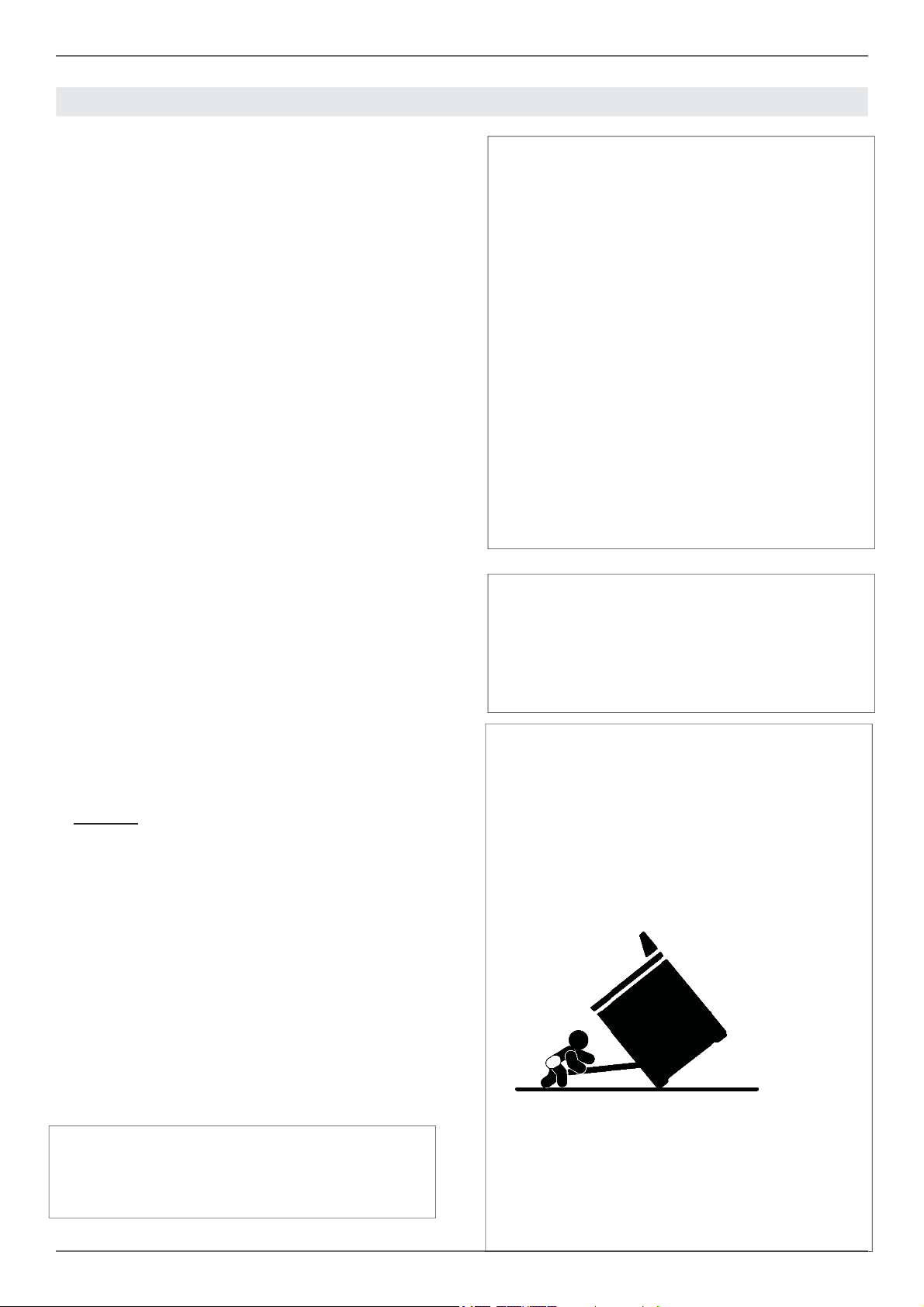
Warning - tipping hazard
A child or adult can tip over the range and be killed.
Install the anti-tip device to the structure and/or
the range. Verify the anti-tip device has been properly installed and engaged.
Page 5

/ Warnings/ Data rating label
Engage the range to the anti-tip device by anti-tip
brackets or anti-tip chain (see installing the anti-tip device chapter). Ensure the anti-tip device is
re-engaged when the range is moved.
Re-engage the anti-tip device if the range is moved. Do not operate the range without te anti-tipdevice in place and engaged.
See anti-tip device installation instructions for
details.
Failure to do so can result in death or serious
burns to children or adults.
DO NOT lift the range by the oven door’s handle,
as this may damage the door hinges and cause
the door to fi t incorrectly.
DO NOT lift the appliance by the range’s control
panel.
The unit is heavy and should be handled accordingly. Proper safety equipment such as gloves
and adequate manpower of at least two people
must be used in moving the range to avoid injury
and to avoid damage to the unit or the fl oor.
Rings, watches, and any other loose items that
may damage the unit or otherwise might become
entangled with the unit should be removed.
Hidden surfaces may have sharp edges. Use caution when reaching behind or under appliance.
DO NOT use a hand truck or appliance dolly on
the back or front of the unit. Handle from the side
only.
DATA RATING LABEL
The data rating label shows the model and serial
number of the range. It is located under the control panel and in the last page of this manual
5
Page 6

/ Before installation
BEFORE INSTALLATION
• This appliance shall only be installed by an au-
thorized professional.
• This appliance shall be installed in accordance
with the manufacturer’s installation instructions.
• This appliance must be installed in accordance
with the norms & standards of the country where it will be installed.
• The installation of this appliance must conform
to local codes and ordinances. In the absence
of local codes, Installations must conforms to
American National Standards, National Fuel
Gas Code ANSI Z223.1 – latest edition/NFPA
54 or B149.1.
• The appliance, when installed, must be electri-
cally grounded in accordance with local codes
or, in the absence of local codes, with the National Electrical Code, ANSI/NFPA 70.
If local codes permit, a fl exible metal appliance
connection conduit with the new AGA or CGA certifi ed design, max. 5 feet (1,5 m) long, ½” I.D. is
recommended for connecting this appliance to the
gas supply line. Do not bend or damage the fl exible connector when moving the appliance.
This appliance must be used with the pressure
regulator provided.
The regulator shall be properly installed in order to
be accessible when the appliance is installed in its
fi nal location. The pressure regulator must be set
for the type of gas to be used. The pressure regulator has ½” female pipe thread. The appropriate
fi tting must be determined based on the size of
your gas supply line, the fl exible metal connector
and the shutoff valve.
The appliance must be isolated from the gas supply piping system by closing its individual manual
shutoff valve during any pressure testing of the
gas supply piping system at test pressures equal
to or less than 1/2 PSI (13,8” iwc or 3,5 kPa).
A manual valve shall be installed in an accessible
location in the gas line external to the appliance
for the purpose of turning on or shutting off gas to
the appliance.
Type of gas
This range can be used with Natural or LP/Propane gas. The range is shipped from the factory
for use with the gas indicated on the rating label
positioned on the lower face of the control panel
and in the last page of this manual. A step by step
conversion procedure is also included in this manual and in each conversion kit.
Gas pressure
The maximum inlet gas supply pressure incoming
to the gas appliance pressure regulator is 1/2 PSI
(13,8’’ iwc or 3,5 kPa). The minimum gas supply
pressure for checking the regulator setting shall
be at least 1“ iwc (249 Pa) above the inlet specifi ed manifold pressure to the appliance; this operating pressure is 4” iwc (1.00 kPa) for Natural
Gas and 10” iwc (2.50 kPa) for LP Gas.
Room ventilation
An exhaust fan may be used with the appliance;
in each case it shall be installed in conformity
with the appropriate national and local standards.
Exhaust hood operation may aff ect other vented
appliances; in each case it shall be installed in
conformity with the appropriate national and local
standards.
Warning
This appliance should not be installed with a
ventilation system that directs air in a downward
direction toward the range. This type of ventilation system may cause ignition and combustion
problems with the appliance resulting in personal
injury, property damage, or unintended operation.
Ventilating systems that direct the air upwards do
not have any restriction.
All opening and holes in the wall and fl oor, back
and under the appliance shall be sealed before
installation of the appliance.
6
Do not use aerosol sprays in the vicinity of
this appliance while it is in operation.
Page 7
VENTILATION PREPARATION
/ Ventilation preparation / Specifi cations
This range will best perform when installed with
Bertazzoni exhaust hoods. These hoods have
been designed to work in conjunction with the
Bertazzoni range and have the same fi nish for a
perfect look.
Before installation of the exhaust hood, consult local or regional building and installation codes for
additional specifi c clearance requirements.
Refer to the range hood installation instructions
provided by the manufacturer for additional information.
Select Hood and Blower Models:
• For wall installations, the hood should be equal
or larger width than the range. Where space
permits, a hood larger than the range may be
desirable for improved ventilation performance.
• For island installations, the hood width should
overhang the range by a minimum of 3” (76
mm) on each side.
Hood Placement:
• For best removal of smoke and odors, the
lower edge of the hood should be installed
between 25 1/2” (65 cm) and 31 1/2” (80 cm)
above the range cooking surface.
• If the hood contains any combustible materials
(i.e. a wood covering), it must be installed at a
minimum of 36” (914 mm) above the cooking
surface.
Consider Make-Up Air:
Due to the high volume of ventilation air, a source of outside replacement air is recommended.
This is particularly important for tightly sealed
and insulated homes. A qualifi ed heating and
ventilating contractor should be consulted.
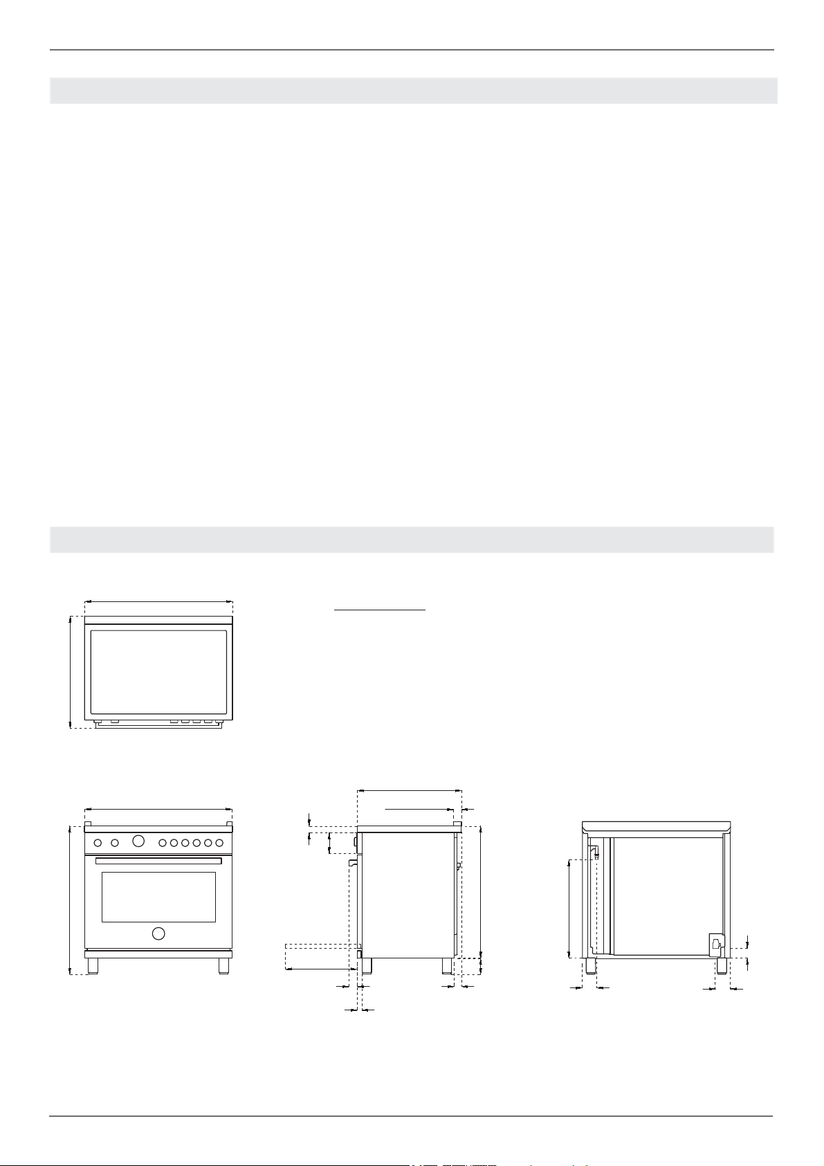
SPECIFICATIONS
A
/8
27''
A
MAX
1/2
37''
30’’ 36’’ 48’’
5/8
1''
5''
A
/16
25''
15/16
1''
32''
7/8
23''
''
/
2''
1/2
- 5''
3/4
5/8
1''
1/8
1''
3''
7/16
3''
3 ''
7/16
2''
11/16
7
Page 8

/ Specifi cations
s
Burner
urner Injector
Injector
diam.[mm]
Auxiliary
0.90
0.54
Semi-rapid
1.18
0.70
Rapid
1.55
0.92
Dual burner
0.80+2.10
0.50+1.20
Gas
as
Type
NG
LP (Propane)
NG
LP (Propane)
NG
LP (Propane)
NG
LP (Propane)
Pressure
Pressure Max Rate Min Rate
[iwc]
4’’
10’’
4’’
10’’
4’’
10’’
4’’
10’’
Max Rate
[Btu/hr]
3,500
3,300
5,900
5,500
10,400
9,500
19000
19000
[W]
1,025
967
1,728
1,611
3,046
2,783
5,567
5,567
Min Rate
[Btu/hr]
900
900
1,500
1,500
2,500
2,500
1,300
1,300
[W]
264
264
439
439
732
732
381
381
By-pass
-pas
diam.[mm]
Regulated
0.29
Regulated
0.36
Regulated
0.47
Regulated
0.34/0.65
See use and care manual for the layout of the surface burners of your range
8
Page 9
CLEARENCES DIMENSIONS
/ Clearence dimensions
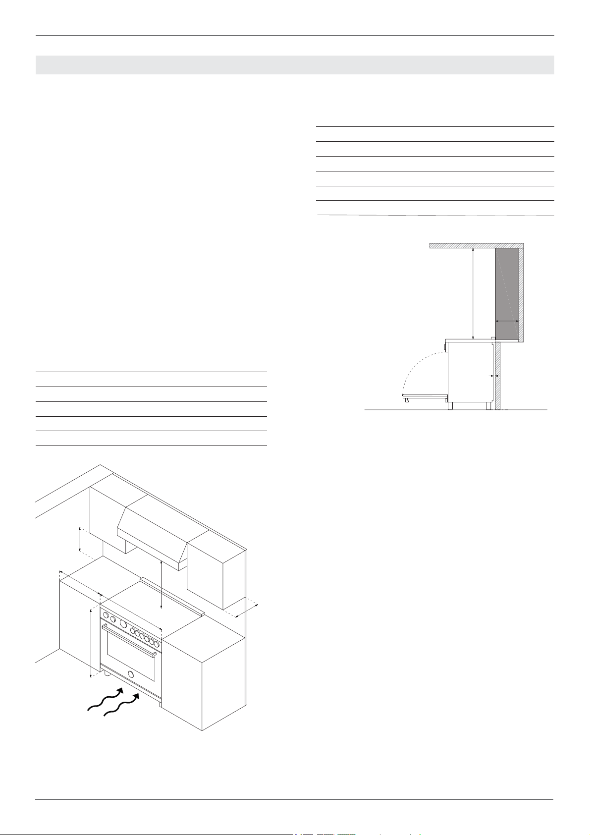
Installation adjacent to kitchen cabinets
This range may be installed directly adjacent to
existing countertop high cabinets (36” or 91.5 cm
from the fl oor).
For the best look, the worktop should be level with
the cabinet countertop. This can be accomplished
by raising the unit using the adjustment spindles
on the legs.
ATTENTION: the range CANNOT be installed directly adjacent to kitchen walls, tall cabinets, tall
appliances, or other vertical surfaces above 36”
(91.4 cm) high. The minimum side clearance in
such cases is 6” (15.2 cm).
Wall cabinets with minimum side clearance must
be installed 18” (45.7 cm) above the countertop
with countertop height between 35 ½” (90.2 cm)
and 37 ¼” (94.6 cm). The maximum depth of wall
cabinets above the range shall be 13” (33.0 cm).
Cabinet
30’’ (76,2 cm)
A
36’’ (91,5 cm) hood with combustible materials
B
13’’ (33,0 cm)
C
18’’ (45,7 cm)
D
35’’ 1/2(90,2 cm) / 37”
E
F
6’ (15,2 cm)
1/4
(94,6 cm)
Metal hood
A
30’’ (76,2 cm)
B
25 1/2’’(65 cm) and 31 1/2’’ (80 cm)
C
13’’ (33,0 cm)
D
18’’ (45,7 cm)
E
35’’ 1/2(90,2 cm) / 37”
F
6’ (15,2 cm)
G
12”(30,50 cm)
H
1” 9/16(4 cm)
1/4
(94,6 cm)
B
G
H
D
F
B
A
C
E
/
If installing toekick, verify that the sum of the cutout areas equal the recommended ventilation (L)
30” area 40 sq. inches ( 25840 mm2)
36” area 51 ½ sq. inches ( 33107 mm2)
48” area 73 ½ sq.inches ( 47547 mm2)
Shaded area behind range indicates minimum
clearance to combustible surfaces, combustible
materials cannot be located within this area.
12” (305 mm) min. to combustible surface with
Flush Island Trim
For Flush Island installations, counter surface
should have a cantilever edge meeting the back
section of the Flush Island Trim accessory.
As defi ned in the “National Fuel Gas Code” (ANSI
Z223.1, Current Edition).
Clearances from non-combustible materials are
not part of the ANSI Z21.1
scope and are not certifi ed by CSA. Clearances of
less than 12” (305 mm)
must be approved by the local codes and/or by
the local authority having jurisdiction.
9
Page 10
/ Installation requirements / Electrical connection
INSTALLATION REQUIREMENTS ELECTRICAL CONNECTION
ELECTRICAL
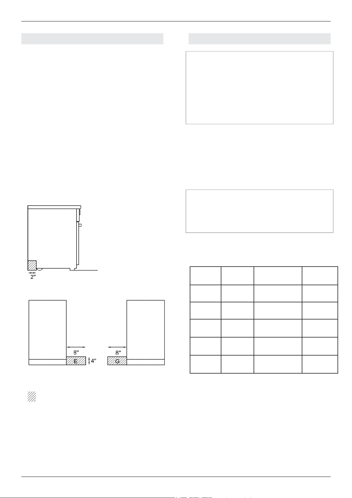
A properly-grounded horizontally- mounted electrical receptacle should be installed no higher than
3” (7.6 cm) above the fl oor, no less than 2” (5 cm)
and no more than 8” (20,3 cm) from the left side
(facing product).
Check all local code requirements.
GAS
An agency-approved, properly-sized manual
shut-off valve should be installed no higher than
3” (7.6 cm) above the fl oor and no less than 2” (5
cm) and no more than 8” (20.3 cm) from the right
side (facing product).
To connect gas between shut-off valve and regulator, use agency-approved, properly sized fl exible
or rigid pipe. Check all local code requirements.
Warning!
ELECTRICAL SHOCK HAZARD
Disconnect electrical power at the circuit breaker box or fuse box before installing the appliance.
Provide appropriate ground for the appliance.
Use copper conductors only.
Failure to follow these instructions could result in serious injury or death.
Warning!
Electrical grounding
This appliance is equipped with a three-prong
plug for your protection against shock hazard and
should be plugged directly into a properly grounded socket. Do not cut or remove the grounding
prong from this plug.
Caution
Label all wires prior to disconnecting when
servicing controls. Wiring errors can cause
improper and dangerous operation.
Verify proper operation after servicing.
installation area for the connection
The appliance shall be connected to a single phase electric line rated at 120/208Vac or 120/240Vac
and 60Hz frequency.
Type Voltage Circuit rating Electrical
supply
30” DFM 120/208V
120/240V
30” DFS 120/208V
120/240V
36” DFM 120/208V
120/240V
36” DFS 120/208V
120/240V
48” DFS 120/208V
120/240V
Install a suitable electric power supply receptacle
connection type NEMA 14-50R able to support a
load of at least 30 A (per line) according to local
code requirements. For four or three wires power
supply connection system see diagram below.
2900W 14A
3700W 16A
4300W 21A
5600W 24A
2900W 14A
3700W 16A
4500W 22,5A
5900W 25,5A
6800W 36,5A
8500W 40,5A
20A
20A
30A
30A
20A
20A
30A
30A
40A
40A
10
Page 11
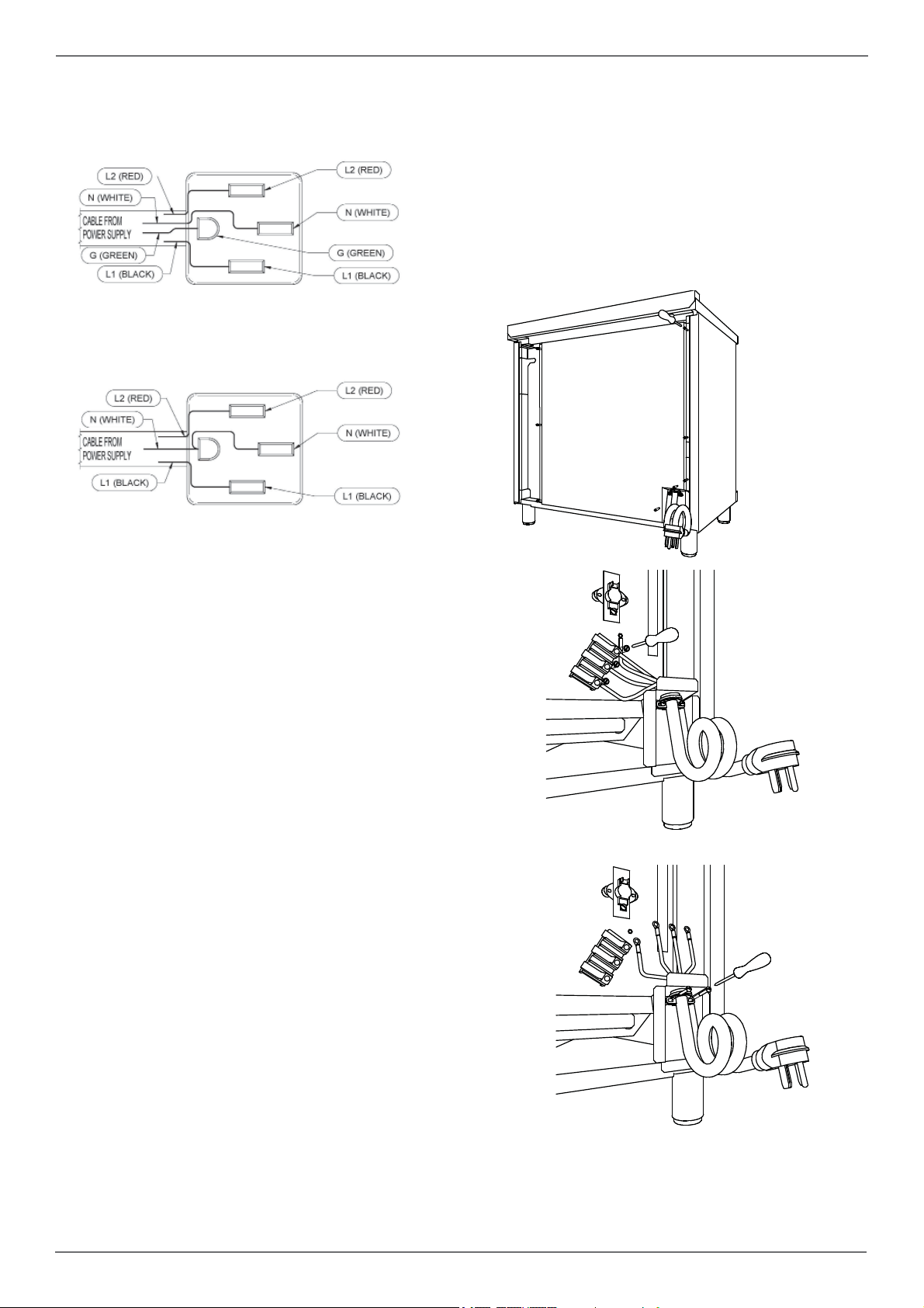
FOUR-WIRE CONN.RECEPTACLE NEMA 14-50R
THREE-WIRE CONN.RECEPTACLE NEMA 14-50R
/ Installation requirements / Electrical connection
The appliance is equipped at the factory with
an electric supply cord set 4 wires type with ring
terminals (L1, L2, N, Ground) suitable for range
use UL/CSA listed type SRDT/DRT 2x6AWG (L1,
L2)+2x8AWG (N, G) rated 300V, 40 or 50A with
fused plug type NEMA 14-50P; cable length 1,5
m.; in case the supply cord set must be replaced,
it shall be replaced with an identical set having the
same technical specs and following carefully the
instructions and diagrams below:
Check your local code for which of the options below should be used in grounding the receptacle
power supply connections.
OPTION 1 – FOUR Wires connection:
-Connect the L1 receptacle terminal to the incoming BLACK electrical supply wire (L1-hot wire)
-Connect the L2 receptacle terminal to the incoming RED electrical supply wire (L2-hot wire)
-Connect the NEUTRAL receptacle terminal to
the incoming NEUTRAL (WHITE) electrical supply wire
-Connect the GROUND receptacle terminal to the
incoming GROUND (GREEN) electrical supply
wire
OPTION 2 - THREE-Wires connection:
-Connect the L1 receptacle terminal to the incoming BLACK electrical supply wire (L1-hot wire)
-Connect the L2 receptacle terminal to the incoming RED electrical supply wire (L2-hot wire)
-Connect the NEUTRAL with the GROUND receptacle terminal to the incoming NEUTRAL (WHITE)
electrical supply wire
DO NOT USE EXTENSION CORDS WITH
THIS APPLIANCE AS IT MAY RESULT IN FIRE,
ELECTRIC SHOCK OR OTHER type of PERSONAL INJURY.
11
Page 12
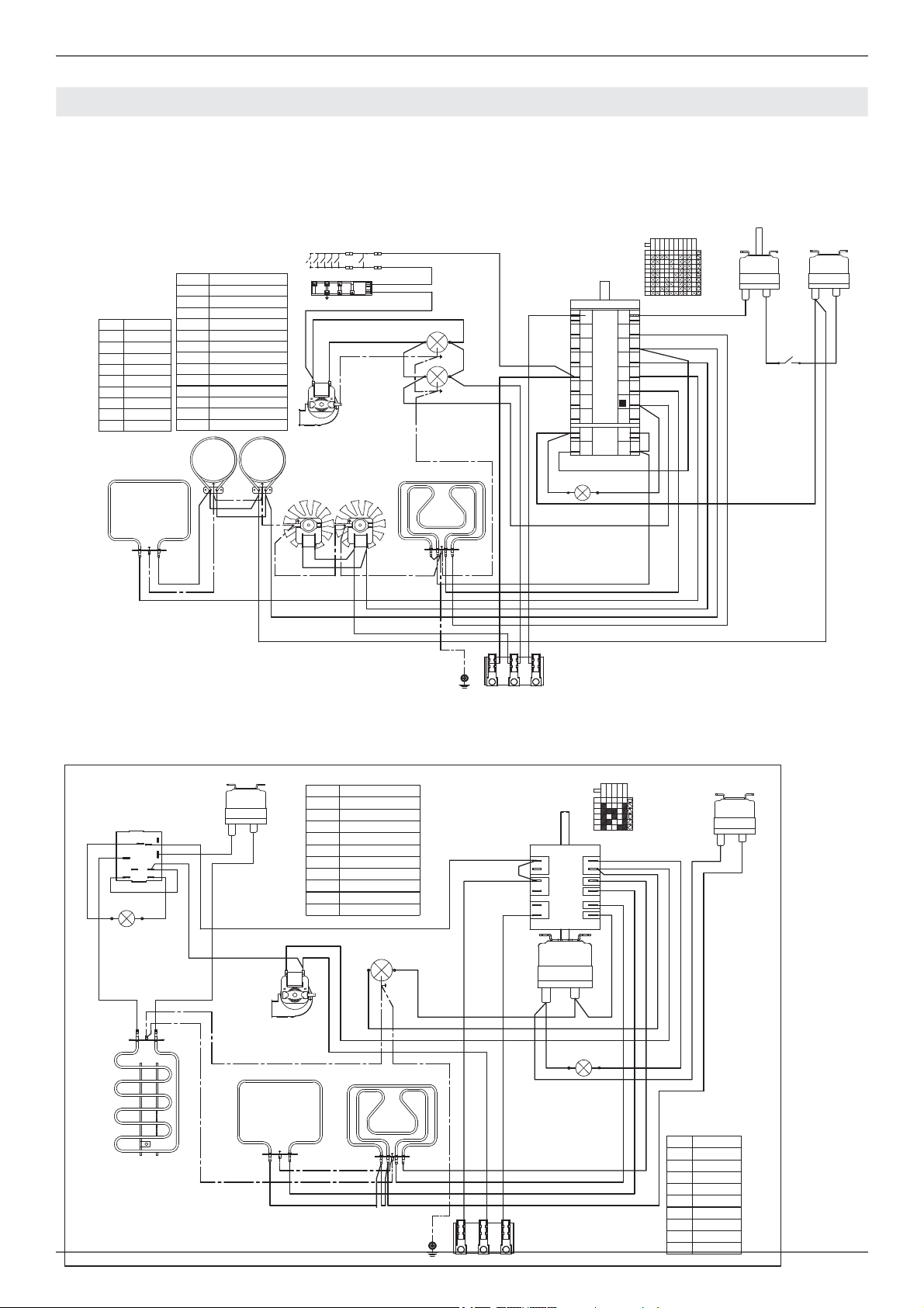
/ Wiring diagram
WIRING DIAGRAM
The electric wiring diagrams and schematics are attached behind the range, and should not be removed
except by a service technician, then replaced after service.
DFM
P2P1P8
P7
P3
P6
P2
P4
P5
P1
0
1
2
3
4
5
6
7
8
9
1
2
3
4
5
6
7
8
1
2
T
a
v
CMV
2
1
TSS
v
a
COLOURS
Simb. D escription
mBrown
rRed
gv G reen
vViolet
gr Grey
a O range
nBlack
bBlue
bi Whit e
RP
LEGENDA
Simb. Description
IGN Ignition Micro switches
COM Oven Function Selec tor
CMV Cooling fan air s ensor switc h
LF Oven lamp
M Terminal Bl ock
MV Fan motor
MVT Cooling fan mot or
RC Round elem ent
RC+RG Upper/gri ll element
RP Lower element
S Signal lights
TSS Safety Thermostat
T Thermost at
bi
a
MVT
RCRC
MV MV
IGN
G
n
bi
a
n
Commutatore.9+0
LF
r
LF
bi
P1
P2
P3
P4
P5
P6
P7
P8
P1
P2
COM
S
b
RG+RC
b
b
v
48 RIGHT SIDE
GE
r
S
m
n
RGR
m
gr
LEGENDA
a
bi
r
bi
L1 N L2
GROUND
n
n
LF
a
a
M
P1-2
P1-1
P1-3
P3-5
P2-4
0
1
2
3
4
COM
5
P3
5
2
P1
1
3
r
P2
g
4
a
b
b
a
a
bi
v
2
1
TSS
b
T
S
b
b
a
b
Simb. Description
C+T Swit ch + thermost at
GE Griddle Thermostat
2
1
TSS
bi
bi
LF Oven lamp
MTerminal Block
MVT Cooling fan motor
RC+RG Upper/grill element
RGR Griddle Element
RP Lower element
S Signal lights
TSS Safety Thermos tat
bi
MVT
12
RG+RC
RP
L1 N L2
GROUND
M
COLOURS
Simb. Description
mBrown
rRed
gv Green
vViolet
gr G rey
aOrange
nBlack
bBlue
bi White
Page 13
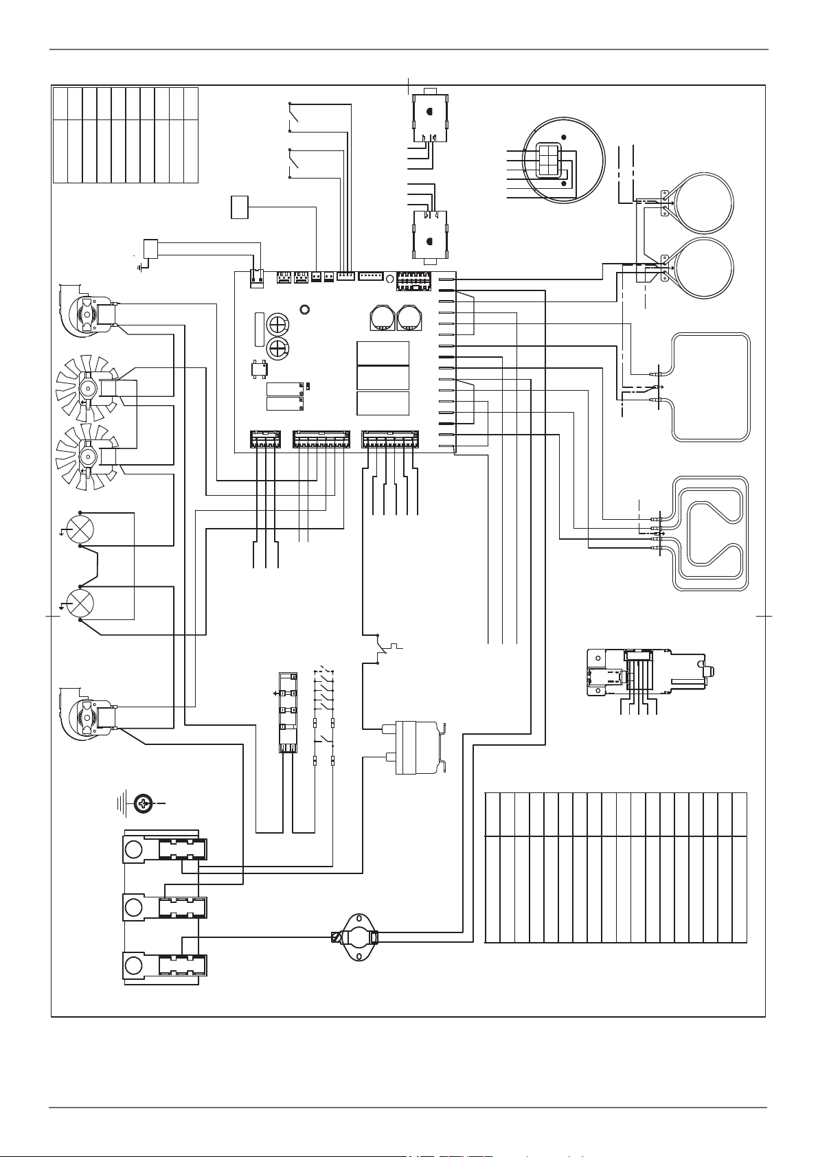
30 /36 /48 DFS
nBlack
aOrange
gr Grey
vViolet
bi Whi te
bBlue
/ Wiring diagram
Simb. Description
mBrown
gv Green
rRed
COLOURS
down
CMV
TS
to MV
to MV
MVMV
LF
up
PT
up
CMV
to CN23 - 3
to CN23 - 2
to CN23 - 1
to CN23 - 3
to CN23 - 2
to CN23 - 1
to CN1 - 1
to CN1 - 2
to CN1 - 3
to CN1 - 4
to CN1 - 5
to CN1 - 6
EG
FS
A
MT
MVT
B
b
n
bi
a
CN30
1.3
CN23
1.3
CN24
CN21
1..4
CN2
CN1- 1....6
a
RCRC
to MV
v
r
b
v
RP
b
CN22 -3.1
CN27 - 6.....1
CN28 - 6.....1
gr
gr
to M-GROUND
to MV
bi
to M-L1
to M-L1
to DL
to DL
to M-N
RG+RC
a
to DL
to DL
LF
MVT
down
GROUND
M
L1 N L2
bi
to RP
to M-L1
to M-N
to GROUND
n
K
n
G
IGN
bi
1
bi
2
n
n
n
n
to M-L1
to M-L1
to M-L1
DL
to CN26 - 3
to CN27 - 6
to CN26 - 2
to CN27 - 5
to M-L1
r
r
TSS
RC+RG Upper/gri ll elem ent
bi
n
MVT Cool ing fan motor
MV Fan motor
RC Round element
PT Oven sensor Temp. (PT1000)
MT Meat Probe
LF Oven lamp
MTerminal Block
IGN Ignit ion Micro switches
TS Oven Temperature Selecton
K Termal cut out
EG Electronic Gauge
DL Door Lo ck - Door Switc h
FS Oven Function Selector
G S park Generat or
Simb. Description
CMV Cooling fan air sensor switch
B Thermal cut-out
LEGENDA
n
r
B
13
Page 14
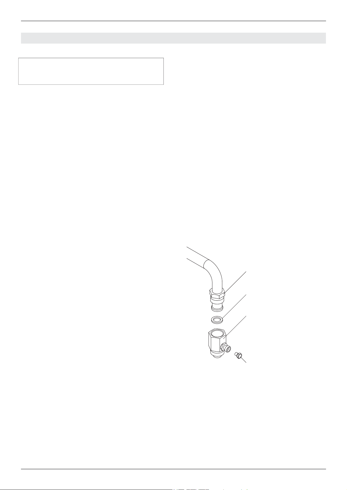
/ Gas connection
GAS CONNECTION
Warning!
DO NOT USE AN OPEN FLAME WHEN
CHECKING FOR LEAKS!
Leak testing of the appliance shall be conducted
according to the manufacturer’s instructions. Before placing the oven into operation, always check
for leaks with soapy water solution or other acceptable method.
Check for gas leakage with soapy water solution or
other acceptable methods in all gas connections
installed between inlet gas pipe of the appliance,
gas regulator, till to the manual shut-off valve.
All gas connections must comply with national and
local codes. The gas supply line (service) must be
the same size or greater than the inlet line of the
appliance. This range uses a 1/2” NPT inlet (see
drawing below for details of gas connection). On
all pipe joints use appropriate sealant resistant to
gas to joint the adapter to range manifold use only
the blue gasket supplied.
If necessary, the appliance must be converted by
the dealer, by a factory-trained professional or by
a qualifi ed licensed plumber or gas service company.
FLEXIBLE CONNECTIONS
In case of installation with fl exible couplings and/
or quick-disconnect fi ttings, the installer must use
a heavy-duty, AGA design-certifi ed commercial
fl exible connector of at least 1/2” (1.3 cm) ID NPT
(with suitable strain reliefs) in compliance with
ANSI Z21.41 and Z21.69 standards.
In Massachusetts: The unit must be installed
with a 36” (3-foot) long fl exible gas connector.
In Canada: use CAN 1-6.10-88 metal connec-
tors for gas appliances and CAN 1-6.9 M79 quick
disconnect device for use with gas fuel.
PRESSURE TEST-POINT STOPPER
VALVE
To avoid gas leaks, the pressure test-point stopper valve and gasket supplied with the range must
be installed on the gas fi tting at the back of the
range according to the diagram below.
Gas conversion is important for safe and eff ective use of the appliance. It is the responsibility of
the dealer and the owner of the range to perform
the appropriate gas conversion following the directions of the manufacturer.
THE GAS CONVERSION PROCEDURE IS
DESCRIBED IN THIS MANUAL AND IN THE
PACKAGE CONTAINING THE CONVERSION
NOZZLES SHIPPED WITH EVERY RANGE.
Please provide the service person with this manual before work is started on the range.
MANUAL SHUT-OFF VALVE
THIS VALVE IS NOT SHIPPED WITH THE APPLIANC AND MUST BE SUPPLIED BY THE INSTALLER.
The manual shut-off valve must be installed in the
gas service line between the gas hook-up on the
wall and the appliance inlet, in a position where it
can be reached quickly in the event of an emergency.
GAS PIPE
GASKET
GAS CONNECTION ADAPTOR
1/2’’NPT WITH PRESSURE TEST
POINT 1/8’’ NPT (TO BE FIXED
TOWARD EXTERNAL SIDE OF
THE APPLIANCE)
PRESSURE TEST-POINT
STOPPER
In Massachusetts: A ‘T’ handle type manual
gas valve must be installed in the gas supply line
to this appliance.
14
Page 15

PRESSURE REGULATOR
Since service pressure may fl uctuate with local
demand, every gas cooking appliance must be
equipped with a pressure regulator on the incoming service line for safe and effi cient operation.
The pressure regulator shipped with the appliance has two female threads ½” NPT. The regulator
shall be installed properly in order to be accessible
when the appliance is installed in its fi nal position.
/ Gas connection
Manifold pressure should be checked with a manometer and comply with the values indicated below:
Natural gas 4.0” iwc.
LP/Propane 10.0” iwc.
Incoming line pressure upstream from the regulator must be 1” iwc. higher than the manifold pressure in order to check the regulator.
The regulator used on this range can withstand a
maximum input pressure of 1/2 PSI (13,8” w.c. or
3,5 kPa) If the line pressure exceeds that amount,
a stepdown regulator is required.
The appliance, its individual shut-off valve, and
the pressure regulator must be disconnected from
the gas line during any pressure testing of that system at pressures in excess of 1/2 PSI (13,8” iwc
or 3,5 kPa).
The individuaL manual shut-off valve must be in
the OFF position during any pressure testing of
the gas supply piping system at test pressures
equal to or less than 1/2 PSI (13,8” iwc or 3,5 kPa).
Warning
Before carrying out any servicing operation disconnect the appliance from gas and electric
supply and extra appliance from fi nal installation
place in order to have access to the appliance for
proper servicing intervention.
15
Page 16

/ Installation
INSTALLATION
APPLIANCE INSTALLATION
Unpacking the range
• Remove all packing materials from the ship-
ping pallet but leave the adhesive-backed foam
layer over brushed-metal surfaces to protect it
from scratches until the range is installed in its
fi nalposition. Only the fi lm on the side panels
should be removed before inserting the range
between the cabinets.
• Examine the appliance after unpacking it. In the
event of transport damage, do not plug it. Take
pictures of the damage and report it immediately to the freight forwarder.
• Remove the oven door(s). This will reduce the
weight of the range.
• The grates, griddle plate, burner caps, and oven
racks should be removed to facilitate handling.
• Before moving the range, protect the fl oor to
prevent damage.
REMOVING THE OVEN DOOR
Prepare the door for removal. Flip up the locking
clamps on each door hinge. Slowly shut the door
until the protruding clamps stop the movement.
Pull oven door upwards and remove.
Do not lift or carry the oven door by its handle!
This may damage the hinges.
1
2
16
3
Page 17

/ Installation
INSTALLING THE LEGS
Bertazzoni ranges must be used only with the legs
properly installed.
Four height-adjustable legs are supplied with the
range in the polysterene container situated over
the appliance.
Before installing the legs, position the appliance
near its fi nal location as the legs are not suitable
for moving the appliance over long distances.
After unpacking the range, raise it enough to insert the legs in the appropriate receptacles situated on the lower part of the appliance. Lower the
range gently to keep any undue strain from legs
and mounting hardware. If possible use a pallet or
lift jack instead of tilting the unit.
Adjust leg height to the desired level by twisting
the inside portion of the leg assembly until the proper height is reached. Check with a level that the
cooktop is perfectly level.
INSTALLING THE WORKTOP
FRONTGUARD
To increase the clearance between the front edge
of the worktop and the burners it is possible to
install the worktop frontguard shipped with the appliance.
To install the front guard,
• Locate the two fi xing holes on the end of the
frontguard
• Locate the two fi xing holes in the bottom side of
the worktop
• Fix the frontguard with the 2 supplied screw
1
2
3
4
17
Page 18

/ Installation
INSTALLING THE ISLAND TRIM
The island trim must be installed prior to operation
of the appliance for appropriate ventilation of the
oven compartment.
The island trim is only placed on the cooktop, remove all tape and packaging before installing it.
INSTALLING BACKGUARD (OPTIONAL)
The backguard must be installed prior to operation of the appliance for appropriate ventilation of
the oven compartment.
The backguard is an optional contact you dealer
for buying it.
1 1
2 2
3
3
4 4
18
Page 19

INSTALLING THE ANTI/TIP DEVICES
/ Installing the anti/tip devices
ANTI-TIP BRACKETS
The anti-tip bracket shipped with the range must
be properly secured to the rear wall as shown in
the picture below.
The height of the bracket from the fl oor must be
determined after the range legs have been adjusted to the desired height and after the range has
been levelled.
• Measure the distance from the fl oor to the
bottom of the anti-tip bracket receptacle on the
back of the appliance.
• Position the anti-tip brackets on the wall at
the desired height plus 1/8” (0.32 cm). The
brackets must be placed at 2”5/16 (6,0 cm)
from the side of the range.
• Secure the brackets to the wall with appropria-
te hardware.
• Slide the range against the wall until the
brackets are fully inserted into their receptacles on the back of the range.
ANTI/TILT CHAIN
The anti-tilt chain shall be installed on right or left
side alternatively according below instructions.
The chain shall be hand pulled and fi xed to open
hook through closed ring.
Disengage the chain prior to moving the appliance
for service.
Attention:
Once servicing operation have been completed
the anti-tilt devices ( brackets and chain) shall be
re-engaged according above instruction/installations.
1
CLOSED RING OPEN HOCK
2
19
Page 20

/ Gas conversion
GAS CONVERSION
Warning!
Before carrying out this operation, disconnect the
appliance from gas and electricity.
Gas conversion shall be conducted by a factory-trained professional.
Call the customer service hotline to identify a fac-
tory-trained professional near your home.
The gas conversion procedure for this range includes 6 steps:
• Pressure regulator
• Surface burners
• Oven burner
• Broiler burner
• Visual checks prior to closure of oven bottom
panel
• Adjustment of minimum setting
LP
The conversion is not completed if all 6 steps have
not been concluded properly.
Before performing the gas conversion, locate the
package containing the replacement nozzle shipped with every range.
IMPORTANT: Each nozzle has a number indicating its fl ow diameter printed on the body. Consult
the table number 1 for matching nozzles to burners.
Save the nozzles removed from the range for future use.
Step 1: pressure regulator
The pressure regulator supplied with the appliance is a convertible type pressure regulator for use
with Natural Gas at a nominal outlet pressure of
4” w.c. or LP gas at a nominal outlet pressure of
11” w.c. and it is pre-arranged from the factory to
operate with one of these gas/pressure as indicated in the labels affi xed on the appliance, package
and Instruction booklet.
To convert the regulator for use with the other gas:
Unscrew by hand the upper cap of the regulator, remove the white plastic attachment from the
cap, reverse its direction and screw it again fi rmly against the cap. The white plastic attachment
has arrows indicating the position for natural gas
(NAT) and LP gas (LP).
Screw by hand the metal cap in the original position on the regulator.
NAT
Step 2: surface burners
To replace the nozzles of the surface burners, lift
up the burners and unscrew the nozzles shipped
with the range using a 7 mm (sochet wrench).
Replace nozzles using the conversion set supplied with the range or by a Bertazzoni authorized parts warehouse. Each nozzle has a number
indicating its fl ow diameter printed on the body.
Consult the table number 1 and matching nozzles
to burners.
20
Page 21

Step 3: visual checks
Surface burners
The burner fl ame color should be blue with no yellow on the tips. It is not uncommon to see orange
in the
fl ame color; this indicates the burning of airborne
impurities in the gas and will disappear with use.
With propane (LP) gas, slight yellow tips on the
primary icone are normal.
The fl ame should burn completely around the burner cap. If it doesn’t, check that the cap is positioned
correctly on the base and that the ports are not
blocked.
The fl ame should be stable with no excessive noise or fl uttering.
/ Gas conversion
Step 4: minimum fl ame adjustment
WARNING!
These adjustments should be made only for use
of the appliance with natural gas. For use with liquid propane gas, the choke screw must be fully
turned in a clockwise direction.
SURFACE BURNERS
Light one burner at a time and set the knob to the
MINIMUM position (small fl ame).
Remove the knob.
The range is equipped with a safety valve. Using
a small-size slotted screwdriver, locate the choke
valve on the valve body and turn the choke screw
to the right or left until the burner fl ame is adjusted
to desired minimum.
Make sure that the fl ame does not go out when
switching quickly from the MAXIMUM to the MINIMUM position.
For the gas valve of dual burner the choke valve
is located on the valve body (fi g.20), the A screw
adjust the outer ring, the B screw adjust the inner
ring.
yellow fl ames:
further adjustment is required
yellow tips on outer cones:
normal for LP gas
soft blue fl ames:
normal for natural gas
After performing all these visual checks, reinstall
the bottom panel of the oven compartment and
proceed to setting the minimum for each burner.
B
A
21
Page 22

/ Installation checklist / fi nal preparation
INSTALLATION CHECKLIST FINAL PREPARATION
A qualifi ed installer should carry out the following
checks:
Range mounted on its legs
Island trim or Backguard attached according to instruction
Anti-tip device properly installed
Clearance to cabinet surfaces as manufacturer’s guideline
Proper ground connection
Gas service line connected following manufacturer’s guideline
Valves, stoppers and gasket installed
between the range and the service line
Gas connection tested and free of gas
leaks
Range settled for the type of gas available
in the household
Each burner lights satisfactorily, both individually and with other burners operating
Flame appear sharp blue, with no yellow
tipping, shooting or fl ame lifting
Minimum settled for all burners
Oven light works properly
• Before using the oven, remove any protective
wrap from the stainless steel.
• All stainless steel body parts should be wiped
with hot, soapy water and with a liquid stainless
steel cleanser.
• If buildup occurs, do not use steel wool, abrasi-
ve cloths, cleaners, or powders!
• If it is necessary to scrape stainless steel to re-
move encrusted materials, soak with hot, wet
cloths to loosen the material, then use a wood
or nylon scraper.
• Do not use a metal knife, spatula, or any other
metal tool to scrape stainless steel! Scratches
are almost impossible to remove.
• Before using the oven for food preparation,
wash the cavity thoroughly with a warm soap
and water solution to remove fi lm residues and
any dust or debris from installation, then rinse
and wiped dry.
Attention!
When using the oven for the fi rst time it
should be operated for 15-30 minutes at a temperature of about 500°F/260°C (main oven) or
440°F/227°C(auxiliary oven) without cooking
anything inside in order to eliminate any moisture and odours from the internal insulation.
22
Page 23

BERTAZZONI SERVICE
Bertazzoni is committed to providing the best customer and product service. We have a dedicated
team of trained professionals to answer your needs.
If you own a Bertazzoni appliance and need service in the US or Canada please use the following
contact information:
e-mail: aftersaleservice@bertazzoni.com
Telephone - Monday through Friday,
7.30am to 7.30pm EST (except US public holidays).
US 866-905-0010
WESTERN CANADA 866-905-0010 (BC,AB,SK,MB)
EASTERN CANADA 800-561-7265 (ON,QC,NL,NB,NS,PE)
/ Bertazzoni service
23
Page 24

BERTAZZONI
MANUEL D'INSTALLATION
CUISINIÈRES À GAZ/ELECTRIQUE AUTONOMES
3100299
WWW.BERTAZZONI.COM
1
Page 25

/ Table des matières
TABLE DES MATIÈRES
AVERTISSEMENTS ____________________________________________________________
ÉTIQUETTE SIGNALÉTIQUE _____________________________________________________
AVANT L'INSTALLATION ________________________________________________________
PRÉPARATION DE LA VENTILATION ______________________________________________
SPÉCIFICATIONS ______________________________________________________________
ESPACE DE DÉGAGEMENT ______________________________________________________
CONDITIONS D'INSTALLATION _________________________________________________
Électricité __________________________________________________________________
Gaz ________________________________________________________________________
RACCORDEMENT ÉLECTRIQUE _________________________________________________
SCHÉMA DE CÂBLAGE ________________________________________________________
RACCORDEMENT AU GAZ ______________________________________________________
Vanne de fermeture manuelle __________________________________________________
Tuyaux fl exibles _____________________________________________________________
Soupape d'arrêt au point consigne de pression ___________________________________
Régulateur de pression _______________________________________________________
INSTALLATION ________________________________________________________________
Déballage de la cuisinière _____________________________________________________
Retrait de la porte du four _____________________________________________________
Installation des pieds _________________________________________________________
Installation de la protection frontale de la surface de cuisson ________________________
Installation de la garniture ____________________________________________________
Installation de la protection arrière (en option) ____________________________________
INSTALLATION DES DISPOSITIFS ANTI-BASCULEMENT _____________________________
Supports anti-basculement ____________________________________________________
Chaîne anti-basculement _____________________________________________________
CONVERSION À UN AUTRE TYPE DE GAZ __________________________________________
LISTE DE CONTRÔLE POUR L'INSTALLATION ______________________________________
PRÉPARATION FINALE __________________________________________________________
ASSISTANCE BERTAZZONI ______________________________________________________
4
5
6
7
7
9
10
10
10
10
12
14
14
14
14
15
16
16
16
17
17
18
18
19
19
19
20
22
22
23
2
Page 26

/ Modèles
Modèles
MAST305DFMBIE
MAST305DFMNEE
MAST305DFMXE
MAST365DFMBIE
MAST365DFMNEE
MAST365DFMXE
MAST366DFSXT
MAST486GDFSXT
Modèles
PROF304DFSART
PROF304DFSBIT
PROF304DFSGIT
PROF304DFSNET
PROF304DFSROT
PROF304DFSXT
PROF366DFSART
PROF366DFSBIT
PROF366DFSGIT
PROF366DFSNET
PROF366DFSROT
PROF366DFSXT
PROF486GDFSART
PROF486GDFSBIT
PROF486GDFSGIT
PROF486GDFSNET
PROF486GDFSROT
PROF486GDFSXT
3
Page 27

/ Avertissements
AVERTISSEMENTS
Pour un fonctionnement correct et en toute sécurité,
l'appareil doit être correctement installé et mis à la
terre par un technicien qualifi é. NE PAS tenter de
régler, réparer, réviser ou remplacer un composant
de l'appareil à moins que le présent manuel ne
le recommande spécifi quement. Toute autre
intervention doit être réalisée par un opérateur
qualifi é. L'installateur montrera l'emplacement de la
vanne de fermeture du gaz et les modalités d'arrêt en
cas d'urgence. Un technicien certifi é devra intervenir
pour tout réglage ou conversion aux gaz naturel ou
LPG.
POUR L'INSTALLATEUR : Avant d'installer l'appareil
Bertazzoni, veuillez lire attentivement ces instructions.
Cet appareil doit être installé conformément aux
instructions d'installation du fabricant.
IMPORTANT: ces instructions doivent être laissées
à la disposition du propriétaire, qui les conservera
pour toute consultation future ou en cas de visite
d'un inspecteur. NE PAS retirer les étiquettes, les
avertissements ou les plaques permanentes apposés
sur le produit. Cela risquerait d'annuler la garantie.
AVERTISSEMENT !
Si les informations dans ce manuel ne sont
pas suivies scrupuleusement, un incendie
ou une explosion risque(nt) de survenir et
d’entraîner des dommages matériels, blessures
personnelles ou la mort.
- Ne pas stocker ni utiliser de l’essence ou autres
substances infl ammables à proximité de cet appareil
ou d’autres appareils électroménagers.
- QUE FAIRE SI VOUS SENTEZ LE GAZ
• N’allumer aucun appareil électroménager.
• Ne toucher aucun interrupteur électrique.
• N’utiliser aucun téléphone dans votre immeuble.
• Appeler immédiatement votre fournisseur de gaz
depuis un téléphone voisin. Suivre les instructions du
fournisseur de gaz.
• Si vous ne pouvez pas joindre vos fournisseurs
de gaz, appelez le service incendie.
-L’installation et la maintenance doivent être
entreprises par un installateur qualifi é, agence de
service ou fournisseur de gaz.
L'installation doit être conforme aux règlementations
locales. En l'absence de règlementations :
• États-Unis : l'installation doit être conforme à la
règlementation nationale relative au gaz (National
Fuel Gas Code) ANSI Z223.1 INFPA54.
• Massachusetts : Tout appareil au gaz doit être
installé par un plombier ou un installateur de gaz
agréé par l'état. Une vanne manuelle à poignée
de type « T » doit être installée sur la conduite
d'alimentation en gaz de l'appareil.
• Canada : L'installation doit être réalisée
conformément aux règlementations en matière
d'installation au gaz CAN/CGA B149.1 et CAN/
CGA B149.2 et/ou aux règlementations locales.
L'installation électrique doit être conforme à la
règlementation canadienne en matière d'électricité
CSA C22.1, Partie 1, et/ou aux règlementations
locales.
La cuisinière N'A PAS été conçue pour être installée
dans des maisons préfabriquées (mobiles) ou des
caravanes.
NE PAS installer la cuisinière en extérieur.
DANGER ! RISQUE DE DÉCHARGE ÉLECTRIQUE !
Pour éviter les risques de décharge électrique, de
lésion ou de blessure mortelle, vérifi er que l'appareil
a été correctement mis à la terre, conformément aux
règlementations locales ou, en leur absence, à la
règlementation américaine en matière d'électricité
(NEC). ANSI/NFPA 70 – dernière édition.
DANGER ! RISQUE DE FUITE DE GAZ !
Pour éviter les risques de blessure ou d'accidents
mortels, la détection des fuites sur l'appareil doit
être conforme aux instructions du fabricant. Avant
d'utiliser l'appareil, toujours contrôler l'absence de
fuites à l'aide d'une solution d'eau savonneuse.
NE PAS UTILISER DE FLAMME LIBRE POUR
RECHERCHER LES FUITES DE GAZ.
L'appareil doit être correctement raccordé à la terre. Le
raccordement à la terre réduit le risque de décharge
électrique en fournissant un passage sécurisé au
courant électrique en cas de court-circuit.
Avertissement !
Pour éviter les risques de lésion, de blessure mortelle
ou de dommages aux biens, suivre scrupuleusement
les informations contenues dans ce manuel visant à
prévenir les incendies ou les explosions.
4
Avertissement – risque de basculement
Les enfants et les adultes peuvent faire basculer
la cuisinière si celle-ci n'a pas été fi xée au mur, ce
qui pourrait entraîner des blessures mortelles. Pour
réduire le risque de basculement de l'appareil, celui-ci
doit être fi xé au moyen de dispositifs anti-basculement,
conformément aux instructions d'installation.
Page 28

/ Avertissements/ Étiquette signalétique
E
Remettre en place les dispositifs anti-basculement après tout déplacement de la cuisinière. Ne
pas utiliser la cuisinière si les dispositifs anti-basculement ne sont pas en place et enclenchés.
Ne pas utiliser la cuisinière si les dispositifs
anti-basculement n'ont pas été correctement
installés et enclenchés. Pour plus d'informations,
consulter les instructions d'installation.
Le non-respect des instructions d'installation peut occasionner des blessures
graves, voire mortelles, aux enfants et
aux adultes.
Ne PAS soulever la cuisinière par les poignées du
four, car cela pourrait endommager les charnières
de porte et entraîner une fermeture incorrecte de
la porte.
Ne PAS soulever la cuisinière en la saisissant par
le panneau de commande.
La cuisinière est lourde et doit être manipulée avec
les soins nécessaires. Pour tout déplacement
de la cuisinière, prévoir la présence d’au moins
deux personnes dotées d’équipements adaptés,
notamment des gants, afi n d’éviter de se blesser
ou d’endommager la cuisinière ou le sol.
Les bagues, montres et tout accessoire ample
susceptible d’endommager la cuisinière ou de se
coincer dans la cuisinière doivent être retirés.
Les surfaces cachées peuvent avoir des bords
tranchants. Faire très attention en cas de contact
avec l’arrière ou le dessous de la cuisinière.
Ne PAS positionner de diable ou de chariot sur
l’avant ou l’arrière de la cuisinière. Le positionner
sur le côté uniquement.
ÉTIQUETTE SIGNALÉTIQUE
TIQUETTE SIGNALÉTIQU
L’étiquette signalétique indique le modèle et le
numéro de série de la cuisinière. Elle se trouve
sous le panneau de commande et à la dernière
page de ce manuel.
5
Page 29

/ Avant l'installation
AVANT L'INSTALLATION
• L'appareil doit être installé uniquement par un
professionnel autorisé.
• Cet appareil doit être installé conformément
aux instructions d'installation du fabricant.
• L'appareil doit être installé conformément
aux normes et aux règlementations du pays
d'installation.
• L'installation de cet appareil doit être conforme
aux règlementations locales. En l'absence de
règlementations locales, l'installation doit être
conforme aux normes américaines du National
Fuel Gas Code ANSI Z223.1 – dernière édition/
NFPA 54 ou B149.1.
• Une fois installé, l'appareil doit être raccordé
à la terre conformément aux règlementations
locales ou, en leur absence, à la règlementation
américaine en matière d'électricité (NEC),
ANSI/NFPA 70.
Si les règlementations locales l'autorisent, un
raccord métallique fl exible de nouvelle conception
homologué conformément aux normes AGA ou
CGA, de 5 pieds (1,5 m) max. de longueur, ½”
de diamètre interne (I.D.), est recommandé pour
raccorder l'appareil à la conduite d'alimentation
en gaz. Veiller à ne pas plier ou endommager le
raccord fl exible lors du déplacement de l'appareil.
L'appareil doit être utilisé avec le régulateur
de pression fourni.
Le régulateur doit être correctement installé afi n
d'être accessible une fois l'appareil installé dans
son emplacement fi nal. Le régulateur de pression
doit être réglé conformément au type de gaz
utilisé. Le régulateur de pression dispose d'un
fi letage interne femelle ½”. Une fi xation adaptée
doit être déterminée en fonction des dimensions
de la conduite d'alimentation en gaz, du raccord
métallique fl exible et de la vanne de fermeture.
L'appareil doit être isolé du système d'alimentation
en gaz en fermant la vanne manuelle individuelle
lors de chaque test de pression du système
d'alimentation en gaz à des pressions de test
inférieures ou égales à 1/2 psi (13,8 inH2O ou 3,5
kPa).
d'alimentation en gaz, indépendante de l'appareil,
afi n d'ouvrir ou de fermer l'alimentation en gaz.
Type de gaz
Cette cuisinière peut fonctionner avec du gaz
naturel ou du gaz propane/LPG. Cette cuisinière
est expédiée de l'usine pour être utilisée avec le
gaz indiqué sur l'étiquette signalétique se trouvant
sur la face inférieure du panneau de commande et
à la dernière page de ce manuel. Une procédure
de conversion pas à pas est également comprise
dans ce manuel et dans tout kit de conversion.
Pression du gaz
La pression d'alimentation en gaz maximale pour
le régulateur de pression de la cuisinière à gaz est
de 1/2 psi (13,8 inH2O ou 3,5 kPa). La pression
d'alimentation en gaz minimale pour vérifi er le
réglage du régulateur doit être d'au moins 1 inH2O
(249 Pa) au-dessus de la pression d'alimentation
spécifi ée pour le collecteur. Cette pression de
fonctionnement est de 4 inH2O (1,00 kPa) pour
le gaz naturel et de 10 inH2O (2,50 kPa) pour le
gaz LPG.
Avertissement
Ventilation de la pièce
Il convient d'associer un ventilateur extracteur à
l'appareil. Celui-ci doit être installé conformément
aux normes locales et nationales en vigueur. Le
fonctionnement d'une hotte aspirante peut avoir
une incidence sur d'autres appareils de ventilation.
Elle doit être installée conformément aux normes
locales et nationales en vigueur.
Avertissement
Cet appareil ne doit pas être installé avec un
système de ventilation qui dirige l'air vers le bas,
en direction de la cuisinière. Ce type de système
de ventilation peut entraîner des incendies
et des problèmes de combustion, avec pour
conséquences des blessures, des dommages aux
biens et un fonctionnement non maîtrisé. Il n'existe
pas de restrictions concernant les systèmes de
ventilation qui dirigent l'air vers le haut.
Ne pas utiliser de sprays aérosols à proximité
de l'appareil en fonctionnement.
Toutes les ouvertures et les trous dans le mur et le
plancher, derrière et sous l'appareil, doivent être
scellés avant l'installation de celui-ci.
Une vanne manuelle doit être installée dans
un emplacement accessible sur la conduite
6
Page 30

PRÉPARATION DE LA VENTILATION
/ Préparation de la ventilation / Spécifi cations
Cette cuisinière a un fonctionnement optimal
en cas d'installation avec une hotte d'extraction
Bertazzoni. Ces hottes, conçues pour être
associées à la gamme Bertazzoni, off rent un
aspect impeccable grâce à leur fi nition identique.
Avant d'installer la hotte d'extraction, consulter les
règlementations locales ou régionales en matière
de construction et d'installation pour connaître les
critères spécifi ques aux espaces de dégagement.
Pour plus d'informations, se reporter aux
instructions d'installation de la hotte fournies par
le fabricant.
Choisir les modèles de hotte et de ventilateur :
• En cas d'installation murale, la hotte doit
présenter une largeur au moins égale à celle de
la cuisinière. Lorsque l'espace le permet, il peut
être souhaitable d'installer une hotte plus large
que la cuisinière, pour une meilleure ventilation.
• En cas d'installations autonomes, la largeur de
la hotte doit dépasser celle de la cuisinière d'au
moins 3” (76 mm) de chaque côté.
Positionnement de la hotte :
• Pour une meilleure extraction des fumées et
des odeurs, le bord inférieur de la hotte doit
se trouver entre 25 1/2” (65 cm) et 31 1/2”
(80 cm) au-dessus de la surface de cuisson de
la cuisinière.
• Si la hotte contient des matériaux
combustibles (par ex. parement en bois), elle
doit être installée à au moins 36” (914 mm) audessus de la surface de cuisson.
Air d'appoint :
En présence d'un volume élevé d'air de
ventilation, il est recommandé de disposer d'une
source d'air de remplacement extérieur. Cela est
particulièrement important pour les habitations
fermées hermétiquement et fortement isolées.
Consulter une entreprise de chauff age et de
ventilation qualifi ée.
SPÉCIFICATIONS
A
/8
27''
A
MAX
1/2
37''
5/8
1''
''
5''
/
30’’ 36’’ 48’’
2''
1/8
1''
1''
25''
A
15/16
/16
32''
7/8
23''
1/2
- 5''
3/4
5/8
1''
3''
7/16
3''
3 ''
7/16
2''
11/16
7
Page 31

/ Spécifi cations
n
Brûleur
rûleur Injecteur
Auxiliaire
Semi-rapide
Rapide
Double brûleur
Injecteur
diam. [mm]
0.90
0.54
1.18
0.70
1.55
0.92
0.80+2.10
0.50+1.20
Gaz
az
Type
Gaz naturel
LPG (propane)
Gaz naturel
LPG (propane)
Gaz naturel
LPG (propane)
Gaz naturel
LPG (propane)
Pression
Pression Valeur maximale
[inH2O]
4’’
10’’
4’’
10’’
4’’
10’’
4’’
10’’
Valeur maximale
[Btu/hr]
3,500
3,300
5,900
5,500
10,400
9,500
19,000
19,000
[W]
1,025
967
1,729
1,611
3,047
2,783
5,567
5,567
Valeur minimale
aleur minimale
[Btu/hr]
900
900
1,500
1,500
2,500
2,500
1,300
1,300
[W]
264
264
439
439
732
732
381
381
Dérivation
érivatio
diam. [mm]
Régulé
0.29
Régulé
0.36
Régulé
0.47
Régulé
0.34/0.65
Consulter le manuel d'utilisation et d'entretien pour connaître la confi guration des brûleurs
de votre cuisinière.
8
Page 32

ESPACE DE DÉGAGEMENT
/ Espace de dégagement
Installation adjacente à des meubles de cuisine
Cette cuisinière peut être installée à proximité
directe de plans de travail avec meubles intégrés
(36” ou 91,5 cm par rapport au sol).
Pour un aspect optimal, la surface de la cuisinière
doit être au même niveau que celle du plan de
travail avec meuble intégré. Pour ce faire, régler la
hauteur de l'appareil en agissant sur les dispositifs
de réglage des pieds.
ATTENTION : la cuisinière NE DOIT PAS être
installée à proximité directe des murs de la cuisine,
de meubles ou d'appareils hauts, ou d'autres
surfaces verticales de plus de 36” (91,4 cm) de
hauteur. Dans ces cas, l'espace latéral doit être
d'au moins 6” (15,2 cm).
Les meubles muraux présentant cet espace latéral
minimum doivent être installés à 18” (45,7 cm) audessus du plan de travail, avec une hauteur de
plan de travail comprise entre 35 ½” (90,2 cm)
et 37 ¼” (94,6 cm). La profondeur maximale des
meubles muraux au-dessus de la cuisinière doit
être de 13” (33 cm).
Hotte métallique
A
30’’ (76,2 cm)
B
25 1/2’’(65 cm) et 31 1/2’’ (80 cm)
C
13’’ (33,0 cm)
D
18’’ (45,7 cm)
E
35’’ 1/2(90,2 cm) / 37”
F
6” (15,2 cm)
G
12”(30,50 cm)
H
1” 9/16(4 cm)
1/4
(94,6 cm)
B
G
Meuble de cuisine
30’’ (76,2 cm)
A
36’’ (91,5 cm) hotte avec matériaux combustibles
B
13’’ (33,0 cm)
C
18’’ (45,7 cm)
D
A
1/4
(94,6 cm)
B
C
35’’ 1/2(90,2 cm) / 37”
E
F
6’ (15,2 cm)
D
F
E
/
En cas d’installation de toekick, vérifi ez que la
somme des zones de découpe correspond à la
ventilation recommandée (L)
30” surface 40 sq. inches ( 25840 mm2)
36” surface 51 ½ sq. inches ( 33107 mm2)
48” surface 73 ½ sq.inches ( 47547 mm2)
H
La zone grisée derrière la cuisinière indique
l'espace minimum à respecter par rapport à la
surface de cuisson. Aucun matériau combustible
ne doit se trouver dans cette zone.
12” (305 mm) min. par rapport aux surfaces
combustibles avec garniture affl eurante.
Pour des installations autonomes, la surface de
travail doit être dotée d'un bord saillant faisant la
jonction avec la partie arrière de la garniture.
Comme indiqué dans la règlementation américaine
en matière de gaz ANSI Z223.1 (édition actuelle).
Le dégagement par rapport aux matériaux non
combustibles ne rentre pas dans le cadre de la
norme ANSI Z21.1
et n'est pas certifi é par l'Association canadienne
de normalisation (CSA). Les dégagements de
moins de 12” (305 mm)
doivent être conformes aux règlementations
locales et/ou être approuvés par l'autorité locale
compétente.
9
Page 33

/ Conditions d'installation / Raccordement électrique
CONDITIONS D'INSTALLATION RACCORDEMENT ÉLECTRIQUE
ÉLECTRICITÉ
Une prise électrique montée horizontalement et
correctement mise à la terre doit être installée à
une hauteur maximale de 3” (7,6 cm) et minimale
de 2” (5 cm) par rapport au sol, et à une distance
maximale de 8” (20,3 cm) par rapport au côté
gauche du produit (en lui faisant face).
Vérifi er les dispositions des règlementations
locales.
GAZ
Une vanne de fermeture manuelle correctement
dimensionnée et approuvée par un organisme
agréé doit être installée à une hauteur maximale
de 3” (7,6 cm) et minimale de 2” (5 cm) par rapport
au sol, et à une distance maximale de 8” (20,3 cm)
par rapport au côté droit du produit (en lui faisant
face).
Pour réaliser le raccordement en gaz entre la
vanne de fermeture et le régulateur, utiliser un
fl exible de dimensions adaptées ou un tuyau
rigide approuvé par un organisme agréé. Vérifi er
les dispositions des règlementations locales.
DANGER !
RISQUE DE DÉCHARGE ÉLECTRIQUE !
Couper l'alimentation électrique au niveau
du disjoncteur ou du tableau à fusibles avant
d'installer l'appareil.
L'appareil doit être correctement mis à la terre.
Utiliser uniquement des conducteurs en
cuivre.
Le non-respect de ces instructions pourrait
entraîner de graves blessures, voire la mort.
DANGER !
Mise à la terre
L'appareil est équipé d'une prise à trois broches
qui garantit une protection contre les décharges
électriques. Elle doit être branchée directement à
une prise murale correctement mise à la terre. Ne
pas couper ou retirer la broche de terre de cette
prise.
Attention
Étiqueter chaque câble avant de les débrancher
pour eff ectuer des contrôles d'entretien.
Des erreurs de câblage peuvent entraîner un
fonctionnement incorrect et dangereux.
Vérifi er le bon fonctionnement de la cuisinière
après l'entretien.
zone réservée au branchement
L’appareil sera branché à un système électrique
monophasé à 120/208 Vca ou 120/240 Vca,
fréquence de 60 Hz.
Type Vca évaluation Fournit.
électrique
30” DFM 120/208V
30” DFS 120/208V
36” DFM 120/208V
36” DFS 120/208V
48” DFS 120/208V
Brancher un réceptacle d’alimentation électrique
adapté à l’aide d’une prise type NEMA 14-50R,
capable de supporter une charge d’au moins
30 A (par ligne), conformément aux exigences
applicables des codes locaux (système de
connexion d’alimentation à trois ou quatre fi ls) ;
voir schémas.
120/240V
120/240V
120/240V
120/240V
120/240V
2900W 14A
3700W 16A
4300W 21A
5600W 24A
2900W 14A
3700W 16A
4500W 22,5A
5900W 25,5A
6800W 36,5A
8500W 40,5A
20A
20A
30A
30A
20A
20A
30A
30A
40A
40A
10
Page 34

RECEPTACLE DE CONNEXION A QUATRE
FILS (NEMA 14-50R)
RECEPTABLE DE CONNEXION A TROIS FILS
(NEMA 14-50R)
/ Conditions d'installation / Raccordement électrique
NE PAS UTILISER DE RALLONGE AVEC CET
APPAREIL. LE FAIRE PEUT ENTRAINER UN
INCENDIE, UN CHOC ELECTRIQUE OU AUTRE
DOMMAGE CORPOREL.
L’appareil est fourni avec un cordon d’alimentation
à 4 fi ls avec des bornes à anneau (L1, L2, N,
Terre), adapté pour des usages conformes aux
normes UL/CSA indiquées (type SRDT/DRT 2 x
6 AWG (L1, L2) + 2 x 8 AWG (N, Terre)), d’une
puissance nominale de 300 V , 40 ou 50 A avec
une prise enfi chable type NEMA 14-50P ; câble
de 1,5 m de long ; si le cordon d’alimentation doit
être remplacé, il le sera par un cordon identique
qui aura les mêmes caractéristiques techniques
et en suivant scrupuleusement les instructions (et
schémas) ci-dessous :
Vérifi er les exigences applicables des codes
locaux de votre pays, pour voir laquelle des
options ci-dessous devra être utilisée pour relier
les connexions d’alimentation du réceptacle à la
terre :
OPTION 1 – Connexion à QUATRE fi ls :
- Connecter la borne L1 du réceptacle au câble
d’alimentation électrique entrant NOIR (L1-fi l
chaud)
- Connecter la borne L2 du réceptacle au câble
d’alimentation électrique entrant ROUGE (L2-fi l
chaud)
- Connecter la borne NEUTRE du réceptacle au
câble d’alimentation électrique entrant NEUTRE
(BLANC)
- Connecter la borne de TERRE du réceptacle au
câble d’alimentation électrique de TERRE (VERT)
OPTION 2 – Connexion à TROIS fi ls :
- Connecter la borne L1 du réceptacle au câble
d’alimentation électrique entrant NOIR (L1-fi l
chaud)
- Connecter la borne L2 du réceptacle au câble
d’alimentation électrique entrant ROUGE (L2-fi l
chaud)
- Connecter la borne NEUTRE et la borne de
TERRE du réceptacle au câble d’alimentation
électrique entrant NEUTRE (BLANC)
11
Page 35

/ Schéma de câblage
SCHÉMA DE CÂBLAGE
Les schémas de câblage électrique fi gurent à l'arrière de la cuisinière et ne peuvent être retirés que par un
technicien de maintenance, qui doit les remettre en place une fois l'entretien réalisé.
30 /36 DFM
P2P1P8
P7
P3
P6
P2
P4
P5
P1
0
1
2
3
4
5
6
7
8
9
1
2
3
4
5
6
7
8
1
2
T
a
v
CMV
2
1
TSS
v
a
COLOURS
Simb. Descr iption
mBrown
rRed
gv Green
vViolet
gr Grey
a Orange
nBlack
bBlue
bi Whi te
RP
LEGENDA
Simb. Description
IGN Ignition Mic ro switches
COM Oven Function S elector
CMV Cooling fan air sensor swit ch
LF Oven lamp
M Terminal B lock
MV Fan motor
MVT Cooling fan m otor
RC Round el ement
RC+RG Upper/ grill element
RP Lower element
S Signal light s
TSS Safet y Thermostat
T Thermos tat
bi
a
MVT
RCRC
MV MV
IGN
G
n
n
r
Commutatore.9+0
P1
P2
P3
P4
P5
P6
P7
P8
P1
P2
bi
LF
LF
a
bi
COM
S
b
RG+RC
b
b
v
48 PART DROITE
GE
r
S
m
n
RGR
m
bi
gr
a
b
2
1
TSS
bi
bi
MVT
r
bi
LEGENDA
Simb. Description
C+T Switch + thermos tat
GE Griddle Thermostat
LF Oven lamp
M Terminal Block
MVT Cooling fan motor
RC+RG Upper/grill element
RGR Griddle E lement
RP Lower element
S Signal lights
TSS S afety Thermost at
a
a
bi
b
L1 N L2
GROUND
LF
M
P1-2
P1-1
P1-3
P3-5
P2-4
0
1
2
3
4
COM
n
n
r
5
P3
5
2
P1
1
3
P2
g
4
a
b
b
a
a
bi
v
2
1
TSS
b
T
a
S
b
12
RG+RC
RP
L1 N L2
GROUND
M
COLOURS
Simb. Description
mBrown
rRed
gv Green
vViolet
gr Grey
aOrange
nBlack
bBlue
bi W hite
Page 36

30 /36 /48 DFS
nBlack
aOrange
gr Grey
vViolet
bi W hite
bBlue
/ Schéma de câblage
Simb. Description
mBrown
gv G re en
rRed
COLOURS
down
CMV
TS
to MV
to MV
MVMV
LF
PT
up
CMV
to CN23 - 3
to CN23 - 2
to CN23 - 1
to CN23 - 3
to CN23 - 2
to CN23 - 1
to CN1 - 1
to CN1 - 2
to CN1 - 3
to CN1 - 4
to CN1 - 5
to CN1 - 6
EG
FS
A
MT
MVT
up
B
b
n
bi
a
a
RCRC
to MV
1.3
CN24
CN21
1..4
CN2
CN1- 1....6
CN30
1.3
CN23
v
r
b
v
RP
b
CN22 -3.1
CN27 - 6.....1
CN28 - 6.....1
gr
gr
to M-GROUND
to MV
bi
to M-L1
to M-L1
to DL
to DL
to M-N
RG+RC
a
to DL
to DL
LF
MVT
down
GROUND
M
L1 N L2
bi
to RP
to M-L1
to M-N
to GROUND
n
K
n
G
IGN
bi
1
bi
2
n
n
n
n
to M-L1
to M-L1
to M-L1
DL
to CN26 - 3
to CN27 - 6
to CN26 - 2
to CN27 - 5
r
r
to M-L1
TSS
RC+RG Upper/gril l elemen t
bi
n
MVT Cooling fan mot or
MV Fan motor
RC Round el ement
PT Oven sensor Temp. (PT1000)
MT Meat Probe
LF Oven lamp
M Termi nal Block
IGN Igniti on Micro s witches
TS Oven Temperature Selecton
K Termal cut out
EG Electronic Gauge
FS Oven Function Selector
G Spark Generat or
Simb. Description
CMV Cooling fan air sensor switch
DL Door Loc k - Door Switch
B Thermal c ut-out
LEGENDA
n
r
B
13
Page 37

/ Raccordement au gaz
RACCORDEMENT AU GAZ
Avertissement !
NE PAS UTILISER DE FLAMME LIBRE POUR
RECHERCHER LES FUITES DE GAZ !
La recherche de fuites sur la cuisinière doit
être réalisée conformément aux instructions du
fabricant. Avant d'utiliser le four, toujours réaliser
une recherche de fuites avec une solution d'eau
savonneuse ou toute autre méthode valide.
Vérifi er l'absence de fuites de gaz en utilisant de
l'eau savonneuse ou en ayant recours à d'autres
méthodes valides pour tous les raccords de gaz
installés entre la conduite d'alimentation en gaz
de l'appareil, le régulateur de gaz et la vanne de
fermeture manuelle.
Tous les raccordements au gaz doivent être
conformes aux règlementations locales et
nationales. La conduite d'alimentation en gaz doit
être de dimensions au moins égales à celles du
tuyau d'entrée de l'appareil. Cette cuisinière utilise
un adaptateur NPT 1/2” (voir le dessin ci-après
pour des informations sur le raccordement au
gaz). Pour toutes les jonctions de tuyaux, utiliser
un joint adapté résistant au gaz ; pour joindre
l'adaptateur et le collecteur de la cuisinière, utiliser
uniquement le joint bleu fourni.
Le cas échéant, la conversion de l'appareil doit
être réalisée par le revendeur, un professionnel
formé par le fabricant, un plombier ou une
entreprise spécialisée, qualifi és et agréés.
Massachusetts : Une vanne manuelle de gaz
à poignée de type « T » doit être installée sur la
conduite d'alimentation en gaz de l'appareil.
TUYAUX FLEXIBLES
En cas d'installation avec des tuyaux fl exibles
et/ou à déconnexion rapide, l'installateur doit
utiliser un connecteur fl exible résistant, certifi é
AGA pour une utilisation commerciale, d'au moins
1/2” (1,3 cm) de diamètre interne (I.D.) NPT
(enfi chables) conforme aux normes ANSI Z21.41
et Z21.69.
Massachusetts : Installer la cuisinière avec un
raccord de gaz fl exible d'une longueur de 36” (3
pieds).
Canada : Utiliser des connecteurs métalliques
CAN 1-6.10-88 pour cuisinière à gaz et un
dispositif à déconnexion rapide CAN 1-6.9 M79
en cas d'utilisation avec du gaz.
SOUPAPE D'ARRÊT AU POINT CONSIGNE
DE PRESSION
Pour éviter les fuites de gaz, la soupape d'arrêt au
point consigne de pression et le joint fourni avec
la cuisinière doivent être installés sur le raccord
de gaz à l'arrière de la cuisinière, conformément
au schéma ci-après.
La conversion est importante pour une utilisation
effi cace et sûre de l'appareil. Il incombe au
revendeur et au propriétaire de la cuisinière
de réaliser une conversion au gaz adaptée et
conforme aux instructions du fabricant.
LA PROCÉDURE DE CONVERSION EST
DÉCRITE DANS CE MANUEL ET DANS LE
SACHET CONTENANT LES DIFFÉRENTS
INJECTEURS FOURNI AVEC LA CUISINIÈRE.
Ce manuel doit être fourni à la personne en
charge de l'entretien avant toute intervention sur
la cuisinière.
VANNE DE FERMETURE MANUELLE
CETTEVANNE N'EST PAS EXPÉDIÉE AVEC
LA CUISINIÈRE ET DOIT ÊTRE FOURNIE PAR
L'INSTALLATEUR.
La vanne de fermeture manuelle doit être installée
sur la conduite d'alimentation en gaz, entre le
branchement mural et l'entrée de l'appareil,
dans une position rapidement accessible en cas
d'urgence.
CONDUITE DE GAZ
JOINT
CONNECTEUR DE GAZ 1/2’’NPT
AVEC POINT CONSIGNE
DE PRESSION 1/8’’ NPT (À
FIXER VERS L'EXTÉRIEUR DE
L'APPAREIL)
SOUPAPE D'ARRÊT AU POINT
CONSIGNE DE PRESSION
14
Page 38

RÉGULATEUR DE PRESSION
Dans la mesure où la pression de service peut
fl uctuer en fonction de la demande locale, chaque
appareil de cuisson au gaz doit être équipé
d'un régulateur de pression sur la conduite
d'alimentation, pour garantir un fonctionnement
sûr et effi cace.
Le régulateur de pression fourni avec l'appareil
dispose de deux fi letages femelles ½” NPT. Le
régulateur doit être correctement installé afi n
d'être accessible une fois l'appareil installé dans
son emplacement fi nal.
/ Raccordement au gaz
La pression dans le collecteur doit être contrôlée
au moyen d'un manomètre et être conforme aux
valeurs indiquées ci-après :
Gaz naturel 4,0” inH2O
LPG/Propane 10,0” inH2O
La pression de la conduite d'alimentation en
amont du régulateur doit être supérieure de 1”
inH2O à celle dans le collecteur afi n de pouvoir
contrôler le régulateur.
Le régulateur utilisé avec la cuisinière est adapté
à une pression d'alimentation maximale de 1/2
psi (13,8” inH2O ou 3,5 kPa). Si la pression
d'alimentation dépasse cette valeur, un hacheur
série est nécessaire.
L'appareil, sa vanne de fermeture individuelle et
le régulateur de pression doivent être débranchés
de la conduite de gaz en cas de contrôle de
pression du circuit à des pressions supérieures à
1/2 psi (13,8” inH2O ou 3,5 kPa).
La vanne manuelle de fermeture doit être
FERMÉE lors de chaque test de pression du
circuit d'alimentation en gaz à des pressions de
test inférieures ou égales à 1/2 psi (13,8” inH2O
ou 3,5 kPa).
Avertissement
Avant toute opération d'entretien, débrancher la
cuisinière des sources d'alimentation en gaz et
en électricité, et débrancher tout autre appareil
de la zone d'installation fi nale afi n d'avoir accès
à la cuisinière et de pouvoir réaliser correctement
l'opération d'entretien.
15
Page 39

/ Installation
INSTALLATION
INSTALLATION DE L'APPAREIL
Déballage de la cuisinière
• Retirer tous les matériaux d'emballage de la
paletted'expédition sans toucher à la mousse
postérieure adhésive sur les surfaces en métal
brossé, afi n de protéger la cuisinière des rayures
jusqu'à son installation à son emplacement fi nal.
Ne retirer que le fi lm protégeant les panneaux
latéraux avant de positionner la cuisinière entre
les meubles de cuisine.
• Examiner la cuisinière après l'avoir déballée. En
cas de dommage résultant du transport, ne pas
la brancher. Prendre des photos du dommage
et en informer immédiatement le transporteur.
• Retirer la ou les portes du four. Cela réduira le
poids de la cuisinière.
• Retirer les grilles, plaques et chapeaux des
brûleurs pour faciliter le déplacement de la
cuisinière.
• Avant de la déplacer, protéger le sol pour éviter
tout dommage.
RETRAIT DE LA PORTE DU FOUR
Préparer la porte en vue de son retrait. Rabattre
les fi xations sur chaque charnière de porte.
Fermer lentement la porte jusqu'à ce que la
fi xation saillante ne bloque le mouvement.
Tirer la porte vers le haut et la retirer.
Ne pas soulever ou tirer la porte par sa poignée !
Cela pourrait endommager les charnières.
1
2
16
3
Page 40

/ Installation
INSTALLATION DES PIEDS
Les cuisinièresBertazzoni ne doivent être utilisées
qu'une fois leurs pieds correctement installés.
Quatre pieds réglables en hauteur sont fournis avec
la cuisinière dans le conteneur en polystyrène placé
sur le dessus de l'appareil.
Avant d'installer les pieds, positionner la cuisinière
à proximité de son emplacement fi nal ; les pieds
ne doivent pas être utilisés pour la déplacer sur de
longues distances.
Après avoir déballé la cuisinière, la soulever
suffi samment afi n de pouvoir insérer les pieds dans
les logements correspondants situés sous l'appareil.
Abaisser lentement la cuisinière pour éviter toute
sollicitation excessive sur les pieds et le matériel de
montage. Si possible, utiliser une palette ou un cric
plutôt que de faire basculer la cuisinière.
Régler la hauteur des pieds au niveau souhaité en
tournant la partie interne du pied. À l'aide d'un niveau,
vérifi er que la surface de cuisson est parfaitement
plane.
INSTALLATION DE LA PROTECTION
FRONTALE DE LA SURFACE DE CUISSON
Afi n d'augmenter l'espace entre le bord frontal
de la surface de cuisson et les brûleurs, il est
possible d'installer la protection frontale fournie
avec la cuisinière.
Pour installer la protection frontale :
• Repérer les deux trous de fi xation aux extrémités
de la protection frontale.
• Repérer les deux trous de fi xation sous le
rebord de la surface de cuisson.
• Fixer la protection frontale avec les 2 vis
fournies.
1
2
3
4
17
Page 41

/ Installation
INSTALLATION DE LA GARNITURE
La garniture doit être installée avant toute
utilisation de la cuisinière afi n de garantir la
ventilation appropriée du compartiment du four.
La garniture est uniquement positionnée sur la
surface de cuisson. Retirer tous les rubans et
matériaux d'emballage avant son installation.
Avant l’installation, portez des gants de sécurité.
INSTALLATION DE LA PROTECTION
ARRIÈRE (EN OPTION)
La protection arrière doit être installée avant
toute utilisation de la cuisinière afi n de garantir la
ventilation appropriée du compartiment du four.
La protection arrière est un équipement en option.
Contactez votre revendeur pour vous la procurer.
Avant l’installation, portez des gants de sécurité.
1 1
2 2
3
3
4 4
18
Page 42

/ Installation des dispositifs anti-basculement
INSTALLATION DES DISPOSITIFS ANTI-BASCULEMENT
SUPPORTS ANTI-BASCULEMENT
Les supports anti-basculement fournis avec la
cuisinière doivent être correctement fi xés au
mur postérieur, comme indiqué sur la fi gure cidessous.
La hauteur correcte des supports est déterminée
après avoir réglé les pieds de la cuisinière et une
fois celle-ci nivelée.
• Mesurer la distance entre le sol et le bas
du logement du support anti-basculement à
l'arrière de la cuisinière.
• Positionner les supports anti-basculement
sur le mur à la hauteur souhaitée plus
1/8” (0,32 cm). Les supports doivent être
positionnés à 2”5/16 (6,0 cm) par rapport au
côté de la cuisinière.
• Fixer les supports au mur à l'aide d'outils
adaptés.
• Faire glisser la cuisinière contre le mur jusqu'à
ce que les supports soient complètement insérés
dans leurs logements à l'arrière de la cuisinière.
CHAÎNE ANTI-BASCULEMENT
La chaîne anti-basculement doit être fi xée au côté
gauche ou droit, selon les instructions ci-après.
Tirer la chaîne manuellement à travers l'anneau et
l'insérer dans le crochet.
Défaire la chaîne avant tout déplacement de la
cuisinière en vue d'une opération d'entretien.
Attention :
Une fois les opérations d'entretien terminées, les
dispositifs anti-basculement (supports et chaîne)
doivent être remis en place conformément aux
instructions ci-dessus.
1
ANNEAU CROCHET
2
19
Page 43

/ Conversion à un autre type de gaz
CONVERSION À UN AUTRE TYPE DE GAZ
Avertissement !
Avant de réaliser cette opération, débrancher
l'appareil de l'alimentation en gaz et en électricité.
La conversion doit être eff ectuée par un
professionnel formé à cet eff et par le fabricant.
Appeler le service clients pour trouver le
professionnel formé par le fabricant le plus proche.
Pour cette cuisinière, la procédure de conversion
à un autre type de gaz comprend 6 étapes :
• Régulateur de pression
• Brûleurs de la surface de cuisson
• Brûleur du four
• Brûleur du grill
• Contrôles visuels avant la fermeture du panneau
arrière du four
• Réglage du minimum
LPG
La conversion n'est pas terminée tant que ces 6
étapes n'ont pas été correctement réalisées.
Avant de réaliser la conversion à un autre type
de gaz, trouver le sachet contenant l'injecteur de
remplacement fourni avec la cuisinière.
IMPORTANT : Sur chaque injecteur se trouve un
numéro correspondant à son débit. Consulter le
tableau n° 1 pour connaître la correspondance
entre les injecteurs et les brûleurs.
Conserver les injecteurs retirés de la cuisinière
pour toute utilisation future.
Étape 1 : régulateur de pression
Le régulateur de pression fourni avec la cuisinière
est de type convertible, adapté à une utilisation
avec du gaz naturel à une pression nominale de
sortie de 4” inH2O ou avec du gaz LPG à une
pression nominale de sortie de 11” inH2O. Il a
été réglé en usine pour fonctionner avec l'un de
ces gaz ou pressions, comme indiqué sur les
étiquettes apposées sur la cuisinière, l'emballage
et dans le livret d'instructions.
Convertir le régulateur pour l'utiliser avec un autre
gaz :
dévisser à la main le couvercle supérieur du
régulateur, retirer l'attache en plastique blanc
du couvercle, inverser son sens et le revisser
fermement contre le couvercle. L'attache en
plastique blanc comporte des fl èches indiquant la
position du gaz naturel (NAT) et du gaz LPG (PL).
Visser à la main le couvercle métallique dans sa
position d'origine sur le régulateur.
NAT
Étape 2 : brûleurs de la surface de cuisson
Pour remplacer les injecteurs des brûleurs de
la surface de cuisson, soulever les brûleurs et
dévisser les injecteurs fournis avec la cuisinière
au moyen d'une clé de 7 mm (à douille).
Remplacer les injecteurs en utilisant le kit de
conversion fourni avec la cuisinière ou par un
magasin de pièces détachées Bertazzoni agréé.
Sur chaque injecteur se trouve un numéro
correspondant à son débit. Consulter le tableau
n° 1 pour connaître la correspondance entre les
injecteurs et les brûleurs.
20
Page 44

Étape 3 : contrôles visuels
Brûleurs de la surface de cuisson
La fl amme du brûleur doit être bleue, sans
coloration jaune aux extrémités. Il n'est pas rare
de voir de l'orange sur la
fl amme. Cela indique la combustion d'impuretés
en suspension dans le gaz et disparaîtra pendant
l'utilisation. Avec du gaz propane (LPG), il est
normal de voir de petites pointes jaunes sur les
premières fl ammes.
La combustion de la fl amme doit être complète
autour du chapeau du brûleur. Dans le cas
contraire, vérifi er que le chapeau est correctement
positionné sur son support et que les orifi ces ne
sont pas obstrués.
La fl amme doit être stable, sans bruit ni oscillation
excessive.
/ Conversion à un autre type de gaz
Étape 4 : réglage du minimum
AVERTISSEMENT !
Ces réglages doivent uniquement être réalisés
en vue d'une utilisation de la cuisinière avec
du gaz naturel. En cas d'utilisation avec du gaz
propane liquide, la vis d'étranglement doit être
complètement tournée dans le sens horaire.
BRÛLEURS DE LA SURFACE DE CUISSON
Allumer un brûleur à la fois et positionner le bouton
sur la position MINIMUM (petite fl amme).
Retirer le bouton.
La cuisinière est équipée d'une soupape de sécurité.
Au moyen d'un tournevis plat de petites dimensions,
repérer la soupape d'étranglement sur le corps de
la soupape et tourner la vis d'étranglement vers la
droite ou la gauche jusqu'à ce que la fl amme du
brûleur atteigne le minimum souhaité.
S'assurer que la fl amme ne s'éteint pas lors du
passage rapide de la position MAXIMUM à la
position MINIMUM.
Pour la vanne de gaz du double brûleur, la
soupape d’étranglement est située sur le corps
de la vanne (fi g. 20) ; la vis A permet de régler
l’anneau extérieur et la vis B l’anneau intérieur.
fl ammes jaunes :
la fl amme doit à nouveau être
réglée
pointes jaunes aux extrémités :
normal pour le gaz LPG
fl ammes bleu clair :
normal pour le gaz naturel
Une fois tous les contrôles visuels eff ectués,
réinstaller le panneau arrière du compartiment
du four et procéder au réglage du minimum de
chaque brûleur.
B
A
21
Page 45

/ Liste de contrôle pour l'installation / Préparation fi nale
LISTE DE CONTRÔLE POUR L'INSTALLATION PRÉPARATION FINALE
Un installateur qualifi é devra réaliser les contrôles
suivants :
La cuisinière est-elle installée sur ses pieds ?
La garniture ou la protection arrière est-elle
fi xée conformément aux instructions fournies ?
Les dispositifs anti-basculement sont-ils
correctement installés ?
Le dégagement par rapport aux surfaces
des meubles est-il conforme aux consignes
du fabricant ?
Le raccordement à la terre a-t-il été
correctement réalisé ?
La conduite d'alimentation en gaz est-elle
conforme aux consignes du fabricant ?
Les vannes, les soupapes d'arrêt et le joint
ont-ils été installés entre la cuisinière et la
conduite d'alimentation ?
Le branchement de gaz a-t-il été testé et
est-il exempt de fuites ?
La cuisinière est-elle adaptée au type de
gaz disponible dans l'habitation ?
Chaque brûleur fonctionne-t-il de manière
satisfaisante, à la fois séparément et en
même temps que les autres brûleurs ?
La fl amme est-elle bleue, sans pointes
jaunes, crépitements ou remontées de
fl amme ?
Le minimum a-t-il été réglé pour tous les
brûleurs ?
La lumière du four fonctionne-t-elle
correctement ?
• Avant d'utiliser le four, retirer tout fi lm protecteur
éventuellement présent sur les surfaces en
acier inoxydable.
• Toutes les parties du corps en acier inoxydable
doivent être nettoyées avec de l'eau chaude
savonneuse et un détergent liquide adapté à
l'acier inoxydable.
• En présence de dépôts, ne pas utiliser de laine
d'acier, de linges abrasifs, de produits ou de
poudres nettoyants.
• Si l'acier inoxydable doit être gratté pour en
retirer les incrustations, mouiller avec un chiff on
humide et chaud pour ramollir le dépôt, puis
utiliser une raclette en bois ou en nylon.
• Ne pas utiliser de couteau, de spatule ou tout
autre ustensile en métal pour gratter l'acier
inoxydable ! Les rayures sont très diffi ciles à
enlever.
• Avant d'utiliser le four pour la préparation de
nourriture, nettoyer minutieusement la cavité
avec une solution d'eau chaude et de savon afi n
d'éliminer les résidus de matériaux d'emballage
et tout débris ou poussière résultant de
l'installation, puis rincer et sécher.
Attention !
Lors de la première utilisation du four, celui-ci
doit être mis en marche pendant 15-30 minutes
à une température d'environ 500°F/260 °C (four
principal) ou 440°F/227 °C (four auxiliaire)
sans rien cuire à l'intérieur, afi n d'éliminer les
éventuelles moisissures et odeurs d'isolation
interne.
22
Page 46

ASSISTANCE BERTAZZONI
Bertazzoni s'engage à fournir le meilleur service
clients et la meilleure assistance produits possibles. Notre équipe de professionnels dévoués et
formés répondra à vos besoins.
Si vous disposez d'un appareil Bertazzoni et
souhaitez bénéfi cier d'une assistance aux États-Unis ou au Canada, utilisez les coordonnées
suivantes :
e-mail : aftersaleservice@bertazzoni.com
Tél. - Lundi au vendredi,
7h30 à 19h30 EST (sauf jours fériés aux États-Unis).
États-Unis 866-905-0010
OUEST DU CANADA 866-905-0010 (BC, AB, SK, MB)
EST DU CANADA 800-561-7265 (ON, QC, NL, NB, NS, PE)
/ Assistance Bertazzoni
23
 Loading...