

Page 1

IMPORTANT - PLEASE READ AND FOLLOW
✓ Before beginning, please read these instructions completely and carefully.
✓ Do not remove permanently affixed labels, warnings, or plates from the product. This
may void the warranty.
✓ Please observe all local and national codes and ordinances.
✓ Please ensure that this product is properly grounded.
✓ The installer should leave these instructions with the consumer who should retain
for local inspector's use and for future reference.
Electrical installation must be in accordance with the National Electrical Code,
ANIS/NFPA70 - latest edition and/or local codes.
IN CANADA: Electrical installation must be in accordance with the current CSA C22.1
Canadian Electrical Codes Part 1 and/or local codes.
ENGLISH
INSTALLATION, USE & CARE MANUAL
BUILT-IN OVEN
DIMENSIONS: 595 mm (W) x 580 mm (D) x 595 mm (H)
MODEL
F6M9PX F6..5SP4XE.UA
Cod. 310576
F&P IT cod. 1103399-ß1
23" 27/64 (W) x 22" 53/64 (D) x 23" 27/64 (H)
Page 2

2
Dear Customer,
Thank you for having purchased and given your preference to our
product.
The safety precautions and recommendations reported below are for
your own safety and that of others. They will also provide a means by
which to make full use of the features offered by your appliance.
Please preserve this booklet carefully. It may be useful in future, either
to yourself or to others in the event that doubts should arise relating to
its operation.
This appliance must be used only for the task it has explicitly been
designed for, that is for cooking foodstuffs. Any other form of usage is
to be considered as inappropriate and therefore dangerous.
The manufacturer declines all responsibility in the event of damage
caused by improper, incorrect or illogical use of the appliance.
This appliance is designed and manufactured solely for the cooking of domestic (household)
food and in not suitable for any none domestic application and therefore should not be used
in a commercial environmement.
The appliance warranty will be void if the appliance is used within a none domestic
environmement i.e. a semi commercial, commercial or communal environment.
Page 3

3
USING THE OVEN FOR THE FIRST TIME
You are advised to carry out the following operations:
✓ Assemble the interior of the oven as described under the heading “Cleaning and
maintenance”
✓ Switch the empty oven ON at maximum temperature for about two hours to
eliminate traces of grease and smell from the components.
✓ Let the oven cool down, switch off the electrical supply, then clean the inside of the
oven with a cloth soaked in water and neutral detergent and dry thoroughly.
USER INSTRUCTIONS
IMPORTANT PRECAUTIONS AND RECOMMENDATIONS
✓ After having unpacked the appliance, check to ensure that it is not damaged.
If you have any doubts, do not use it and consult your supplier or a
professionally qualified technician.
✓ Packing elements (i.e. plastic bags, polystyrene foam, nails, packing straps,
etc.) should not be left around within easy reach of children, as these may
cause serious injuries.
✓ The packaging material is recyclable and is marked with the recycling symbol
.
✓ Do not attempt to modify the technical characteristics of the appliance as
this may become dangerous to use.
✓ The manufacturer cannot be considered responsible for damage caused by
unreasonable, incorrect or rash use of the appliance.
✓ If you should decide not to use this appliance any longer (or decide to
substitute an older model), before disposing of it, it is recommended that it
be made inoperative in an appropriate manner in accordance to health and
environmental protection regulations, ensuring in particular that all potentially
hazardous parts be made harmless, especially in relation to children who
could play with old appliances.
✓ The appliance should be installed and all the electrical connections made by
a qualified engineer in compliance with local regulations in force and
following the manufacturer's instructions
IMPORTANT PRECAUTIONS AND RECOMMENDATIONS
FOR USE OF ELECTRICAL APPLIANCES
Use of any electrical appliance implies the necessity to follow a series of
fundamental rules. In particular:
✓ Never touch the appliance with wet hands or feet;
✓ Do not operate the appliance barefooted;
✓ Do not allow children or disabled people to use the appliance without your
supervision.
The manufacturer cannot be held responsible for any damages caused by
improper, incorrect or unreasonable use of the appliance.
Page 4
4
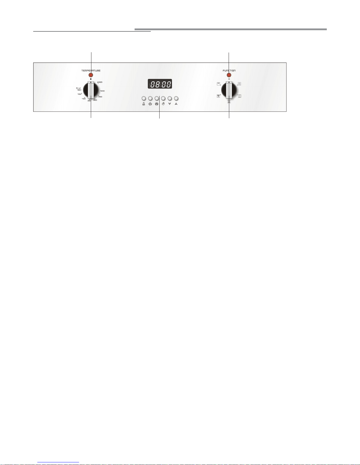
CONTROL PANEL (Fig. 1.1)
1. Oven thermostat knob
2. Function selector knob
3. Electronic programmer
4. Oven temperature indicator lamp
5. Power on indicator lamp
Fig. 1.1
control panel
1
4
5
3 2
Page 5
electronic programmer
A
U
T
O
Fig. 2.1
Fig. 2.2
The electronic programmer is a device
which groups together the following
functions:
• 12 hours clock with illuminated display
• Timer (up to 23 hours and 59 minutes)
•Program for automatic oven cooking
•Program for semi-automatic oven
cooking.
Description of the buttons:
Timer
Cooking time
End of cooking time
Manual position and cancellation of
the set cooking program
Advance the time for all programs
Decrease the time for all programs
and changing the frequency of the
audible signal.
Description of the illuminated
symbols:
AUTO - flashing - Programmer in auto-
matic position but not programmed
AUTO - always lit - Programmer in auto-
matic position with program set.
Automatic cooking taking place
Timer in operation
and AUTO - flashing - Program
error.
(The time of day lies between the
calculated cooking start and end
time).
Note:
Select a function by the respective button and, within 5 seconds, set the
required time with the / buttons
(“one-hand” operation).
A power cut makes the clock go to zero
and cancels the set programs.
ELECTRONIC TIMER
The timer program consists only of a
buzzer which may be set for a maximum
period of 23 hours and 59 minutes.
If the AUTO is flashing push the but-
ton.
To set the time, push the button and
the or until you obtain the
desired time in the panel (fig. 3.4).
Having finished the setting, the clock
hour will appear on the panel and the
symbol will be lit.
The countdown will start immediately and
may be seen at any moment on the panel
by simply pressing the button .
At the end of the time, the symbol
will be switched off and an intermittent
buzzer will go off; this can be stopped
by pressing any of the buttons.
SETTING THE FREQUENCY OF THE
AUDIBLE SIGNAL
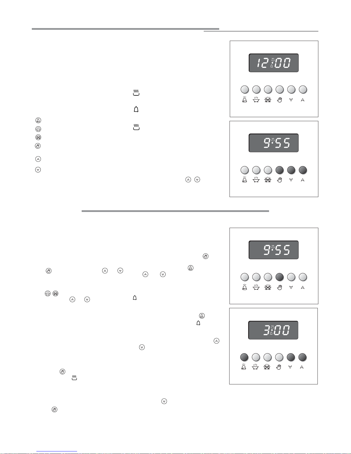
ELECTRONIC CLOCK (fig. 2.2)
The programmer is equipped with an
electronic clock with an illuminated display which indicates hours and minutes.
Upon immediate connection of the oven
or after a powercut, "12:00" will
flash on the display panel.
To set the hour it is necessary to push
the button and then the or
button until you have set the exact hour
(fig. 2.2).
Another way is to simultaneously push
the two buttons and at the same
time push the or button.
Note: The hour setting deletes any program.
NORMAL COOKING WITHOUT THE
USE OF THE PROGRAMMER
To manually use the oven, that is, without
the aid of the programmer, it is necessary
to cancel the flashing AUTO by pushing
the button (AUTO will be switched off
and the symbol will go on - Fig. 2.3).
Attention: If the AUTO is steadily lit (which
means a cooking program has already
been set), the program can be cancelled
and switched to manual by pushing the
button .
If the oven is switched on, you must
switch off manually.
ELECTRONIC TIMER
The timer program consists only of a
buzzer which may be set for a maximum
period of 23 hours and 59 minutes.
If the AUTO is flashing push the button.
To set the time, push the button and
the or until you obtain the
desired time in the panel (fig. 2.4).
Having finished the setting, the clock
hour will appear on the panel and the
symbol will be lit.
The countdown will start immediately and
may be seen at any moment on the panel
by simply pressing the button .
At the end of the time, the symbol
will be switched off and an intermittent
buzzer will go off; this can be stopped
by pressing any of the buttons (not
or ).
SETTING THE FREQUENCY OF THE
AUDIBLE SIGNAL
3 possible sounds can be selected by
pressing the button.
Fig. 2.3
Fig. 2.4
5
If the oven is switched on, you must
switch off manually.
Page 6
3. Set the temperature and the cooking
program (see the relevant sections).
Once the oven is programmed it will
switch on automatically at the right time
to stop the cooking at the desired end
time.
During cooking, the symbol remains
on.
By pushing the button you can see
the time that remains until the end of
cooking.
At the end of the cooking time the oven
will turn off automatically, the symbol will turn off, AUTO will flash and the
buzzer will sound, which can be turned
off by pushing any of the buttons (not
or ).
Turn the switch and temperature knobs
to "OFF" and put the programmer onto
“manual” by pressing the button.
Attention: A powercut will make the
clock go to zero and will cancel the set
programs.
After a powercut, "12:00" will flash
on the panel.
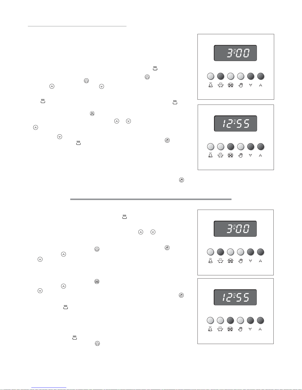
AUTOMATIC OVEN COOKING
To cook food automatically in the oven,
it is necessary to:
1. Set the length of the cooking time
2. Set the end of the cooking time
3. Set the temperature and the oven
cooking program.
1.Set the length of the cooking time
required by pushing the button
and the button to advance, or
to go back if you have passed the
desired time (fig. 2.5). The AUTO and
the symbol will be on.
2.Set the time you need the food to
stop cooking by pushing the button (the cooking time already added
to the clock time will appear), and the
button (fig. 2.6); if you pass the
desired time you can go back by
pushing the button.
After this setting, the symbol will
go off. If after this setting, the AUTO
flashes on the panel and a buzzer
goes off, it means there was an error
in the programming, that is the cooking cycle has been superimposed on
the clock. In this case, change the
end of cooking time or the cooking
time itself by following the instructions
above.
A
U
T
O
Fig. 2.5
A
U
T
O
Fig. 2.6
SEMI - AUTOMATIC COOKING
This is used to switch the oven off automatically after the desired cooking time
has elapsed.
There are two ways to set the semiautomatic cooking function:
1.Set the length of time you need to
cook the food by pushing the button and the button to advance, or
to go backwards (Fig. 2.7).
This sets the desired “stop” time.
or
2.Set the time you need the food to
stop cooking by pushing the button and the button to advance, or
to go backwards if you have
passed the desired time (Fig. 2.8).
AUTO and the symbol will be on.
Then set the temperature and the cooking program (see the relevant sections).
The oven is switched on and it will
switch off automatically at the end of
the desired time.
During cooking, the symbol remains
on and by pressing the button you
can see the time that remains until the
end of the cooking.
In this case the oven shall be switched
off manually.
At the end of the cooking, the oven and
the symbol will turn off, the AUTO
will flash and a buzzer will go off which
can be stopped by pushing any of the
buttons (not or ).
Turn the switch and temperature knobs
to "OFF" and put the programmer onto
“manual” by pressing the button.
A
U
T
O
Fig. 2.7
A
U
T
O
Fig. 2.8
6
Attention: A powercut will make the
clock go to zero and will cancel the set
programs.
After a powercut, "12:00" will flash
on the panel.
The cooking program may be cancelled at any time by pushing .
In this case the oven shall be switched
off manually.
The cooking program may be cancelled at any time by pushing .
Page 7
7
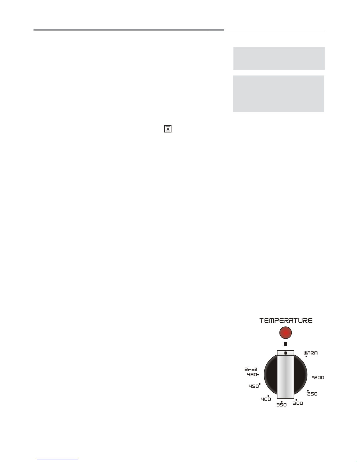
THERMOSTAT KNOB (fig. 3.1)
To turn on the heating elements of the oven, set function selector knob to the required
position and the thermostat knob to the desired temperature.
To set the temperature, turn the thermostat control knob indicator mark to the required
temperature.
The elements will turn on or off automatically which is determined by the thermostat.
The operation of the heating elements is signalled by a light placed on the control panel.
Attention: the oven door becomes
very hot during operation.
Keep children away.
OPERATING PRINCIPLES
Heating and cooking in the PLURIFUNCTION oven are obtained in the following ways:
a. by normal convection
The heat is produced by the upper and lower heating elements.
b. by semi-forced convection
The heat produced by the upper and lower heating elements is distributed throughout the oven by the fan.
c. by radiation
The heat is radiated by the infra-red element.
d. by radiation and ventilation
The radiated heat from the infra-red element is distributed throughout the oven by the
fan.
e. by ventilation
The food is defrosted by using the fan only without heat.
Fig. 3.1
GENERAL FEATURES
As its name indicates, this is an oven that presents particular features from an operational point of view.
In fact, it is possible to insert 4 different programs to satisfy every cooking need.
The 4 positions, thermostatically controlled, are obtained by 3 heating elements which
are:
- Lower element 1300 W
- Upper element 1000 W
- Infra-red element 2000 W
NOTE:
Upon first use, it is advisable to operate the oven at the maximum temperature (thermostat knob on 450°F) for 60 minutes in the position to eliminate possible traces of grease on the heating elements.
Repeat the operation for another 15 minutes with the infra-red element on as explained
in the BROILING chapters.
how to use the oven
WARNING:
The door is hot, use the handle.
During use the appliance becomes hot.
Care should be taken to avoid touching
heating elements inside the oven.
Page 8
8
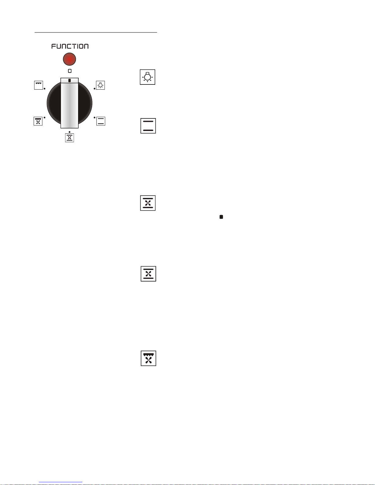
FUNCTION SELECTOR KNOB (fig. 3.2)
Rotate the knob clockwise to set the oven to one of the following functions:
OVEN LIGHT
By turning the function selector knob to this setting, the oven light will illuminate in the
oven cavity (15W).
The oven light will operate on all selected functions.
TRADITIONAL CONVECTION COOKING
The upper and lower heating elements are switched on.
The heat is diffused by natural convection and the temperature must be regulated
between 200 °F and 450 °F with the thermostat knob.
It is necessary to preheat the oven before introducing the foods to be cooked.
Recommended for:
For foods which require the same cooking temperature both internally and externally, i.
e. roasts, spare ribs, meringue, etc.
DEFROSTING FROZEN FOOD
With the thermostat knob in the " " OFF position only the oven fan is on.
The defrosting is done by simple ventilation without heat.
Recommended for:
To rapidly defrost frozen foods; 1 kilogram requires about one hour. The defrosting
times vary according to the quantity and type of foods to be defrosted.
CONVECTION COOKING WITH VENTILATION
The upper and lower heating elements and the fan turn on.
The heat coming from the top and bottom is diffused by forced convection.
The temperature must be regulated between 200 °F and 450 °F with the thermostat
knob.
Recommended for:
For foods of large volume and quantity which require the same internal and external
degree of cooking; for ex: rolled roasts, turkey, legs, cakes, etc.
VENTILATED BROILING
The infra-red element and the fan are on.
The heat is mainly diffused by radiation and the fan then distributes it throughout the
oven.
The temperature must be regulated between 200 °F and 450 °F with the thermostat
knob. It is necessary to preheat the oven for about 5 minutes.
For correct use see chapter “VENTILATED BROILING AND AU GRATIN”.
Always broil with the oven door closed.
It is recommended that you do not broil for longer than 30 minutes at any one
time.
Attention: the oven door becomes very hot during operation.
Keep children away.
Recommended for:
For broiling when a fast outside browning is necessary to keep the juices in, i. e. veal steak,
steak, hamburger,
etc.
Fig. 3.2
Page 9

9
BROILING
The infra-red heating element is switched on. The heat is diffused by radiation.
Use with the oven door closed and the thermostat knob must be regulated between
200 °F and 480 °F.
For correct use see chapter “BROILING”.
Recommended for:
Intense broiling action for cooking with the
infra-red element
and the rotisserie; browning,
crisping, “au gratin”, toasting, etc.
It is recommended that you do not broil for longer than 30 minutes at any one
time.
Attention: the oven door becomes very hot during operation.
Keep children away.
COOKING ADVICE
STERILIZATION
Sterilization of foods to be conserved, in full and hermetically sealed jars, is done in the
following way:
a. Set the switch to position
b. Set the thermostat knob to position 350 °F and preheat the oven.
c. Fill the dripping pan with hot water.
d. Set the jars onto the dripping pan making sure they do not touch each other and the
door and set the thermostat knob to position 250 °F.
When sterilization has begun, that is, when the contents of the jars start to bubble, turn
off the oven and let cool.
REGENERATION
Set the switch to position and the thermostat knob to position 250°F.
Bread becomes fragrant again if wet with a few drops of water and put into the oven for
about 10 minutes.
ROASTING
To obtain classical roasting, it is necessary to remember:
– that it is advisable to maintain a temperature between 350 and 400 °F.
– that the cooking time depends on the quantity and the type of foods.
COOKING DIFFERENT DISHES AT THE SAME TIME
With the function selector in position the ventilated oven allows you to
cook different types of food at the same time.
Fish, cakes and meat can be cooked together without the smells and flavours mixing.
The only precautions required are the following:
– The cooking temperatures must be as close as possible with a maximum difference
of 70° - 80°F between the different foods.
–Different dishes must be placed in the oven at different times according to the cook-
ing time required for each one. This type of cooking obviously provides a considerable saving on time and energy.
Page 10
10
VENTILATED BROILING AND “AU GRATIN”
Broiling may be done by selecting infra-red element+fan setting with the function selector knob, because the hot air completely envelops the food that is to be
cooked.
Set the thermostat knob between 200°F and 450 °F and after having preheated the
oven, simply place the food on the broiler pan (see chapter "CORRECT USE OF THE
BROILER PAN"). Close the door and let the oven operate until broiling is done.
Adding a few dabs of butter before the end of the cooking time gives the golden “au
gratin” effect.
Broiling with the oven door closed.
It is recommended that you do not broil for longer than 30 minutes at any one time.
Attention: the oven door becomes very hot during operation.
Keep children away.
BROILING
Set the function selector knob to position and the thermostat knob between 200°F
and 480 °F.
Leave to warm up for approximately 5 minutes with the door closed and then simply
place the food on the broiler pan (see chapter "CORRECT USE OF THE BROILER
PAN"). Close the door and let the oven operate until broiling is done.
Always br
oil with the oven door closed.
Broiling with the oven door closed and not for longer than 30 minutes at any one
time.
Attention: the oven door becomes very hot during operation.
Keep children away.
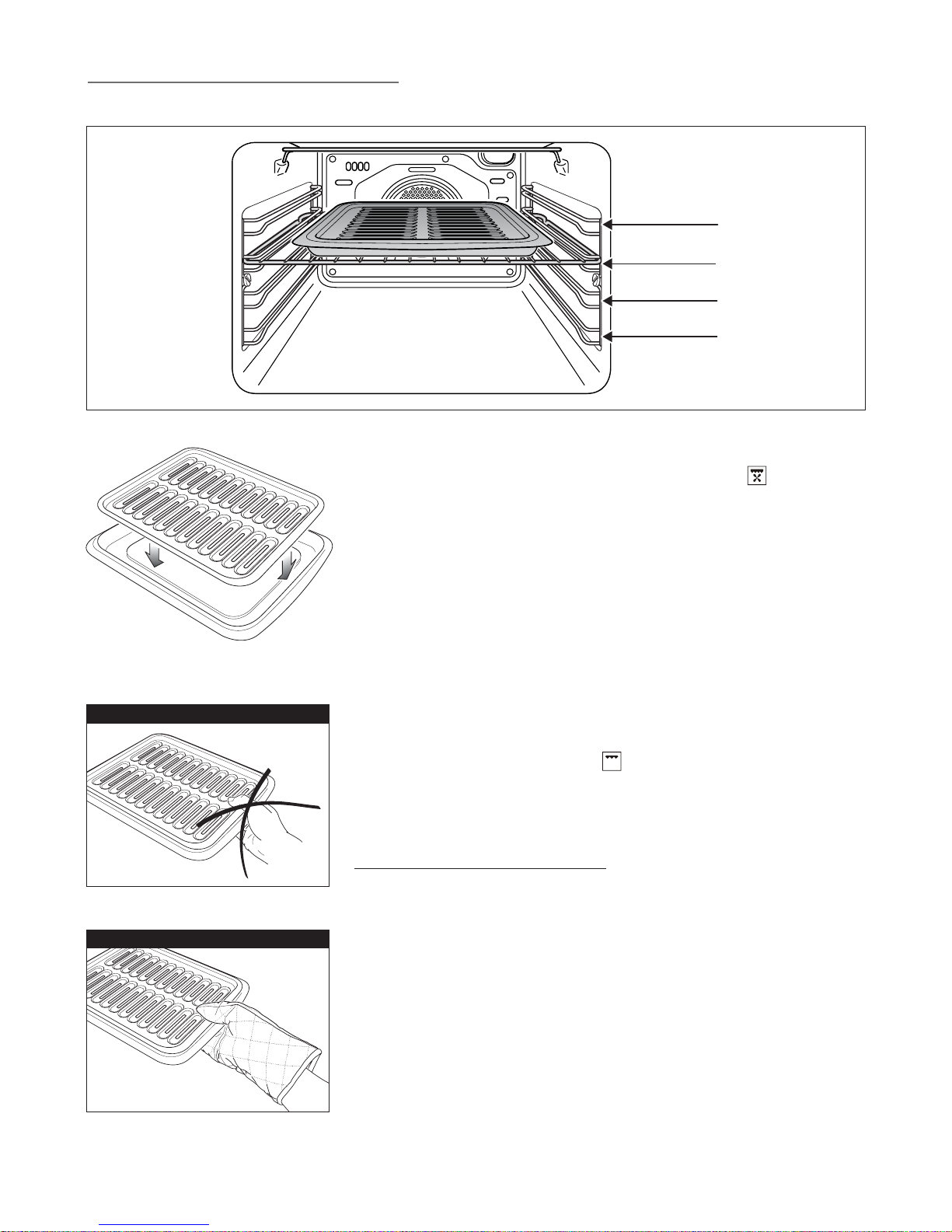
CORRECT USE OF THE BROILER PAN
• Position the shelf on the first or second level from the top (fig. 3.3).
• Place the food to be cooked above the broiler pan.
• Introduce the broiler pan (fig. 3.4) in the oven. The broiler pan should be placed above
the shelf and it should be centered with the broil element (fig. 3.3).
Do not broil without using the broiling pan.
Important: Use always suitable protective gloves when inserting/removing the
broiling pan, shelves, pans or other cooking utensils from the oven.
1° STEP
2° STEP
3° STEP
4° STEP
Fig. 3.3
WRONG
CORRECT
Fig. 3.4
Fig. 3.5
Fig. 3.6
Page 11

11
GENERAL RECOMANDATION
✓ Important: Before any operation of cleaning and maintenance disconnect the
appliance from the electrical supply.
✓ It is advisable to clean when the appliance is cold and especially for cleaning the
enamelled parts.
✓ Avoid leaving alkaline or acidic substances (lemon juice, vinegar, etc.) on the
surfaces.
✓ Avoid using cleaning products with a chlorine or acidic base.
The oven must always be cleaned after every use, using suitable products.
STAINLESS STEEL AND ALUMINIUM PARTS AND SILKSCREEN PRINTED SURFACES
✓ Clean using an appropriate product. Always dry thoroughly.
IMPORTANT: these parts must be cleaned very carefully to avoid scratching and
abrasion. You are advised to use a soft cloth and neutral soap.
Fig. 4.2
Fig. 4.1
OVEN FITTING OUT
– Assemble the wire racks to the oven walls using the 2 screws (Fig. 4.1).
– Slide in, on the guides, the shelves (fig. 4.2).
The shelf must be fitted so that the safety catch, which stops it sliding out, faces the
inside of the oven.
–To dismantle, operate in reverse order.
cleaning and maintenance
Do not use harsh abrasive cleaners or sharp metal scrapers to clean the oven
door glass since they can scratch the surface, which may result in shattering
of the glass.
Do not store flammable material in the oven.
WARNING
When correctly installed, your product meets all safety requirements laid down for
this type of product category. However special care should be taken around the
rear or the underneath of the appliance as these areas are not designed or intended to be touched and may contain sharp or rough edges, that may cause injury.
ENAMELLED PARTS
All the enamelled parts must be cleaned with a sponge and soapy water or other nonabrasive products.
Dry preferably with a microfibre or soft cloth.
Acidic substances like lemon juice, tomato sauce, vinegar etc. can damage the enamel if left too long.
INSIDE OF OVEN
The oven should always be cleaned after use when it has cooled down.
The cavity should be cleaned using a mild detergent solution and warm water.
Suitable proprietary chemical cleaners may be used after first consulting with the man-
ufacturers recommendations and testing a small sample of the oven cavity.
Abrasive cleaning agents or scouring pads/cloths should not be used on the cavity
surface.
NOTE: The manufacturers of this appliance will accept no responsibility for damage
caused by chemical or abrasive cleaning.
Let the oven cool down and pay special attention no to touch the hot heating
elements inside the oven cavity.
✓
Do not use a steam cleaner
because the moisture can get into
the appliance
thus
make it unsafe.
Page 12

12
Fig. 4.4
B
A
C
Fig. 4.4d
Fig. 4.4c
Fig. 4.4b
Fig. 4.4a
REMOVING THE OVEN DOOR
The oven door can easily be removed as follows:
– Open the door to the full extent (fig. 4.4a).
– Open the lever “A” completely on the left and right hinges (fig. 4.4b).
– Hold the door as shown in fig. 4.4.
– Gently close the door (fig. 4.4c) until left and right hinge levers “A” are hooked to part
“B” of the door (fig. 4.4b)
– Withdraw the hinge hooks from their location following arrow “C” (fig. 4.4d).
– Rest the door on a soft surface.
– To replace the door, repeat the above steps in reverse order.
REPLACING THE OVEN LIGHT
Before any maintenance is started involving electrical parts of the appliance, it must be
disconnected from the power supply.
– Let the oven cavity and the heating elements cool down;
– Switch off the electrical supply;
– Unscrew the protective cover (fig. 4.3);
– Unscrew and replace the bulb with a new one suitable for high temperatures (570°F)
having the following specifications: 220/240V 50/60Hz, 15W, E14
– Refit the protective cover
NOTE: Oven bulb replacement is not covered by your guarantee
1
2
Fig. 4.3
Page 13

13
INSTALLATION INSTRUCTIONS
GENERAL INFORMATION
1. Installation must conform with local codes.
2. WARNING: This appliance shall not be used for space heating. This information is
based on safety considerations.
3. Keep appliance area clear and free from combustible materials, gasoline, and other
flammable vapors.
4. Disconnect the electrical supply to the appliance before servicing.
5. When removing appliance for cleaning and/or service;
A. Disconnect AC power supply.
B. Carefully lift appliance out of cabinet cutout.
CAUTION: Use care in handling.
6.
Electrical Requirement
Electrical installation should comply with national and local codes.
REPLACEMENT PARTS
Only authorized replacement parts may be used in performing service on the
appliance. Replacement parts are available from factory authorized parts distributors.
Contact the nearest parts distributor in your area.
WARNING!
THIS APPLIANCE HAS TO BE INSTALLED BY A QUALIFIED INSTALLER.
Installation must conform with local codes.
Improper installation, adjustment, alteration, services, or maintenance can cause injury or property damage. Consult a
qualified installer or service agent. IMPORTANT: The use of suitable protective clothing/gloves is recommended when
handling, installing of this appliance.
WARNING: When correctly installed, your product meets all safety requirements laid down for this type of product
category.
However special care should be taken around the rear or the underneath of the appliance as these areas are not
designed or intended to be touched and may contain sharp or rough edges, that may cause injury.
WARNING!!
ELECTRICAL GROUNDING INSTRUCTIONS
The appliance must be electrically grounded in accordance with local codes or, in
the absence of local codes, with the National Electrical Code, ANSI/NFPA No.
70-latest edition, in Canada Canadian Electrical Code.
Installation should be made by a Iicensed electrician.
For personal safety, this appliance must be properly grounded.
Page 14

14
GENERAL INFORMATION
The oven can be fitted in standard units, minimum width and depth 23" 5/8 (600 mm).
Installation requires a compartment as illustrated in figures 5.1a and 5.1b.
On the lover side, the oven must lay on supports standing the oven weight.
A
B
E
D
L
C
I
F
F
H
G
A
B
D
E
C
Fig. 5.1a
Fig. 5.1b
installation to the cabinet
Ref. inches mm
A 23" 27/64 595
B 23" 27/64 595
C 21" 7/8 max 556 max
D 22" 3/64 max 560 max
E 25/32" 20
F 22" 3/64 560
G 23" 1/32 585
H 1" 31/32 50
I 23" 17/64 591
L 22" 7/16 min 570 min
Fig. 5.2
The oven should then be secured by 4 screws fitted into the holes provided at the
sides of the oven (Fig. 5.2). If you open the oven door, you will see some screw holes.
Remember the housing should not be free standing but be secured to the wall and/or
adjacent fittings.
NOTE
It is essential that when installing your oven, adequate
air circulation is available within the installation.
Inadequate air circulation may greatly impair the
performance of your oven and may affect adjacent
cabinets due to an increase in temperature.
Adjust the hinges of cabinet door adjacent to the oven
to allow a 5 - 7 mm gap between the furniture door
and the oven frame.
Page 15

15
Fig. 5.3
1" 11/64 (30 mm)
23" 5/8 min (600 mm min)
1" 31/32 (50 mm)
1" 31/32 (50 mm) 21" 21/32 (550 mm)
Fig. 5.4
To ensure internal ventilation, aeration
channels must be provided as illustrated
in the figures 5.3 and 5.4.
The walls surrounding the oven must
be made of heat-resistant material.
Taking care NOT to lift the oven by the
door handle.
OVEN DOOR
LOWER TRIM
AIR FLOW
Fig. 5.5
IMPORTANT:
To avoid damage to the lower trim
please note the following instructions.
The lower trim is designed to allow for
good air circulation and the correct opening of the oven door.
To ensure the trim is not damaged due to
the appliance being placed on the floor,
the appliance should be suitably supported as in above illustrations.
After installation the appliance door
should be slowly opened to ensure no
damage has occurred.
No responsibility for lower trim damage will be accepted if these instructions have not been followed.
Page 16

16
This appliance must be connected to a grounded, metallic permanent wiring system or a ground connector should be connected to the ground terminal or wire
lead on the appliance.
This appliance is manufactured with a frame connected, green or bare ground wire.
Connect the appliance cable to the junction box through the CSA or UL-listed conduit
connector. Complete electrical connection according to local codes and ordinances.
CONNECT WITH COPPER WIRE ONLY
✓
The flexible (4’) armoured cable should be connected directly to the junction box.
✓
Do not cut the conduit.
✓
A CSA or UL-listed conduit connector must be provided at the junction box.
✓
Do not ground to a gas pipe.
✓
Do not have a fuse in the grounding or neutral circuit.
✓
Fuse both supply (phase) lines.
✓
A time delay fuse or circuit breaker is recommended.
✓
Connect directly to the fused disconnect (or circuit breaker box) through flexible,
armored or non-metallic shealted, copper cable (with grounding wire).
✓
If codes permit and a separate grounding wire is used, it is recommended that a
qualified electrician determine that the grounding path and wire gauge is in
accordance with local codes.
This appliance does not require a neutral connection. If the appliance is to be
completely enclosed in a cabinet, feed the appliance cable through the opening
in the cabinet. Make the electrical connection following the appropriate steps for
your installation.
1. Disconnect the power supply.
2. Remove the junction box cover.
3. Connect the appliance cable to the junction box through the CSA or UL-listed conduit connector.
4. Connect the two black wires together with twist-on connectors.
5. Connect the two red wires together with twist-on connectors.
6. Connect electrical connection according to local codes and ordinances.
If local codes PERMIT connecting cabinet-grounding conductor to neutral white
wire in the junction box:
7. Connect the green appliance cable wire to the neutral (white) wire in the junction
box.
8. Replace the junction box cover.
OR If local codes DO NOT PERMIT connecting cabinet-grounding conductor to
neutral white wire in junction box:
7. Terminate neutral (white) wire in junction box.
8. Connect the green grounding appliance cable wire to a grounded wire in the junction box.
9. Replace the junction box cover.
OR If connecting to a four-wire electrical system:
7. Terminate neutral (white) wire in junction box.
8. Connect the green appliance cable wire to the green grounding wire in the junction
box.
electrical connection
TO AVOID ELECTRICAL SHOCK
HAZARD, BEFORE INSTALLING THE
APPLIANCE, SWITCH POWER OFF AT
THE SERVICE PANEL AND LOCK THE
PANEL TO PREVENT THE POWER
FROM BEING SWITCHED ON
ACCIDENTALLY.
WARNING
3-wire cable from
power supply
Black wires
Junction box
CSA or UL-listed
conduit connector
to appliance
Red wires
White
wire
Green & yellow
wire
White wire
Junction box
CSA or UL-listed
conduit connector
to appliance
Red wires
Black wires
Green & yellow
wires
4-wire cable from
power supply
Fig. 6.1
Fig. 6.2
Location of nameplate
Fig. 6.3
The manufacturer cannot be held responsible for possible inaccuracies due to printing or transcription errors in
the present booklet.
The manufacturer reserves the right to make all modifications to its products deemed necessary for manufacture
or commercial reasons at any moment and without prior notice, without jeopardising the essential functional and
safety characteristics of the appliances.
Page 17

16
Cet appareil doit être raccordé à un réseau permanent métallique, relié à la terre
ou il faudra raccorder une prise de terre à la borne de terre ou au câble de l’ap-
pareil.
Cet appareil est fabriqué avec un fil de terre vert ou nu, raccordé au châssis. Raccorder
le câble de l’appareil au bornier par un raccord de tube inscrit sur la liste de CSA ou
UL. Achever le raccordement électrique selon les réglementations et arrêtés locaux.
RACCORDER AVEC DU FIL DE CUIVRE SEULEMENT
✓
Le câble blindé flexible (4’) doit être raccordé directement au bornier.
✓
Ne pas couper le câble.
✓
Il faut prévoir un raccord de tube au bornier inscrit sur la liste de CSA ou UL.
✓
Ne pas prendre la terre sur une canalisation de gaz.
✓
Ne pas avoir de fusible sur le circuit de terre ou sur le neutre.
✓
Mettre un fusible sur les deux lignes d’alimentation (phases).
✓
Un fusible à action différée ou un disjoncteur est recommandé.
✓
Raccorder directement au coupe-circuit (ou au disjoncteur) par un câble en cuivre
flexible, blindé ou avec une gaine non-métallique (avec fil de terre).
✓
Si les réglementations l’autorisent et qu’un fil de terre séparé est utilisé, il est
recommandé de faire définir par un électricien qualifié la mise à la terre et le
diamètre du fil en conformité avec les réglementations locales.
Cet appareil ne nécessite pas un raccordement au neutre. Si l’appareil doit être
complètement enfermé dans un meuble, passer le câble de l’appareil par l’ou-
verture dans le meuble. Faire le raccordement électrique en suivant les étapes
adaptées à votre installation.
1. Débrancher l’alimentation du réseau.
2. Retirer le couvercle du bornier.
3. Raccorder le câble de l’appareil au bornier au moyen d’un raccord inscrit sur la liste
CSA ou UL.
4. Raccorder les deux fils noirs ensemble avec les connecteurs torsadés.
5. Raccorder les deux fils rouges ensemble avec les connecteurs torsadés.
6. Effectuer le branchement électrique selon les réglementations et arrêtés locaux.
Si les réglementations locales PERMETTENT de raccorder le conducteur de mise
à la terre du meuble au fil blanc neutre du bornier:
7. Raccorder le fil vert du câble de l’appareil au fil neutre (blanc) du bornier.
8. Replacer le couvercle du bornier.
OU Si les réglementations locales NE PERMETTENT PAS de raccorder le
conducteur de mise à la terre du meuble au fil blanc neutre du bornier:
7. Terminer le fil neutre (blanc) dans le bornier.
8. Raccorder le fil vert du câble de l’appareil au fil de terre du bornier.
9. Replacer le couvercle du bornier.
OU Si l’on se raccorde à un circuit électrique à quatre fils:
7. Terminer le fil neutre (blanc) dans le bornier.
8. Raccorder le fil vert du câble de l’appareil au fil vert de terre du bornier.
raccordement électrique
POUR EVITER UN RISQUE DE DECHARGE
ELECTRIQUE, AVANT D'INSTALLER
L'APPAREIL, COUPER L'ALIMENTATION
AU TABLEAU DE COMMANDE ET
VERROUILLER LE TABLEAU POUR
EMPECHER QUE L'ALIMENTATION NE
SOIT REBRANCHEE ACCIDENTEMENT.
ATTENTION
câble à 3 fils de
l'alimentation réseau
Fils noirs
Bornier
Raccord à
l'appareil
inscrit sur la
liste CSA ou UL
Fils rouges
Fil
blanc
Fils vert &
jaune
Fil blanc
Bornier
Raccord à
l'appareil
inscrit sur la
liste CSA ou UL
Fils rouges
Fils noirs
Fils vert &
jaune
câble à 4 fils de
l'alimentation réseau
Fig. 6.1
Fig. 6.2
Emplacement de la plaque
d'identification
Fig. 6.3
Le fabricant ne peut être tenu pour responsable de possibles inexactitudes dues à des erreurs d’impression ou
de transcription dans cette notice.
Le fabricant se réserve le droit d’apporter toutes les modifications à ses produits, jugées nécessaires pour des
raisons de fabrication ou commerciales, à tout moment et sans préavis, sans compromettre les caractéristiques
essentielles de fonctionnement et de sécurité des appareils.
Page 18

15
Fig. 5.3 Fig. 5.4
Pour garantir la ventilation intérieure, il
faut prévoir des conduits d’aération
comme illustré sur les figures 5.3 et 5.4.
Les parois qui avoisinent le four doi-
vent être faites d’un matériau résistant
à la chaleur.
Prendre soin de NE PAS soulever le
four par la poignée de la porte.
Fig. 5.5
IMPORTANT:
Pour éviter d’endommager la plinthe
inférieure, noter les instructions sui-
vantes.
La plinthe inférieure est conçue pour per-
mettre une bonne circulation d’air et l’ou-
verture correcte de la porte.
Pour être sûr que la plinthe ne soit pas
endommagée, lorsque l’appareil est
placé sur le sol, celui-ci devra être
appuyé de façon adéquate comme mon-
tré sur les figures ci-dessus.
Après l’installation, la porte de l’appareil
doit être ouverte lentement pour être sûr
de ne provoquer aucun dommage.
Aucune responsabilité pour la plinthe
inférieure ne sera acceptée, si ces ins-
tructions n’ont pas été suivies.
Porte du
four
PROFILE
INFERIEUR
Afflux d’air
1" 11/64 (30 mm)
23" 5/8 min (600 mm min)
1" 31/32 (50 mm)
1" 31/32 (50 mm) 21" 21/32 (550 mm)
Page 19

14
INFORMATION GENERALE
Le four peut être monté dans des meubles standard, largeur et profondeur min 23" 5/8
(600 mm).
Le montage nécessite un alvéole comme il est illustré sur les figures 5.1a et 5.1b.
Sur la partie basse, le four doit reposer sur des supports capables de supporter le poids
du four.
installation dans le meuble
A
B
E
D
L
C
I
F
F
H
G
A
B
D
E
C
Fig. 5.1a
Fig. 5.1b
Ref. mm
A 23" 27/64 595
B 23" 27/64 595
C 21" 7/8 max 556 max
D 22" 3/64 max 560 max
E 25/32" 20
F 22" 3/64 560
G 23" 1/32 585
H 1" 31/32 50
I 23" 17/64 591
L 22" 7/16 min 570 min
Fig. 5.2
Le four devrait ensuite être fixé par 4 vis insérées dans les trous prévus à cet effet sur
les côtés du four (fig. 5.2). Si vous ouvrez la porte du four, vous verrez des trous pour
les vis. Rappelez-vous que le boîtier ne devrait pas être autonome, mais plutôt fixé au
mur et/ou aux installations adjacentes.
REMARQUE
Lorsque vous installez votre four, il est essentiel que
la circulation d’air à l’intérieur de l’installation soit
adéquate.
Un circulation d’air inadéquate peut entraver
considérablement la performance de votre four et
endommager les armoires adjacentes étant donné la
température élevée.
Ajustez les charnières de la porte de l’armoire
adjacente au four de sorte qu’il y ait un espace de
5 à 7 mm entre la porte de l’armoire et le châssis du
four.
pouces
Page 20

13
INFORMATION GENERALE
1. L’installation doit être en conformité avec les réglementations locales.
2. ATTENTION: Cet appareil ne doit pas être utilisé pour chauffer l’ambiance. Cette
information est basée sur des considérations de sécurité.
3. Tenir la zone de l’appareil libre et dégagée de tout matériau combustible, essence,
et autres vapeurs inflammables.
4. Débrancher l’appareil de l’alimentation du réseau avant tout dépannage.
5. Lors d’un déplacement de l’appareil pour un nettoyage et/ou un dépannage;
A. Débrancher l’alimentation CA du réseau.
B. Soulever avec précaution l’appareil hors de la découpe du meuble.
ATTENTION: Le manipuler avec beaucoup de soin.
6.
Condition requise pour l’installation électrique
L’installation électrique doit respecter les réglementations nationales et locales.
PIECES DE RECHANGE
Seules les pièces de rechange autorisées peuvent être utilisées lors du service
d’entretien sur la table de cuisson. Les pièces de rechange sont disponibles auprès
de distributeurs de pièces agréés par l’usine. Contacter le distributeur de pièces le
plus proche de votre zone.
AVERTISSEMENT!
CET APPAREIL DOIT ÊTRE INSTALLÉ PAR UN INSTALLATEUR QUALIFIÉ.
Cet appareil doit être installé conformément aux codes locaux.
Une mauvaise installation, modification, réparation, ou un mauvais réglage ou entretien peuvent causer des blessures ou des
dommages matériels. Consultez un installateur qualifié ou un agent autorisé. IMPORTANT : L’utilisation de vêtements et de
gants de protection est recommandée lors de la manutention et l’installation de cet appareil.
AVERTISSEMENT : Lorsqu’il est correctement installé, votre appareil répond à toutes les exigences de sécurité prescrites
pour ce type de produit.
Toutefois, vous devez porter une attention particulière à l’arrière et au dessous de l’appareil, car ces endroits ne sont pas
conçus pour être touchés et certaines parties peuvent s’avérer tranchantes ou rugueuses et peuvent causer des blessures.
INSTRUCTIONS DE MISE À LA TERRE
L’appareil doit être mis à la terre conformément aux codes locaux en vigueur ou,
en l’absence de codes locaux, à la dernière édition du Code national de l’électri-
cité, ANSI/NFPA No. 70. AU CANADA : L’installation électrique doit être conforme
au Code canadien de l’électricité CSA C22.1, partie 1, en vigueur et/ou aux codes
locaux. L’installation devrait être effectuée par un électricien agréé.
Pour votre sécurité, cet appareil doit être correctement mis à la terre.
INSTRUCTIONS D’INSTALLATION
Page 21

12
Fig. 4.4
B
A
C
Fig. 4.4d
Fig. 4.4c
Fig. 4.4b
Fig. 4.4a
RETIRER LA PORTE DU FOUR
La porte du four peut être facilement retirée comme suit:
– Ouvrir la porte complètement (fig. 4.4a).
– Relever complètement le levier “A” sur les charnières gauche et droite (fig. 4.4b).
– Tenir la porte comme montré sur la fig. 4.4.
– Fermer la porte doucement (fig. 4.4c) jusqu’à ce que les leviers "A" gauche et droit
des charnières soient accrochés à la partie “B” de la porte (fig. 4.4b)
– Sortir les crochets des charnières de leur logement suivant la flèche “C” (fig. 4.4d).
– Poser la porte sur une surface molle.
– Pour replacer la porte, répéter les étapes ci-dessus dans l’ordre inverse.
REMPLACEMENT DE LA LAMPE DU FOUR
Avant de commencer tout entretien sur les parties électriques de l’appareil, il faut le
déconnecter de l’alimentation du réseau.
– Laisser refroidir l’enceinte du four et les éléments chauffants;
– Débrancher l’alimentation électrique;
– Dévisser le couvercle de protection (fig. 4.3);
– Dévisser et remplacer la lampe par une nouvelle résistant aux températures élevées
(570°F) et ayant les caractéristiques suivantes: 220/240V 50/60Hz, 15W, E14
–Replacer le couvercle de protection
REMARQUE: Le remplacement de la lampe du four n’est pas couvert par la garantie.
1
2
Fig. 4.3
Page 22

11
RECOMMANDATIONS GENERALES
✓ Important: Avant toute opération de nettoyage et d’entretien, débrancher
l’appareil de l’alimentation électrique.
✓ Il est conseillé de nettoyer l’appareil, lorsqu’il est froid, en particulier en ce qui
concerne les parties émaillées.
✓ Eviter de laisser des produits alcalins ou acides (jus de citron, vinaigre, etc.) sur
les surfaces.
✓ Eviter d’utiliser des produits de nettoyage à base de chlore ou d’acide.
Le four doit toujours être nettoyé après chaque usage à l’aide de produits adaptés.
PARTIES EN ACIER INOXYDABLE ET ALUMINIUM ET SUR-
FACES IMPRIMEES EN SERIGRAPHIE
✓ Nettoyer à l’aide d’un produit approprié. Sécher toujours soigneusement.
IMPORTANT: ces parties doivent être nettoyées avec beaucoup de soin pour éviter
des griffes et leur abrasion. Il est conseillé d’utiliser un chiffon doux et du savon
neutre.
Fig. 4.2
Fig. 4.1
EQUIPEMENT DU FOUR
– Accrocher les supports de guidage latéraux aux parois du four à l’aide des 2 vis
(Fig. 4.1).
– Introduire, en les faisant glisser sur les guides, les grilles (fig. 4.2).
La grille doit être montée de façon à ce que l’ergot de sécurité, qui l’empêche de glis-
ser vers l’extérieur, soit dirigé vers l’intérieur du four.
– Pour le démontage, procéder dans l’ordre inverse.
nettoyage et entretien
N’utilisez jamais de produits de nettoyage agressifs ou abrasifs ou de grattoirs
en métal tranchant pour nettoyer la vitre de la porte du four : ceci risquerait
en effet de rayer la surface, ce qui pourrait faire éclater le verre.
Ne utilisez pas une machine à jet de vapeur parce que de l’humidité peut
pénétrer dans l’appareil et le rendre dangereux.
Ne placer aucun matériau inflammable dans le four il pourrait prendre feu pen-
dant le fonctionnement.
AVERTISSEMENT
Lorsqu’il est correctement installé, votre appareil répond à toutes les exigences
de sécurité prescrites pour ce type de produit.
Toutefois, vous devez porter une attention particulière à l’arrière et au dessous
de l’appareil, car ces endroits ne sont pas conçus pour être touchés et certaines
parties peuvent s’avérer tranchantes ou rugueuses et peuvent causer des bles-
sures.
PARTIES EMAILLEES
Toutes les parties émaillées ne doivent être lavées qu’avec une éponge et de l’eau
savonneuse ou avec d’autres produits spéciaux non abrasifs.
De préférence essuyer avec un tissu souple.
INTERIEUR DU FOUR
Le four doit être nettoyé chaque fois après utilisation, lorsqu il est tiède. La cavité doit
être nettoyée avec une solution de détergent doux et de l’eau tiède. Des produits chi-
miques nettoyants peuvent être utilisés après avoir consulté les recommandations du fabri-
cant et après avoir testé un petit échantillon de la cavité du four. Des agents de nettoyage
abrasifs ne doivent pas être utilisés sur la surface de la cavité.
–
REMARQUE: Le fabricant de cet appareil n’acceptera aucune responsabilité pour les
dommages causés par l’utilisation des produits chimiques ou abrasifs.
–
Laisser le four refroidir et faire de l'attention à ne pas toucher les éléments chauds
à l'intérieurdu four.
✓
Page 23

10
1° NIVEAU
2° NIVEAU
3° NIVEAU
4° NIVEAU
Fig. 3.3
EXACT
INEXAT
Fig. 3.4
Fig. 3.5
Fig. 3.6
GRIL AVEC VENTILATION ET “AU GRATIN”
La grillade peut être faite par sélection de l’élément infra-rouge + ventilateur, c’est-à-
dire en plaçant le sélecteur de fonction sur
, pour que l’air chaud enveloppe
complètement les aliments qui sont à cuire.
Placer le bouton du thermostat entre 200°F et 450 °F et après avoir préchauffé le four,
placer simplement les aliments sur le plateau de grilleur (voir chapitre "UTILISATION
CORRECTE DU PLATEAU DE GRILLEUR"). Fermer la porte et laisser fonctionner le four
jusqu’à ce que les aliments soient dorés. Ajouter quelques noisettes de beurre avant la
fin du temps de cuisson, pour produire un effet doré de "gratiné”.
Griller avec la porte du four fermée.
Il est recommandé de ne pas utiliser le gril plus de 30 minutes à chaque fois.
Attention : la porte du four devient très chaude pendant le fonctionnement.
Tenir les enfants éloignés.
GRILLER
Placer le sélecteur de fonction sur la position et le bouton du thermostat entre
200°F et 480 °F.
Laisser chauffer pendant environ 5 minutes, la porte fermée, et introduire les aliments
à cuire sur le plateau de grilleur (voir chapitre "UTILISATION CORRECTE DU PLATEAU
DE GRILLEUR"). Fermer la porte et laisser fonctionner le four jusqu’à ce que les ali-
ments soient dorés.
Griller toujours, la porte du four fermée.
Griller, la porte du four fermée et pas plus de 30 minutes à chaque fois.
Attention : la porte du four devient très chaude pendant le fonctionnement.
Tenir les enfants éloignés.
UTILISATION CORRECTE DU PLATEAU DE GRILLEUR
• Introduire la grille dans le premier ou le deuxième niveau de haut (fig. 3.3).
• Placez les aliment a cuire au-dessus du plateau de grilleur.
• Introduire le plateau de grilleur (fig. 3.4) dans le four. Le plateau de grilleur devrait être
placé au-dessus de la grille et il devrait être centré avec l’élément infra-rouge (fig. 3.3).
Ne grillez pas sans utiliser le plateau de grilleur.
Important : Employez toujours des gants protecteurs appropriés en insérant/ enle-
vant dans le four le plateau de grilleur, grilles, casseroles ou autres outils de cui-
sine.
Page 24

9
GRIL
L’élément infra-rouge est allumé. La chaleur est diffusée par radiation.
Utiliser avec la porte du four fermée; le bouton du thermostat doit être réglé entre 200
°F et 480 °F.
Pour une utilisation correcte, voir le chapitre “GRILLER”.
Recommandé pour:
Effet intense de grillade, pour cuire avec l’élément infra-rouge et le tourne-broche; faire
dorer, rendre croustillant, “au gratin”, griller du pain, etc.
Il est recommandé de ne pas utiliser le gril plus de 30 minutes à chaque fois.
Attention: la porte du four devient très chaude pendant le fonctionnement.
Tenir les enfants éloignés.
CONSEILS DE CUISSON
STERILISATION
La stérilisation d’aliments à conserver, dans des bocaux pleins et hermétiquement fer-
més, se fait de la manière suivante:
a. Placer le sélecteur sur la position
b. Placer le bouton du thermostat sur la position 350 °F et préchauffer le four.
c. Remplir la lèchefrite avec de l’eau chaude.
d. Placer les bocaux dans la lèchefrite en vérifiant qu’ils ne se touchent pas entre eux
ou la porte et placer le bouton du thermostat sur la position 250°F.
Lorsque la stérilisation a commencé, c’est-à-dire, lorsque le contenu des bocaux com-
mence à bouillonner, éteindre le four et laisser refroidir.
REGENERATION
Placer le sélecteur sur la position
et le bouton du thermostat sur la position
250°F.
Le pain redevient parfumé s’il est mouillé avec quelques gouttes d’eau et placer dans
le four pendant environ 10 minutes.
ROTIR
Pour obtenir un rôtissage classique, il faut se rappeler:
– qu’il est conseillé de maintenir la température entre 350 et 400 °F.
– que le temps de cuisson dépend de la quantité et du type d’aliments.
CUIRE DIFFERENT PLATS EN MEME TEMPS
Le sélecteur de fonction étant sur la position
, le four ventilé vous permet de
cuire différents types d’aliments en même temps.
Du poisson, des gâteaux et de la viande peuvent être cuits ensemble sans que les
arômes et les goûts se mélangent.
Les seules précautions demandées sont les suivantes:
– Les températures de cuisson doivent être aussi voisines que possible, avec une dif-
férence maximale de 70° - 80°F entre les différents aliments.
– Les différents plats doivent être placés dans le four à des moments différents selon le
temps de cuisson requis pour chacun. Ce type de cuisson procure évidemment une
économie considérable de temps et d’énergie.
Page 25

8
SELECTEUR FONCTIONS (fig. 3.2)
Tourner le bouton dans le sens des aiguilles d’une montre pour régler le four sur une
des fonctions suivantes:
ECLAIRAGE DU FOUR
En tournant le sélecteur de fonctions sur ce réglage, l’éclairage du four s’allume dans
l’enceinte du four (15W).
L’éclairage du four fonctionne sur toutes les fonctions sélectionnées.
CUISSON PAR CONVECTION TRADITIONNELLE
Les éléments chauffants supérieur et inférieur sont branchés.
La chaleur est diffusée par convection naturelle et la température doit être réglée entre
200 °F et 450 °F à l’aide du bouton thermostat.
Il est nécessaire de préchauffer le four avant d’introduire les mets à cuire.
Recommandé pour:
Pour aliments qui demandent la même température de cuisson à l’intérieur et à l’exté-
rieur, par ex. rôtis, côtelettes de porc, meringues, etc.
DECONGELATION D’ALIMENTS CONGELES
Le bouton du thermostat étant sur la position arrêt " " (OFF), seul le ventilateur
du four
est en marche.
La décongélation se fait par simple ventilation sans chaleur.
Recommandé pour:
Pour décongeler rapidement des aliments gelés; 1 kilogramme demande environ une
heure. Les temps de décongélation varient selon la quantité et le type d’aliments à
décongeler.
CUISSON PAR CONVECTION AVEC VENTILATION
Les éléments chauffants supérieur et inférieur, ainsi que le ventilateur sont branchés.
La chaleur venant du haut et du bas est diffusée par convection forcée.
La température doit être réglée entre 200 °F et 450 °F à l’aide du bouton du thermo-
stat.
Recommandé pour:
Pour aliments de gros volume et grande quantité, qui demandent le même degré de
cuisson interne et externe; par ex.: rôtis roulés, dinde, gigots, gâteaux, etc.
GRIL AVEC VENTILATION
L’élément infra-rouge et le ventilateur sont en marche.
La chaleur est surtout diffusée par irradiation et le ventilateur la distribue ensuite dans
tout le four.
La température doit être réglée entre 200 °F et 450 °F avec le bouton du thermostat. Il
faut préchauffer le four pendant environ 5 minutes.
Pour une utilisation correcte, voir chapitre “GRIL AVEC VENTILATION ET AU GRATIN”.
Toujours utiliser le gril, la porte du four fermée.
Il est recommandé de ne pas utiliser le gril plus de 30 minutes à chaque fois.
Attention: la porte du four devient très chaude pendant le fonctionnement.
Tenir les enfants éloignés.
Recommandé pour:
Pour griller lorsqu’un brunissage extérieur rapide est nécessaire pour conserver le jus
à l’intérieur, par ex. steak de veau, steak, hamburger, etc.
Fig. 3.2
Page 26

7
BOUTON DU THERMOSTAT (fig. 3.1)
Pour brancher les éléments chauffants du four, placer le sélecteur de fonctions sur la
position requise et le bouton du thermostat sur la température souhaitée.
Pour régler la température, mettre l’index du bouton de commande du thermostat sur
la température souhaitée.
Les éléments s’allumeront ou s’éteindront automatiquement, selon ce que détermine le
thermostat.
Le fonctionnement des éléments chauffants est signalé par une lumière placée sur le
bandeau de commande.
Attention: la porte du four devient
très chaude pendant le fonction-
nement.
Te nir les enfants éloignés.
PRINCIPES DE FONCTIONNEMENT
Le chauffage et la cuisson dans le four PLURIFONCTION sont obtenus de la manière
suivante:
a. par convection normale
La chaleur est produite par les éléments chauffants supérieur et inférieur.
b. par convection semi-forcée
La chaleur produite par les éléments chauffants supérieur et inférieur.
est distribuée dans tout le four par le ventilateur.
c. par rayonnement
La chaleur est irradiée par l’élément infra-rouge.
d. par rayonnement et ventilation
La chaleur irradiée par l’élément infra-rouge est distribuée dans tout le four par le
ventilateur.
e. par ventilation
Les aliments sont décongelés en utilisant le ventilateur seul, sans chaleur.
Fig. 3.1
CARACTERISTIQUES GENERALES
Comme son nom l’indique, c’est un four qui présente des caractéristiques particulières
d’un point de vue opérationnel.
En fait, il est possible d’insérer 4 programmes différents pour répondre à chaque besoin
de cuisson.
Les 4 positions, contrôlées par thermostat, sont obtenues par 3 éléments chauffants
qui sont:
- Elément inférieur 1300 W
- Elément supérieur 1000 W
- Elément infra-rouge 2000 W
REMARQUE:
A la première utilisation, il est conseillé de faire fonctionner le four à la température
maximale (thermostat sur 450°F) pendant 60 minutes sur la position pour
éliminer les traces possibles de graisse sur les éléments chauffants.
Répéter l’opération pendant 15 autres minutes avec l’élément infra-rouge allumé
comme expliqué au chapitre GRIL.
comment utiliser le four
ATTENTION:
La porte est chaude, utiliser la poignée.
Pendant l'utilisation l'appareil devient
chaud. Faire de l'attention à ne pas tou-
cher les éléments chauds à l'intérieur
du four.
Page 27

6
CUISSON SEMI-AUTOMATIQUE
Sert à éteindre le four automatique
après un temps de cuisson désiré.
Pour exécuter cette cuisson il y a deux
façons:
1. Déterminer le temps de durée de la
cuisson en pressant le poussoir et le
poussoir pour avancer, ou le pous-
soir pour revenir si le temps désiré a
été dépassé (fig. 2.7).
ou
2. Déterminer l’heure d’arrêt de la cuisson
en pressant le poussoir et le poussoir
pour avancer, ou le poussoir pour
revenir si le temps désiré a été dépassé
(fig. 2.8).
L’inscription AUTO et le symbole s’al-
lumeront.
Afficher, après, la température et la
fonction en agissant sur les manettes
adéquates (voir chapitre spécifique).
Le four s’allumera immédiatement et
après I’écoulement du temps de cuis-
son le four s’arrêtera automatiquement.
Pendant la cuisson le symbole reste
allumé et en pressant le poussoir on
visualise le temps qui manque à I’arrêt
de la cuisson.
À la fin de la cuisson le four s’arrêtera,
le symbole s’éteindra, la légende
AUTO clignotera et le signal acoustique
sera activé.
Celui-ci peut être interrompu en pres-
sant I’un des poussoirs (non ou ).
Mettre aussi les manettes du four à
I’allure éteint et mettre en “manuel” le
programmateur en pressant le poussoir
.
CUISSON AUTOMATIQUE DANS
LE FOUR
Pour exécuter la cuisson automatique des
aliments dans le four, il est nécessaire de:
1. Déterminer le temps de durée de la
cuisson
2. Déterminer I’heure d’arrêt de la cuis-
son
3. Déterminer la température et la fonc-
tion de cuisson.
On effectuera ces opérations de la
manière suivante:
1.
Déterminer le temps de durée de la
cuisson en pressant le poussoir et
le poussoir pour avancer, ou
pour revenir si le temps désiré a été
dépassé
(fig. 2.5).
La légende AUTO et le symbole
s’alIumeront.
2. Déterminer I’heure d’arrêt de la cuis-
son en pressant le poussoir (ceci
fait paraître le temps de cuisson déjà
sommé à I’heure de la montre) et le
poussoir si I’heure a été dépas-
sée, reculer en pressant le poussoir
(fig. 2.6).
Après le réglage, le symbole
s’éteindra. Si après le réglage, dans
le cadran du programmateur la
légende AUTO clignote et le signal
acoustique s’active, cela signifie qu’il
y a eu une erreur de programmation,
c’est-à-dire que le cycle de cuisson a
été superposé à I’heure de la montre.
Dans ce cas, modifier l’heure d’arrêt
de la cuisson ou le temps de durée
3.Afficher, après, la température et la
fonction, en agissant sur les manettes
adéquates (voir chapitre spécifique).
En ce moment le four est programmé
et tout fonctionnera automatique-
ment, c’est à dire que le four s’allu-
mera automatiquement au bon
moment, de façon à exécuter la cuis-
son de durée établie et à terminer à
I’heure programmée.
Pendant la cuisson le symbole
reste allumé et en pressant le pous-
soir on visualise le temps qui
manque à I’arrêt de la cuisson.
Après I’écoulement du temps de cuis-
son le four s’arrêtera automatique-
ment, le symbole s’éteindra, la
légende AUTO clignotera et le signal
acoustique sera activé, celui-ci peut
être interrompu en pressant I’un des
poussoirs (non ou ).
Mettre aussi les manettes du four à
I’allure éteint et mettre en “manuel” le
programmateur en pressant le pous-
soir .
Attention: L’interruption de I’énergie
électrique provoque la mise à zéro de la
montre et I’oblitération des tous les pro-
grammes.
Après I’interruption "12:00" clignote
sur le cadran.
de la cuisson.
A
U
T
O
Fig. 2.5
A
U
T
O
Fig. 2.6
A
U
T
O
Fig. 2.7
A
U
T
O
Fig. 2.8
Attention: L’interruption de I’énergie
électrique provoque la mise à zéro de la
montre et I’oblitération des tous les pro-
grammes.
Après I’interruption "12:00" clignote
sur le cadran.
Le programme peut être annulé en
tout moment, en pressant les pous-
soir .
Dans ce cas, le four doit être éteint
manuellement.
Le programme peut être annulé en
tout moment, en pressant les pous-
soir .
Dans ce cas, le four doit être éteint
manuellement.
Page 28

Decrease the program time and
changing the frequency of the
audible signal.
5
programmateur électronique
End of cooking time
Manual position and cancellation of
the set cooking program
Advance the time for of all pro-
grams
Decrease the program time and
changing the frequency of the
audible signal.
(The time of day lies between the
calculated cooking start and end
time).
Note:
Select a function by the respective but-
ton and, within 5 seconds, set the
required time with the / buttons
(“one-hand” operation).
A power cut makes the clock go to zero
and cancels the set programs.
Le programmateur électronique est un
dispositif qui regroupe les fonctions sui-
vantes:
– Horloge 12 heures à display lumineux
– Minuterie (jusqu’à 23 heures et 59
minutes)
– Programme pour cuisson au four auto-
matique
– Programme pour cuisson au four semi
automatique.
DESCRIPTION DES BOUTONS:
Minuterie
Temps de cuisson
Heure de fin de cuisson
Passage en manuel et annulation
des programmes insérés
Avancement des nombres
de toutes les fonctions
Mise en arrière du nombre
de toutes les fonctions et
réglage de la tonalité du signal
sonore
Description des symboles lumineux:
AUTO - clignotant - Programmateur en
automatique mais non program-
mé ( on ne peut allumer le four)
AUTO - allumé sans clignotant -
Programmateur en automatique
ou semi automatique avec pro-
gramme inséré.
Programmateur en manuel ou cuis-
son automatique en cours
Minuterie en marche
et AUTO
- clignotants et signal
sonore -
Erreur de programmation
(le temps de cuisson dépasse
l’heure de fin de cuisson).
Remarque: La programmation (avec
une seule main) se fait en appuyant la
touche correspondante à la fonction
désirée et après l’avoir relachée, il suffit
dans les 5 secondes qui suivent de
commencer à placer le temps avec les
touches ou .
Le programmateur reviendra au Zéro à
chaque interruption d’énergie électrique.
MONTRE ELECTRONIQUE (fig. .2)
Le programmateur est muni d’une
montre électronique dont les chiffres
lumineux indiquent les heures et les
minutes.
Au premier branchement électrique du
four ou après une interruption de cou-
rant, "12:00" clignote dans la
fenêtre du programmateur.
Pour régler l’heure, il faut appuyer sur la
touche , puis sur la touche
ou
jusqu’au réglage de l’heure exacte
(fig.
.2).
Une autre façon d’opérer consiste à
appuyer en même temps sur les deux
touches , tout en appuyant sur la
touche
ou .
Remarque: Le réglage de l’heure com-
porte l’annulation de programmes
éventuels en cours ou programmés.
2
2
CUISSON NORMALE SANS L’EMPLOI DU
PROGRAMMATEUR
Pour utiliser manuellement le four, c’est à
dire sans I’emploi du programmateur, il est
nécessaire d’annuler la légende clignotan-
te AUTO, en pressant le poussoir
(AUTO s’éteindra et le symbole s’allu-
mera)(fig. 2.3).
Attention: Si la légende AUTO ne clignote
pas (cela indique qu’un programme de
cuisson a été déjà inséré), en pressant le
poussoir on optienne l’annulement du
programme et la commutation en manuel.
MINUTEUR ELECTRONIQUE
(fig. .4)
La fonction minuteur se compose
uniquement d’un avertisseur acoustique
qui peut être réglé pour une période
maximale de 23h 59min.
Si la légende AUTO clognote, presser le
poussoir
Pour régler le temps, il suffit de presser
le poussoir et le poussoir ou
jusqu’à ce qu’on obtienne le temps
désiré (fig. .4).
Dès que le réglage est terminé, I’heure
de la montre reparaîtra sur le cadran et
le symbole s’allumera.
Le compte à rebours commencera tout
de suite et il peut être visualisé dans le
cadran en tout moment, en pressant
seulement le poussoir
.
À I’échéance du temps le symbole
s’éteindra et un signal acoustique inter-
mittent sera activé; celui-ci peut être
interrompu, en pressant I’un des pous-
soirs (non ou ).
2
2
REGLAGE DE LA TONALITE DU SIGNAL
SONORE
Lorsqu’on appuie sur la touche , on
obtient à la suite trois tonalités du son.
Le dernier signal entendu reste program-
mé.
A
U
T
O
Fig. 2.1
Fig. 2.2
Fig. 2.3
Fig. 2.4
Si le four est allumé, il doit être éteint
manuellement.
Si le four est allumé, il doit être éteint
manuellement.
Page 29

4
BANDEAU DE COMMANDES (Fig. 1.1)
1. Bouton thermostat four
2. Sélecteur de fonctions
3. Programmateur électronique
4. Voyant température four
5. Voyant alimentation réseau
Fig. 1.1
bandeau de commandes
1
4
5
3 2
Page 30

3
PRECAUTIONS ET RECOMMANDATIONS IMPORTANTES
✓ Après avoir déballé l’appareil, contrôler qu’il n’est pas endommagé. Si vous
avez quelques doutes, ne l’utilisez pas et contactez votre fournisseur ou un
technicien professionnellement qualifié.
✓ Les éléments de l’emballage (par ex. sacs en plastique, mousse de
polystyrène, clous, lanières d’emballage, etc.) ne doivent pas être laissés
traînés alentour, à la portée facile d’enfants, car ils pourraient être source de
sérieux ennuis.
✓ Le matériel d’emballage est recyclable et est marqué du symbole de
recyclage .
✓ N’essayez pas de modifier les caractéristiques techniques de l’appareil, car
cela pourrait le rendre d’une utilisation dangereuse.
✓ Le fabricant ne peut pas être considéré responsable pour les dommages
causés par un usage déraisonnable, impropre ou imprudent de l’appareil.
✓ Si vous décidez de ne plus utiliser cet appareil (ou décidez de remplacer un
plus vieux modèle), avant de vous en débarrasser, il est recommandé de le
rendre inopérant de façon appropriée en accord avec les réglementations
sanitaires et de protection environnementale, en s’assurant en particulier que
toutes les pièces potentiellement dangereuses sont rendues inoffensives,
spécialement vis-à-vis d’enfants qui pourraient jouer avec de vieux appareils.
✓ L’appareil doit être installé et les raccordements électriques faits par un
technicien qualifié en conformité avec les réglementations locales en vigueur
et selon les instructions du fabricant.
A LA PREMIÈRE MISE EN SERVICE DU FOUR
Il est conseillé d’effectuer les opérations suivantes:
✓ Assembler l’intérieur du four, comme décrit dans le chapitre “Nettoyage et
entretien”.
✓ ALLUMER le four vide à la température maximale pendant environ deux heures pour
éliminer toutes traces de graisse et d’odeur des composants.
✓ Laisser le four refroidir, couper l’alimentation électrique, puis nettoyer l’intérieur du
four avec un chiffon trempé dans de l’eau et un détergent neutre et sécher
soigneusement.
PRECAUTIONS ET RECOMMANDATIONS IMPORTANTES
POUR L’UTILISATION D’APPAREILS ELECTRIQUES
L’utilisation de tout appareil électrique implique la nécessité de suivre une série
de règles fondamentales. En particulier:
✓ Ne jamais toucher l’appareil avec des mains ou des pieds mouillés;
✓ Ne pas faire fonctionner l’appareil, les pieds nus;
✓ Ne pas laisser des enfants ou des personnes handicapées utiliser l’appareil
hors de votre surveillance.
Le fabricant ne peut être tenu pour responsable des dommages causés par un
usage impropre, incorrect ou déraisonnable de l’appareil.
INSTRUCTIONS POUR L’UTILISATEUR
Page 31

2
Cher Client,
Merci d’avoir fait cette acquisition et avoir donné votre préférence à
notre produit.
Les précautions et recommandations de sécurité ci-après reportées
sont données pour votre propre sécurité et celle des autres. Elles vous
procureront aussi un moyen d’utiliser à plein les caractéristiques
offertes par votre appareil.
Conservez ce manuel précieusement. Il peut vous être utile dans le
futur, à vous ou à quelqu’un d’autre, au cas où surgiraient des doutes à
propos de son fonctionnement.
Cet appareil ne doit être utilisé que pour l’usage pour lequel il a été
explicitement conçu, c’est-à-dire pour cuire des aliments. Tout autre
forme d’emploi doit être considérée comme inappropriée et même dan-
gereuse.
Le fabricant décline toute responsabilité dans le cas de dommage dû
à un usage impropre, incorrect ou illogique de l’appareil.
Cet appareil a été conçu et fabriqué uniquement pour la cuisson domestique des aliments et
ne convient pas à l’usage non ménager. Cet appareil ne devrait donc pas être utilisé dans un
environnement commercial.
La garantie de l’appareil sera annulée s’il est utilisé dans un environnement non domestique,
c’est-à-dire un environnement semi-commercial, commercial, ou communautaire.
Page 32

IMPORTANT – LIRE ET SUIVRE
✓ Avant de commencer, lire ces instructions soigneusement et dans leur totalité.
✓ Ne pas retirer du produit étiquettes, avertissements ou plaques fixées de façon permanente. Cela
pourrait annuler la garantie.
✓ Observer toutes les réglementations et usages locaux et nationaux.
✓ S’assurer que ce produit est convenablement mis à la terre.
✓ L’installateur doit laisser ces instructions à l’utilisateur qui les conservera pour l’utilisation
de l’inspecteur local et pour s’y reporter ultérieurement.
L’installation électrique doit être en conformité avec les Réglementations Electriques
Nationales ANIS/NFPA70 – dernière édition et/ou les réglementations locales.
AU CANADA: L’installation électrique doit être en conformité avec les Réglementations
Electriques Canadiennes en vigueur CSA C22.1 Partie 1 et/ou les règlements locaux
FRANÇAIS
INSTALLATION, MODE D'EMPLOI
FOUR ENCASTRABLE
DIMENSIONS: 595 mm (L) x 580 mm (P) x 595 mm (H)
MODELE
F6M9PX F6..5SP4XE.UA
23"
27
/64 (L) x 22"
53
/64 (P) x 23"
27
/64 (H)
Cod. 310576
F&P IT cod. 1103399-ß1
 Loading...