


Berkel PRO LINE VS25, PRO LINE VS30, PRO LINE GL30, PRO LINE GL30 AUTO, PRO LINE SLC 300 operation manual
...PRO LINE SERIES
PRO LINE VS25 - VS30 PRO LINE GL30
PRO LINE GL30 AUTO
PRO LINE SLC 300 - 330 - 350 PRO LINE SLC 350A
PRO LINE XS 25 - 30
EN
IT
DE
FR
CS
DA
USER MANUAL
MANUALE D’USO GEBRAUCHSANLEITUNG MANUEL D’INSTRUCTIONS
NÁVOD K POUŽITÍ
BETJENINGSVEJLEDNING
ES
NL
NO
PT
RO
SV
MANUAL DEL USUARIO HANDLEIDING BRUKSANVISNING MANUAL DE INSTRUÇÕES MANUAL DE INSTRUCTIUNI BRUKSANVISNING

(A) |
(B) |
(C) |
SAFETY |
|
|
(D) |
(E) |
|
(F) |
(G) |
|
(L) |
(M) |
(N) |
(O) |
3
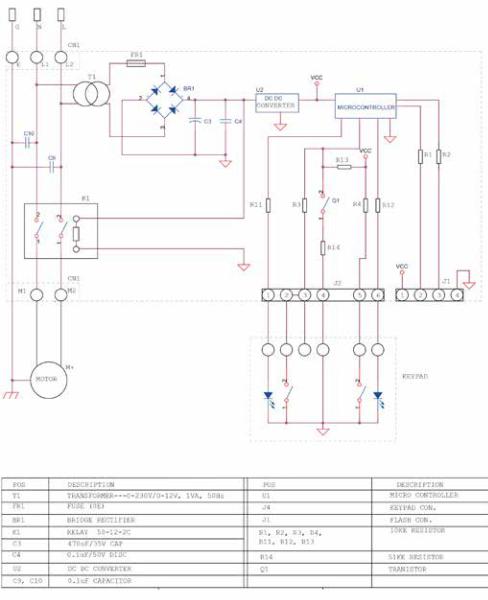
Fig. 2
Abb. 2
Obr. 2
Afb. 2
Bild 2
4
5
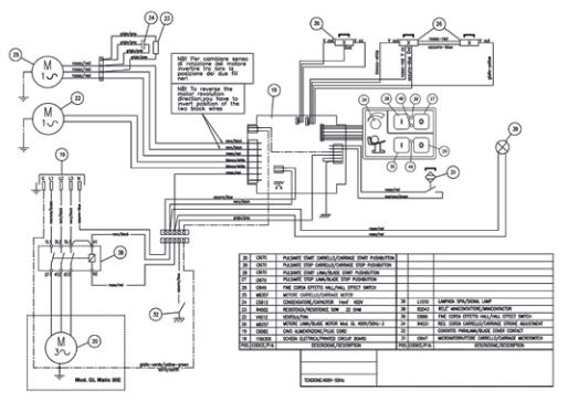
Fig. 2
Abb. 2
Obr. 2
Afb. 2
Bild 2
6
|
|
|
|
|
|
ANTITAMPER |
|
|
|
|
FU1 |
|
|
|
|
|
T1 |
ARR |
GREEN |
STOP NC |
|
|
|
|
|||
|
|
|
|
|
|
|
|
|
|
|
COM |
|
|
|
|
|
|
MAR |
GREEN |
START NO |
G |
N |
L |
|
|
|
|
|
|
|
|
U |
|
|
|
|
N |
|
V |
|
|
|
|
|
|
|
|
|
|
|
PLUG |
|
|
|
|
|
|
M |
|
|
|
|
|
|
|
|
|
|
SLC 300-330-350 |
|
|
|
|
|
|
ANTITAMPER |
|
|
|
|
FU1 |
|
|
|
|
|
T1 |
ARR |
GREEN |
STOP NC |
|
|
|
|
|||
|
|
|
|
|
|
|
|
|
|
|
COM |
|
|
|
|
|
|
MAR |
GREEN |
START NO |
G |
N |
L |
|
|
|
|
|
|
|
|
U |
|
|
|
|
N |
|
V |
|
|
|
|
|
|
|
|
|
|
|
RED |
PLUG |
|
|
|
|
|
|
|
|
|
|
|
|
M |
|
|
|
|
|
|
S4 |
|
|
|
|
|
|
|
|
|
|
SLC 300-330-350 |
Fig. 1 - Abb. 1 - Obr. 1 - Afb. 1 - Bild 1 |
|
|
|
|
||
7
T1
X1
G N L
LINE
L
KM1
N
INPUT 230V 50-60Hz
FU1
LOAD
|
|
|
ANTITAMPER |
|
|
|
CONTROL PANEL |
||
F.C. |
WHITE |
+ |
- |
LED POWER |
LED |
|
|||
F.C. |
|
|
||
WHITE |
|
|
|
|
ARR |
GREEN |
|
|
STOP NC |
|
YELLOW |
|
|
|
COM |
|
|
|
|
YELLOW |
|
|
|
|
MAR |
GREEN |
|
|
START NO |
LAMP |
WHITE |
|
|
|
LAMP |
BROWN |
+ |
- |
LED START |
LED |
|
|||
|
|
|
||
U |
|
|
|
|
|
|
|
|
|
BROWN
V
SINGLE PHASE MOTOR 230V 50-60Hz
RED |
BLACK |
X1 |
PLUG |
|
|
C1 |
CAPACITOR 8µF 450V BEG300B |
MGREY
M1 1 |
LIGHT BLUE |
C1 |
|
HOLES TOLLERANCE |
SPECIFICATED) RO |
|
|
(IF NOT OTHERWISE |
|||
|
|
|
|
POSITION |
0.1 |
|
|
|
|
DIAM. |
+0.1 |
|
|
|
|
0 |
|
|
|
|
|
THIS DRAWING IS EXCLUSIVE PROPERTY OF VAN BERKEL INTERNATIONAL S |
|
|
|
|
|
UNAUTHORIZED USE OR COPIES OF THIS DRAWING COULD BE PERSECUTE |
|
|
|
QUOTE |
SCOST. MATERIALE/material: |
|
|
|
|
> |
-< |
mm |
|
|
|
|
|
|
6 |
+ |
STATO |
MATERIALE/material status: |
|
|
|
|
|
|
|
|
- 0.1 |
SLC 300-330Van Berkel-350Intern |
|||||
|
|
|
|
6 |
50 |
+ |
|
|
|
||
|
|
|
|
- 0.2 |
|
|
|
21040 |
Oggiona |
||
|
|
|
|
50 |
120 |
+ |
FINISH: |
|
Heat treatment: |
|
|
|
|
|
|
- 0.3 |
|
|
|||||
|
|
|
|
|
|
|
|
|
ANTITAMPER |
|
|
|
|
|
|
FU1 |
|
|
|
|
|
|
|
|
|
|
T1 |
ARR |
|
|
|
GREEN |
|
STOP NC |
|
|
|
|
|
|
|
|
|
|
|||
|
|
|
|
|
|
|
|
|
|
|
|
|
|
|
|
COM |
|
|
|
|
|
|
|
|
|
|
|
MAR |
|
|
|
GREEN |
|
START NO |
|
G |
N |
L |
|
|
|
|
|
|
|
|
|
|
|
|
|
U |
|
|
|
|
|
|
|
|
|
N |
|
V |
|
|
|
|
|
|
|
|
|
|
|
|
|
|
|
|
|
|
|
|
|
RED |
|
|
|
|
|
|
|
|
|
|
|
M |
|
|
|
|
|
|
|
|
|
|
|
S4 |
PLUG |
|
|
|
|
|
|
|
|
|
|
|
|
|
|
|
|
|
|
|
|
|
|
S4 |
HEATING PROTECTION |
|
|
|
|
|
|
|
|
|
|
|
|
|
|
|
|
|
|
SLC 300-330-350 |
|
Fig. 1 - Abb. 1 - Obr. 1 - Afb. 1 - Bild 1
8
|
|
|
|
ANTITAMPER |
L3 |
|
|
|
|
|
|
V |
|
|
|
|
U |
MA |
GREEN |
|
|
CO |
|
|
G |
|
|
|
|
|
|
AR |
GREEN |
|
|
|
|
|
|
|
|
|
C |
|
|
2 |
|
M |
|
|
|
|
|
|
|
1 |
|
|
|
|
|
T1 |
|
|
|
3M |
|
|
|
|
|
|
|
SLC 300-330-350 |
|
THREE PHASE MOTOR 1 KW U-V-W |
|
|
|
THREE PHASE POWER SUPPLY L1-L2-L3
ANTITAMPER
CONTROL PANEL
L3
X1 L2
L1
G
L3 |
|
W |
|
|
L2 |
|
X1 V |
L |
|
L1 |
K1 |
U |
MA |
|
CO |
||||
|
|
3 |
AR |
|
|
|
C |
2 |
M |
|
|
1 |
|
|
T1 |
BROWN |
+ |
- |
BROWN |
LED |
|
WHITE |
|
|
GREEN |
|
|
YELLOW |
|
|
YELLOW |
|
|
GREEN |
|
|
WHITE |
+ |
- |
|
||
WHITE |
LED |
|
LED START START N.O. STOP N.C.
LED STOP
BLACK |
RED |
BLUE |
|
M |
BLACKRED |
M1 3 |
BLUE |
|
SELF RESTORE FUSE
|
|
|
HOLES TOLLERANCE |
|
ROUG |
|
|
|
|
(IF NOT OTHERWISE |
SPECIFICATED) |
||
|
|
|
POSITION |
|
0.1 |
|
|
|
|
DIAM. |
|
+0.1 |
|
|
|
|
|
0 |
|
|
|
|
|
|
|
|
|
|
|
|
THIS DRAWING IS EXCLUSIVE PROPERTY OF VAN BERKEL INTERNATIONAL S.r.l. |
|||
|
|
|
UNAUTHORIZED USE OR COPIES OF THIS DRAWING COULD BE PERSECUTED BY |
|||
QUOTE |
SCOST. MATERIALE/material: |
|
|
|
||
> |
-< |
mm |
|
|
|
|
|
6 |
+ |
STATO MATERIALE/material status: |
|
|
|
|
- 0.1 |
SLC 300Van-330Berkel-350Internation |
||||
6 |
50 |
+ |
|
|||
- 0.2 |
|
|
21040 |
Oggiona S. St |
||
Fig. 1 - Abb. 1 - Obr. 1 - Afb. 1 - Bild 1
9
SLC 350A
SLC 350A
Fig. 1 - Abb. 1 - Obr. 1 - Afb. 1 - Bild 1
10
SLC 350A
SLC 350A
Fig. 1 - Abb. 1 - Obr. 1 - Afb. 1 - Bild 1
12
EN
USER MANUAL: Electrical Slicers Pro Line
MODELS:
GL30, GL30AUTO, VS25, VS30, SLC 300-330-350, SLC 350A, XS 25, XS 30
7 |
10 |
11 |
|
|
|
6 |
|
18 |
13
13b
2 |
|
|
|
|
3 |
|
|
|
|
|
|
1 |
5 |
|
|
16 |
|
|
|
|
|||
4 |
|
||||
|
|
||||
|
|
17 |
|
9 |
8 |
12 |
|
|
|
||
|
|
|
|
||
|
|
|
|
|
|
20
19
14 |
15 |
21 |
|
1a 1b 1c 1d 1e
|
23 |
1h |
1g 1f |
22 |
|
|
|
|
|
|
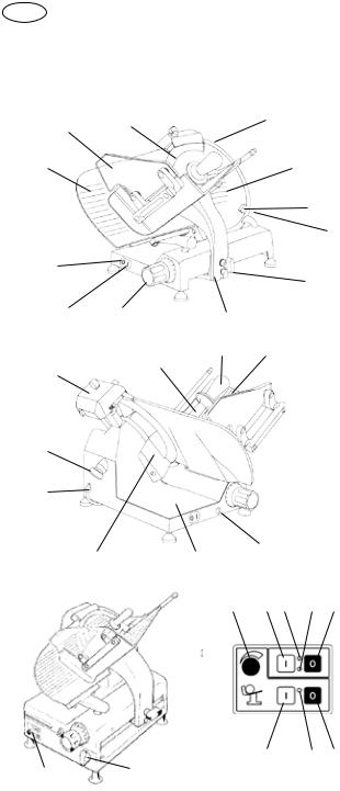
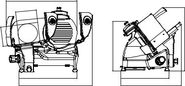
Fig. 1
GENERAL PLAN
OF THE MACHINE
1.Start button
2.Stop button
3.Plate locking knob
4.Foot
5.Thickness adjustment knob
6.Thickness gauge plate
7.Safety guards
8.Meat table
9.Product press holder
10.Blade
11.Safety ring (blade guard)
12.Sharpener
13.Blade cover knob
13b. Blade cover knob for XS
14.Slice guard
15.Baseplate
16.Carriage
17.Product holder
18.Blade guard disk
19.Power cable
20.Blade cover tension rod
21.Carriage bar oiler (where it is present)
GL30 AUTO
22.Control pushbuttons
23.Carriage release handle
1a. Product holder extension adjustment knob
1b. Start blade
1c. Led - Start blade
1d. Led - Power supply
1e. Stop blade
1f. Stop meat table
1g. Led - Start meat table
1h. Start meat table
13

|
13 |
8 |
12 |
|
|
14 |
|
|
|
|

 5
5
19 |
20 |

 3
3
|
|
1 |
|
2 |
17 |
|
|
|
|
||
|
|
|
|
|
|
|
|
4 |
|
|
|
|
|
11 |
|
|
|
|
18 |
|
10 |
|
13 |
24 |
|
|
|
||
|
|
|
|
||
|
|
|
|
|
14 
15 |
21 |
7 |
|
|
|
|
6 |
|
1a |
1b 1c |
1d 1e |
|
22 |
23 |
1h |
1g 1f |
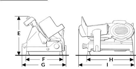
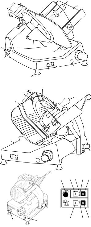
Fig. 2 |
|
|
|
|
|
|
|
|
SLC 300 - 330 - 350
SLC 350A
MAIN
COMPONENTS
1.Start button
2.Stop button
3.Slice thickness regulating knob
4.Foot
5.Handle for plate pushing
6.Carriage
7.Plate locking knob
8.Meat table
10.Top clamp
11.Blade cover (blade cover)
12.Sharpener
13.Product holder handle
14.Thickness gauge plate
15.Casing
17.Lubricating point for guide bars
18.Blade
19.Blade cover tension rod
20.Slice deflector
21.Blade guard ring
24. Meat table safety guard
SLC 350A
22.Control pushbuttons
23.Carriage release handle
1a. Product holder extension adjustment knob
1b. Start blade
1c. Led - Start blade
1d. Led - Power supply
1e. Stop blade
1f. Stop meat table
1g. Led - Start meat table
1h. Start meat table

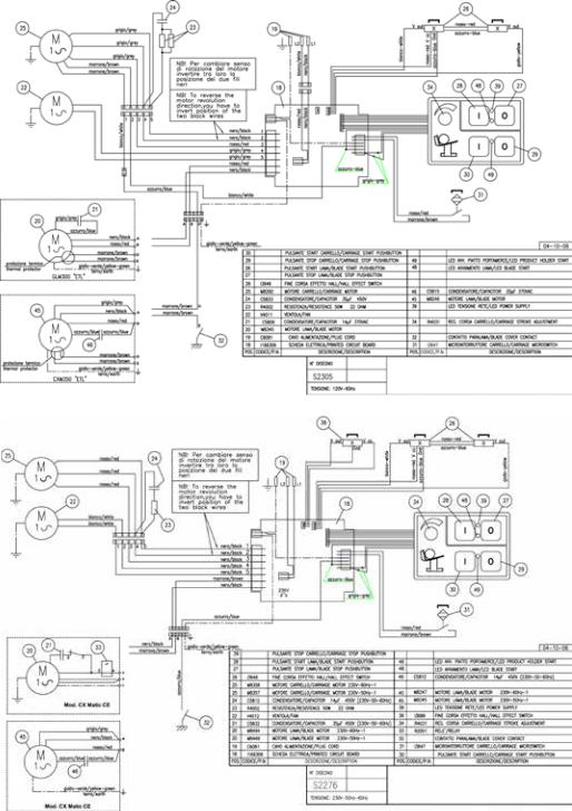
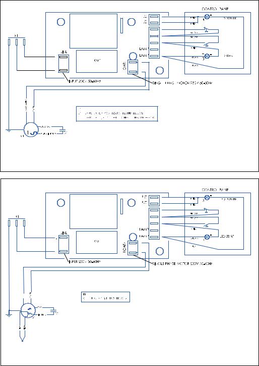
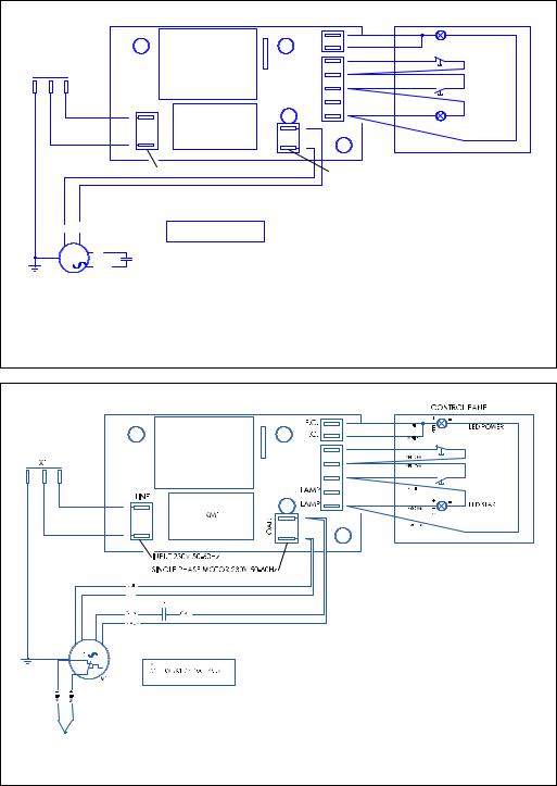
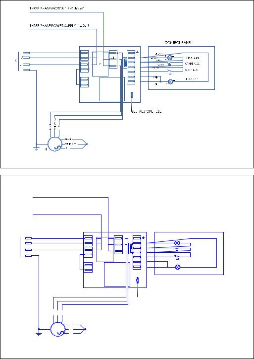
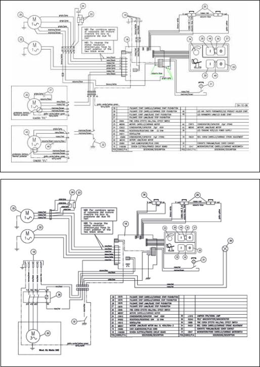
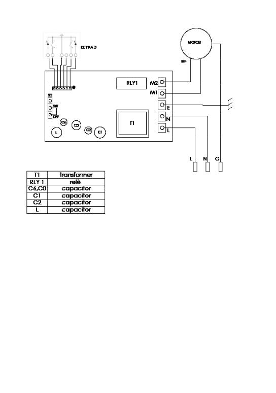
DESCRIPTION
Circular blade professional slicer machine suitable for cutting only the food products of the types and within the dimensional limits indicated in this manual. The main parts of the machine are shown in the general component diagram reported in Fig. 1. Electrical diagrams are reported in Fig. 2.
DECLARATION
OF CONFORMITY
The machines described in this manual comply with Directives 2006/42/CE, 2006/95/ CE, 2004/108/CE, 2003/108/ CE, 2011/65/CE, Regulation (EC) 1935/2004 and related harmonized standards as EN 1974:1998 +A1, EN60204-1, EN60335-1, EN60335-2-64.
SAFETY
Pay attention to the following basic safety precautions:
--read all the instructions before using the machine;
--this product is not intended to be used by children;
--operate the machine only if properly trained and in perfect psycho-physical conditions.
--do not use the machine in any way other than what indicated in this manual;
--use the machines only in full structural, mechanical and system efficiency;
--install the machine in conformity to the instructions indicated in the “Installation” section;
--install the machine in a location out of the reach of personnel unauthorized to operate it
and especially out of the reach of minors;
--stayhighlyconcentratedwhen using the machine and avoid any distraction during use;
--do not allow the machine to be used by others who have not read and fully understood the content of this manual;
--do not wear baggy clothing or clothing with open sleeves;
--do not allow anyone else, other than the operator, to approach during product cutting operations;
--do not remove, cover or modify the tags located on the machine body and, in case of damage of these, replace them promptly;
--do not remove the transparent guards and do not modify or bypass any mechanical and electrical protective devices; --slice only the permitted products, do not attempt cuts on prohibited type products;
--always keep clean and dry the sliced product resting surface, the work area all around the machineandtheoperatorfloor area;
--do not use the machine as a resting surface and do not place any objects on it other than food used for cutting operations;
--do not use the slicer when, due to normal wear, the distance between the edge of the blade and the blade guard ring exceeds 6 mm. In this case, contact the manufacturer or to one of the Authorized Service Centers to change the blade; --do not use the machine with temporary or non-insulated cables, power strips or extension cords;
--periodically check the condition of the power supply cord on the machine body. When
necessary, have qualified personnel replacing it.
--immediately stop the machine in the event of a defect, abnormal operation, suspicion of breakdown, incorrect movement, unusual noises;
--before cleaning or carrying out maintenance, disconnect the machine from the electrical supply;
--use protective gloves for cleaning and maintenance operations;
--place and remove the goods to be sliced on the sliding plate only with the carriage completely pulled back and with the thickness adjustment knob placed in the safety position (on the 0 position) (Fig. A);
--for movement of the meat table during cutting operations use only the handle located on the arm or the product presser grip;
--never put your hands on the food product while slicing. Always keep your hands behind the protection devices and far from the blade;
--use of cutting accessories which were not provided by the manufacturer with the machine is prohibited.
The manufacturer declines any responsibility coming from inappropriate use, modifications and/or repairs carried out by the user or unauthorized personnel, use of replacement parts that are not original or not specific for the machine model.
The machine shall not be used in open areas and/or areas which are exposed to atmospheric agents and in environments with vapors, fumes or corrosive and/or abrasive powders, with risk of fire or explosion and in any case where the
15

use of antiexplosive components is required.
Operating conditions:
-Temperature from -5°C to +40°C
-Max. humidity 95%
DO NOT SLICE:
-frozen food products;
-food products with bones;
-any other product not intended for food use;
-contact of the aluminum components with strongly acidic or highly salted foods is not recommended.
Thesafetyringaroundtheblade is made in conformity to European standards EN 1974:1998 +A1 but, in order to allow the sharpening operations, the protection in the sharpening area may not entirely eliminate the risk of cutting.
!WARNING! During the blade cleaning and sharp-
ening operations, pay extra attention to keep your hands as far as possible from the unprotected area. Use of protective gloves is recommended.
INSTALLATION
OF THE MACHINE
Install the machine on a flat, smooth and dry surface suitable for supporting the weight of the machine itself plus the products to be sliced.
!WARNING! Verify that there are no obstacles to
the meat table travel and to the loading of products.
The machine must be installed in the immediate vicinity of an EEC standard outlet connect-
ed to an electrical supply system which is in conformity with the prevailing regulations for:
-magneto-thermic protection;
-automatic differential switch;
-earthing system.
Before carrying out electrical hook up verify that the characteristics of the electrical power supply is in accordance with those indicated on the machine information plate.
OPERATION
MANUAL OPERATION – FOR MODELS VS25 – VS30 – GL30
-XS 25 - XS 30:
!WARNING! Risk of injury from sharp blade! Check
that the thickness adjustment knob (5) is in the safety position (on the 0 position) (Fig. A).
1.Pull the meat table (8) all the way back (towards the operator) in the loading position (Fig. B);
2.lift the product holder (17) into the standby position;
3.place the product to be sliced on the meat table near the operator side wall. Block it with the product holder applying slight pressure;
4.adjust the slice thickness. Activate the blade (10) by pressing the start button (1). Grip the product holder handle (9) and start an alternative cutting motion;
5.at the end of the cutting operations return the thickness adjustment knob to the safety position and pull the meat table back. Stop the blade motion by pressing the stop button (2).
AUTOMATIC OPERATION – FOR MODELS GL30A:
1. Rotate the carriage release grip (3) 180° anticlockwise (3);
2.Press the blade start button (1b);
3.Press the meat table start button (1h).
4.To select the most suitable carriage travel for the shape of the product to be sliced, rotate the carriage extension (1a) in the clockwise direction to elongate and in the opposite direction to shorten (Fig. C).
!WARNING! Do not place hands near the carriage
or meat table while the machine is in operation.
Once cutting has been completed, press the meat table stop button (1f): the blade will keep running while the meat table will stop at the travel limit on the operator side, ready for more cutting.
If you press the blade stop button (n. 1e), the meat table will stop in its current position.
MANUAL OPERATION FOR SLC 300-330-350, SLC 350A: set the product to be sliced on the plate against the wall of the meat table, near the edge of the table on the operator side; lock using the product press holder, applying pressure; in the gravity version, the product will press against the plate from the force of its own weight;
-- adjust the slice thickness with the special knob (3). Activate the blade (18) by pressing the start button (1). Grip the product holder handle (13) and start an alternative cutting motion;
-- on gravity models, when the weight or size of the goods do not allow a proper cutting for reasons of gravity, use the product holder handgrip;
16

-- at the end of the cutting operations return the thickness adjustment knob to the safety position and pull the meat table back. Stop the blade motion by pressing the stop button (2); -- move the sliding meat table away from the gauge plate and remove the product.
AUTOMATIC OPERATION (ONLY FOR SLC 350A):
1.Rotate the carriage release grip (3) 180° anticlockwise (3);
2.Press the blade start button (1b);
3.Press the meat table start button (1h).
4.To select the most suitable carriage travel for the shape of the product to be sliced, rotate the carriage extension (1a) in the clockwise direction to elongate and in the opposite direction to shorten (Fig. C).
!WARNING! Do not place hands near the carriage
or meat table while the machine is in operation.
Once cutting has been completed, press the meat table stop button (1f): the blade will keep running while the meat table will stop at the travel limit on the operator side, ready for more cutting.
If you press the blade stop button (n. 1e), the meat table will stop in its current position.
CLEANING
Before using, clean the machine at least once a day - or more often if necessary - and always after a long period of inactivity.
!WARNING! Risk of electric shock! Before cleaning,
disconnect the plug from the electricalmainssocketandplace the thickness adjustment knob in the safety position.
!WARNING! Risk of injury from sharp blade! Check
that the thickness adjustment knob (5) is in the safety position (on the 0 position) (Fig. A). DO NOT DISHWASH
Products for cleaning:
use only water and biodegradable mild detergent, using a soft, spongy cloth and a semi-rigid nylon brush for the sharp areas of the plate and the product holder. Do not clean the machine with jets of water or steam or similar methods.
Dismantling:
-the meat table:
1)free the meat table, rotating the presser clamp in the clockwise direction. With the thickness adjustment knob in the safety position, pull back the carriage all the way until the travel limit toward the operator: a metallic click notifies the operator that the meat table is locked; 2) remove the product presser;
3)extract the product holder unit sliding the meat table from its support (Fig. D);
-the blade cover:
1)rotating in the anticlockwise direction, loosen the blade cover tension rod grip;
2)to raise the blade disc, press on the grip in the direction of the blade; 3) lift the blade cover (Fig. E);
-the slice deflector:
loosen the fixing screw (if is present) and remove the slice deflector (Fig. F).
!WARNING: Risk of injury
from sharp blade! For the cleaning operations of the sharp areas of the plates, the product holder and the blade, use of protective gloves is also recommended.
Cleaning:
-the blade: press a damp cloth on the surface of the blade and move it slowly from the center toward the outside on the blade cover side and the opposite side (Fig. G). In the same way dry it using a dry cloth;
-the safety ring: use a soft brush to clean the area between the blade and the safety ring;
-the machine body: use a damp cloth or a sponge, rinsing water. Dry carefully.
MAINTENANCE
Blade Sharpening
Frequency and duration of sharpening depend on the use of the equipment.
!WARNING! If the machine is equipped with its spe-
cific optional sharpener, follow the instructions. Otherwise, contact the manufacturer or to one of the Authorized Service Centers (see SERVICE).
For sharpening, follow the instructions:
1.Position the thickness adjustment knob in the safety position (Fig. A);
2.Pull the meat table all the way back (Fig. B);
3.Lift the sharpening device cover (Fig. L);
4.Pull the release lever and rotate the sharpening device in the direction of the blade (Fig. M);
5.Leave the lever. The device will lock in the correct position;
17

6.Press the start button;
7.Slightly rotate the lever, bringing the two wheels in contact with the blade and maintain the position for about 10-15 seconds (Fig. N), Sharpening and deburring occur simultaneously;
7b. For XS 25 - XS 30 - VL25 - VL
30models press the sharpening button for 10-15 seconds (Fig. O1). Press the deburring button for 3-5 seconds (Fig. O2).
8.Stop the blade motion by pressing the stop button;
9.move the device back to the initial position;
10.Lower the sharpening device guard cover;
11.Proceed with cleaning the slicer.
Lubrication
After a regular period of use, it may be necessary to lubricate the carriage guides. We recommend executing this operation every 3 months. For lubrication, only use acid free oil (we recommend Vaseline oil). Do not use vegetable oil.
SERVICE
No user-serviceable parts are inside. Refer servicing to qualified personnel. All the repair and replacement operations (like blade replacement, replacement of the motor belt, replacement of the sub-basap- late electrical system components, repair of structural parts, repair and/or re-placement of sub-baseplate components, or similar) shall be executed exclusively by personnel authorized by the manufacturer.
In the event service is needed,
!you may return your food slicer to the manufactur-
er or to one of the Authorized Service Centers.
For information about service centers please contact us at: service@berkelinternational.com.
WARNING! The blade replacement is mandatory if distance between the edge of the blade and the internal edge of the guard exceeds 6 mm.
WARRANTY
AND RESPONSIBILITY
The manufacturer supplies machines with a limited warranty of 24 months from the purchasing date. The warranty is extended only to defects that arise under intended use conditions and proper use. The warranty does not cover defects resulting from faults caused by transport, purchaser’s incompetence or negligence, improper installation or earthing, unauthorised interventions, natural wear and tear, voltage variations greater than 10% of the nominal value. Moreover, the warranty does not cover components intrinsically subject to wear, such as blades and grinders, except in the event of evident manufacturing defects. The manufacturer declines any direct and indirect responsibility coming from:
--failure to observe the instructions in this manual;
--use which does not conform to prevailing specific regulations in the country of installation;
--unauthorised modifications and/or repairs carried out on
the machine;
--use of non original accessories and replacement parts;
--exceptional events.
Transfer of ownership of the machine automatically defaults the manufacturer’s liability for the machine in question with the exception of observance of directive 2006/42/CE (liability for any manufacturing defects of the product).
The Identification tag on the base-plate indicates manufacturer, machine, technical information and CE marking.
DEMOLITION OF THE SLICER
The machines are comprised of: --aluminum/magnesium alloy structure;
--inserts and various components and stainless steel;
--electrical parts and electrical cables;
--electric motor;
--plastic material, etc.
If dismantling and demolition are entrusted to third parties, use only companies authorized for disposal of the above-men- tioned materials.
The appliance complies with the EU Directive 2012/19/ UE. Packaging materials and appliances contain recyclable materials. Your appliance contains valuable materials that can be recovered or can be recyclable. Separation of the remaining waste materials into different types facilitates the recycling of valuable raw materials. Leave the appliances at a collection point. You can obtain information on disposal from your local authorities.
18

Troubleshooting
PROBLEM |
REASON |
REMEDY |
|
|
|
The machine does not start when |
Lack of power or defective |
Check that the plug has been |
the on button is pressed |
control circuit |
correctly inserted. If the machine |
|
|
still does not start, contact the |
|
|
Service Center |
|
|
|
The machine starts when the on |
The indicator light may be |
Do not use the machine with the |
button is pressed but the operation |
defective |
indicator light off. Contact the |
indicator light does not turn on |
|
Service Center |
|
|
|
Excessive resistance to cutting of |
The blade is dull |
Sharpen the blade |
the product |
|
|
|
|
|
The blade slows down or stops |
The drive belt may be |
Contact the service center in |
while cutting the product |
loose or damaged |
order to tension or replace the |
|
|
belt |
|
|
|
The machine does not stop when |
The control circuit may be |
Immediately stop the machine, |
the stop button is pressed |
defective |
removing the plug from the mains |
|
|
outlet. Contact the service center |
|
|
|
Excessive resistance in motion of |
The lubrication of the |
Carry out periodical lubrication as |
the sliding components (product |
sliding guide may not be |
described in this manual |
holder, carriage) |
sufficient |
|
|
|
|
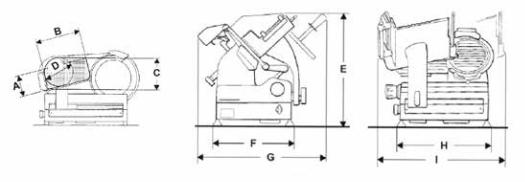
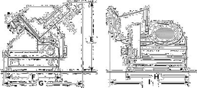
DATA SHEET
PRO LINE VS25 -VS30
MODEL |
VS25 |
|
VS30 |
|
|
|
|
E |
380 mm |
|
400 mm |
|
|
|
|
F |
300 mm |
|
300 mm |
|
|
|
|
G |
380 mm |
|
420 mm |
|
|
|
|
H |
380 mm |
|
380 mm |
|
|
|
|
I |
550 mm |
|
610 mm |
|
|
|
|
SPECIFICATIONS |
|
|
|
|
|
|
|
ø Blade |
250 mm |
|
300 mm |
|
|
|
|
Cut thickness |
0 -14 mm |
|
0 -14 mm |
|
|
|
|
Net weight |
17 kg |
|
20 kg |
|
|
|
|
Cutting capacity (rect.) |
210x120 mm |
|
210x160 mm |
|
|
|
|
Cutting capacity (circ.) |
165 mm |
|
200 mm |
|
|
|
|
Motor rating |
0,20 kW |
|
0,20 kW |
|
|
|
|
|
|
230 V - 50 Hz |
|
Specificationelectrical |
|
220 V - 60 Hz |
|
|
|
120 V 60 Hz |
|
|
|
|
|
20
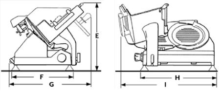
PRO LINE GL30
MODEL |
GL30 |
|
|
A |
170 mm |
|
|
B |
200 mm |
|
|
C |
225 mm |
|
|
D |
200 mm |
|
|
E |
460 mm |
|
|
F |
340 mm |
|
|
G |
530 mm |
|
|
H |
430 mm |
|
|
I |
630 mm |
|
|
SPECIFICATIONS |
|
|
|
ø Blade |
300 mm |
|
|
Cut thickness |
0 -14 mm |
|
|
Net weight |
25 kg |
|
|
Cutting capacity (rect.) |
200x170 mm |
|
|
Cutting capacity (circ.) |
200 mm |
|
|
Motor rating |
0,20 - 0,30 kW |
|
|
Specificationelectrical |
230 V 50 Hz | 220 V 60 Hz | 120 V 60 Hz |
|
|
21
PRO LINE GL30 AUTO
MODEL |
GL30 AUTO |
|
|
A |
170 mm |
|
|
B |
200 mm |
|
|
C |
225 mm |
|
|
D |
200 mm |
|
|
E |
530 mm |
|
|
F |
340 mm |
|
|
G |
550 mm |
|
|
H |
430 mm |
|
|
I |
640 mm |
|
|
SPECIFICATIONS |
|
|
|
ø Blade |
300 mm |
|
|
Cut thickness |
0 -14 mm |
|
|
Net weight |
41 kg |
|
|
Cutting capacity (rect.) |
220x170 mm |
|
|
Cutting capacity (circ.) |
200 mm |
|
|
Motor rating |
0,40 kW |
|
|
Specificationelectrical |
120 V 60 Hz - 230 V 50 Hz |
|
|
22
SLC 300 - 330 - 350
EMODEL |
SLC300 |
SLC330 |
SLC350 |
|
E |
530 mm |
530 mm |
530 mm |
|
|
|
|
|
|
F |
450 mm |
450 mm |
450 mm |
|
|
|
|
|
|
G |
650 mm |
670 mm |
670 mm |
|
|
|
|
|
|
H |
580 mm |
580 mm |
580 mm |
|
|
|
|
|
|
I |
700 mm |
740 mm |
730 mm |
|
|
|
|
|
|
SPECIFICATIONS |
|
|
|
|
|
|
|
|
|
ø Blade |
300 mm |
330 mm |
350 mm |
|
|
|
|
|
|
Cut thickness |
0 -14 |
0 -14 |
0 -14 |
|
|
|
|
|
|
Net weight |
41 kg |
43 kg |
43 kg |
|
|
|
|
|
|
Cutting capacity (rect.) |
260x150h |
280x170h |
260x190h |
|
|
|
|
|
|
Cutting capacity (circ.) |
210 mm |
240 mm |
250 mm |
|
|
|
|
|
|
Motor rating |
0,30 kW |
0,30 | 0,35 kW |
0,35 kW |
|
|
|
|
|
|
Specificationelectrical |
120/60/1 V - Hz |
120/60/1 - 230/50/1 V - Hz |
220/60/1 V - Hz |
|
230/50/1 v - Hz |
220/60/1 - 400/50/3 V - Hz |
400/50/3 V - Hz |
||
|
||||
|
|
|
|
23
SLC 350A
MODEL |
SLCX MATIC 350 |
|
|
|
|
E |
620 mm |
|
|
|
|
F |
430 mm |
|
|
|
|
G |
650 mm |
|
|
|
|
H |
570 mm |
|
|
|
|
I |
700 - 760 mm |
|
|
|
|
SPECIFICATIONS |
|
|
|
|
|
ø Blade |
350 mm |
|
|
|
|
Cut thickness |
0 -14 |
|
|
|
|
Net weight |
61 kg |
|
|
|
|
Cutting capacity (rect.) |
250x190h |
|
|
|
|
Cutting capacity (circ.) |
250 mm |
|
|
|
|
Motor rating |
0,45 kW |
|
|
|
|
Specificationelectrical |
230/50/1 V - Hz |
|
120/60/1 V - Hz |
||
|
||
|
|
24
PRO LINE XS 25 - XS 30 |
|
I |
|
B |
|
A |
|
C |
D |
|
|
|
G |
H |
E |
L |
F |
MODEL |
XS 25 |
XS 30 |
|
|
|
|
|
A |
188 mm |
215 mm |
|
|
|
|
|
B |
225 mm |
245 mm |
|
|
|
|
|
C |
178 mm |
195 mm |
|
|
|
|
|
D |
505 mm |
545 mm |
|
|
|
|
|
E |
378 mm |
415 mm |
|
|
|
|
|
F |
480 mm |
595 mm |
|
|
|
|
|
G |
445 mm |
435 mm |
|
|
|
|
|
H |
450 mm |
506 mm |
|
|
|
|
|
I |
565 mm |
640 mm |
|
|
|
|
|
L |
575 mm |
645 mm |
|
|
|
|
|
SPECIFICATIONS |
|
|
|
|
|
|
|
ø Blade |
250 mm |
300 mm |
|
|
|
|
|
Cut thickness |
0 -14 mm |
0 -14 mm |
|
|
|
|
|
Net weight |
19 kg |
26 kg |
|
|
|
|
|
Cutting capacity (rect.) |
225x178 mm |
245x195 mm |
|
|
|
|
|
Cutting capacity (circ.) |
188 mm |
230 mm |
|
|
|
|
|
Motor rating |
0,32 kW |
0,35 kW |
|
|
|
|
|
Specificationelectrical |
230/50/1 V - Hz |
230/50/1 V - Hz |
|
400/50/3 V - Hz |
|||
|
|
||
|
|
|
Note:Asweactuallystrivetoimproveourproducts,specificationsarenecessarilysubjecttochange without notice.
25

IT
MANUALE D’USO: Affettatrici elettriche Pro Line
MODELLI:
GL30, GL30AUTO, VS25,VS30, SLC 300-330-350, SLC 350A, XS 25, XS 30
7
6
2
1
12
20
19
22
Fig. 1
10 |
11 |
18
13
13b
3
5 |
|
|
16 |
|
4 |
|
|||
|
17 |
|
9 |
8 |
|
|
|
||
|
|
|
|
|
14 |
15 |
21 |
|
1a 1b 1c 1d 1e
23 |
1h |
1g 1f |
|
|
COMPONENTI
PRINCIPALI
1.Pulsante di avviamento
2.Pulsante di arresto
3.Manopola bloccaggio piatto
4.Piedino
5.Manopola regolazione spessore fetta
6.Piastra spessimetro (vela)
7.Protezione di sicurezza
8.Piatto portamerce
9.Maniglia del pressamerce
10.Lama
11.Anello di sicurezza (paralama)
12.Affilatoio
13.Manopolina coprilama
13b. Manopolina coprilama per XS
14.Parafetta
15.Basamento
16.Carrello
17.Pressamerce
18.Disco paralama
19.Cavo di alimentazione
20.Tirante coprilama
21.Oliatore barra carrello (dove presente)
GL30 AUTO
22.Pulsantiera comandi
23.Manopola sgancio carrello
1a. Impugnatura regolazione corsa
1b. Avviamento lama
1c. Led avviamento lama
1d. Led tensione rete
1e. Arresto lama
1f. Arresto piatto portamerce
1g. Led avviamento piatto portamerce
1h. Avviamento piatto portamerce
26
|
13 |
8 |
12 |
|
|
14 |
|
|
|
|

 5
5
19 |
20 |

 3
3
|
|
1 |
|
2 |
17 |
|
|
|
|
||
|
|
|
|
|
|
|
|
4 |
|
|
|
|
|
11 |
|
|
|
|
18 |
|
10 |
|
13 |
24 |
|
|
|
||
|
|
|
|
||
|
|
|
|
|
14 
15 |
21 |
7 |
|
|
|
|
6 |
|
1a |
1b 1c |
1d 1e |
|
22 |
23 |
1h |
1g 1f |
Fig. 2 |
|
|
|
|
|
|
|
|
SLC 300 - 330 - 350
SLC 350A
COMPONENTI
PRINCIPALI
1.Pulsante di avviamento
2.Pulsante di arresto
3.Manopola regolazione spessore fetta
4.Piedino
5.Maniglia spingipiatto
6.Supporto piatto
7.Manopola bloccaggio piatto
8.Piatto portamerce
10.Pressamerce
11.Coprilama (paralama)
12.Affilatoio
13.Maniglia pressamerce
14.Piastra spessimetro (vela)
15.Basamento
17.Oliatore lubrificazione guide
18.Lama
19.Tirante coprilama
20.Parafetta
21.Anello di sicurezza
24.Protezione di sicurezza piatto
SLC 350A
22.Pulsantiera comandi
23.Manopola sgancio carrello
1a. Impugnatura regolazione corsa
1b. Avviamento lama
1c. Led avviamento lama
1d. Led tensione rete
1e. Arresto lama
1f. Arresto piatto portamerce
1g. Led avviamento piatto portamerce
1h. Avviamento piatto portamerce
27

DESCRIZIONE
Macchine affettatrici professionali con lama circolare, progettate per affettare esclusivamente prodotti alimentari del tipo e nei limiti dimensionali indicati nel presente manuale. Le parti principali che compongono la macchina sono illustrate alla figura 1. Lo schema elettrico è riportato alla figura 2.
DICHIARAZIONE DI
CONFORMITÀ
Le macchine descritte in questo manuale sono conformi alle direttive 2006/42/ CE, 2006/95/CE, 2004/108/ CE, 2003/108/CE, 2011/65/ CE, al regolamento europeo (EC) 1935/2004 ed ai relativi standard quali EN 1974:1998 +A1, EN60204-1, EN60335-1, EN60335-2-64.
SICUREZZA
Per la vostra sicurezza, fate attenzione alle seguenti istruzioni: --leggere attentamente tutte le istruzioni prima di usare la macchina;
--il prodotto non è indicato per l’utilizzo da parte dei bambini; --utilizzare la macchina solo se propriamente istruiti e in perfetto stato psico-fisico;
--non usare la macchina in alcun modo differente da come indicato nel presente manuale; --installare la macchina in conformità alle istruzioni riportate al paragrafo ‘Installazione’;
--installare la macchina in luogo al di fuori della portata di personale estraneo alle operazioni relative all’impiego e soprattutto di minori;
--utilizzare la macchina con grande concentrazione, non distrarsi durante l’uso;
--evitare l’uso da parte di personale che non abbia letto e compreso a fondo il contenuto del presente manuale;
--non indossare indumenti svolazzanti o con maniche aperte; --non permettere ad alcuno, al di fuori dell’operatore, di avvicinarsi durante l’operazione di taglio del prodotto;
--non rimuovere, coprire o modificare le targhette collocate sul corpo macchina e, in caso di danneggiamento delle stesse, sostituirle prontamente;
--non rimuovere le protezioni trasparenti e non modificare o escludere le protezioni meccaniche ed elettriche;
--affettare unicamente i prodotti consentiti, non tentare prove di taglio con prodotti di tipo proibito;
--mantenere la zona di appoggio del prodotto affettato, la zona di lavoro tutt’intorno alla macchina e il piano pavimento operatore sempre puliti ed asciutti;
--non utilizzare la macchina come superficie d’appoggio e non appoggiarvi alcuno oggetto estraneo alle normali operazioni di taglio;
--non usare l’affettatrice quando, a seguito di normale usura, la distanza tra il filo della lama e l’anello para lama ha superato i 6 mm, in tal caso contattare il produttore o uno dei Centri Servizio Autorizzati per cambiare la lama;
--non impiegare la macchina con collegamenti elettrici di tipo ‘volante’, a mezzo di cavi provvisori o non isolati;
--controllare periodicamente lo stato del cavo di alimentazione e del pressacavo sul cor-
po macchina, sostituirlo prontamente. Quando necessario rivolgendosi per l’intervento a personale qualificato;
--arrestare immediatamente la macchina in caso di difetto, funzionamento anomalo, sospetto di rottura, movimenti non corretti, rumori insoliti;
--prima di eseguire la pulizia o di effettuare interventi di manutenzione scollegare la macchina dalla rete di alimentazione elettrica;
--utilizzare guanti protettivi per le operazioni di pulizia e di manutenzione;
--porre e rimuovere la merce da affettare sul piatto scorrevole solo con il carrello completamente arretrato e con la manopola regolazione spessore posizionata in sicurezza (Fig. A);
--per il movimento del piatto portamerce durante l’operazione di taglio usare esclusivamente la maniglia di manovra posta sul braccio o impugnatura del pressamerce;
--non è ammesso l’uso di accessori per il taglio che non siano stati forniti dal costruttore a corredo della macchina.
Il costruttore declina ogni responsabilità diretta ed indiretta derivante da uso inappropriato, modifiche e/o riparazioni non autorizzate effettuate sulla macchina non autorizzate, utilizzo di accessori e ricambi non originali.
La macchina non può essere impiegata in luoghi aperti e/o esposta agli agenti atmosferici e in ambienti con vapori, fumi o polveri corrosivi e/o abrasivi, con rischio di incendio o esplosione e comunque ove sia prescritto l’impiego di componenti antideflagranti.
Condizioni ambientali d’uso:
28

-Temperatura da -5°C a +40°C
-Umidità max 95%
NON AFFETTARE:
-prodotti alimentari congelati;
-prodotti alimentari surgelati;
-prodotti alimentari con ossa (carne e pesce);
-ogni altro prodotto non destinato all’uso alimentare;
-si sconsiglia il contatto dei componenti in alluminio con alimenti fortemente acidi o fortemente salati.
L’anello di sicurezza attorno alla lama è realizzato in conformità alla norma europea EN 1974:1998 +A1, tuttavia, la protezione nell’area di affilatura non elimina totalmente il rischio di taglio.
!ATTENZIONE! Durante le operazioni di pulizia lama
ed affilatura, fare estrema attenzione a tenere le mani il più lontano possibile dall’area non protetta. Si raccomanda l’uso di guanti di protezione.
INSTALLAZIONE
Installare la macchina su di un piano ben livellato, liscio, asciutto ed adatto a sostenere il peso della macchina stessa più la merce da affettare.
!AVVERTENZA: Verificare che non ci siano impe-
dimenti alla corsa del piatto ed al caricamento della merce da affettare sul piatto stesso.
La macchina deve essere installata nelle immediate vicinanze di una presa a norme CEE derivata da un impianto conforme alle normative vigenti provvisto di:
--protezione magneto-termica;
--interruttore automatico differenziale;
--impianto di messa a terra. Prima di eseguire l’allacciamento verificare che le caratteristiche della rete di alimentazione elettrica concordino con quelle indicate sulla targhetta dati della macchina.
USO DELL’AFFETTATRICE
FUNZIONAMENTO MANUALE – PER MODELLI VS25 – VS30 – GL30 - XS 25 - XS 30:
!ATTENZIONE! Lama affilata, pericolo di taglio!
Controllare che la manopola di regolazione spessore fetta (5) sia in posizione di sicurezza (in posizione 0) (Fig. A).
1.Arretrare completamente il piatto portamerce (8) verso l’o- peratore, in posizione di carico (Fig. B);
2.sollevare il pressamerce (17) e porlo in posizione di riposo;
3.appoggiare la merce da affettare sul piatto a ridosso della sponda del piatto, lato operatore. Bloccare con il pressa merce esercitando una leggera pressione;
4.regolare lo spessore della fetta. Azionare la lama (10) premendo il pulsante di accensione
(1). Impugnare la maniglia del pressamerce (9) ed iniziare il movimento alternativo di taglio;
5.al termine delle operazioni di taglio riportare in sicurezza la manopola regolazione spessore ed arretrare il carrello. Arrestare il movimento della lama premendo il pulsante di spegnimento (2).
FUNZIONAMENTO AUTOMATICO – PER IL MODELLO GL30A:
1. Ruotare in senso antiorario di 180° l’impugnatura di sgan-
cio carrello (3);
2.premere il pulsante di avviamento lama (1b);
3.premere il pulsante di avviamento piatto portamerce (1h);
4.per selezionare la corsa del carrello più idonea alle misure del prodotto da affettare, ruotare l’impugnatura di regolazione corsa carrello (1a) in senso orario per allungare e in senso opposto per accorciare (Fig. C).
!ATTENZIONE! Quando la macchina è in funzione
non avvicinare le mani al carrello o al piatto portamerce.
Terminata l’operazione di taglio, premere il pulsante di arresto del piatto portamerce (1f): la lama rimane in funzione mentre il piatto portamerce si ferma a fondo corsa lato operatore, pronto per un nuovo ciclo di taglio.
Se si preme il pulsante di arresto lama (1e), il piatto portamerce si ferma nella posizione in cui si trova.
FUNZIONAMENTO MANUALE PER SLC 300-330-350, SLC 350A: appoggiare il prodotto da affettare sul piatto contro la parete del piatto portamerce, a ridosso della sponda del piatto, lato operatore; bloccare con il pressamerce esercitando una certa pressione; nelle versioni gravità, la merce premerà contro la piastra per il proprio peso;
-- usando l’apposita manopola (3), regolare lo spessore della fetta. Azionare la lama (18) premendo il pulsante di accensione (1). Impugnare la maniglia del pressamerce (13) ed iniziare il movimento alternativo di taglio;
-- nei modelli Gravità, quando
29

il peso del prodotto o la sua di- |
PULIZIA |
mensione non permettono un |
|
|
|
taglio soddisfacente per il solo |
Mantenere una pulizia accura- |
effetto della gravità, utilizzare |
ta della macchina. Se utilizzata, |
l’impugnatura del pressamerce |
deve essere pulita almeno una |
per aiutarsi; |
volta al giorno o con maggior |
-- al termine delle operazioni |
frequenza se necessario. Dopo |
di taglio riportare in sicurezza |
un periodo di inattività si rac- |
la manopola regolazione spes- |
comanda la pulizia anche prima |
sore ed arretrare il carrello. |
dell’utilizzo. |
Arrestare il movimento della |
|
lama premendo il pulsante di |
! |
ATTENZIONE! |
Pericolo |
|||||
spegnimento (2); |
|
|
di scossa elettrica! Prima |
|||||
-- allontanare il piatto scorre- |
di procedere alla pulizia della |
|||||||
vole dal piano spessimetro e |
macchina, |
scollegare la spina |
||||||
scaricare il prodotto. |
|
della |
rete |
di |
alimentazione |
|||
|
|
|
|
elettrica e portare in sicurez- |
||||
FUNZIONAMENTO |
AUTO- |
za la manopola di regolazione |
||||||
MATICO (SOLO |
PER SLC |
spessore. |
|
|
|
|||
350A): |
|
|
|
|
|
|
|
|
1. Ruotare in senso antiorario |
! |
ATTENZIONE! |
Lama af- |
|||||
di 180° l’impugnatura di sgan- |
filata, |
pericolo |
di taglio! |
|||||
cio carrello (3); |
|
|
Controllare che la manopola di |
|||||
2. premere il pulsante di avvia- |
regolazione spessore fetta (5) |
|||||||
mento lama (1b); |
|
|
sia in posizione di sicurezza (in |
|||||
3. premere il pulsante di avvia- |
posizione 0) (Fig. A). |
|
||||||
mento piatto portamerce (1h); |
NON LAVARE NESSUN COM- |
|||||||
4. per selezionare la corsa del |
PONENTE |
IN |
LAVASTOVI- |
|||||
carrello più idonea alle misure |
GLIE! |
|
|
|
||||
del prodotto da affettare, ruo- |
|
|
|
|
|
|||
tare l’impugnatura di regolazio- |
Prodotti per la pulizia: |
|||||||
ne corsa carrello (1a) in senso |
utilizzare esclusivamente ac- |
|||||||
orario per allungare e in senso |
qua |
e detersivo |
schiumoso |
|||||
opposto per accorciare (Fig. C). |
biodegradabile |
per |
stoviglie, |
|||||
! |
ATTENZIONE! Quando la |
impiegando un panno morbido, |
||||||
macchina è |
in |
funzione |
spugnoso e uno spazzolino di |
|||||
non avvicinare le mani al car- |
nylon semirigido per le zone del |
|||||||
rello o al piatto portamerce. |
piatto e del pressamerce ap- |
|||||||
|
|
|
|
puntito. Non pulire la macchina |
||||
Terminata l’operazione di ta- |
con getti d’acqua o vapore o |
|||||||
glio, premere il pulsante di |
con metodi similari. |
|
||||||
arresto del piatto portamerce |
|
|
|
|
|
|||
(1f): la lama rimane in funzione |
Procedere alla rimozione di: |
|||||||
mentre il piatto portamerce si |
- piatto portamerce: |
|
||||||
ferma a fondo corsa lato opera- |
1) liberare il piatto portamer- |
|||||||
tore, pronto per un nuovo ciclo |
ce ruotando in senso antiora- |
|||||||
di taglio. |
|
|
riol’impugnaturadifissaggio. |
|||||
|
|
|
|
Con la manopola di regola- |
||||
Se si preme il pulsante di arre- |
zione spessore in sicurezza, |
|||||||
sto lama (1e), il piatto porta- |
arretrare il supporto piatto |
|||||||
merce si ferma nella posizione |
completamente, sino a fon- |
|||||||
in cui si trova. |
|
|
do corsa, verso l’operatore: |
|||||
uno scatto metallico avvisa l’operatore che il piatto portamerce è bloccato; 2) sfilare il pressamerce; 3) estrarre il piatto portamerce sfilando il piatto dal supporto (Fig. D);
-coprilama:
1)allentare ruotando in senso antiorario l’impugnatura tirante del disco coprilama;
2)per sollevare il disco della lama premere sull’impugnatura nella direzione della lama; 3) sollevare il disco coprilama (Fig. E);
-parafetta:
allentare la vite di fissaggio dove presente e togliere il parafetta (Fig. F).
!ATTENZIONE! Lamaaffilata,pericoloditaglio!Per le
operazioni di pulizia dell’area di affilatura,delpiatto,delpressamerce e della lama si raccomanda l’uso di guanti di protezione.
Proseguire con la pulizia di:
-lama: premere un panno umido sulla superficie della lama e spostarlo lentamente dal centro verso l’esterno, come in figura (Fig. G), sul lato corpilama e sul lato opposto. Asciugare, nello stesso modo, utilizzando un panno asciutto;
-anello di sicurezza: usare uno spazzolino di nylon semirigido per pulire l’area compresa tra la lama e l’anello di protezione;
-corpo macchina: pulire il corpo macchina con un panno umido o una spugna risciacquando acqua. Asciugare con cura.
MANUTENZIONE
Affilaturalama
Periodicità e durata dell’affilatura dipendono dall’utilizzo dell’apparecchiatura.
30
 Loading...