


Chromophare D-300
CHROMOPHARE
®
D 650plus, D 530plus, D 300, C 95x
Operating instructions
Single Light and Combination Light

CHROMOPHARE® D 650plus, D 530plus,D 300, C 95x Operating instructions (E)
CONTENTS PAGE
1. General 4 - 6
1.1 Introduction 4 - 5
1.2 Manufacturer’s notes 5
1.3 General information 6
1.4 Information about product liability 6
1.5 Incoming inspection 6
1.5.1 Permissible environment conditions for transport and storage 6
1.6 CE certification 6
2. Before Operating 7 - 9
2.1 Range of application (purpose) 7
2.2 Safety information/cautions 7
2.3 Installation instructions 8
2.4 Instructions for initial start-up 8
2.5 Visual and performance check 8
2.6 Cleaning, sterilization, disinfection 9
3. Components 10 - 13
3.1 CHROMOPHARE® C 95x/D 650plus or. D 530plus 10
3.2 CHROMOPHARE® D 650plus/650plus or. D 530plus (flat cardanic) 11
3.3 CHROMOPHARE® D 650plus/530plus or. D 530plus (classic cardanic) 11
3.4 CHROMOPHARE® D 530plus (flat cardanic) 12
3.5 CHROMOPHARE® D 530plus (classic cardanic) 12
3.6 CHROMOPHARE® D 300 (double arm) 13
3.7 CHROMOPHARE® D 300 (single arm) 13
4. Operation 14 - 21
4.1 Controll Panel CHROMOPHARE® C 95x 14
4.2 Controll Panel CHROMOPHARE® D 650plus 15 - 16
4.3 Controll Panel CHROMOPHARE® D 530plus 17
4.4 Controll Panel CHROMOPHARE® D 300 18
4.5 Notes on operation and Positioning the lights 18 - 19
4.5.1 Adjusting the field size 20
4.5.2 Adjusting the field size CHROMOPHARE® C 95x, on the control panel 20
4.5.3 Adjusting the field size with the center hand grip 20
4.5.4 Changing the sterilizable handle 20
4.6 Accessoires for CHROMOPHARE® generation 21
4.6.1 Sterilizable handles 21
4.6.2 Halogen bulb 21
4.7 System variants 21
2

CHROMOPHARE® D 650plus, D 530plus,D 300, C 95x Operating instructions (E)
CONTENTS PAGE
5. Options 22 - 25
5.1 Option for CHROMOPHARE® C 95x 22
5.2 Option for CHROMOPHARE® D generation 22
5.3 Light Pilot SystemLFN for CHROMOPHARE® C 95x 22
5.3.1 Adjusting the field size for LFN model CHROMOPHARE® C 95x 23
5.4 Autobloc System (AB) only CHROMOPHARE® C 95x 23
5.5 Light Pilot SystemLFN only for CHROMOPHARE® D 650plus 23
5.5.1 Adjusting the field size for LFN model D 650plus 24
5.6 Changing the sterilizable handles - LFN model 24
5.7 Accessoires for CHROMOPHARE® C 95x LFN and D 650plus LFN - Light Pilot 24
5.8 EndoLite
5.9 Camera system 25
6. Maintenance 25 - 30
6.1 Identification of the serial number 25
6.2 Notes on changing fuse 26
6.3 Instructions for changing lamps 26- 27
6.3.1 CHROMOPHARE® C 95x 28 - 29
6.3.2 CHROMOPHARE® D 650plus, 530plus 28 - 29
6.3.3 CHROMOPHARE® D 300 (double and single arm) 30
®
24
7. Technical data 31 - 38
7.1 CHROMOPHARE® C 95x 31 - 32
7.2 CHROMOPHARE® D 650plus 33 - 34
7.3 CHROMOPHARE® D 530plus 35 - 36
7.4 CHROMOPHARE® D 300 (double and single arm) 37
7.5 CHROMOPHARE® D 300 version 24 V (double and single arm) 38
3

CHROMOPHARE® D 650plus, D 530plus,D 300, C 95x Operating instructions (E)
1. GENERAL
1.1 Introduction
The CHROMOPHARE® D 650plus, D 530plus and C 95x, consists of a swivel arm support, a lamp housing and
a flange tube .The lamp housing is fixed to a cardanic-type support (vertical gimbal joint, horizontal gimbal joint)
and can be rotated, swiveled and tilted in any direction. The height is adjusted via the 360° rotating vertical spring
arm. The spatial position of the lamp is adjusted by means of the 360° rotating horizontal swivel arm.
The special features of the CHROMOPHARE® D generation are:
• Dents and paint scratches or chips on the light hood are eliminated. An impact-absorbent light hood made of
polymer material prevents deformations and paint defects.
• Cool light in the surgical area and in the beam path of the operating lights, which is achieved by filtering out the
infrared proportion by means of the proven ThermoSorb® double filter system.
• The newly designed suspension and the hand grip with a particularly wide protective collar and an integrated
release mechanism, ensure a high degree of hygiene.
• In the case of failure of the main lamp, 100 percent identical light ratios are guaranteed by the lamp-swivel
mechanism, which swings the reserve lamp into the position of the main lamp.
Additional special features of the CHROMOPHARE® D 650plus
• High illuminance of 130.000 lx for illuminating a deep surgical area, which is achieved with the assistance of the
newly developed polygon reflector with its mirror-like surface and “light booster”.
• Increase of the illuminance till to 150.000 lx with the assistance of the booster function.
• Excellent depth of illumination and low shadow levels, which are achieved by modifying the light beam using
reflector elements.
Additional special features of the CHROMOPHARE® D 530plus
• High illuminance of 110.000 lx for illuminating a deep surgical area, which is achieved with the assistance of the
newly developed polygon reflector with its mirror-like surface.
• Excellent depth of illumination and low shadow levels, which are achieved by modifying the light beam using
reflector elements.
4

CHROMOPHARE® D 650plus, D 530plus,D 300, C 95x Operating instructions (E)
Additional special features of the CHROMOPHARE® C 950 and C 952 are:
• Cool light in the surgical area and in the beam path of the operating lights, which is achieved by filtering out the
infrared proportion by means of the proven ThermoSorb® double filter system.
• The suspension and the hand grip ensure a high degree of hygiene.
• High illuminance of the CHROMOPHARE® C 950G till to 105.000 lx for illuminating a deep surgical area,
which is achieved with the assistance of the newly developed polygon reflector with its mirror-like surface.
• High illuminance of the CHROMOPHARE® C 952G till to 150.000 lx for illuminating a deep surgical area,
which is achieved with the assistance of the newly developed polygon reflector with its mirror-like surface.
Increased intensity via clear light emission surface
• Excellent depth of illumination and low shadow levels, which are achieved by modifying the light beam using
reflector elements.
1.2 Manufacturer´s notes
The manufacturer of the products specified in the user’s manual is:
BERCHTOLD GmbH & Co. KG
Ludwigstaler Straße 25
Postfach 4052
D-78505 Tuttlingen
Internet: www.BERCHTOLD.de
e-mail: Info@BERCHTOLD.de
Tel. (+49) 7461 / 181-0
Fax (+49) 7461 / 181-200
5

CHROMOPHARE® D 650plus, D 530plus,D 300, C 95x Operating instructions (E)
1.3 General information
• This user’s manual is considered part of the equipment. It must be kept in the vicinity of the equipment at all
times. Precise observance of the user’s manual is a prerequisite for the proper use and correct operation of the
equipment, which is essential for the safety of patients and operators alike.
• Only accessories which are specified in this user’s manual, and which have been tested together with the equipment, may be used. If accessories are used which are not specified in the user’s manual, their ability to be used in
accordance with safety regulations must be proved.
• All literature relates to the equipment model and the prevailing basic safety regulations when printed. All rights
are reserved for equipment, switches, procedures, software programs and names.
1.4 Information about product liability
BERCHTOLD considers itself responsible for the consequences of safety, reliability and performance of the
equipment only if
a) installation, modifications or repairs have been performed only by BERCHTOLD, or by an agent expressly
authorized by BERCHTOLD to do so,
b) the electrical installation of the room complies with regulations IEC 60364-7-10,
c) the equipment is used in accordance with the user’s manual.
1.5 Receiving inspection
Please inspect the equipment and accessories immediately after receipt for any transportation damage and defects.
Claims for damage will only be valid if the vendor (BERCHTOLD) or the carrier are informed
at once. A damage report must then be prepared immediately. The damage record must be submitted to the nearest BERCHTOLD representative or to BERCHTOLD directly.
When an appliance or parts of an appliance are returned to BERCHTOLD or to a BERCHTOLD service agent,
the original packaging should be used where possible. The following accompanying documentation must be attached: owner’s name and address, equipment number (see type plate), description of the defect.
1.5.1
For transport and storage (in original packing, ; for maximum 15 weeks)
Ambient temperature - between –10°C and +60°C
Relative air moisture - between 10 % and 85 %, no condensation
Air pressure - between 500 hPa and 1060 hPa
For operation
Ambient temperature - between +10°C and +40°C
Relative air moisture - between 30 % and 75 %
Air pressure - between 700 hPa and 1060 hPa
1.6 EC Certification
The equipment complies with the requirements of the EC guideline regarding medical products, 93/42/EEC as
well as the UL guidlines.
6

CHROMOPHARE® D 650plus, D 530plus,D 300, C 95x Operating instructions (E)
2. BEFORE OPERATING
2.1 Range of application (purpose)
The CHROMOPHARE® light is a medical light for use in hospital treatment rooms. It is used for the local illumination of the patient’s body, so that illnesses, injuries and handicaps can be recognized and treated. It may only
be used in rooms which have been correctly designed out in accordance with IEC 60364-7-10.
The CHROMOPHARE® light as a single light provides a very high degree of failure protection, as it is equipped
with automatic switch-over to a reserve lamp, electronic monitoring with a “bypass switch” and an automatic APU
switch-over. However, not all components are duplicated, so that in some circumstances a failure is still possible.
As a matter of principle, single lights should not be used for operations where a light failure could represent a
great danger to the patient.
Light combinations with two or even three light heads provide more security against light failure and a better
brightness of the operating field. They provide light from different angles and maximum protection against light
failure due to the fact that all components exist twice. This applies particularly when they are connected to an
emergency power supply (APU) in addition to the mains supply. These combination lights may be used in all
medical disciplines for the illumination of surgical areas.
2.2 Safety informations / cautions
• Incorrect operation and non-observance of safety measures can cause serious incidents. Therefore make sure
that you have read and understood the information in your CHROMOPHARE® user’s manual.
• The light is not intended for operation in areas where there is danger of explosion.
• Do not look into the switched-on light from the front and do not put any reflective objects into the path of the
beam. Because of the high illumination strength there is a danger of glare.
• The distance between the light emission surface area of the operating light and the patient surface should not be
less than 60 cm in order to ensure proper illumination.
• The light must not be operated if the cover glass or the filter system is damaged or destroyed. Thermal radiation
can reach the surgical area, heating up and drying out the tissue of the operation wound. If the effect is prolonged, there is even the danger of tissue necrosis.
• Do not place any objects on the lamp housing or hang objects on arms or lamp housings, as this may compromise the stability of the fixing and there is the danger that these objects may fall into the surgical area. Attaching
or hanging heavy objects can destroy the mechanism.
• The lamp housing must not be covered while in operation, as this prevents heat exchange with the environment
and could cause the surgical light to overheat.
• Collision of the supporting arms and lamp housings should to be avoided. A severe collision could result in
lights being damaged or parts knocked off and falling into the surgical area.
• The overlay of the light fields can cause an increase in heat generation
7

CHROMOPHARE® D 650plus, D 530plus,D 300, C 95x Operating instructions (E)
2.3 Installation instructions
Mounting and installation of the CHROMOPHARE® lights must be in accordance with BERCHTOLD’s
“Mounting instructions for ceiling lights” and must only be performed by BERCHTOLD employees or by installation companies authorized by BERCHTOLD. The installation of lights on the ceiling of the operating room
must be performed in accordance with BERCHTOLD’s “Ceiling anchor plate and spacer block” mounting instructions due to weight and high torque.
Incorrect assembly of the lights can result in ceiling anchorage damage off and falling down, critically injuring the
patient and operating staff in the process. The on-site electric installation must be performed in accordance with
IEC 60364-710 and include a fuse protection as well as a mains switch for a simultaneous all-polo separation of
the light. For further information, please note the mounting instructions.
2.4 Instructions for initial start-up
The operator may begin to use the light, after the manufacturer or supplier:
a) Has carried out a performance check at the place of operation,
b) has introduced those responsible for the operation of the light to its correct handling by means of the user’s
manual.
2.5 Visual and performance check
Before initial start-up the manufacturer or supplier should check that the CHROMOPHARE® light has been
properly installed and is in a safe and operational condition.
A visual inspection of the following points must take place:
• After switching-on the unit, light must be emitted from the main lamp, and in the case of combination lights,
also from the additional lamp.
• Inspection of the light emission lens of the lamp housing.
If the light emission lens is damaged or broken, glass splinters can fall out. The light must be switched off immediately and must not be used until the defect has been rectified.
• Inspection of the reserve lamp warning indicator CHROMOPHARE® C 95x
In the case of failure of the main lamp, the reserve lamp is automatically switched on: The red warning indicator
on the keyboard illuminates to indicate this error. The defective main lamp must be replaced immediately.
• Inspection of the reserve lamp warning indicator CHROMOPHARE® D Generation
In the case of failure of the main lamp, the reserve lamp is automatically switched on and swung into the position of the main lamp. The yellow warning indicator on the lamp housing illuminates to indicate this error. The
defective main lamp must be replaced immediately.
• Checking the operational state of the control unit.
The individual functions must be checked by activating the appropriate keys. Faults in the main circuit of the
control electronics of the CHROMOPHARE® D 650 and D 530 are indicated by the red fault indicator on the
control unit. In this case the light operates at its maximum luminous intensity and can no longer be controlled
via the keys.
• Checking the movement mechanism for perfect operation.
The mechanical operation of the lightsystem is checked by swiveling and rotating the movement mechanism.
8

CHROMOPHARE® D 650plus, D 530plus,D 300, C 95x Operating instructions (E)
2.6 Cleaning, sterilization, disinfection
• All parts of the CHROMOPHARE® light can be cleaned with standard commercial cleaners on all exterior surfaces including the control unit, and disinfected with the disinfectants normally used in surqical areas.
• Only disinfectants may be used, which are certified from the manufacturer at the following materials:
Polycarbonat (PC), Poliamid (PA), Polyvenylclorid (PVC), Acrylnitril-Butadien-Styrol-Copolymer (ABS),
Polyetherimid (PEI) and on Silicons.
• Cleaning, disinfectant and sterilization of the sterilizable handles.
The sterilizable handles are made of heat-proof, impact-resistant plastic (PEI). They
can be cleaned with mild alkaline cleaners without active chlorine. The cleaners must be thoroughly rinsed off
with water. Alternatively, the hand-grip holders can be cleaned mechanically with heat-sterilisation up to a
maximum temperature of 93°C/10 min.
For disinfecting the handle sleeves we recommend products with an alcohol or aldehyde base. The sleeves must
be rinsed before sterilization.
The handles can be sterilized in steam. The recommended parameters are:
1. Steam sterilization at 121° C; 1.3 bar; 25 to 30 minutes
2. Steam sterilization at 134° C; 2.3 bar; 4 minutes
When filling the autoclave ensure that the open side of the handles are face down. The sleeves must lie free and
must not come into contact with any other items being sterilized.
Hot-air sterilization is not recommended by BERCHTOLD. However, if it is necessary, the handles should be
sterilized loose at 134° C; 3 minutes.
•
Note:
Sterilizable handles are subject to natural wear. As a rule, a life of approx. 100 cleaning cycles is normal.
Damaged grip sleeves must not continue to be used.
The operator has to pay attention of the national Gremium for hygiene and desinfektion.
9
CHROMOPHARE® D 650plus, D 530plus,D 300, C 95x Operating instructions (E)
3. COMPONENTS
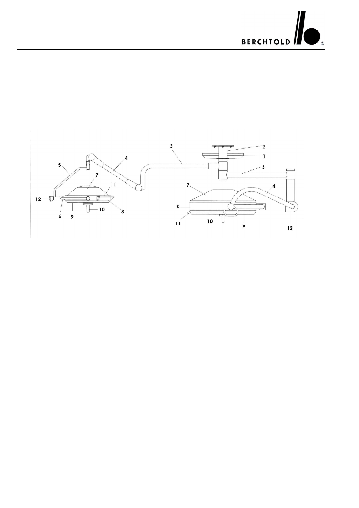
3.1 CHROMOPHARE® C 95x/D 650plus or C 95x/D 530plus
1 Ceiling cover 7 Lamp housing hood
2
Flange tube ∅125 mm
3 Horizontal swivel arm 9 Light emission lens
4 Vertical spring arm 10 Sterilizable handle
5 Vertical gimbal joint 11 Rail (encircling hand grip)
6 Horizontal gimbal joint 12 Control panel
8 Lamp frame
10
CHROMOPHARE® D 650plus, D 530plus,D 300, C 95x Operating instructions (E)
3.2 CHROMOPHARE® D 650plus/650plus or D 530plus (flat cardanic)
1 Ceiling cover 7 Lamp frame
2
Flange tube ∅125 mm
3 Horizontal swivel arm 9 Sterilizable handle
4 Vertical spring arm 10 Rail (encircling hand grip)
5 Cardan joint 11 Control panel
6 Lamp housing hood
8 Light emission lens
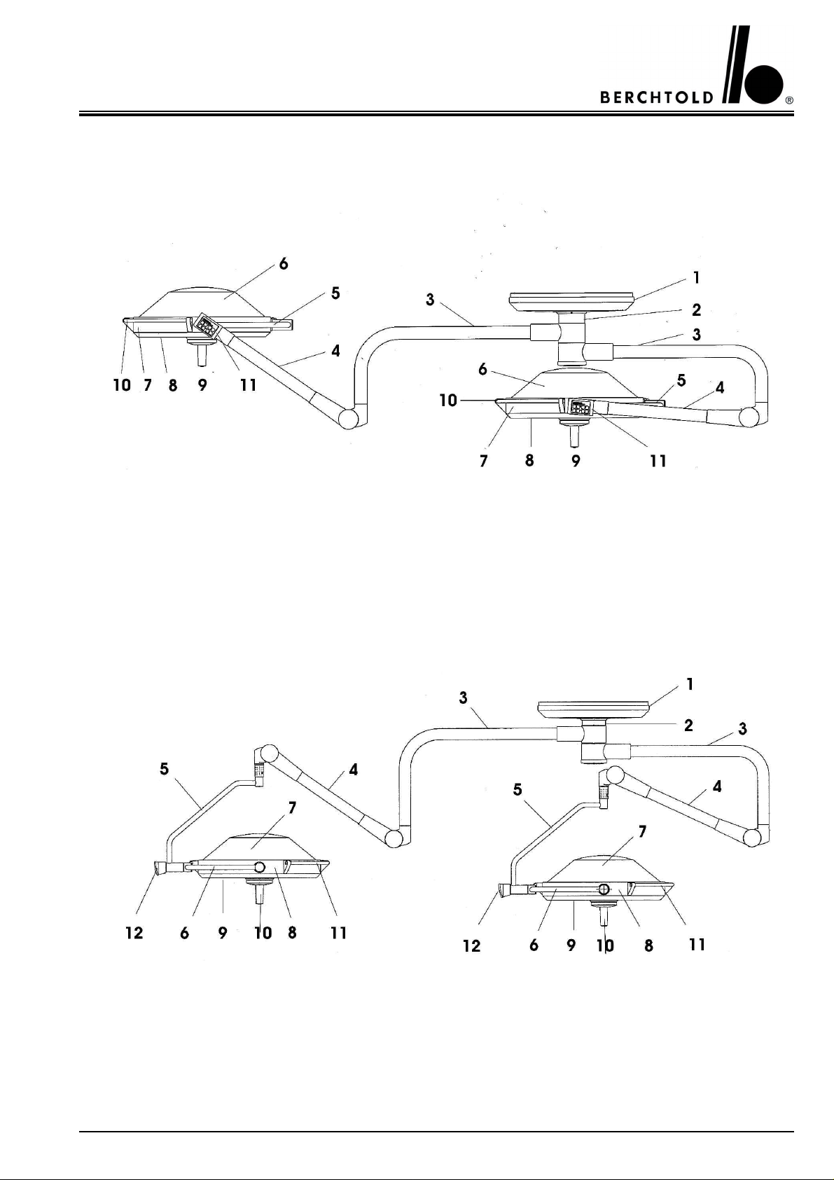
3.3 CHROMOPHARE® D 650plus/650plus or D 530plus (classic cardanic)
1 Ceiling cover 7 Lamp housing hood
2
Flange tube ∅125 mm
3 Horizontal swivel arm 9 Light emission lens
4 Vertical spring arm 10 Sterilizable handle
5 Vertical gimbal joint 11 Rail (encircling hand grip)
6 Horizontal gimbal joint 12 Control panel
8 Lamp frame
11
CHROMOPHARE® D 650plus, D 530plus,D 300, C 95x Operating instructions (E)
3.4 CHROMOPHARE® D 530plus (flat cardanic)
3.5 CHROMOPHARE® D 530plus (classic cardanic)
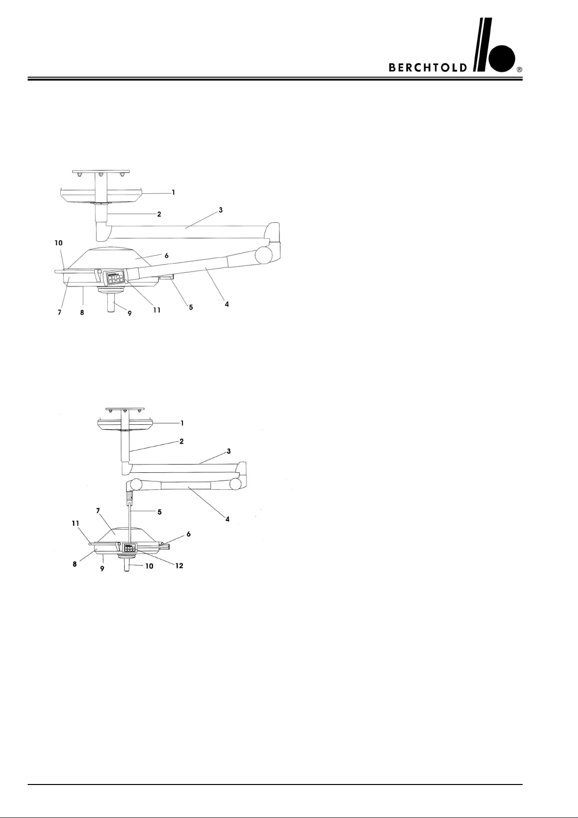
1 Ceiling cover
2 Flange tube 65 mm ø
3 Horizontal swivel arm
4 Vertical spring arm
5 Horizontal gimbal joint
6 Lamp housing hood
7 Lamp frame
8 Light emission lens
9 Sterilizable handle
10 Rail (encircling hand grip)
11 Control panel
1 Ceiling cover
2 Flange tube 65 mm ø
3 Horizontal swivel arm
4 Vertical spring arm
5 Vertical gimbal joint
6 Horizontal gimbal joint
7 Lamp housing hood
8 Lamp frame
9 Light emission lens
10 Sterilizable handle
11 Rail (encircling hand grip)
12 Control panel
12
 Loading...