

Page 1
ADRE Sxp and 408 DSPi
Datasheet
Bently Nevada Machinery Condition Monitoring
Description
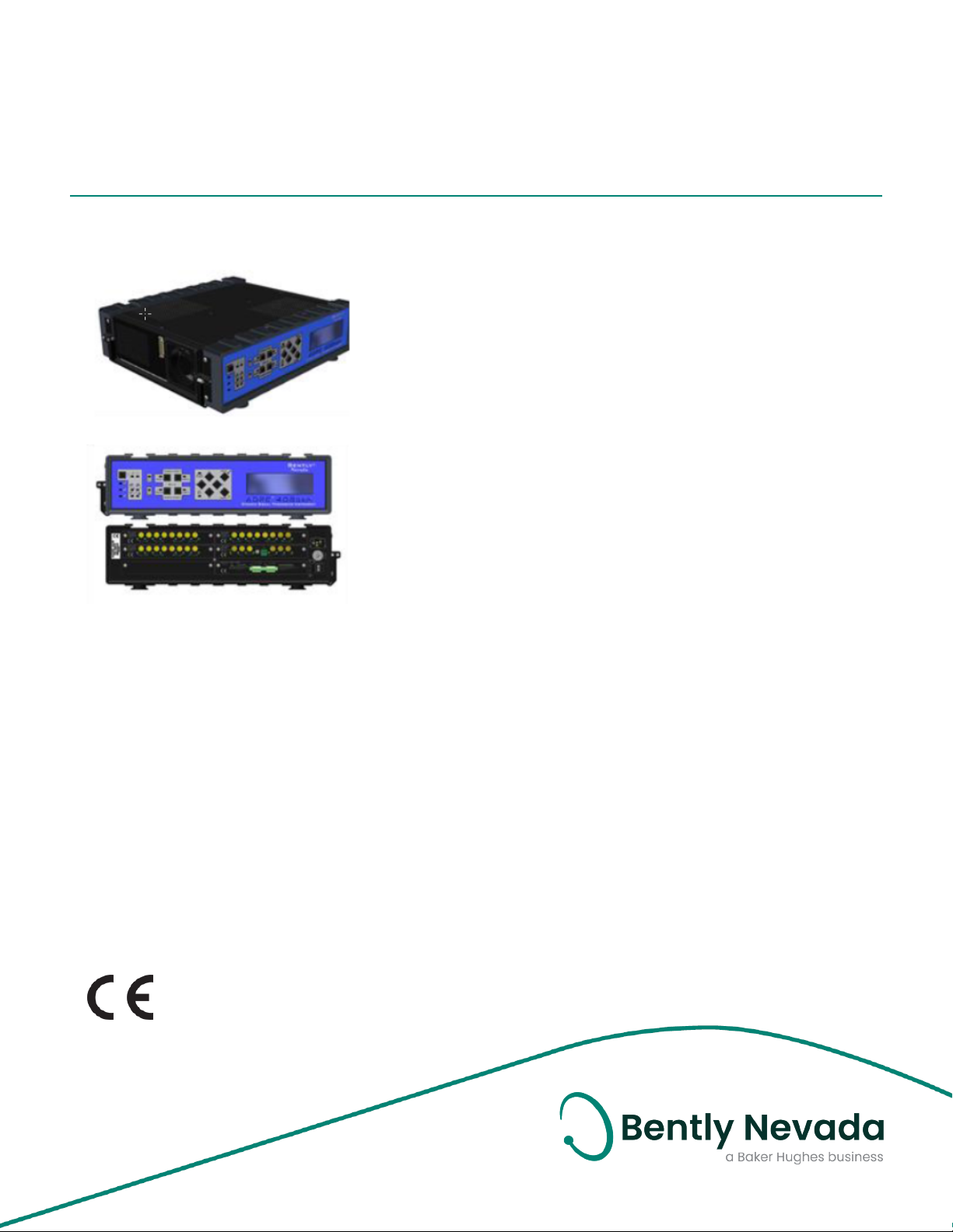
ADRE Sxp Software and the 408 DSPi (Dynamic Signal
Processing Instrument) make up a highly scalable system for
multi-channel signal processing and data acquisition.
Unlike other general-purpose computer-based data
acquisition systems, ADRE Sxp and the 408 DSPi are
specifically designed for real-time highly parallel signal
processing and presentation. This extremely versatile system
incorporates the functionality of many types of
instrumentation, such as oscilloscopes, spectrum analyzers,
filters, signal conditioners, and digital recorders into a single
platform. The system is designed specifically for secure
corporate network environments, allowing it to operate
remotely across a LAN/WAN, or store data in full “standalone” mode without an additional/external computer.
Additional equipment is seldom, if ever, needed. The system’s
real-time display capability permits it to continuously display
data independently of data being stored to permanent
memory. For established ADRE system users, ADRE Sxp also
supports all previous ADRE for Windows databases.
172179 Rev. AC
An ADRE Sxp data acquisition system consists of:
l 408 Dynamic Signal Processing Instrument(s).
l ADRE Sxp client software, ADRE Quick Configuration
software.
l A computer system capable of running ADRE Sxp
software.
The 408 DSPi is fully portable or can be rack mounted allowing
convenient operation in test stands, on-site, or at remote
locations. The 408 DSPi’s highly configurable design supports
virtually all standard and non-standard input types including
both dynamic transducer signals (such as those from
proximity probes, velocity transducers, accelerometers, force
Page 2

ADRE Sxp and 408 DSPi
Datasheet 172179 Rev. AC
hammers, dynamic pressure sensors), and
static signals (such as process variables from
transmitters and distributed control systems).
For rotating machinery applications, users can
provide a Keyphasor or other speed input
signal (such as that from a magnetic or optical
transducer) to drive synchronous sampling
and order tracking. For structural analysis
needs, impact testing using force hammers is
supported. The system also supports multiple
triggering modes for automated data
acquisition, allowing you to use the system as
a data or event logger without an operator
present.
The Client-Server architecture allows multiple
software clients to operate and simultaneously
view data from single/multiple 408 DSPi
systems simultaneously, permitting users to
independently view data in the fundamental
measurement units of their choice. Software
installation and configuration are quick and
easy, allowing mass configuration of multiple
channels with minimal user intervention.
Configuration templates and software further
simplifies the process, allowing the user to
install the software, produce a configuration,
and begin capturing data in minutes.
408 DSPi Overview
Each 408 DSPi supports up to 4 sampling cards
for up to 32 channels of data acquisition. The
408 DSPi base system uses internal clocks and
simulated speed/Keyphasor signals to support
both asynchronous and synchronous
sampling for all channels. Speed Input/Trigger
cards support up to 3 independent speed input
channels for external speed inputs. Each Speed
Input/Trigger card uses 1 available slot, and the
408 DSPi can use a maximum of 2 Speed
Input/Trigger cards simultaneously providing
up to 6 physical speed inputs and 6 simulated
speed inputs. The user can assign any speed
input (KPH) to any channel in a 408 DSPi. Most
signal processing and sampling parameters
can be changed “on-the-fly” without
interrupting data collection.
The 408 DSPi architecture provides flexible
hardware configuration. Users can insert
sampling cards into the chassis as required.
Slots 1 through 4 support all standard sampling
cards. Slot 5 is intended specifically for the
Digital Replay card as well as future option
cards.
The standard Dynamic Sampling and Speed
Input/Trigger cards provide full support for
structural analysis and impact testing. Data
can be analyzed natively or exported to 3rd
party applications if desired.
The 408 DSPi front panel controls and displays
basic functions and data. Users can directly
initiate manual samples and triggering from
the front panel without using ADRE Sxp
software. The front panel LEDs indicates
sampling and trigger status and activity. Users
can download multiple sampling
configurations to the 408 DSPi and later select
them for use from the front panel.
8-Channel Dynamic Sampling
Card (168905 – AA)
The 8-channel dynamic sampling card is an
extremely powerful and flexible signal
processing engine. Along with the analog
front-end conditioning, the user can configure
most transducer inputs, with positive or
negative bias, while maintaining maximum
signal input range. An array of DSP processors
and 24-bit ADCs provide maximum resolution.
Input signals can be either AC or DC coupled,
and users can independently define upper and
lower input voltage levels along with full-scale
range and transducer scale factor.
The sampling card can provide a variety of
data depending on the configuration and user
needs. Each channel can provide multiple
“static” variables including:
l Direct amplitude.
l Bandpass amplitude.
l 1X and 2X Amplitude and Phase, and up
to 4 additional user defined nX vectors
including amplitude and phase.
l Average & instantaneous gap or bias
voltages.
l Multiple speed values.
l Adate/time stamp.
2/33
Page 3

ADRE Sxp and 408 DSPi
Datasheet 172179 Rev. AC
In addition to the static data, each channel can
provide up to 4 user-defined dynamic
waveforms. Users can configure waveforms for
simultaneous Synchronous and/or
Asynchronous sampling, with different
sampling rates and/or frequency spans. The
sampling card supports up to 2 different
synchronous sampling rates simultaneously.
Time-Synchronous Averaging can also be
enabled for all synchronous waveforms. In
addition, the card can also sample and store
the raw time-continuous data for each
channel. All channels within the system are
always sampled simultaneously, are
synchronized, and are initiated based on a set
of user defined events.
3-Ch Speed Input/Trigger Card
(168906 – AA)
The 3-channel speed input/trigger card
supports a variety of transducer inputs and
signal conditioning needs including; proximity,
magnetic, optical, and laser pickups.
Transducer power for both optical pickup and ±
24Vdc proximity is also available if needed. For
impact testing applications, the force hammer
output can be connected directly to this card
providing level triggering and full dynamic
waveform capture. The card integrates a rich
set of configurable analog signal conditioning
tools including: input gain, voltage clamping,
inversion, rising or falling edge trigger,
auto/manual threshold, and hysteresis. The
user can associate a programmable speed
input (Keyphasor) multiplier/divider for each
channel independently, define discrete values
for events per revolution, or, a final ratio,
whichever is more convenient. Each channel
can have up to three separate “stages” of
multiplier/divider ratios. Trigger/speed input
channels provide full dynamic sampling,
complete with static and waveform data,
available for real-time viewing and storage.
Each channel also includes a buffered output,
allowing the user to select either raw,
conditioned analog, or TTL outputs. The
buffered outputs are independent of the signal
being used for processing.
Digital Replay Card
(168907 – AA – BB - CC)
The Digital Replay Card provides simultaneous
synchronous and asynchronous internal
digital reprocessing and playback of all
channels in the 408DSPi. The replay card
maintains exceptional accuracy and precision
in the signal reprocessing that far surpasses
the capabilities of other equipment and
reprocessing techniques. The digital replay
card can play back raw data for all channels
simultaneously including Keyphasor/speed
and dynamic sampler inputs. Users can modify
all sampling parameters on a KPH channel
when replayed, and fully manage and recondition the gain, inversion, clamping, and
other characteristics of Keyphasor signals. This
provides the ability to control triggering edges
and thresholds as reprocessing and analysis
requires. On standard dynamic channels, users
can modify most sampling parameters. As an
example, users may add or modify waveform
assignments, variable generation, filtering
options, frequency span, and Keyphasor
assignments that did not exist in the original
configuration reprocessing the data.
Additionally, users may add or modify all
sampling criteria and triggering parameters.
Full scale range, coupling, and transducer type
cannot be altered for standard dynamic
channels. The Digital Replay card occupies Slot
#5 of the 408 DSPi and does not reduce the
number of channels available for data
collection.
With the addition of Analog Output Replay Card
the user may send up to 32 channels of
recorded signals through data ports to
auxiliary equipment. These signals are analog
recreations of the original data observed by
ADRE. The Replay Module can be ordered with or
without the Analog Output Replay Card.
Existing Replay Cards can be modified to
include the Analog Output feature by sending
the cards to Product Repair at Bently Nevada.
3/33
Page 4

ADRE Sxp and 408 DSPi
Datasheet 172179 Rev. AC
Transducer Power Supply Card
(168908 – AA – BB)
The transducer power supply card provides
power for a wide variety of displacement,
velocity, acceleration including ICP accels, force
hammers, and other transducer types used in
field and test stand applications. This card can
simultaneously power up to 32 transducers in
various combinations, and provides direct
physical connections for up to 16 transducers,
eight ± 24 Vdc transducer systems and eight
constant current transducer systems. Field
connection cable and adapter accessories
accommodate additional transducer
connections.
In addition to ± 24 Vdc selections, the card
provides ± positive and negative bias selections
for constant current applications, all of which
can be used simultaneously, to provide a
highly flexible power source for most any need.
Users can configure transducer power bias in
blocks of four (4) directly from the card without
the need for special tools, jumpers, or software.
Networking Overview
The 408 DSPi is a secure network appliance that
supports DHCP or fixed IP addressing based on
your network environment needs. When
installed on a LAN/WAN in DHCP mode, the
DHCP server or router will assign an IP address
to the 408 DSPi. When the user makes a direct
connection between the 408 DSPi and client
computer in DHCP mode, an IP address will be
automatically assigned. The 408 DSPi also
supports fixed IP addressing. The user can
assign a fixed IP address on one Ethernet port
while simultaneously running DHCP on the
second Ethernet port. In some instances,
primarily when navigating corporate security
infrastructures, firewalls, or VPNs (Virtual Private
Networks), specific router configuration may be
necessary. Contact your local product support
representative for details specific to your needs.
Each output provides individual short-circuit
protection, current regulation, and indicators
for power status and voltage/current selection
(complete card status is provided within ADRE
Sxp client software). Also, this card can occupy
a dedicated option slot and leave all
transducer input slots available.
Field wiring cable accessories allow the user to
conveniently connect both power and signals
to the 408DSPi. These accessories support most
voltage and constant current transducer
applications without the need for additional
bulky equipment. Field wiring accessories and
cables must be ordered separately.
4/33
Page 5
ADRE Sxp and 408 DSPi
Datasheet 172179 Rev. AC
Specifications
408 DSPi
Typical specifications are provided for
a temperature of +25 °C ± 3 °C (+77 °F
± 5.4 °F ) except where noted.
Data Storage
Capacity
Communication Dual 1000/100Mb RJ45
Internal Cloc Battery-Backed Real-Time
Signal Conditioning - General
Internal - 480GB or 960GB
Ethernet Ports
Protocol - TCP/IP
DHCP or Fixed IP addressing
LAN/WAN compatible
clock (RTC) accuracy is ± 2
seconds / month
DC
0.35 to 50 V
Configurable
Full Scale
Range
Status
Indication
Boot, Selftest, OK/Not OK,
Activity, A/D over range
Direct Measurement Accuracy
Filter values @ 0 db points unless
specified otherwise.
2
Dynamic Sampling Card Amplitude
vs. Frequency Cumulative Error
Non-RMS, Non-Integrated Amplitude
AC Coupled
–
Hi Mode
AC Coupled
- Low Mode
1.6 Hz to 50 kHz
± 1.25% of Full Scale Range
N/A
2
8 Channel Dynamic Sampling Card
Slot Position Slots 1 through 4
24 Bit A/D converters
Input Impedance
Single Ended 742kΩ
Differential 1.484 MΩ between sig+ and sig-
4-20 mA 511Ω
Inputs
Single-
8
ended
Differential 4
4-20 mA 8
Maximum
-25 to 25 V
Signal Input
Range:
AC
0.7 to 10 V
Configurable
Full Scale
Range
DC Coupled
–
Hi Mode
DC Coupled
- Low Mode
1 Hz to 50 kHz
± 1% of Full Scale Range
± .011V below 1 V pp
0.167 Hz to 20 kHz
± 1% of Full Scale Range
± .011V below 1 V pp
Non-Integrated, RMS Amplitude
Acceleration
AC/DC
10 Hz to 50 kHz
± 1% of Full Scale Range
Coupled Hi
Mode
Velocity
AC/DC
Coupled Hi
10 Hz to 50 kHz
± 1% of Full Scale Range
Mode
AC Coupled
N/A
Low Mode
Acceleration 3 Hz to 50 kHz
± 1% of Full Scale Range
2
2
2
2
2
5/33
Page 6

ADRE Sxp and 408 DSPi
Datasheet 172179 Rev. AC
DC Coupled
Low Mode
Velocity DC
Coupled
Low Mode
3 Hz to 50 kHz
(-3db @ 3Hz )
± 1% of Full Scale Range
2
Non-RMS Integrated, RMS Integrated
Amplitude
Acceleration
AC Coupled
10 Hz to 20 kHz
± 1% of Full Scale Range
2
Hi Mode
Velocity AC
Coupled Hi
3 Hz to 20 kHz
± 1% of Full Scale Range
2
Mode
Direct Measurement Update Rates
Valid KPH or
Simulated
0 to Peak / Peak to Peak values
updated every 4 KPH periods.
KPH present
Invalid KPH
or No KPH
present
High Mode – 2 sec sliding
window
Low Mode – 12 sec sliding
window
100ms update rate
Integrated
Values
High Mode – 2 sec sliding
window
Low Mode – 2 sec sliding
window
100ms update rate
Bandpass Measurement Accuracy
Bandpass Filter Selections (Typical)
Butterworth 2 Pole ( -40 db/decade )
4 Pole ( -80 db/decade )
6 Pole ( -120 db/decade )
8 Pole ( -160 db/decade )
Range High Pass 1 Hz to 25.5kHz
Low Pass 10 Hz to 50kHz
Min separation between
HPF and LPF 2 Pole – 10.24 x HPF
4 Pole - 3.24 x HPF
6 Pole - 2.25 x HPF
8 Pole – 1.96 x HPF
Options HPF < 10 Hz ( 2 Pole )
HPF ≥ 10 Hz ( 2, 4, 6, 8 Pole)
LPF ≥ 10 Hz ( 2, 4, 6, 8 Pole)
-3db Corner
Frequencies
HPF & LPF - 1 Hz Increments,
-3db ± 5%
Bandpass Measurement Update Rates
Valid KPH or
Simulated KPH
present
Invalid KPH or
0 to Peak / Peak to Peak
values updated every 4 KPH
periods.
100ms update rate
No KPH
present
Integrated 2 sec sliding window
Non-
2 sec sliding window
Integrated
Filtered Measurements
Specifications are exclusive of filter
corner settings and transition regions.
Filter values specified @ -3 db points.
Non-RMS,
NonIntegrated
Amplitude
Non-RMS
Integrated,
RMS
Integrated
Amplitude
1 Hz to 50 kHz
± 1% of Full Scale Input
1 Hz to 20 kHz
± 1% of Full Scale Input
Filter
Bandwidth
Selectable
1.2 cpm, 12 cpm, 120 cpm
(0.02 Hz, 0.2 Hz, 2 Hz)
User enabled
2
Autoswitching
tracking filters
120 cpm < to > 12 cpm @ 600
rpm
12 cpm < to > 1.2 cpm @ 60
rpm
transition
2
Filter Settling
Time to 95 / 99
% of final value
6/33
120 cpm < 0.477 / .796 sec
12 cpm < 4.77 / 7.96 sec
1.2 cpm < 47.7 / 79.6 sec
Page 7

ADRE Sxp and 408 DSPi
Datasheet 172179 Rev. AC
nX Amplitude
and Phase
Accuracy
nX Resolution
and Range
1 to 120k rpm
± 1% of Full Scale Range
2
± 3˚ of Input (Steady State)
0.01X Increments
0.01X to ((sample/rev)/2-1)X
Below Minimum Amplitude
DC Coupled ≤ 0.015 Vpp
AC Coupled ≤ 0.5% of full scale
Gap Voltage Measurements
Measurement
Ranges
0 V to 24 Vdc
-24 V to 0 Vdc
-12 to 12 Vdc
-24 to 24 Vdc
Upper and Lower voltage
range fully programmable
between -25 to 25 Vdc
Amplitude ± 0.17% of FSR @ -25 to 25 V
± 0.26% of FSR @ 0 to ± 25 V
± 0.26% of FSR @ -12.5 to 12.5 V
(FSR = Full Scale Range)
Resolution Measured 366.2 µV @ 24 V
FSR
Response to 95%/99% of Final Value
Instantaneous
Gap
0.95 / 1.59 sec.
-3db ± 5% @ 0.5 Hz
61.035 µV ( 1 to 5 Vdc )
Response to
0.95 / 1.59 sec.
95%/99% of
Final Value
Low-pass filter -3db ± 5% @ 0.5 Hz
4 – 20 mA Input
Input Range 0 - 41.6 mA max
Amplitude ±1% of Full Scale Input
Resolution 244 nA / bit
Response to
5.3 / 8.84 sec
95%/99% of
Final Value
Low-pass filter -3db ± 5% @.09 Hz
Dynamic
Waveform
Data
Filtering associated with
asynchronously sampled
dynamic waveform data
specific to anti-alias filters.
Synchronously sampled
waveform data is not antialias filtered.
Asynchronous
Sampling
Rates
128 to 128kHz ( 2.56 x
Frequency Span, 50, 100, 250,
500, 1k, 2.5k, 5k, 10k, 25k, 50k Hz
)
Anti-Alias -80 db Minimum
Average Gap 5.3 / 8.84 sec,
-3db ± 5% @ .09 Hz
Process Variable Measurements
Voltage Inputs 0 to 10 Vdc( Typical )
1 to 5 Vdc Typical )
Measurement
Range
-25 to 25 Vdc ( Upper and
Lower voltage range fully
programmable)
Amplitude ± 0.12% of FSR @ 25V
± 0.30% of FSR @ 10V
± 0.75% of FSR @ 1-5V
(FSR = Full Scale Range)
Resolution 152.588 µV ( 0 to 10 Vdc )
AC Coupled 1 Hz to 50 kHz
Amplitude ±1% of Full Scale Range
Phase ±3˚ of Input
DC Coupled DC Hz to 50 kHz
Amplitude ±1% of Full Scale Range
Phase ±3˚ of Input
Output Up to 4 simultaneous
asynchronous waveforms
per channel
Synchronous
Sampling
7/33
Samples/rev (16, 32, 64, 128,
256, 360, 512, 720, 1024, 2048)
2
2
Page 8
ADRE Sxp and 408 DSPi
Datasheet 172179 Rev. AC
Rates Synch sample rate X rpm ≤
32 kHz
Hardware
Generated
Time
Synchronous
Averaging
DC Frequency
Support
Output Up to 2 simultaneous
Up to 2048 samples per
waveform, up to 512 Averages
i.e. (8 revs @ 256
samples/rev),
(4 revs @ 512 samples/rev)
937 rpm (15.62Hz) @ 2048x
1.87k rpm (31.25Hz) @ 1024x
2.66k rpm (44.4Hz) @ 720x
3.75k rpm (62.5Hz) @ 512x
5.3k rpm (88.8Hz) @ 360x
7.5k rpm (125Hz) @ 256x
15k rpm (250Hz) @ 128x
30k rpm (500Hz) @ 64x
60k rpm (1kHz) @ 32x
120k rpm (2kHz) @ 16x
(AC Frequency support from
1 Hz)
synchronous waveforms per
channel
Amplitude
error vs.
frequency
Phase error vs.
frequency
0 % from 0 to 10kHz
(± 4) % from 10kHz to 50kHz
(-0.5) to (-2.8) deg from 0 to
5kHz
(-2.8) to (-6.6) deg from 5kHz
to 10kHz
Frequency dependent
amplitude and phase
errors added to fixed
range specifications.
Keyphasor /Speed Measurements:
3 Channel Speed Input (KPH) / Trigger
Dynamic Sampling Card
Slot Position Slots 1 through 4
Accuracy 1 – 120k rpm, (+/- 0.00915)%
of Period Input, (+/- 11) rpm
@ 120k rpm Input
Hardware Generated Spectra
Spectral Lines 6400, 3200, 1600, 800, 400, 200,
100 lines, selectable. One
asynchronous spectrum per
channel.
Windowing provided on
spectrum up to 800 lines,
Rectangular, Hanning, FlatTop, Exponential
Free Running
Spectrum
Zoom
Spectrum
Center
Frequency
Zoom Factors 2, 5, 10, 20, 50
Spectral Lines 100, 200, 400, 800
2Dynamic Sampling Card Amplitude
vs. Frequency Cumulative Error
1 per channel
1 asynchronous spectrum
per channel.
Configurable in 1 Hz
increments
Simulated
Keyphasor
Accuracy
Inputs
Total Inputs 3 speed inputs per card
Supported
Transducers
Proximity inputs
Input Range -25 to +25 Vdc
Coupling AC or DC
1 – 120k rpm (+/- 0.02) % of
Period Input
Keyphasor card not
required to provide
simulated
Keyphasor (up to 6
simulated
Keyphasors)
(single ended), maximum 2
cards per system.
Proximity, magnetic, or
optical transducers. One
“powered” optical input
(Channel 3 only)
8/33
Page 9

ADRE Sxp and 408 DSPi
Datasheet 172179 Rev. AC
Input
128.9 kΩ
Impedance
Buffered
Transducer
3 channels, user selectable
output
Outputs
Output Types Raw, Analog Conditioned,
TTL
± 22V output maximum
20 µS min duty cycle for TTL
output
Output
330Ω
Impedance
Output Drive
6100 pf (min)
Capacitance
Load Resistance ≥ 10k Ω
Output
Short circuit protected
Protection
Raw Outputs Amplitude and Delay
AC Error -0.91% to 0.42%
DC Error ± 60 mV
Signal Delay 0.66 µS (0.48 deg @ 2kHz)
Conditioned Outputs Amplitude and Delay
AC Error -1.05% to 0.39%
DC Error - 0.35 V to +60 mV
Direct
Measurement
Filter values specified @ 0
db points
(KPH) Accuracy
Non-RMS, Non -Integrated Amplitude
AC Coupled High Mode
AC Coupled -
1.6 Hz to 20 kHz
± 1.25% of Full Scale Range
N/A
Low Mode
DC Coupled High Mode
1 Hz to 20 kHz
± 1% of Full Scale Range3±
.011V below 1 V pp
DC Coupled Low Mode
0.167 Hz to 20 kHz
± 1% of Full Scale Range3±
.011V below 1 V pp
Bandpass
Measurement
(KPH) Accuracy
Specifications are exclusive
of filter corner settings and
transition regions. Filter
values for bandpass
specified @ -3 db points
Non-RMS, Non Integrated
1 Hz to 20 kHz
± 1% of Full Scale Range
Amplitude
Gap Voltage (KPH) Measurements
Measurement
Range
0 to 25 Vdc
-25 to 0 Vdc
-12.5 to 12.5 Vdc
-25 to 25 Vdc
3
3
Signal Delay 2.0 µS ( 4.0 µS Optical )
(1.4/2.8 deg @ 2kHz)
Transducer
Power
-24 Vdc, 57.6 mA max (-
22.77 Vdc max, -24.48 Vdc
min)
+24 Vdc, 29 mA max
(+24.48Vdc max, +23.13Vdc
min)
+5 Vdc, 250 mA max (+5.2
Vdc max, +4.25 Vdc min,
optical transducer power,
Channel 3 only)
Amplitude ± 0.20% of FSR @ -25 to 25 V
± 0.28% of FSR @ 0 to ± 25 V
± 0.28% of FSR @ -12.5 to 12.5
V
(FSR = Full Scale Range)
Resolution Measured 381.47 µV @ 25 V
range
Response to 95%/99% of Final Value
Instantaneous
Gap
0.95 / 1.59 sec.
-3db ± 5% @ 0.5 Hz
Average Gap 5.3 / 8.84 sec,
-3db ± 5% @ .09 Hz
9/33
Page 10

ADRE Sxp and 408 DSPi
Datasheet 172179 Rev. AC
Status
Types
Boot Status
Self-test
Over/Under Speed
Activity
Edge Pulse
Detection Error detection indicated if
change in rotative speed
between consecutive
Keyphasor pulses is greater
than 25%, or shaft rotative
speed is less than 1 rpm, or
greater than 120k rpm
Keyphasor
Index
While the shaft is stopped,
the Keyphasor Index is used
to assist with positioning a
shaft relative to a reference
position. Manual threshold
must be selected for speeds
below 1 rpm.
Triggering Automatic or Manual Mode
Selectable, positive or
negative edge of signal
input.
Duty Cycle
Maximum
Trigger Error
with Sine Wave
Input
Input Multiplier /
Divider
3
Speed Input KPH Card Amplitude
vs. Frequency Cumulative Error:
Amplitude error
vs. frequency
Input ≤ 1kHz: < 0.5 deg,
1kHz – 20 kHz: < 1 deg
3 stages per input channel,
8 digits pre decimal, 12 digits
post decimal per stage,
configurable ratio or real
number in software.
Frequency
dependent
amplitude and
phase errors added
to fixed range
specifications.
+ 1% to (-1.5) % from 0.1Hz to
20kHz
Speed/Dynamic
Frequency
DC Coupled: DC to 20kHz
AC Coupled: 1Hz to 20kHz
Range
Auto
Threshold
1 rpm – 120k rpm (0.0167 Hz –
2kHz), min voltage required
at low freq
Manual
Threshold
1 rpm to 120k rpm (0.0167 Hz
to 2kHz) -25 Vdc to 25 Vdc,
0.10 Vdc increments
Input Clamping -25 to 25 Vdc, 0.01 V
increments, positive and
negative
Waveform
Inverting or non-inverting
Transformation
Hysteresis 0.2 to 2.0 V, 0.2 V increments
0.2 to 1.0 V, 0.2 V increments
(Optical )
AC Gain 1, 2, 5, 10
Minimum Input 1 μS pulse
Phase error vs.
frequency
(-1.5) to (-2.5) deg from 0 to
2kHz
(-2.5) to (-12) deg from 2kHz
to 10kHz
Data Collection Trigger/Event
Triggers
Amplitude Any variable, “or”, per
channel. (amplitude, phase,
nX, Direct, Bandpass, Gap,
Process Variable)
Rpm Upper and lower level, per
speed input
Time User-programmable,
recurring, scheduled
External
Contact
High or low voltage input ,
“normally open”, “normally
closed” logic selectable in
software
High Voltage 90 V to 240 V (AC or DC)
10/33
Page 11

ADRE Sxp and 408 DSPi
Datasheet 172179 Rev. AC
4 mA Maximum current
62 kΩ ± 2 %
(High voltage input to
return)
Low Voltage 5 V to 30 V (AC or DC)
15 mA Maximum current
2.15 kΩ ± 2 %
(Low voltage input to
return)
Sampling Events
∆rpm 1 rpm to 120k rpm, min 1 rpm
increments
∆Time 0.1 s to 999 hours, 0.1 s
increments.
16 ms minimum event
period for all sampling
events.
Digital Replay KPH/Speed Input
Measurements
Event Rate Rpm Error Phase Error
300k to 600k N/A +/- 6 deg
(typ)
600k to 900k N/A +/- 8 deg
(typ)
900k to 1200k N/A +/- 9 deg
(typ)
Amplitude Sine wave input up to 8 Vpp any
full scale range.
Raw
Outputs
-1.31% to
AC Error
4
DC Error
0.82%
± 60 mV Conditioned Outputs
4
AC Error -1.45% to 0.79%
DC Error - 0.35 V to +60 mV
Speed Input/KPH cards (168906-02)
delivered prior to November 2006 require an
update to work properly with the Digital
Replay Card.
When in replay mode, there is no alteration to
dynamic sampler data. The following apply to
KPH measurements, in addition to standard
operational KPH specifications except where
noted:
Table 1: Event Rate = Shaft rpm x Events/rev
Event Rate Rpm Error Phase Error
1 to 6k +/- < 1 rpm +/- < 1 deg
6k to 30k +/- 4 rpm +/- < 1 deg
30k to 60k +/- 7 rpm +/- 1 deg
60k to 90k +/- 20 rpm +/- 1 deg
90k to 120k +/- 40 rpm +/- 2 deg
120k to 300k N/A +/- 3 deg
(typ)
4
Speed Input/KPH Card amplitude
cumulative (total) error
AC Accuracy Speed Input/KPH signal
processing is independent from dynamic data
produced by the standard dynamic sampling
card. Reprocessing of data from the standard
sampling card is therefore not subject to any
additional signal processing errors.
Transducer Power Supply Card
Slot
Positions
Voltage
Outputs
Max
Current
Short
Circuit
Slots 1 through 5
-24Vdc (-23.35Vdc to -24.48
Vdc)
84.5 mA ± 4.5 mA
55 mA ± 5mA per output, 8
outputs maximum
+24Vdc (+24.48Vdc to +23.34
Vdc)
11/33
Page 12

ADRE Sxp and 408 DSPi
Datasheet 172179 Rev. AC
Current
When
Shorted
Current Outputs
(+) Bias 3.36 mA ± 0.3mA @ Load: 10 Ω to
(-) Bias 3.30 mA ± 0.36mA @ Load: 10 Ω
Status
Indication
52 mA ± 5mA per output, 4
outputs maximum
6.5 kΩ per output, 4 outputs max
to 6.5 kΩ per output, 8 outputs
max
Boot Status
OK Detection
Current Limit
Current Source - Bias (+/-)
Voltage Source - Bias (+/-)
Physical
Dimensions
408 DSPi (L x
W x H)
Power
Supply (L x W
x H)
Weight
408 DSPi 9.5 kg (21 lbs) @ 32 channels
Power
Supply
Construction
408 DSPi Aluminum Chassis with cast
36.1 x 41 x 10 cm (14.25 x 16 x 3.8
in)
18.3 x 13.7 x 9.1 cm (7.2 x 5.4 x 3.6
in)
1.3 kg (3 lbs)
aluminum front and rear
panels.
Black Powder Coating –
textured finish, indoor/outdoor
use.
Environmentally sealed
momentary tactile switches.
Bayonet locking external power
connector
Environmental
Operating
Temperature
Storage
Temperature
Relative
Humidity
Vibration
Operational 0.25G @ 5-100Hz
408 DSPi and External
PowerSupply
0˚ C to +50˚ C (+32˚ F to +122˚ F)
Rated specifications at
fan inlets. Do not block
fans during operation,
un-obstructed airflow is
required.
-30˚ C to +80˚ C (-22˚ F to +176˚
F)
0% to 95% non-condensing
12/33
Page 13

ADRE Sxp and 408 DSPi
Datasheet 172179 Rev. AC
Nonoperational
Shock 10G @ 2mS operational & non-
3G @ 5-100Hz
operational
Environmental Considerations
The 408 DSPi is designed to meet a broad range
of use cases and environments. Significant
design measures have been implemented to
provide a robust electrical and mechanical
package. Shock isolation mounts are used
internally on critical components and careful
attention focused on reliability of the system
including extensive shock, vibration, and
temperature exposure. The robust shipping
case is designed for transportation and
shipment in the most rigorous environments.
The 408 DSPi is a measurement “instrument”
and should be treated with the appropriate
consideration. Exposure to “extreme”
environments will have constraints. Direct
exposure to condensing liquids, rain, sand, or
other particulates that could impair ventilation
are however, not appropriate. In scenarios that
may exceed environmental specifications
custom solutions can be created to meet
specific needs. If you have any questions
regarding an application, please contact your
local Bently Nevada representative.
Input Power
External Power Supply
Input 90/264 Vac, 47/63 Hz auto
sensing
Output +32 Vdc ± 5% @ 10 A Max
+5 Vdc ± 3% @ 600 mA Max
Surge
Protection
LED
Indicators
Faults AC supply fault
Up to 2kV Max
AC Power ready
DC Output enabled
Fault Latch Detection
Over/Under output voltage error
Over current detection
Thermal protection
(Faults are latching and require
AC power cycle to reset)
13/33
Page 14

ADRE Sxp and 408 DSPi
Datasheet 172179 Rev. AC
Compliance and Certifications
FCC
This device complies with part 15 of the
FCC Rules. Operation is subject to the
following two conditions:
l This device may not cause harmful
interference.
l This device must accept any
interference received, including
interference that may cause
undesired operation.
EMC
EN 61000-6-2
EN 61000-6-4
EN 61000-3-2
EN 610003-3
EMC Directive 2014/30/EU
RoHS
RoHS Directive 2011/65/EU
LV
LV Directive 2014/35/EU
14/33
Page 15

ADRE Sxp and 408 DSPi
Datasheet 172179 Rev. AC
0 1 8 Ch Dynamic Sampler Card
Ordering Information
For the detailed listing of country and
product specific approvals, refer to the
Approvals Quick Reference Guide
(108M1756) available from
BNTechSupport.com.
ADRE 408 DSPi
168679-AA-BB-CC-DD-EE-FF-GG-HH-IIJJ-KK
All accessories are ordered as
separate line items.
A: Slot # 1 Option
0 0 Empty Slot
0 1 8 Ch Dynamic Sampler Card
0 2 3 Ch Speed Input (KPH) / Trigger
Card
0 3 Transducer Power Supply Card
0 2 3 Ch Speed Input (KPH) / Trigger
Card
0 3 Transducer Power Supply Card
E: Slot # 5 Option
0 0 Empty Slot
0 1 Digital Replay Card w/o Analog
Output Card
0 2 Digital Replay Card w/ Analog
Output Card
0 3 Transducer Power Supply Card
F: Power Supply Option
0 0 None
0 1 90/264 Vac 47/63Hz (2US, 1 EU, 1
Br Power Cords Included)
0 3 AC Power Supply with US
10A/125V Power Cord
0 4 AC Power Supply with US
10A/250V Power Cord
B: Slot # 2 Option
0 0 Empty Slot
0 1 8 Ch Dynamic Sampler Card
0 2 3 Ch Speed Input (KPH) / Trigger
Card
0 3 Transducer Power Supply Card
C: Slot # 3 Option
0 0 Empty Slot
0 1 8 Ch Dynamic Sampler Card
0 2 3 Ch Speed Input (KPH) / Trigger
Card
0 3 Transducer Power Supply Card
D: Slot # 4 Option
0 0 Empty Slot
0 5 AC Power Supply with Euro 10A 2
Wire Power Cord
0 6 AC Power Supply with Brazil
10A/250V Power Cord
G: Carry Case Option
0 0 None
0 1 Hard Shipping Case
H: Metrology Certification Option
0 0 None
0 1 All Cards
I: Rack Mount Kit Option
0 0 None
0 1 with 19 in Rack Mount Kit
15/33
Page 16

ADRE Sxp and 408 DSPi
Datasheet 172179 Rev. AC
J: Solid State Drive Option
0 1 480GB Solid State Drive
0 2 960GB Solid State Drive
K: Approvals
0 2 CE
What is included when ordering the 408 DSPi
(168679):
l 1 Ethernet Cable – Cat5e with ferrite, 3 m
(10 ft), required to meet CE certification.
l Signal Input Cables are included with
each Dynamic Sampler - quantity 8, and
Speed Input (KPH) card - quantity 6,
when ordered with the 408 DSPi (168679).
Additional signal input cables (172068)
can be ordered separately if needed.
l Laser KPH transducer input adapter cable
(169714-01) and Transducer Power Supply
cables and accessories are ordered
separately.
ADRE Sxp Software
4080/01-AA-BB-CC-DD-EE-FF-GG
A: Version
0 1 Initial Order
9 8 Update
B: Full Function Client - License Quantity
0 0 None
0 1 One (1) Client License
0 2 Two (2) Client Licenses
⋮
1 0 Ten (10) Client Licenses
C: Network Viewer Edition - License
Quantity
0 0 None
(2)
(2)
0 1 One (1) Client License
0 2 Two (2) Client Licenses
⋮
1 0 Ten (10) Client Licenses
D: Archive Viewer Edition - License Quantity
0 0 None
0 1 One (1) Client License
0 2 Two (2) Client Licenses
⋮
1 0 Ten (10) Client Licenses
E: Full Client - Media Quantity
(1) (2)
16/33
Page 17

ADRE Sxp and 408 DSPi
Datasheet 172179 Rev. AC
0 0 None
0 1 One (1) CD-ROM
0 2 Two (2) CD-ROMs
⋮
1 0 Ten (10) CD-ROMs
F: Network Viewer Edition - Media Quantity
(1) (2)
0 0 None
0 1 One (1) CD-ROM
0 2 Two (2) CD-ROMs
⋮
1 0 Ten (10) CD-ROMs
G: Archive Viewer Edition - Media Quantity
(1)
ADRE Quick Configuration Software
100M5072-01
(For use with ADRE Sxp. 2.8 or later.
Please contact your local sales
representative for additional ordering
information)
Setting up an ADRE is now as simple as 1,2 and
3.
1. Arrange the cards.
0 0 None
0 1 One (1) CD-ROM
0 2 Two (2) CD-ROMs
⋮
1 0 Ten (10) CD-ROMs
(1)
Media quantity must be either (1) or equal
to license quantity
(2)
Includes ADRE Quick Configuration
Software Media P/N 100M5072-01
For the ADRE Maintenance & Support
Plan 3071/20 details, see System 1
datasheet 108M5214.
2. Sketch the machine.
3. Plug it in.
17/33
Page 18

ADRE Sxp and 408 DSPi
Datasheet 172179 Rev. AC
The ADRE Quick Configuration software allows
even the novice user to create an Sxp-ready
database to configure ADRE and start receiving
data within minutes. Bently best practices are
integrated into the drag and drop menu to
automatically create data collection
parameters and a suite of plots to ensure the
full power and productivity of the ADRE system
is realized.
The newest to the most experienced ADRE user
can take advantage of the ease, speed, and
expertise of the ADRE Quick Configuration
software so that more time is spent enhancing
productivity utilizing the data, and less time
worrying about manually configuring the
system.
Bently BALANCE Software
3030/01-AA Multi-Plane Balancing
Software
(For use with ADRE Sxp. Requires Bently
Balance Version 3.2 SP1 or later. Please
contact your local sales representative for
additional ordering information).
408 DSPi Accessories
(Accessories are ordered as separate line
items.)
8-Channel Dynamic Sampler Card
168905-AA
A: Approvals
02 CE
3-Channel Speed Input/KPH
Trigger Card
168906-AA
A: Approvals
0 2 CE
Requires appropriate adapter cable to
connect optical transducer inputs.
Speed Input/KPH cards (168906–02)
delivered prior to November 2006
require an update to work properly
with the Digital Replay Card.
18/33
Page 19

ADRE Sxp and 408 DSPi
Datasheet 172179 Rev. AC
Digital Replay Card
168907-AA-BB-CC
A: Approvals
0 2 CE
B: Output Option
0 0 No output
0 1 With analog output
C: Cables (only applicable if B option = 0 1)
0 0 Not Included
0 1 One 8 Channel Cable
0 2 Two 8 Channel Cables
0 3 Three 8 Channel Cables
0 4 Four 8 Channel Cables
Impact Hammer Kit
Impact_Hammer_Kit -AA-BB-CC-DDEE-FF
Transducer Power Supply Card
recommended/required
A: Small - 500lbf pk, 10mV/lbf, 0.3lbm
(285570-01)
0 0 None
0 1 Hammer included
B: Medium - 1000lbf pk, 5mV/lbf, 0.3lbm
(285570-02)
0 0 None
0 1 Hammer included
C: Large - 5000 lbf pk, 1 mV/lbf, 2.4 lbm
(285570-02)
Speed Input/KPH cards (168906–02)
delivered prior to November 2006
require an update to work properly
with the Digital Replay Card.
Transducer Power Supply Card
168908-AA-BB
A: Approvals
0 2 CE
B: Output Accessory Option
0 0 None
00
01
D: Std Accelerometer Set (200350, 100mV/g
±50g)
0 0 None
0 4 Set of 4
0 8 Set of 8
E: Micro Accelerometers
00 None
F: Triax Accelerometers
00 None
What is included when ordering the Impact
Hammer Kit:
The Impact Hammer Kit can be configured with
various types of impact hammers and
accelerometers. The kit includes a case suitable
to fit all components.
None
Hammer included
19/33
Page 20

ADRE Sxp and 408 DSPi
Datasheet 172179 Rev. AC
Each hammer includes an assortment of tips
and the necessary cable for connection to the
408DSPi. Accelerometers can be ordered in sets
of 4 or 8, and each one will include the
necessary cable for connection to the 408 DSPi.
See Figure 4.
Each component of the Impact Hammer Kit
can also be ordered individually if needed, i.e.
cables, etc. Please refer to the datasheet for the
Impact Hammer Kit for details.
The impact hammers and accels require a
constant current power source. If the end
user does not already have a method to
power these devices, a Transducer Power
Supply Card (168908-AA-BB) will be required.
Additional Accessories
(Accessories are ordered as
separate line items)
172068 Signal Input Cable - SMA to
BNC, 3 m (10 ft) required for
168905 – 02 (or /01), and
168906 – 02 (or /01).
173887 SMA Push-On Adapter, for
SMA to BNC cable 172068.
Allows SMA cable connector
to be pushed onto signal
input connector for
convenience.
286241 BNC male to SMA female
Adapter
169234 - 01 408 DSPi 19 in Rack Mount Kit
169714 - 01 Keyphasor input adapter
166812 - 01 Laser transducer kit with 2m
166813 - 01 Laser transducer kit with 5m
Using this cable provides
additional cable length for a
total of ~ 3 m (10 ft).
Convenient for rack mount
applications.
cable (0.5m). Connects
laser transducer kits to KPH
card 168906 – 02 (or /01).
See 408 DSPi with Optical
KPH and Laser Tachometer
speed input transducers..
cable. Includes transducer
and extension cable.
Requires adapter cable
169714 - 01 to connect to KPH
card 168906 – 02 (or /01).
See 408 DSPi with Optical
KPH and Laser Tachometer
speed input transducers.
cable
Includes transducer and
extension cable. Requires
adapter cable 169714 - 01 to
connect to KPH card 168906
- 02 (or /01). See 408 DSPi
with Optical KPH and Laser
Tachometer speed input
transducers.
174466 Ethernet Cable – Cat5e with
ferrite, 3 m (10 ft). Required
to meet CE certification.
(quantity 1 included with
408DSPi)
169633 408 DSPi Hard Shipping
Case
169337 408 DSPi External Power
Supply
90/264 Vac 47/63 Hz
169347 - 01 External Power Supply to
408DSPi Extension Cable, 1.8
m (6 ft). For use with 169337.
284814-020 Laser transducer extension
cable 20 meters
284814-100 Laser transducer extension
cable 100 meters
02290050 Reflective tape roll
174968 Fan vent cover
update/replacement kit
176472 European AC Power Cord
250V 2.5m
178775 - 01 408DSPi Transducer Power
Supply Card Standard Field
20/33
Page 21

ADRE Sxp and 408 DSPi
Datasheet 172179 Rev. AC
Wiring Harness. See Field
Wiring Cables for
Transducer Power and
Signal Input and Detail of
Standard Wiring Harness
178775-01.
178762 - 01 408DSPi Transducer Power
Supply Card Modular Field
Wiring Harness (requires
178763-01) See Field Wiring
Cables for Transducer
Power and Signal Input5
and Detail of Modular Wiring
Harness 178762-01
178763 - 01 408DSPi Transducer Power
Supply Card Modular Wiring
Adapter. See Field Wiring
Cables for Transducer
Power and Signal Input .
178897 - 01 408DSPi Transducer Power
Supply Card Field Wiring
Terminal Kit. See Field Wiring
Cables for Transducer
Power and Signal Input
power 1 to 4 positive biased
Accelerometers/Velomitor (2-wire)
constant current transducers.
Answer: 178775-01 and 178897-01, Transducer
connection A to SIG and B to COM on 17889701; connect 178897-01 to 178775-01; connect
178775-01 to input channels 5 through 8 on
168908 which is provided with the Transducer
Power Supply; set the Constant Current
switch in the (pos +) position.
2. What do I need to order if I want to
power 5 to 8 positive biased
Accelerometers/Velomitor (2-wire)
constant current transducers.
Answer: This would require an additional
Transducer Power Supply 168908-02 and 2 set
of 178775-01 and 178897-01, Transducer
connection will be the same as Question #1.
3. What do I need to order if I want to
power 1 to 8 negative biased
Accelerometers/Velomitor (2-wire)
constant current transducers.
177067 - 01 ADRE 408 Protective Cover
Assembly
287743 ADRE 408 Analog Output to
8X BNC Cable
289043 - 01 ADRE 408 Analog Output
Rebuild Kit (only for existing
Replay Cards)
173548 - 01 ADRE 408 Blank Panel
172070 Panel screw 4-40 Thread, ¾”
Length
Transducer Power Supply
Cable Frequently Asked
Questions
1. What do I need to order if I want to
Answer: 178775-01 and 178897-01 (both are 4
channel connectors so a set of 2 would be
required for 5 to 8), Transducer connection B
to SIG and A to COM on 178897-01; connect
178897-01 to 178775-01; connect 178775-01 to
168908 which is provided with the Transducer
Power Supply; set the Constant Current
switch in the (neg -) position.
4. What do I need to order if I want to
power more than 9 to 16 negative
biased Accelerometers/Velomitor (2wire) constant current transducers.
Answer: This would require an additional
Transducer Power Supply 168908-02 and up
to 4 set of 178775-01 and 178897-01 (both
connectors are capable of having 4
channels), Transducer connection will be the
same as Question #3.
5. What do I need to order if I want to
power 1 to 8 negative bias 3-wire
21/33
Page 22

ADRE Sxp and 408 DSPi
Datasheet 172179 Rev. AC
transducers (Accelerometers,
Velomitors, or Proximitor Probe).
Answer: 178762-01 and 178897-01 (2 each
would be required if channel count was
greater than 4) and 178763-01; Transducer
connection PWR, COM and SIG on 178897-01;
connect 178897-01 to 178762-01; connect
individual channel on 178762-01 to individual
channels on 178763-01; individual channels
can use either the 1st 4 connector positions
with the Voltage Source switch in the (neg-)
position or use the 2nd 4 connector positions.
Daisy chaining is possible up to 3 per channel.
6. What do I need to order if I want to
power 9 to 24 negative bias 3-wire
transducers (Accelerometers,
Velomitors, or Proximitor Probe).
Answer: 178762-01 and 178897-01 (each cable
can take 4 channels so order accordingly),
178763-01 use all 8 connector positions and
connect in the same manner in Question #5.
You can daisy chain up to 3 channels per
178763-01 channel.
You can daisy chain up to 3 channels per
178763-01 input.
9. What do I need to order if I want to
power 13 to 24 positive bias 3-wire
transducers (Accelerometers,
Velomitors, or Proximitor Probe.)
Answer: This would require an additional
TransducerPower Supply 168908-02 and (4 to
6) 178762-01, (4 to 6) 178897-01 01 (each cable
can take 4 channels so order accordingly,
178763-01, use only the first 4 connector
positions on 178763-01 and connect in the
same manner in Question #8. You can daisy
chain up to 3 channels per 178763-01 input.
7. What do I need to order if I want to
power 1 to 4 positive bias 3-wire
transducers (Accelerometers,
Velomitors, or Proximitor Probe).
Answer: 178762-01, 178763-01, 178897-01;
Transducer connection PWR, COM and SIG on
178897-01; connect 178897-01 to 178762-01;
connect individual channel on 178762-01 to
individual channels on 178763-01 only using
channel inputs 1-4; Voltage Source switch in
the (pos +) position.
8. What do I need to order if I want to
power 5 to 12 positive bias 3-wire
transducers (Accelerometers,
Velomitors, or Proximitor Probe.)
Answer: (2 or 3) 178762-01, (2 or 3) 178897-01
01 (each cable can take 4 channels so order
accordingly), 178763-01, use only the first 4
connector positions on 178763-01 and
connect in the same manner in Question #7.
22/33
Page 23

ADRE Sxp and 408 DSPi
Datasheet 172179 Rev. AC
Minimum Computer Requirements
ADRE Sxp software will run on most computer
systems, desktop or notebook, provided that
the systems meet minimum specifications. This
datasheet provides recommended computer
requirements; inadequate specification will
impact software operation and system
performance and the ability for the system to
achieve maximum specifications. You must
follow the “recommended computer
specifications” to realize the full system
performance.
Minimum Computer Specifications
l 2.4 Ghz or faster, Xeon
l 1.8Ghz or faster, Dual Core (notebooks)
l 2 GB RAM
l 160-250 GB HDD
l 1000/100 MB Ethernet
l SXGA 128MB VRAM
ADRE Sxp Notebook Computer
169849High Performance Notebook
Computer
This computer does not have an
external parallel port. You can also use
this computer with ADRE for Windows
software but it is not compatible with
the 208DAIU.
l 2.60 Ghz Intel Core Processor
l 16 GB DDR4-2133 (2x 8GB)
l 1TB 5400 rpm SATA 3
l 720p HD webcam
l Windows 10 Professional 64-bit OS
l Notebook Carry Case
l SanDisk Cruzer 32 GB USB 2.0 Flash Drive
Computer Peripherals
Users should evaluate the selection of
additional external peripherals on a case-bycase basis. User needs can be very different
and therefore we do not recommend generic
solutions. We can provide peripherals such as
printers, external hard drives, monitors, or other
devices that best meet your needs. Please
provide your sales representative with specific
requirements.
Operating System Requirements &
Support
ADRE Sxp software is designed to run and fully
tested on MicrosoftWindows 7, 8 and 10
Professional (32bit/64bit) and Windows 2012
Server. Installation is allowed on Microsoft
Windows Vista but is not fully tested for
compatibility.ADRE Sxp software cannot be
installed on earlier versions of Microsoft
Windowsoperating systems such as
Windows95/98/NT/XP.
Networking Requirements
ADRE Sxp software requires an available
Ethernet port with TCP/IP protocol support to
communicate with the 408 DSPi. A 1000 MB (GB)
Ethernet port is required for the 408 DSPi to
meet full performance specifications. Under
typical conditions with only one or two clients
accessing the 408 DSPi, 100MB Ethernet will
provide excellent performance.
l USB 2.0 (or higher)
l 15.6” LED-backlit FHD + 1920x1080, 512MB
VRAM
l External HP DVD/RW Drive Included
Bandwidth sharing on any network, depending
on traffic, is always a consideration and will
affect network performance. Ensure that all
networking hardware is installed and
configured per network administrator’s
specifications.
23/33
Page 24

ADRE Sxp and 408 DSPi
Datasheet 172179 Rev. AC
Database Access and Storage
The 408 DSPi can store 480 or 960GB of data
internally. For applications that may need
significantly more storage capacity, an external
rack mounted drive array can also be added.
Permanent installations, test stands, or very
long term storage of raw streamed data can
easily be supported with an external drive array.
You can use the ADRE Sxp software to view all
data on the 408 DSPi, thereby minimizing the
need to move large datasets over the network.
Users can move entire databases or just the
portion they need to a client computer.
Because moving large databases over a
network can consume significant bandwidth
and affect network performance we
recommend that you use a dedicated or high
bandwidth network or a local (direct)
connection between the 408 DSPi and the ADRE
Sxp client computer.
Data/Database Export
software can run on the same computer as
ADRE Sxp. Contact your local technical support
representative for details specific to your needs.
Network and Archive Viewer Edition
Software
There are two "Viewer Edition" options for ADRE
Sxp that are specifically designed to meet use
case scenarios that do not require active
control or configuration of a 408 DSPi. All
versions of ADRE Sxp can read all ADRE for
Windows databases.
Network Viewer Edition - The Network Viewer
allows a user to "connect to a 408" and view live
data or any archived data on the 408. Users
need this if they wish to view live data,
participate in a live test, etc. The network viewer
can also display all archived data, either locally,
or on the 408. This option is intended for
applications that require remote participation
in data collection or viewing of live data, as well
as local viewing of archive data.
All versions of ADRE Sxp software provide the
ability to export all data to a generic delimited
spreadsheet format. Users can select specific
data types, static (by variable type), and/or
dynamic waveforms. Exported data can then
be imported into many 3rd party applications
for different types of analysis and/or
presentation needs.
Data/Database Import
The latest versions (3.1 greater) of the ADRE Sxp
software provide the ability to import vector
and waveform data from a generic delimited
spreadsheet format. Users can select a direct
static type, and asynchronous waveforms.
Imported data can be presented in the ADRE
Sxp software for different types of analysis
and/or presentation needs.
ADRE for Windows
ADRE Sxp software provides complete support
for existing ADRE for Windows databases. This
allows users to continue using existing ADRE for
Windows systems as needed while sharing
data with those running ADRE Sxp software.
Although ADRE Sxp does not communicate
directly with the 208 DAIU, ADRE for Windows
Archive ViewerEdition – The Archive Viewer
software is intended for situations when a user
requires support from other personnel, typically
from a corporate support team or consultant.
In such cases, support personnel will not
actually be configuring or collecting live data
from the 408. Once a user has archived and
moved data from the 408, the Archive Viewer
provides all viewing features and data
manipulation capability. The Archive Viewer
allows users to open databases only after they
have been archived and moved to another
computer or placed on storage media. The
Archive Viewer is not able to connect to a 408 at
all.
24/33
Page 25

ADRE Sxp and 408 DSPi
Datasheet 172179 Rev. AC
Display Plot / Formats
The following plots can be selected from stored
data. Users can configure the display to show
only the applicable plots for any given
application package.
l Current Values
l Tabular List
l Orbit / Timebase (w/ superposition of
overlay)
l Orbit (w/ superposition of overlay)
l Timebase (w/ superposition of overlay)
l Continuous Raw Timebase (w/multi
decimation)
l Bode (w/ Forward & Reverse Vector
transforms, coming soon)
l Polar (w/ Forward & Reverse Vector
transforms)
l Shaft Centerline (Average and
Instantaneous position & Orbit Overlay)
l X vs. Y
ADRE Sxp Client Versions
Functionality
View historical data on
Full
Functio
Networ
n
Viewer
Archiv
k
Viewer
√ √ √
local computer
View historical data
√ √ √
stored on network
server/drive
Import and view ADRE
√ √ √
for Windows data
Configure, save, and
√ √ √
view plots and plot
sessions
Export Static and
√ √ √
Dynamic Data
Build 408
√ √ √
Configurations
View Configurations √ √ √
Connect to 408 √ √
Upload Configurations
√ √
to 408
View Real-time Data on
√ √
408
e
l Trend / Multivariable Trend
l Spectrum / Full Spectrum
l Waterfall / Full Waterfall (w/ Campbell
format)
l Cascade / Full Cascade (w/ Campbell
format)
l Structural Analysis (Timebase
w/Rectangular and Exponential
Windows)
l Structural Analysis Results (w/Transfer
Function, Coherence, Auto/Cross
Spectrum)
l System Event List
Download data from
√ √
408 to local computer
View Network Settings
√ √
on 408
Quick Configuration
√ √
Software
408 DSPi Control and
√
Operation
Enter & Exit Store
√
Enable
Manual Sample √
Control Triggering √
Modify and Save
√
Configuration
Changes
25/33
Page 26

ADRE Sxp and 408 DSPi
Datasheet 172179 Rev. AC
ADRE Sxp Client Versions
Functionality
On-the-fly
Full
Functio
Networ
n
k
Viewer
√
Configuration
Changes
Set Active
√
Database/Configurati
on
Modify System
√
Properties
Update/Service 408 √
408 Diagnostics √
Configure Network
√
Settings
Archiv
e
Viewer
Multi-Plane Balancing Software
Bently BALANCE software (3030/01) is designed
specifically to integrate with your ADREsystem.
ADRE Sxp databases can be imported directly
into Bently BALANCE 3.2 SP1 (and later)
providing analysis and a comprehensive
solution for your most challenging balancing
needs. You can also import/export data directly
from/to spreadsheets into Bently BALANCE,
adding great flexibility to your balancing
program. Bently BALANCE includes powerful
optimization tools, multiple sets of influence
vectors, and multiple “what-if” solutions, all
while viewing graphical results on plots and
weight maps. Bently BALANCE is a powerful part
of your total diagnostic and maintenance
program. Contact your local sales
representative for more details.
Software Licensing
ADRE Sxp software is available as a single
“computer” license. A separate license is
required for each installation of this product on
a different computer. Contact your local sales
or service representative to purchase or discuss
“site” or “enterprise” licensing requirements.
Software Technical Support
Agreement
The Software Technical Support Agreement
(TSA) allows you to contact our Product Service
department for assistance at any time during
the selected period of coverage. The support
agreement period begins with your initial
request for assistance, first software update, or
three months after your order, whichever
comes first. In addition to e-mail, fax, and
telephone support, the Support Agreement
provides free software updates as well as
updates via the Internet. Your Technical
Support Agreement ensures that you have
access to the most current version of software
with all the latest enhancements. Technical
support plans are available for single and
enterprise wide installation of our software
products. Contact your local sales
representative for details specific to your needs.
Registration for ADRE Sxp Technical
Support
26/33
Page 27

ADRE Sxp and 408 DSPi
Datasheet 172179 Rev. AC
Registration of the ADRE Sxp software product is
the only way to activate your Technical
Support Agreement. Please contact your local
Technical Support representative or visit us
online for details specific to product
registration.
Training Programs
Training is essential to ensure users are able to
realize full value from their tools in the most
efficient manner. Our technical training group
can provide training to meet your needs.
Training specific to ADRE Sxp and the 408 DSPi
can be provided at your facility or at one of
many Training Centers located around the
world. Contact your local sales representative
for details specific to your needs.
Documentation (can be ordered
separately)
176559 ADRE Quick Start Guide
172179 ADRE Sxp / 408 DSPi Datasheet
27/33
Page 28

ADRE Sxp and 408 DSPi
Datasheet 172179 Rev. AC
Graphs and Figures
Figure 1: ADRE Sxp/408 DSPi Front View
Figure 2: ADRE Sxp/408 DSPi Rear View
28/33
Page 29

ADRE Sxp and 408 DSPi
Datasheet 172179 Rev. AC
Figure 3: 408 DSPi with Optical KPH and Laser Tachometer speed input transducers.
Figure 4: 408 DSPi with Impact Hammer and Accelerometer.
29/33
Page 30

ADRE Sxp and 408 DSPi
Datasheet 172179 Rev. AC
1. Standard terminal plug (included with 168908)
2. Modular wiring adapter (P/N 178763-01). Required for
178762-01.
3. SMA push-on quick-connect adapter (P/N 173887).
4. 4-connection standard wiring harness for 2- or 3-wire
transducers (P/N 178775-01). Detail of Standard Wiring
Harness 178775-01 for detail.
5. 4-connection modular wiring harness for 2- or 3-wire
transducers (P/N 178762-01).Detail of Modular Wiring
Harness 178762-01 for detail. Note: Modular wiring harness
can be stacked only with 3-wire voltage powered
connections (will not work with constant current
transducers).
6. Field wiring terminal kit (one 12-position terminal and
jumpers P/N 178897-01).
7. Field wiring for 2-wire constant current transducers with
negative bias.
8. Field wiring for 2-wire constant current transducers with
positive bias.
9. Field wiring for 3-wire positive or negative voltage powered
transducers.
30/33
Page 31

ADRE Sxp and 408 DSPi
Datasheet 172179 Rev. AC
Figure 5: Field Wiring Cables for Transducer Power and Signal Input
1. Reverse side of connector.
2. Detail of wiring legend label.
Figure 6: Detail of Standard Wiring Harness 178775-01
1. Reverse side of connector.
2. Detail of wiring legend label.
Figure 7: Detail of Modular Wiring Harness 178762-01
31/33
Page 32

ADRE Sxp and 408 DSPi
Datasheet 172179 Rev. AC
1. ADRE 408 Replay Module with Analog Outputs
2. ADRE 408 Analog Output to 8X BNC Cable
Figure 8: 408 DSPi with Replay Module and Analog Output to 8X BNC Cable
32/33
Page 33

ADRE Sxp and 408 DSPi
Datasheet 172179 Rev. AC
Copyright 2020 Baker Hughes Company. All rights reserved.
Bently Nevada, Orbit Logo, Keyphasor, Bently BALANCE and ADRE are registered trademarks of Bently Nevada, a Baker
Hughes Business, in the United States and other countries. The Baker Hughes logo is a trademark of Baker Hughes
Company. All other product and company names are trademarks of their respective holders. Use of the trademarks
does not imply any affiliation with or endorsement by the respective holders.
Baker Hughes provides this information on an “as is” basis for general information purposes. Baker Hughes does
not make any representation as to the accuracy or completeness of the information and makes no warranties of
any kind, specific, implied or oral, to the fullest extent permissible by law, including those of merchantability and
fitness for a particular purpose or use. Baker Hughes hereby disclaims any and all liability for any direct, indirect,
consequential or special damages, claims for lost profits, or third party claims arising from the use of the
information, whether a claim is asserted in contract, tort, or otherwise. Baker Hughes reserves the right to make
changes in specifications and features shown herein, or discontinue the product described at any time without
notice or obligation. Contact your Baker Hughes representative for the most current information.
The information contained in this document is the property of BakerHughes and its affiliates; and is subject to
change without prior notice. It is being supplied as a service to our customers and may not be altered or its content
repackaged without the express written consent of Baker Hughes. This product or associated products may be
covered by one or more patents. See Bently.com/legal.
1631 Bently Parkway South, Minden, Nevada USA 89423
Phone: 1.775.782.3611 or 1.800.227.5514 (US only)
Bently.com
33/33
 Loading...