

D
Bedienungsanleitung
Operating manual
SUN 2
OK
OK
HOLD
HOLD
ON/OFF
LOGON/OFF
LOG
BENNING SUN 2
D
2
3
4
5
ON/OFF
9
SUN 2
8
OK
OK
HOLD
HOLD
LOGON/OFF
LOG
7
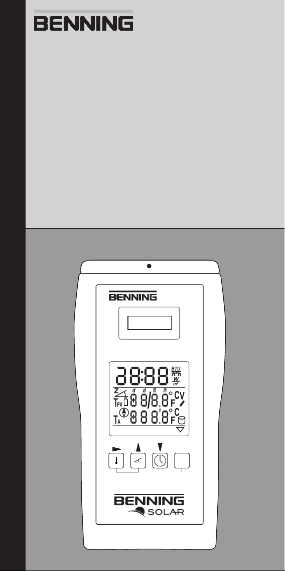
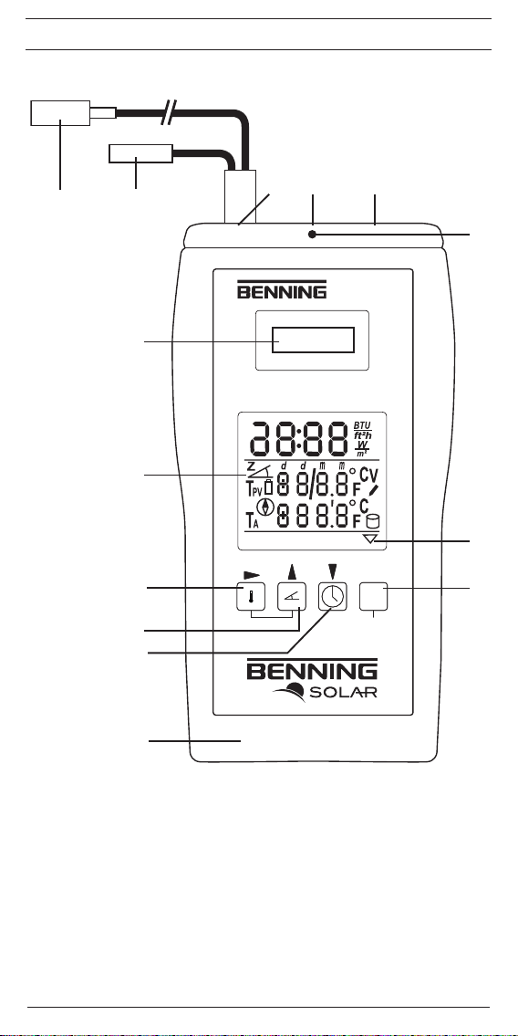
Bild 1: Gerätefrontseite
Fig. 1: Device front
03/ 2012
6
BENNING SUN 2

D
Bedienungsanleitung
BENNING SUN 2
Einstrahlungs- und Temperaturmessgerät für Photovoltaik-Anlagen und thermische Solaranlagen zur Messung der
- solaren Einstrahlung (Bestrahlungsstärke)
- Modul- und Umgebungstemperatur
- Neigungswinkel
- Kompasspeilung
Inhaltsverzeichnis
1. Benutzerhinweise
2. Sicherheitshinweise
3. Lieferumfang
4. Gerätebeschreibung
5. Allgemeine Angaben
6. Umgebungsbedingungen
7. Messbereiche
8. Messen mit dem BENNING SUN 2
9. Instandhaltung
10. Umweltschutz
1. Benutzerhinweise
Diese Bedienungsanleitung richtet sich an
- ausgebildetes Fachpersonal und
- unterwiesene Personen.
Das BENNING SUN 2 ist ausschließlich zur Messung in trockener Umgebung vorgesehen (Näheres hierzu im Abschnitt 6. “Umgebungsbedingungen”).
In der Bedienungsanleitung und auf dem BENNING SUN 2 werden folgende Symbole verwendet:
Warnung vor elektrischer Gefahr!
Steht vor Hinweisen, die beachtet werden müssen, um Gefahren für Menschen zu
vermeiden.
Achtung Dokumentation beachten!
Das Symbol gibt an, dass die Hinweise in der Bedienungsanleitung zu beachten
sind, um Gefahren zu vermeiden.
Dieses Symbol auf dem BENNING SUN 2 bedeutet, dass das BENNING SUN 2
konform zu den EU-Richtlinien ist.
Dieses Symbol erscheint in der Anzeige für entladene Batterien. Sobald das
Batteriesymbol erscheint, tauschen Sie umgehend die Batterien gegen neue
Batterien aus.
03/ 2012
BENNING SUN 2
1

D
2. Sicherheitshinweise
Das Gerät ist gemäß
DIN VDE 0411 Teil 1/ EN 61010-1
gebaut und geprüft und hat das Werk in einem einwand freien Zustand verlassen.
Um diesen Zustand zu erhalten, muss der Anwender die Hinweise und Warnvermerke beachten,
die in dieser Anleitung enthalten sind.
Verwenden Sie ausschließlich, die im Lieferumfang des BENNING SUN 2
enthaltenen Temperatursensoren und Anschlusskabel.
Die Temperatursensoren dürfen nicht an blanke, spannungsführende Teile
kontaktiert werden.
Das BENNING SUN 2 ist ausschließlich zur Messung in trockener Umgebung
vorgesehen.
Ist anzunehmen, dass ein korrekter Betrieb nicht mehr möglich ist, ist das Gerät außer Betrieb
zu setzen.
Es ist anzunehmen, dass ein korrekter Betrieb nicht mehr möglich ist,
- wenn das Gerät oder die Anschlusskabel Beschädigungen aufweisen,
- wenn das Gerät nicht mehr arbeitet,
- nach längerer Lagerung unter ungünstigen Verhältnissen,
- nach schweren Transportbeanspruchungen,
- wenn das Gerät oder die Anschlusskabel feucht sind.
3. Lieferumfang
Zum Lieferumfang des BENNING SUN 2 gehören:
3.1 ein Stück BENNING SUN 2
3.2 ein Stück Modul-/ Umgebungstemperatursensor
3.3 ein Stück Gummischutzrahmen
3.4 ein Stück Kompakt-Schutztasche
3.5 ein Stück USB-Verbindungskabel (A-Stecker auf B-Stecker)
3.6 zwei 1,5 V Mignon/ Typ AA, IEC LR6,
3.7 ein Stück Kurzanleitung,
3.8 ein Stück CD-ROM mit Download-Software, Bedienungsanleitung, Informationsmaterial, etc.
Hinweis auf Verschleißteile:
- Das BENNING SUN 2 wird durch zwei 1,5 V Mignon-Batterien gespeist (IEC LR6). Es dürfen
Alkaline, wiederaufladbare NiCd oder NiMH Batterien verwendet werden.
4. Gerätebeschreibung
siehe Bild 1: Gerätefrontseite
Die in Bild 1 angegebenen Anzeige- und Bedienelemente werden wie folgt bezeichnet:
1
Einstrahlungs-Sensor (PV-Referenzzelle), zur Messung der solaren Einstrahlung
2
Digitalanzeige, für den Messwert, der solaren Einstrahlung, Modul-/ Umgebungstempera-
tur, Neigungswinkel und Kompasspeilung
3
-Taste, zur Messung der Modul- und Umgebungstemperatur
4
-Taste, zur Messung des Neigungswinkels und Kompasspeilung
5
-Taste, zur Anzeige/ Einstellung von Uhrzeit/ Datum
6
Batteriefach auf der Rückseite
7
-Taste, zum kurzzeitigen Speichern der Displayanzeige, bzw. zur Bestätigung von OK/
LOG
8
HOLD-Anzeiger, wenn HOLD-Taste betätigt wurde
9
Markierung für Kompasspeilung
USB-Schnittstelle, zum Anschluss des USB-Verbindungskabels
Buchse (Link), für weitere BENNING-Produkte
Buchse (Probe), zum Anschluss der Temperatursensoren
Umgebungs-Temperatursensor
Modul-Temperatursensor
Gummischutzrahmen
5. Allgemeine Angaben
Das BENNING SUN 2 ist für die Messung der solaren Einstrahlung (Bestrahlungsstärke) sowie
der Modul-/ Umgebungstemperatur von Photovoltaik-Anlagen und thermischen Solaranlagen
vorgesehen. Zusätzlich beinhaltet das BENNING SUN 2 einen digitalen Kompass zur Bestimmung der Himmelsrichtung und einen Neigungswinkelmesser zur Bestimmung der Modul-/
Dachneigung.
Der integrierte Datenlogger mit Echtzeituhr ermöglicht die Speicherung von 5.000 Datensätzen,
bestehend aus Bestrahlungsstärke, Modul- und Umgebungstemperatur sowie eines Zeit-/ Datumstempels. Das Messintervall des Datenloggers ist in Minutenschritten von 1 Min. bis 60 Min.
03/ 2012
BENNING SUN 2
2

D
einstellbar. Die Auslesung des Datenloggers erfolgt über die integrierte USB-Schnittstelle und
mit Hilfe des auf der CD-ROM bendlichen Downloadprogramms.
Alle Messergebnisse werden auf dem großen LCD-Display ausgegeben.
- Speicherkapazität des Datenloggers: 5.000 Datensätze, bestehend aus Bestrahlungsstärke, Modul- und Umgebungstemperatur sowie Datum-/ Zeitstempel
- Integrierte Echtzeituhr
- Schnittstelle: USB
- Geräteabmessungen:
(L x B x H) = 150 x 80 x 33 mm
- Gerätegewicht:
265 g ohne Temperaturfühler/ USB-Kabel
347 g mit Temperaturfühler/ USB-Kabel
6. Umgebungsbedingungen
- Das BENNING SUN 2 ist für Messungen in trockener Umgebung vorgesehen.
- Barometrische Höhe bei Messungen: 0 m bis maximal 2000 m
- Verschmutzungsgrad: 2
- Schutzart: IP 40 (DIN VDE 0470-1, IEC/ EN 60529)
4 - erste Kennziffer: Schutz gegen Zugang zu gefährlichen Teilen und Schutz gegen feste
Fremdkörper, > 1 mm Durchmesser
0 - zweite Kennziffer: Kein Schutz gegen Wasser
- EMC: IEC/ EN 61326,
- Arbeitstemperatur und relative Luftfeuchte:
Bei Arbeitstemperatur von 0 °C bis 50 °C: relative Luftfeuchte kleiner 80 %, nicht kondensierend
- Lagerungstemperatur: Das BENNING SUN 2 kann bei Temperaturen von - 20 °C bis + 60 °C
(Luftfeuchte 0 bis 80 %) gelagert werden. Dabei sind die Batterien aus dem Gerät herauszunehmen.
7. Messbereiche
Bemerkung: Die Messgenauigkeit wird angegeben als Summe aus
- einem relativen Anteil des Messwertes und
- einer Anzahl von Digit (d.h. Zahlenschritte der letzten Stelle).
Diese Messgenauigkeit gilt bei Temperaturen von 0 °C bis 50 °C und einer relativen Luftfeuchtigkeit kleiner 80 %.
7.1 Solare Einstrahlung
Messbereich Auflösung Messgenauigkeit
100 Wm² - 1250 Wm² 1 W/m² ± (5 % + 5 Digit)
30 BTU/h/ft² - 400 BTU/h/ft² 1 BTU/h/ft² ± (5 % + 5 Digit)
7.2 Modul- und Umgebungstemperatur
Messbereich Auflösung Messgenauigkeit
- 30 °C bis + 125 °C 1 °C ± (1 % + 1 Digit)
- 22 °F bis + 257 °F 1 °F ± (1 % + 1 Digit)
7.3 Neigungswinkel
Messbereich Auflösung Messgenauigkeit
0° - 80° 1° ± 2°
7.4 Kompasspeilung (Ausrichtung)
Messbereich Auflösung Messgenauigkeit
0° - 360° 1° ± 10°
8. Messen mit dem BENNING SUN 2
8.1 Vorbereiten der Messung
Benutzen und lagern Sie das BENNING SUN 2 nur bei den angegebenen Lager- und Arbeitstemperaturbedingungen.
- Starke Störquellen in der Nähe des BENNING SUN 2 können zu instabiler Anzeige und zu
Messfehlern führen.
Vor jeder Inbetriebnahme überprüfen Sie das Gerät und die Anschlusskabel
auf Beschädigungen.
03/ 2012
BENNING SUN 2
3
D
8.1.1 Ein-, Ausschalten des BENNING SUN 2
- Durch gleichzeitiges Betätigen der Tasten 3 und 4 für ca. 2 Sekunden wird das
BENNING SUN 2 eingeschaltet. Ein Signalton bestätigt dies. Erneutes Drücken der Tasten
für > 2 Sekunden schaltet das Gerät aus.
- Das BENNING SUN 2 schaltet sich nach ca. 2 Minuten selbstständig ab (APO, Auto-Power-
Off). Es schaltet sich wieder ein, wenn die Tasten 3 und 4 betätigt werden.
8.1.2 Prüfung des Batteriezustandes
- Das BENNING SUN 2 führt während des Einschaltens und im laufenden Betrieb einen automatischen Batterietest durch.
- Entladene Batterien werden durch ein Batteriesymbol im LCD-Dis play dargestellt. Sobald
das Batteriesymbol erscheint sind die Batterien umgehend zu ersetzen (siehe Abschnitt
9.2)
- Zur Prüfung des Batteriezustandes drücken Sie die Taste 7 für > 5 Sek., um den Datenlogger aufzurufen. In der Digitalanzeige wird „LOG“ eingeblendet.
- Das Display zeigt wechselnd den belegten/ freien Speicher und die Batteriespannung/ das
Messintervall in Minuten an.
- Sobald die Batteriespannung unter 1,8 V sinkt, tauschen Sie bitte umgehend die Batterien
gegen neue Batterien aus, um Fehlmessungen zu vermeiden (siehe Abschnitt 9.2).
- Drücken Sie die Taste 3 oder 4, um den Datenlogger zu verlassen.
8.1.3 Messung der solaren Einstrahlung (Bestrahlungsstärke)
- Nach dem Einschalten des BENNING SUN 2 wird die solare Einstrahlung fortlaufend in der
Digitalanzeige 2 angezeigt.
- Bestrahlungsstärken unter 100 W/m² werden nicht angezeigt. Anzeige: „- - -".
- Legen Sie das BENNING SUN 2 auf die Moduloberfläche und betätigen Sie im Bedarfsfall
die -Taste 7 zur kurzzeitigen Speicherung des Messwertes in der Digitalanzeige.
- Zur Speicherung der solaren Einstrahlung über einen längeren Zeitraum nutzen Sie bitte
den Datenlogger, wie unter Abschnitt 8.2 beschrieben.
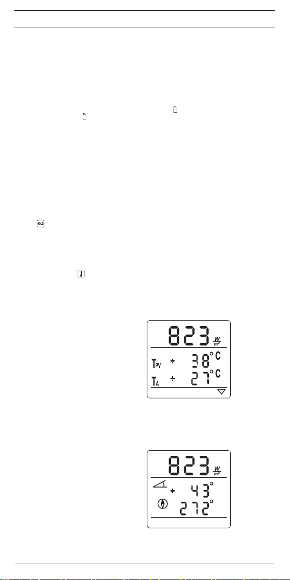
8.1.4 Messung der Modul- und Umgebungstemperatur
- Schließen Sie den Modul-/ Umgebungstemperatursensor über die Buchse an das
BENNING SUN 2 an.
- Betätigen Sie die -Taste 3 zur Anzeige der Modul- (TPV) und Umgebungstemperatur
(TA).
- Kontaktieren Sie den Modul-Temperatursensor auf das PV-Modul und warten Sie bis der
Temperatursensor die Temperatur des PV-Moduls angenommen hat.
- Zur Speicherung der Modul- und Umgebungstemperatur über einen längeren Zeitraum nutzen Sie den Datenlogger, wie unter Abschnitt 8.2 beschrieben.
Solare Einstrahlung ►
PV-Modultemperatur
Umgebungstemperatur
8.1.5 Messung des Neigungswinkels
- Betätigen Sie die Taste 4 zur Anzeige des Neigungswinkels und der Kompasspeilung.
- Der Neigungswinkel zur Horizontalen wird fortlaufend in der Digitalanzeige 2 angezeigt.
- Legen Sie das BENNING SUN 2 auf die Moduloberfläche und betätigen Sie im Bedarfsfall
die HOLD-Taste 7 zur kurzzeitigen Speicherung des Messwertes in der Digitalanzeige.
Solare Einstrahlung ►
Neigungswinkel
Kompasspeilung
8.1.6 Nullabgleich des Neigungswinkels
- Legen Sie das Gerät auf eine ebene Fläche und drücken Sie die Taste 4 für > 5 Sek. bis
das Symbol „Z“ in der Digitalanzeige 2 blinkt.
03/ 2012
►
►
►
►
BENNING SUN 2
4

D
- Drücken Sie die Taste 4 erneut, um den Wert „+SET“ zu speichern.
- Drehen Sie das Gerät um 180° und drücken Sie die Taste 4 erneut, um den Wert „-SET“ zu
speichern. Der Neigungswinkel wurde auf Null abgeglichen, in der Digitalanzeige wird das
Symbol „Z“ eingeblendet.
- Drücken Sie die Taste 4 erneut für > 5 Sek., um die Einstellung zu verlassen. Das Symbol
„Z“ wird ausgeblendet.
8.1.7 Kompasspeilung (Ausrichtung)
- Betätigen Sie die Taste 4 zur Anzeige des Neigungswinkels und der Kompasspeilung.
- Die Kompasspeilung wird fortlaufend in der Digitalanzeige 2 angezeigt.
- Zur Bestimmung der Himmelsrichtung halten Sie das Gerät waagerecht. Sobald der Nei-
gungswinkel +/- 20° überschreitet, wird die Kompasspeilung mit „- - -‟ angezeigt und eine
Messung ist nicht möglich.
- Halten Sie die Markierung der Kompasspeilung 9 in die Richtung, die Sie bestimmen möchten. Die Richtung wird in Grad angezeigt:
0° = Norden, 90° = Westen, 180° = Süden, 270° = Osten
- Beachten Sie, dass metallische Objekte oder stromdurchflossene Leiter die Messgenauigkeit des Gerätes beeinflussen können.
Solare Einstrahlung ►
Neigungswinkel
Kompasspeilung
8.2 Datenlogger (Messwertspeicher) mit Echtzeituhr
Das BENNING SUN 2 kann bis zu 5.000 Datensätze, bestehend aus der solaren Einstrahlung
(Bestrahlungsstärke), der Modul- und der Umgebungstemperatur, speichern. Jeder Datensatz
wird mit einem Zeit-/ Datumstempel versehen. Die Auslesung der Messdaten erfolgt über die
integrierte USB-Schnittstelle und mit Hilfe eines Downloadprogramms. Das Messintervall (Zeitraum zwischen zwei Messungen) des BENNING SUN 2 ist in Minutenschritten von 1 Min. bis
60 Min. einstellbar.
8.2.1 Datenlogger-Setup
Das Setup ermöglicht die Einstellung des Messintervalls, des Speicher-Modus und das Löschen
aller Datensätze.
- Drücken Sie die Taste 7 für > 5 Sek., um den Datenlogger aufzurufen. In der Digitalanzeige
2
wird „LOG“ eingeblendet.
- Das Display zeigt wechselnd den belegten/ freien Speicher und die Batteriespannung/ das
Messintervall in Minuten an.
- Zur Einstellung des Messintervalls (1 Min. bis 60 Min.) drücken Sie erneut die Taste 7 für
> 5 Sek. Anzeige: „Int“. Über die Tasten 4 und 5 kann der Wert in Minutenschritten erhöht
bzw. reduziert werden.
- Drücken Sie die Taste 3, um den Speicher-Modus anzuzeigen. Anzeige: „dAtA“. Über die
Tasten 4 und 5 können Sie „StOP“ (bei vollem Speicher) oder „rOLL“ (die ältesten Messwerte werden fortlaufend überschrieben) auswählen.
- Drücken Sie erneut die Taste 3, um den Speicher zu löschen. Anzeige: „dEL“. Über die
Tasten 4 und 5 können Sie „yES“ oder „nO“ auswählen, um den kompletten Speicher zu
löschen.
- Über die Taste 7 (OK) kann die Einstellung jederzeit gespeichert und der Datenlogger verlassen werden.
- Drücken Sie die Taste 3 oder 4, um den Datenlogger zu verlassen.
belegter Speicher Batteriespannung
freier Speicher Messintervall
►
►
▲ wechselnde Anzeige ▲
└──────────────┘
(1 Min. - 60 Min.)
03/ 2012
BENNING SUN 2
5

D
8.2.2 Datenlogger starten/ stoppen
- Drücken Sie die Taste 7 (LOG) für > 5 Sek., um den Datenlogger zu aktivieren. Anzeige:
„LOG“.
- Drücken Sie erneut die Taste 7 (LOG) und anschließend die Taste 7 (OK), um „run“ zu
bestätigen. Die Messwerte werden mit einem Zeit-/ Datumstempel in den internen Speicher
geschrieben. Die Digitalanzeige 2 erlischt und das Gerät schaltet in den stromsparenden
Bereitschaftsmodus.
- Um den Fortschritt des Datenloggers anzuzeigen, drücken Sie eine beliebige Taste. Die
Digitalanzeige erwacht kurzzeitig und erlischt an schließend erneut.
- Zum Stoppen des Datenloggers drücken Sie eine beliebige Taste, um den Datenlogger anzuzeigen. Drücken Sie die Taste 7 (LOG) und anschließend die Taste 7 (OK), um „StOP“
zu bestätigen.
- Drücken Sie die Taste 3 oder 4, um den Datenlogger zu verlassen.
8.2.3 Datenlogger über USB-Schnittstelle auslesen
- Installieren Sie einmalig den Treiber und das Downloadprogramm von der CD-ROM.
- Schließen Sie das BENNING SUN 2 über das USB-Verbindungskabel an den PC an und
schalten Sie das Gerät ein.
- Starten Sie das Downloadprogramm und klicken Sie unter Optionen auf „COM-Ports aktualisieren“.
- Wählen Sie den verwendeten COM-Port aus und klicken Sie auf „Download“.
- Der Messwertdownload startet.
Fehlerbehebung:
- Einer der häufigsten Verbindungsfehler ist die Auswahl eines falschen COM-Ports.
- Sollte der Messwertdownload nicht erfolgen, überprüfen Sie den verwendeten COM-Port
über den Geräte-Manager Ihres Systems.
- Sobald das BENNING SUN 2 über das USB-Verbindungskabel mit dem PC verbunden wurde, ist der Hardware-Treiber und somit der verwendete COM-Port im Geräte-Manager unter
Anschlüsse (COM und LPT) ersichtlich, z. B. Silicon Labs CP210x USB to UART Bridge
(COM14)
8.2.4 Einstellung von Datum und Uhrzeit
- Drücken Sie die Taste 5, um die Uhrzeit/ das Datum in der Digitalanzeige 2 anzuzeigen.
- Drücken Sie erneut die Taste 5 für > 5 Sek. bis die Stundenanzeige blinkt.
- Die Taste-► 3 wählt das Uhrzeit/ Datums-Feld aus (Feld blinkend).
- Über die Taste-▲ 4 und ▼ 5 wird der Wert erhöht bzw. verringert.
- Drücken Sie die Taste 7 (OK), um die Einstellung zu speichern.
Uhrzeit/ 24 Stundenanzeige ►
Tag/ Monat
8.2.5 Anzeigeeinheit ändern
- Drücken Sie die Taste-
- Betätigen Sie die Taste-► 3, um die Einheit der solaren Einstrahlung oder der Temperatur
anzuwählen.
- Betätigen Sie die Tasten-▲ 4 oder ▼ 5, um zwischen den Einheiten °C oder °F bzw.
zwischen W/m² oder BTU/hr/ft² zu wechseln.
- Drücken Sie die Taste 7 (OK), um die Einstellung zu speichern.
9. Instandhaltung
Das Gerät nicht öffnen. Es enthält keine durch den Benutzer wartbaren Komponenten. Repara-
tur und Service kann nur durch qualiziertes Personal erfolgen.
9.1 Reinigung
Reinigen Sie das Gehäuse äußerlich mit einem sauberen und trockenen Tuch (Ausnahme spezielle Reinigungstücher). Verwenden Sie keine Lösungs- oder Scheuermittel, um das Gerät zu reinigen. Achten Sie unbedingt darauf, dass das Batteriefach und die Batteriekontakte nicht durch
auslaufendes Batterie-Elektrolyt verunreinigt werden.
Falls Elektrolytverunreinigungen oder weiße Ablagerungen im Bereich der Batterie oder des Batteriegehäuses vorhanden sind, reinigen Sie auch diese mit einem trockenen Tuch.
03/ 2012
3
►
Jahr
►
für >5 Sek. bis die Anzeigeeinheit der Temperatur blinkt.
BENNING SUN 2
6

D
9.2 Batteriewechsel
Das BENNING SUN 2 wird durch zwei 1,5 V Mignon-Batterien/ Typ AA (IEC LR6) gespeist.
Ein Batteriewechsel ist erforderlich sobald die Batteriespannung unter 1,8 V sinkt (siehe Abschnitt 8.1.2).
So wechseln Sie die Batterien:
- Schalten Sie das BENNING SUN 2 aus.
- Legen Sie das BENNING SUN 2 auf die Frontseite und schieben den Batteriedeckel vom
Unterteil ab.
- Heben Sie die entladenen Batterien aus dem Batteriefach.
- Legen Sie dann die Batterien in die dafür vorgesehenen Stellen im Batteriefach (achten Sie
bitte unbedingt auf die korrekte Polung der Batterien).
- Schieben Sie den Batteriedeckel an das Unterteil.
9.3 Kalibrierung
Um die angegebenen Genauigkeiten der Messergebnisse zu erhalten, muss das Gerät regelmäßig durch unseren Werksservice kalibriert werden. Wir empfehlen ein Kalibrierintervall von
einem Jahr. Senden Sie hierzu das Gerät an folgende Adresse:
Benning Elektrotechnik & Elektronik GmbH & Co. KG
Service Center
Robert-Bosch-Str. 20
D – 46397 Bocholt
9.4 Ersatzteile
Modul-/ Umgebungstemperatursensor TN: 1005 6280
Kompakt-Schutztasche TN: 1005 6270
USB-Verbindungskabel (A-Stecker auf B-Stecker) TN: 1000 8853
10. Umweltschutz
Bitte führen Sie das Gerät am Ende seiner Lebensdauer den zur Verfügung ste henden Rückgabe- und Sammelsystemen zu.
03/ 2012
BENNING SUN 2
7

Operating Manual
BENNING SUN 2
Insolation and temperature measuring instrument for photovoltaic systems and solar thermal
systems for measuring the following :
- insolation
- module temperature and ambient temperature
- angle of inclination
- compass bearing
Table of Contents
1. User instructions
2. Safety instructions
3. Scope of delivery
4. Device description
5. General information
6. Ambient conditions
7. Measuring ranges
8. Measuring with the BENNING SUN 2
9. Maintenance
10. Environmental protection
1. User instructions
This operating manual is intended for
- qualied technical personnel and
- trained personnel.
The BENNING SUN 2 is intended for measurements under dry ambient conditions only (for
details, refer to section 6 "Ambient conditions").
The following symbols are used in this operating manual and on the BENNING SUN 2:
Warning of electrical danger!
Indicates instructions which must be followed to avoid danger to persons.
Attention! Please observe documentation!
The symbol indicates that the instructions in the operating manual must be observed.
This symbol on the BENNING SUN 2 means that the BENNING SUN 2 complies
with the EU directives.
This symbol appears on the display to indicate discharged batteries. As soon as the
battery symbol appears, immediately replace the batteries by new ones.
03/ 2012
BENNING SUN 2
8

2. Safety instructions
The instrument is built and tested in accordance with
DIN VDE 0411 Part 1/ EN 61010-1
and has left the factory in perfectly safe technical condition.
To preserve this condition and to ensure safe operation of the device, the user must observe the
notes and warnings given in this operating manual at all times.
Only use the temperature sensors and connecting cables included in the
scope of delivery of the BENNING SUN 2.
Do not apply any electrical contact between the temperature sensors and bare
live parts.
The BENNING SUN 2 is intended for measurements under dry ambient
conditions only.
If it is assumed that correct operation is no longer possible, the device must be switched off
immediately.
Safe operation can be assumed to be no longer possible, if
- the device or the connecting cables show visible damages,
- the device no longer works,
- the device has been stored under unfavourable conditions for a longer period of time,
- the device has been exposed to extraordinary stress during transport,
- the device or the measuring lines have been exposed to moisture.
3. Scope of delivery
The scope of delivery of the BENNING SUN 2 includes:
3.1 one BENNING SUN 2
3.2 one module / ambient temperature sensor
3.3 one protective rubber holster
3.4 one compact protective pouch
3.5 one USB connecting cable (A plug to B plug)
3.6 two 1.5 V batteries of type AA, IEC LR6,
3.7 one quick reference guide,
3.8 one CD-ROM with download software, operating manual, information material etc.
Parts subject to wear:
- The BENNING SUN 2 is supplied by means of two 1.5 V batteries of type AA (IEC LR6). It is
allowed to use alkaline rechargeable NiCd or NiMH batteries.
4. Device description
See gure 1: Device front
The display and operating elements shown in gure 1 are designated as follows:
1
Insolation sensor (PV reference cell), for measuring the insolation
2
Digital display, for displaying the measured values of insolation, module / ambient tempera-
ture, angle of inclination and compass bearing
3
key, for measuring the module temperature and ambient temperature
4
key, for measuring the angle of inclination and the compass bearing
5
key, for displaying / setting the time / date
6
Battery compartment on the back
7
key, for temporary storage of the display indication or to confirm OK / LOG
8
HOLD indicator, active when the HOLD key has been actuated
9
Marking for compass bearing
USB interface, for connecting the USB connecting cable
Jack (LINK), for other BENNING products
Jack (PROBE), for connecting temperature sensors
Ambient temperature sensor
Module temperature sensor
Protective rubber holster
5. General information
The BENNING SUN 2 is intended for measuring the insolation (solar irradiance) as well as the
module / ambient temperature of photovoltaic systems and solar thermal systems. Additionally,
the BENNING SUN 2 comprises a digital compass for determining the cardinal direction as well
as an inclinometer for determining the module / roof pitch.
The integrated data logger with real-time clock allows the storage of 5000 data records including the values for insolation, module temperature and ambient temperature as well as a time /
date stamp. The measuring interval of the data logger can be set from 1 minute to 60 minutes in
increments of one minute. The data of the data logger can be read out via the integrated USB
interface and by means of the download software on the enclosed CD-ROM.
03/ 2012
BENNING SUN 2
9

All measuring results are displayed on the large LC display.
- Storage capacity of the data logger: 5000 data records, including the values for insolation,
module temperature and ambient temperature as well as a time / date stamp
- integrated real-time clock
- Interface: USB
- Dimensions of the device:
(L x W x H) = 150 x 80 x 33 mm
- Weight of the device:
265 g without temperature sensors / USB cable
347 g including temperature sensors / USB cable
6. Ambient conditions
- The BENNING SUN 2 is intended for measurements under dry ambient conditions,
- Maximum barometric height for measurements: 0 m to max. 2000 m
- Contamination level: 2
- Protection category: IP 40 (DIN VDE 0470-1, IEC/ EN 60529)
4 – first index: protection against access to dangerous parts and protection against solid
impurities of a diameter > 1.0 mm
0 – second index: No protection against water
- EMC: IEC/ EN 61326,
- Operating temperature and relative air humidity:
For operating temperatures from 0 °C to 50 °C: relative air humidity lower than 80 %, non-
condensing
- Storage temperature: The BENNING SUN 2 can be stored at temperatures between - 20 °C
and + 60 °C (air humidity 0 to 80 %). During storage, the batteries must be removed.
7. Measuring ranges
Note: The measuring accuracy is specied as the sum of:
- a relative part of the measured value and
- a number of digits (i.e. counting steps of the last digit).
This measuring accuracy applies to temperatures from 0 °C to 50 °C and a relative air humidity
lower than 80 %.
7.1 Insolation
Measuring range Resolution Measuring accuracy
100 Wm² to 1250 Wm² 1 W/m² ± (5 % + 5 digits)
30 BTU/h/ft² to 400 BTU/h/ft² 1 BTU/h/ft² ± (5 % + 5 digits)
7.2 Module temperature and ambient temperature
Measuring range Resolution Measuring accuracy
- 30 °C to + 125 °C 1 °C ± (1 % + 1 digit)
- 22 °F to + 257 °F 1 °F ± (1 % + 1 digit)
7.3 Angle of inclination
Measuring range Resolution Measuring accuracy
0° to 80° 1° ± 2°
7.4 Compass bearing (orientation)
Measuring range Resolution Measuring accuracy
0° to 360° 1° ± 10°
8. Measuring with the BENNING SUN 2
8.1 Preparing the measurement
Operate and store the BENNING SUN 2 at the specied storage and operating temperatures
only!
- Strong sources of interference in the vicinity of the BENNING SUN 2 might involve unstable
readings and measuring errors.
Before commissioning, always check the device as well as all connecting
cables for damages.
03/ 2012
BENNING SUN 2
10

8.1.1 Switching the BENNING SUN 2 ON/OFF
- Press the keys 3 and 4 at the same time for approx. 2 seconds to switch the BENNING
SUN 2 on. This will be confirmed by an acoustic signal. Press the keys again for > 2 seconds
to switch the device off.
- The BENNING SUN 2 is switched off automatically after approx. 2 minutes (APO, Auto-
Power-Off). It switches on again when the keys 3 and 4 are actuated.
8.1.2 Testing the battery condition
- During switch-on and operation, the BENNING SUN 2 carries out an automatic battery test.
- Discharged batteries are indicated by a battery symbol on the LC display. As soon as the
battery symbol appears, the batteries have to be replaced by new ones immediately (see
section 9.2).
- For testing the battery condition, press the key 7 for > 5 seconds to call the data logger.
"LOG" appears on the digital display.
- Alternately, the display shows the occupied / free memory space as well as the battery voltage / the measuring interval in minutes.
- As soon as the battery voltage falls below 1.8 V, immediately replace the batteries by new
ones in order to prevent incorrect measurements (see section 9.2).
- Press the key 3 or 4 to exit the data logger.
8.1.3 Measuring the insolation (solar irradiance)
- After having switched the BENNING SUN 2 on, the insolation is displayed continuously on
the digital display 2.
- Solar irradiance below 100 W/m² are not indicated. Display: "- - - ".
- Place the BENNING SUN 2 onto the surface of the photovoltaic module and press the
key 7, if necessary, to store the measured value temporarily in the digital display.
- To store the insolation value for a longer period of time, please use the data logger as described in section 8.2.
8.1.4 Measuring the module temperature and the ambient temperature
- Connect the module / ambient temperature sensor to the BENNING SUN 2 by means
of the jack .
- Press the key 3 to display the module temperature (TPV) and the ambient temperature
(TA).
- Bring the module temperature sensor into contact with the PV module and wait until the
temperature sensor has measured the temperature of the PV module.
- To store the module temperature and ambient temperature values for a longer period of time,
please use the data logger as described in section 8.2.
insolation ►
PV module temperature
ambient temperature
8.1.5 Measuring the angle of inclination
- Press the key 4 to display the angle of inclination and the compass bearing.
- The angle of inclination with respect to the horizontal is indicated continuously on the digital
display 2.
- Place the BENNING SUN 2 onto the surface of the photovoltaic module and press the HOLD
key 7, if necessary, to store the measured value temporarily in the digital display.
insolation ►
angle of inclination
compass bearing
03/ 2012
►
►
►
►
BENNING SUN 2
11

8.1.6 Null balance of the angle of inclination
- Place the device onto a plane surface and press the key 4 for > 5 seconds until the "Z"
symbol starts flashing on the digital display 2.
- Press the key 4 again to store the "+SET" value.
- Turn the device by 180° and press the key 4 again to store the "-SET" value. The angle of
inclination has been balanced to null and the "Z" symbol is shown on the digital display.
- Press the key 4 again for > 5 seconds to exit the setting. The "Z" symbol disappears from
the LC display.
8.1.7 Compass bearing (orientation)
- Press the key 4 to display the angle of inclination and the compass bearing.
- The compass bearing is indicated continuously on the digital display 2.
- To determine the cardinal direction, hold the device horizontally. As soon as the angle of
inclination exceeds +/- 20°, the compass bearing indication shows "- - -" and it is not possible
to take a bearing.
- Hold the marking 9 for the compass bearing in the direction which you would like to
determine. The direction is displayed in degrees:
0° = North, 90° = West, 180° = South, 270° = East
- Please observe that metallic objects or live conductors might affect the measuring accuracy
of the device.
insolation ►
angle of inclination
compass bearing
8.2 Data logger (measured value memory) with real-time clock
The BENNING SUN 2 can store up to 5000 data records consisting of the values for insolation (solar irradiance), module temperature and ambient temperature. Each data record will be
provided with a time / date stamp. The measuring data can be read out via the integrated USB
interface and by means of a download software. The measuring interval (time between two
measurements) of the BENNING SUN 2 can be set from 1 minute to 60 minutes in increments
of one minute.
8.2.1 Data logger set-up
The set-up allows the user to set the measuring interval, the memory mode and to delete all
data records.
- Press the key 7 for > 5 seconds to call the data logger. "LOG" appears on the digital display
2
.
- Alternately, the display shows the occupied / free memory space as well as the battery
voltage / the measuring interval in minutes.
- To set the measuring interval (1 minute to 60 minutes), press the key 7 again for > 5
seconds. Display: "Int". Press the key 4 or key 5 to increase or decrease the value in
increments of one minute.
- Press the key 3 to display the memory mode. Display: "dAtA". Press the key 4 or key 5
to select "StOP" (if the memory is full) or "rOLL" (if you want to overwrite the oldest measured
values continuously).
- Press the key 3 again to delete the memory. Display: "dEL". Select "yES" or "nO" by
pressing the 4 or 5 keys to delete the entire memory.
- By means of the key 7 (OK), it is possible to store the setting at any time and to exit the data
logger.
- Press the key 3 or 4 to exit the data logger.
occupied memory
space
free memory space measuring interval
►
►
▲ alternating display ▲
└──────────────┘
battery voltage
(1 min. to 60 min.)
03/ 2012
BENNING SUN 2
12

8.2.2 Starting / stopping the data logger
- Press the key 7 (LOG) for > 5 seconds to activate the data logger. Display: "LOG".
- Press the key 7 (LOG) again and then the key 7 (OK) to confirm "run". The measured
values are written into the internal memory including a time / date stamp. The digital display
2
goes out and the device switches over into the energy-saving stand-by mode.
- Press any key to display the progress of the data logger. The digital display briefly goes on
and then goes out again.
- If you want to stop the data logger, press any key to display the data logger. Press the key
7
(LOG) and then the key 7 (OK) to confirm "StOP".
- Press the key 3 or 4 to exit the data logger.
8.2.3 Reading out the data logger via the USB interface
- Install the driver and the download software from the CD-ROM once.
- Connect the BENNING SUN 2 to your PC by means of the USB connecting cable and switch
the device ON.
- Start the download program, go to "Tools" and click "Refresh Ports".
- Select the COM port used and click "Download".
- The download of measured values starts.
Troubleshooting:
- One of the most frequent connection errors is the selection of the wrong COM port.
- If the measured values are not downloaded, verify the COM port used by means of the
Device Manager of your system.
- As soon as the BENNING SUN 2 has been connected to your PC by means of the USB
connecting cable, the hardware driver and thus the COM port used can be viewed in the
Device Manager under "Ports (COM & LPT)", e.g. Silicon Labs CP210x USB to UART
Bridge (COM14).
8.2.4 Setting the date and the time
- Press the key 5 to display the time / date on the digital display 2.
- Press the key 5 again for > 5 seconds until the hour display starts ashing.
- Press the ► key 3 to select the time / date eld (eld is ashing).
- Press the ▲ key 4 or ▼ key 5 to increase or decrease the value.
- Press the key 7 (OK) to store the setting.
time / 24-hour display ►
day / month
8.2.5 Changing the displayed unit
- Press the 3 key for > 5 seconds until the displayed temperature unit starts flashing.
- Press the ► 3 key to select the respective unit for insolation or temperature.
- Press the ▲ 4 or ▼ 5 key to change between the units °C or °F or between the units W/m²
or BTU/hr/ft².
- Press the 7 key (OK) to store the setting.
9. Maintenance
Do not open the device. It does not contain any components requiring maintenance by the user.
Repair and service must be carried out by qualied personnel only!
9.1 Cleaning
Clean the exterior of the device with a clean dry cloth (exception: special cleaning wipers). Do not
use any solvents or abrasives to clean the device. Make sure that the battery compartment and
the battery contacts are not contaminated by leaking battery electrolyte.
If there are electrolyte contamination or white deposits in the area of the battery or the battery
housing, clean these areas as well by means of a dry cloth.
9.2 Battery replacement
The BENNING SUN 2 is supplied by means of two 1.5 V batteries of type AA (IEC LR6).
It is necessary to replace the batteries as soon as the battery voltage falls below 1.8 V (see
section 8.1.2).
Proceed as follows to replace the battery:
- Switch the BENNING SUN 2 off.
- Put the BENNING SUN 2 face down and slide the battery compartment cover off the bottom
03/ 2012
►
year
►
BENNING SUN 2
13

part of the device.
- Remove the discharged batteries from the battery compartment.
- Then, insert the batteries into the battery compartment at the provided places (please
observe correct polarity of the batteries).
- Slide the battery compartment cover back onto the bottom part of the device.
9.3 Calibration
To maintain accuracy of the measuring results, the device must be recalibrated in regular intervals by our factory service. We recommend recalibrating the device once a year. For this
purpose, send the device to the following address:
Benning Elektrotechnik & Elektronik GmbH & Co. KG
Service Center
Robert-Bosch-Str. 20
D – 46397 Bocholt
9.4 Spare parts
Module / ambient temperature sensor part no.: 1005 6280
Compact protective pouch part no.: 1005 6270
USB connecting cable (A plug to B plug) part no.: 1000 8853
10. Environmental protection
At the end of product life, dispose of the unserviceable device via appropriate return
or collecting facilities provided in your community.
03/ 2012
BENNING SUN 2
14

Benning Elektrotechnik & Elektronik GmbH & Co. KG
Phone: +49 (0) 2871 - 93 - 0 • Fax: +49 (0) 2871 - 93 - 429
www.benning.de • E-Mail: duspol@benning.de
Münsterstraße 135 - 137
D - 46397 Bocholt
 Loading...