


Installation Tester
BENNING IT 130
Short instructions
GB: Detailed instruction manual on enclosed CD-Rom.

BENNING IT 130 short instructions
Benning Elektrotechnik & Elektronik GmbH & Co. KG
Münsterstraße 135 - 137
D - 46397 Bocholt
Phone: +49 (0) 2871 - 93 - 0 • Fax: +49 (0) 2871 - 93 - 429
www.benning.de • duspol@benning.de
© 2014 BENNING
This document must not be reproduced or used in any other form without the express written consent
of BENNING.
IDNR. 20 752 285 TN: 10110214.00

BENNING IT 130 short instructions
Table of Contents
1 Start up guide ................................................................................................................................... 4
1.1 Safety and operational considerations .................................................................................... 4
1.2 Front and connector panel ....................................................................................................... 5
1.3 Standard scope of delivery ...................................................................................................... 7
1.4 Indications and meaning of symbols ....................................................................................... 7
1.5 Selecting measuring functions ................................................................................................. 8
1.6 Switch position „AUTO“ ........................................................................................................... 9
1.7 Settings („SETTINGS“) ............................................................................................................ 9
1.8 Measured value memory ....................................................................................................... 10
1.9 Batteries and fuses ................................................................................................................ 10
1.10 Calibration and service .......................................................................................................... 12
1.11 Optional accessories ............................................................................................................. 11
2 Measurements ................................................................................................................................ 12
2.1 Null balance (compensation) of the test cables ..................................................................... 13
2.2 TRMS voltage (V AC/DC), frequency and phase sequence (rotary field) ............................. 14
2.3 Insulation resistance .............................................................................................................. 15
2.4 Low-impedance resistance/ continuity test ............................................................................ 16
2.5 Residual current operated device (RCD) .............................................................................. 17
2.6 Loop impedance .................................................................................................................... 18
2.7 Line impedance ..................................................................................................................... 19
2.8 Earth resistance ..................................................................................................................... 20
2.9 Current ................................................................................................................................... 21
2.10 Luminous intensitiy ................................................................................................................ 22
2.11 First fault current in IT supply system (ISFL) ......................................................................... 22
- 2 -
BENNING IT 130 short instructions
1 Start-up guide
1.1 Safety and operational considerations
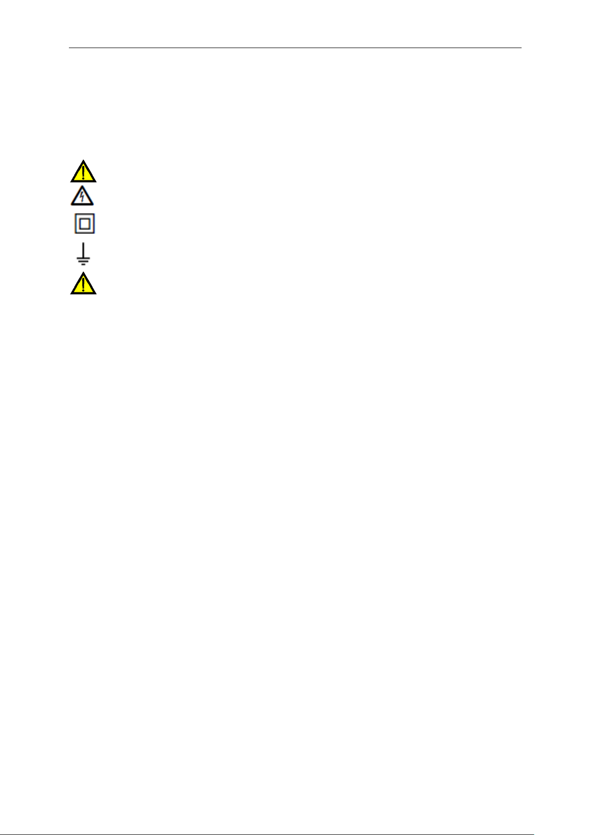
The following symbols are used in the user manual and on the test equipment:
Important, danger, must comply with documentation!
Warning of electrical danger!
Protection class II
Ground (voltage to earth)
Warnings related to safety – general information
This document is not a supplement to the Instruction manual! Please find the operating
manual as PDF file on the enclosed CD-ROM.
If the test equipment is used in a manner not specified in this user manual, the
protection provided by the equipment could be impaired!
Read this user manual carefully, otherwise the use of the instrument may be dangerous
for the operator, the instrument or for the equipment under test!
Do not use the instrument or any of the accessories if any damage is noticed!
Consider all generally known precautions in order to avoid risk of electric shock while
dealing with hazardous voltages!
In case a fuse has blown follow the instructions in this manual in order to replace it!
Use only fuses that are specified!
Do not use the instrument in AC supply systems with voltages higher than 550 V AC.
Service, repairs or adjustment of instruments and accessories is only allowed to be
carried out by a competent authorized personnel!
Please use standard or optional BENNING accessories only which are available from
your authorized specialty retailer!
Consider that protection category of some accessories is lower than of the instrument.
Test tips and Tip "Commander" have removable caps. If they are removed the
protection falls to CAT II. Check markings on accessories!
cap off, 18 mm tip: CAT II up to 1000 V to earth
cap on, 4 mm tip: CAT II 1000 V / CAT III 600 V / CAT IV 300 V to earth
The instrument come supplied with rechargeable Ni-MH battery cells. The cells should
only be replaced with the same type as defined on the battery compartment label or as
described in this manual. Do not use standard alkaline battery cells while the power
supply adapter is connected, otherwise they may explode!
Hazardous voltages exist inside the instrument. Disconnect all test leads, remove the
power supply cable and switch off the instrument before removing battery
compartment cover.
Do not connect any voltage source on C1 input. It must be used only for connecting the
current clamp adapters recommended by BENNING. Maximal input voltage is 3 V!
All normal safety precautions must be taken in order to avoid risk of electric shock
while working on electrical installations!
- 3 -
BENNING IT 130 short instructions
Warnings related to safety – measurements
Insulation resistance
Insulation resistance measurement should only be performed on de-energized objects!
Do not touch the test object during the measurement or before it is fully discharged! Risk of
electric shock!
When an insulation resistance measurement has been performed on a capacitive object,
automatic discharge may not be done immediately! The warning message and the actual
voltage are displayed during discharge until voltage drops below 30 V.
Do not connect test terminals to external voltage higher than 600 V (AC or DC) in order not to
damage the test instrument!
Low-impedance resistance/continuity test
Low-impedance resistance measurements/ continuity tests should only be performed on de-
energized objects!
Parallel loops may influence on test results.
Testing PE terminal
If the phase voltage is detected at the protective conductor connection PE, immediately stop
all measurements and ensure that the fault of the installation will be eliminated.
Warnings related to safety – batteries/ storage batteries and fuses
Disconnect all test cables / accessories from the tester and from the installation and switch the
tester off before opening the cover of the battery / fuse compartment. Dangerous voltages
may be applied to the interior of the tester!
Please make sure that the storage batteries are inserted correctly, because otherwise the
tester is not ready for operation and the storage batteries will discharge.
Do not recharge alkaline battery cells!
The storage batteries must be charged only by means of the charger included in the scope of
delivery!
Warnings related to safety – "Commander" probe tip (included in delivery)
– "Commander" test plug for shock-proof socket (optional)
Measuring category of commanders:
Tip "Commander" (cap off, 18 mm tip) ... CAT II 1000 V to earth
Tip "Commander" (cap on, 4 mm tip) ..... CAT II 1000 V / CAT III 600 V / CAT IV 300 V to earth
"Commander" test plug for shock-proof socket CAT II 300 V to earth
Measuring category of commanders can be lower than protection category of the instrument.
If dangerous voltage is detected on the tested PE terminal, immediately stop all
measurements, find and remove the fault!
Disconnect the "Commander" from the tester and from the installation and switch the
"Commander" off before opening the cover of the battery compartment. Dangerous voltages
might occur inside the "Commander"!
- 4 -
BENNING IT 130 short instructions
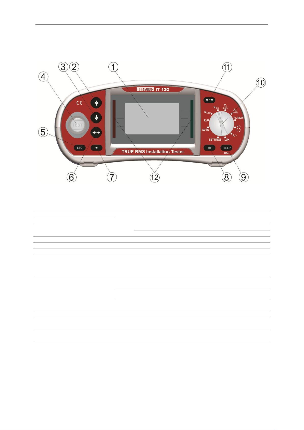
1
LCD
128 x 64 dots matrix display with backlight.
2
UP
Modifies selected parameter.
3
DOWN
4
TEST
Starts measurements.
Acts also as the PE touching electrode.
5
ESC
Goes one level back.
6
TAB
Selects the parameters in selected function.
7
Backlight, Contrast
Changes backlight level and contrast.
8
ON/OFF
Switches the instrument power on or off.
The instrument automatically turns off 15 minutes after
the last key was pressed.
9
HELP/CAL
Help function with connection diagrams
(press for approx. 2 seconds for R LOW and ΔU)
For calibrating the test cables in the R LOW and
CONTINUITY function
Starts the Z
REF
measurement in the sub-function
ΔU voltage drop
10
Function selector switch
Selects test function.
11
MEM
Stores / recalls memory of instrument.
Stores the settings of the current clamp adapter
12
Green LEDs
Red LEDs
Indicates PASS / FAIL of result.
1.2 Front and connector panel
Legend:
- 5 -
BENNING IT 130 short instructions
1
Test connector
Measuring inputs / outputs.
2
Charger socket
For charging the rechargeable Ni-MH storage batteries
3
USB connector
USB interface for PC connection
4
Protection cover
5
C1
Measuring input for optional current clamp adapter BENNING CC 1 /
BENNING CC 2 / BENNING CC 3
6
PS/2 connector
Serial RS-232 interface for PC connection
Connection for optional measuring adapters, e.g. BENNING luxmeter
type B
Connection for optional barcode scanner
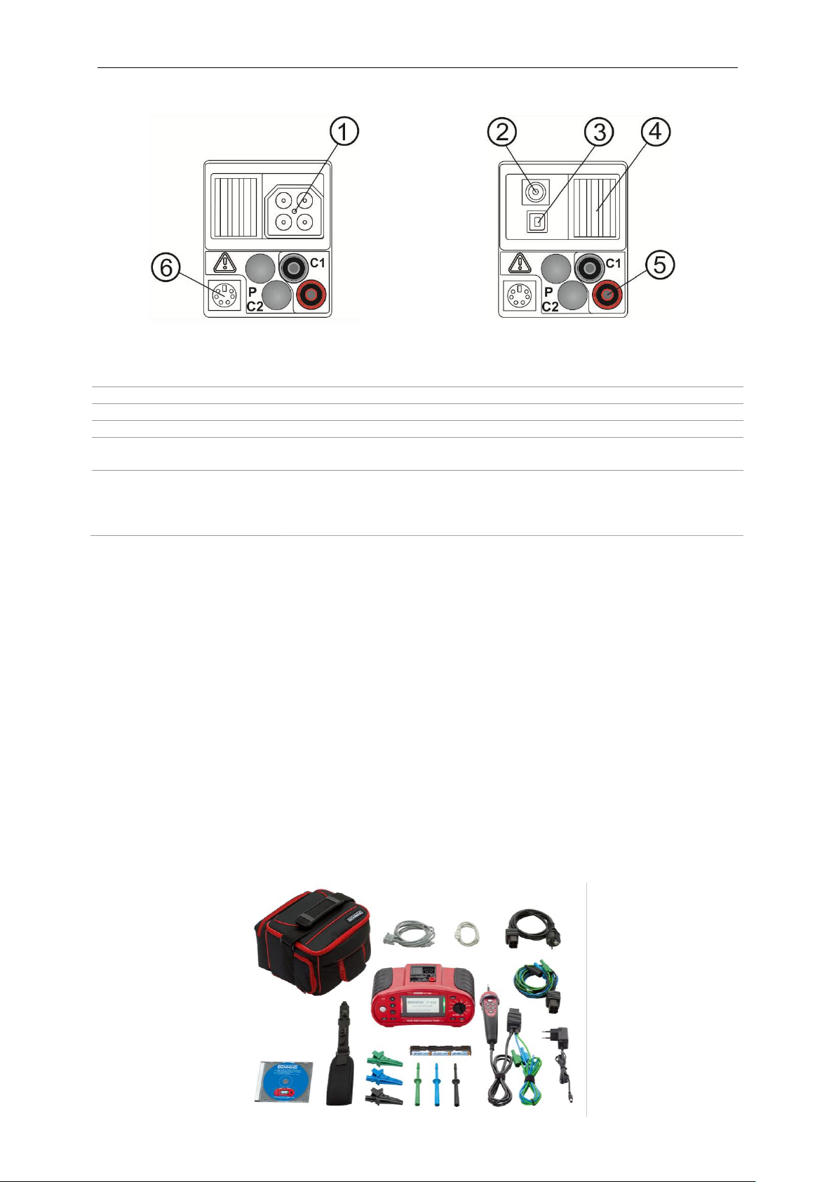
Legend:
1.3 Standard scope of delivery
1 x BENNING IT 130 installation tester
1 x padded carrying case
1 x "Commander" probe tip (switchable by means of TEST key)
1 x test cable with shock-proof plug
1 x universal three-wire test cable (black, blue, green)
1 x set of probe tips (black, blue, green)
1 x set of alligator clips (black, blue, green)
1 x carrying strap
1 x RS 232-PS/2 interface cable
1 x USB interface cable
6 x rechargeable NiMH storage batteries of size AA
2 x batteries of size AAA
1 x charger
1 x CD-ROM with BENNING PC-WIN IT 130 logging software and detailed operating manual
in PDF format
1 x printed brief operating manual
1 x calibration certificate
- 6 -
BENNING IT 130 short instructions
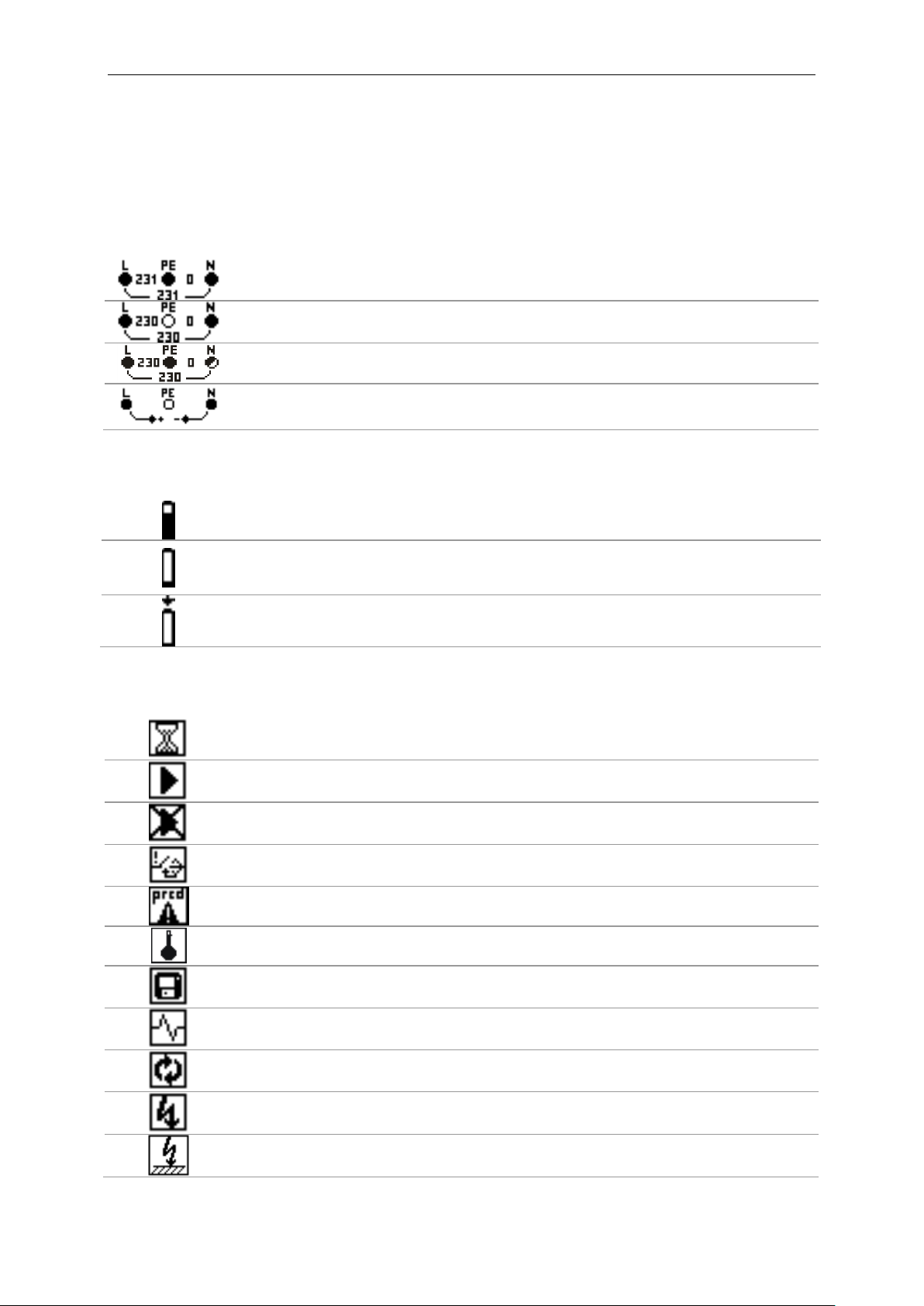
The voltage applied is displayed by means of the testing terminal symbol. All three
testing terminals L, N and PE are used for the selected measurement.
The voltage applied is displayed by means of the testing terminal symbol. The
testing terminals L and N are used for the selected measurement.
The testing terminals L and PE are active testing terminals. The testing terminal N
should be connected as well in order to have a correct input voltage.
The polarity of the testing voltage applied (R LOW, R ISO) is displayed at the
output terminals L and N.
Battery capacity indication.
Low battery.
The storage battery charge condition is too low to ensure correct measuring results.
Recharge the storage batteries or replace the batteries.
Charging in progress (if power supply adapter is connected).
Measurement is running, consider displayed warnings.
Conditions on the input terminals allow starting the measurement; consider other
displayed warnings and messages.
Conditions on the input terminals do not allow starting the measurement, consider
displayed warnings and messages.
RCD tripped-out during the measurement (in RCD functions).
Portable RCD selected (PRCD).
Instrument is overheated. The measurement is prohibited until the temperature
decreases under the allowed limit.
Result(s) can be stored.
High electrical noise was detected during measurement. Results may be impaired.
L and N are changed.
Warning! High voltage is applied to the test terminals.
Warning! Dangerous voltage on the PE terminal! Stop the activity immediately and
eliminate the fault / connection problem before proceeding with any activity!
1.4 Indications and meaning of symbols
Terminal voltage monitor
The terminal voltage monitor displays on-line the voltages on the test terminals and information about
active test terminals in the AC installation measuring mode.
Battery indication
Messages
- 7 -
 Loading...