

690
1000
1000
D
D
Bedienungsanleitung
Bedienungsanleitung
Operating manual
Operating manual
F
F
Mode d‘emploi
Mode d‘emploi
E
E
Manuel de instrucciones
Manuel de instrucciones
Инструкция за експлоатация
Инструкция за експлоатация
Návod k použití zkoušečky
Návod k použití zkoušečky
Betjeningsvejledning
Betjeningsvejledning
Käyttöohje
Käyttöohje
Οδηγίες χρήσεως
Οδηγίες χρήσεως
H
H
Használati utasítás
Használati utasítás
I
I
Istruzioni per l’uso
Istruzioni per l’uso
1000
®
T.-Nr. 10017909/ 06-2010
DUSPOL
BENNING Elektrotechnik & Elektronik GmbH & Co.KG
Münsterstraße 135 - 137 • D - 46397 Bocholt
Telefon ++49 (0) 2871 - 93 - 0 • Fax ++49 (0) 2871 - 93 - 429
www.benning.de • E-Mail: duspol@benning.de
Naudojimosi instrukcija
Naudojimosi instrukcija
N
N
Bruksanvisning
Bruksanvisning
Gebruiksaanwijzing
Gebruiksaanwijzing
Instrukcja obsługi
Instrukcja obsługi
Instrucţiuni de Utilizare
Instrucţiuni de Utilizare
Инструкция по
Инструкция по
эксплуатации
эксплуатации
напряжения
напряжения
S
S
Bruksanvisning
Bruksanvisning
Kullanma Talimati
Kullanma Talimati
Priručnik za upotrebu
Priručnik za upotrebu
geprüft und zugelassen
индикатора
индикатора
D
Operating manual
DUSPOL® 1000
Before using the voltage tester DUSPOL® 1000:
Please read the operating manual carefully and
always observe the safety instructions!
List of contents:
1. Safety instructions
2.
Functional description of the voltage tester
3. Functional test of the voltage tester
4. How to test AC voltages
4.1 How to test the phase at AC voltage
5. How to test DC voltages
5.1 How to test the polarity at DC voltage
6. How to test the phase sequence of a threephase mains
7. Technical data
8. General maintenance
9. Environmental notice
1. Safety instructions:
- Hold the voltage tester only by the insulated
handles A and B and do not touch the contact
electrodes (probe tips) !
- Immediately before use: Check the voltage tester
for correct operation! (see chapter 3). The voltage
tester must not be used if one or several display
functions fail or if the voltage tester is not ready to
operate (IEC 61243-3)!
- The voltage tester must be used only within the
nominal voltage range of 12 V up to AC/ DC
1000 V!
- The voltage tester complies with protection class
IP 64 and therefore can also be used under wet
conditions (designed for outdoor use).
- For testing, firmly grasp the voltage tester by the
handles A and B.
- Never connect the voltage tester to voltage for
longer than 30 seconds (maximum permissible
operating time = 30 s)!
- The voltage tester only operates correctly
within the temperature range of -10 °C up to
+55 °C at relative air humidity of 20 % up to 96 %.
- Do not dismantle the voltage tester!
- Please protect the housing of the voltage tester
against contamination and damages!
- Please store the voltage tester under dry
conditions.
- To prevent injuries provide the contact electrodes
(probe tips) with the enclosed cover after using the
voltage tester!
Attention:
After maximum load (i.e. after a measurement of 30
seconds at AC/ DC 1000 V), the voltage tester must
not be used for a duration of 240 seconds!
The voltage tester is marked with international electric
symbols and symbols for indication and operation with
the following meaning:
symbol meaning
Device or equipment for working under
voltage
Push button
Alternating current (AC)
Direct current (DC)
Direct and alternating current (DC
and AC)
Push button (manually actuated);
indicates that respective indications
only occur when both push buttons are
actuated
Phase-sequence clockwise
Phase-sequence indication; the phase
sequence can only be indicated at 50
or 60 Hz and in a earthed mains
Symbol for phase and phase-sequence
indication (phase-sequence clockwise)
2. Functional description
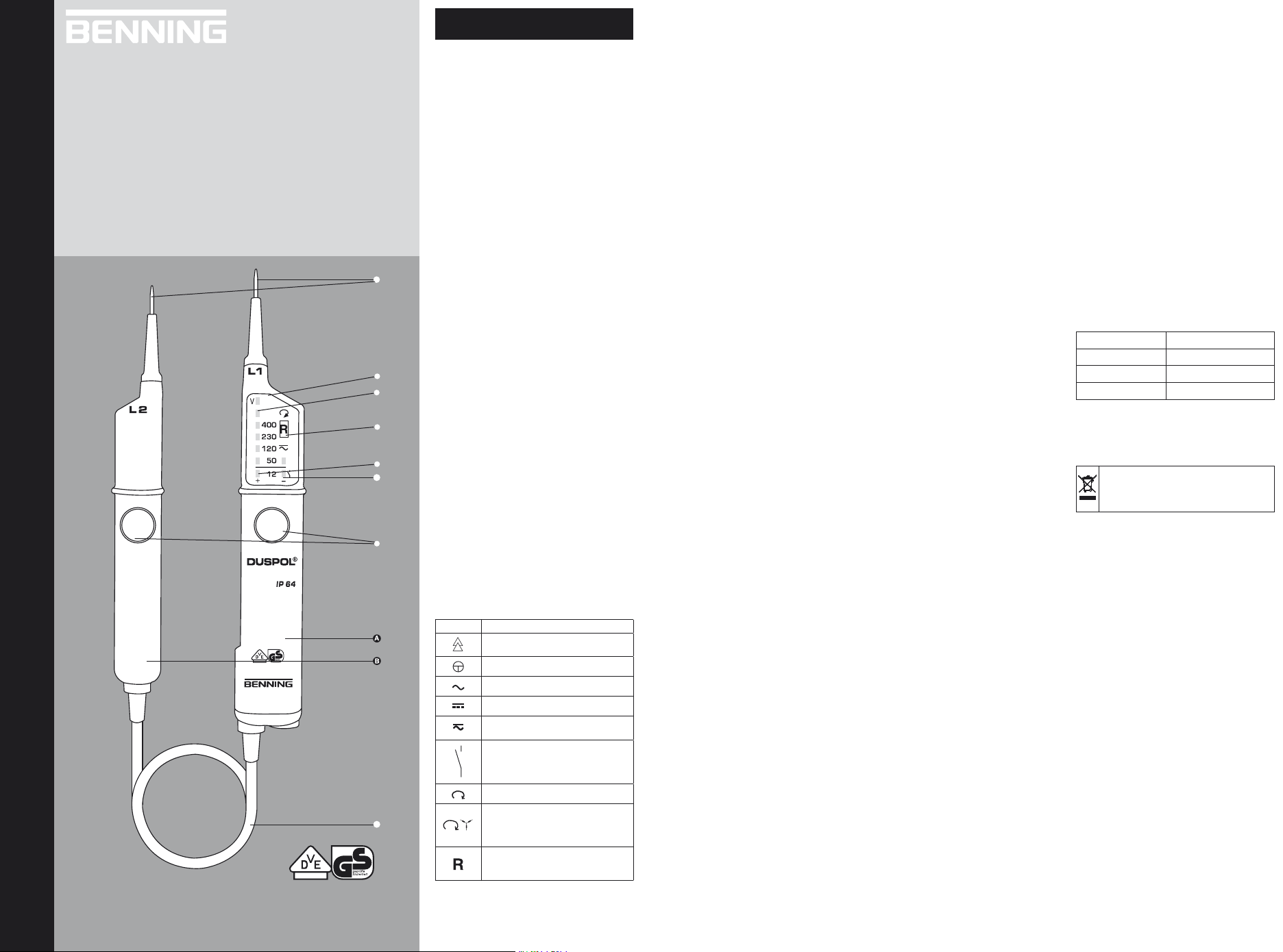
The DUSPOL® 1000 is a two-pole voltage tester
according to IEC 61243-3 with visual display
and without own power supply. The voltage tester
is designed for DC and AC voltage tests within the
voltage range of 12 V up to AC/ DC 1000 V. It can be
used to perform polarity tests in DC and phase tests in
AC. The voltage tester indicates the phase-sequence
provided that the neutral is earthed.
The voltage tester consists of the test probes L1 A
and L2 B and a connecting cable . The test probe
L1 A is equipped with a display . Both test probes
are provided with push buttons . Without pressing
both push buttons, the following voltage steps (AC
or DC) can be indicated: 50 V+; 50 V-; 120 V; 230 V;
400 V; 690 V; 1000 V.
By pressing both push buttons, the voltage tester
switches to a lower internal resistance (suppression
of inductive and capacitive voltages). Thus, also
the indication of 12 V+ and 12 V– is activated.
Furthermore, a vibrating motor (motor with a flyweight)
is put under voltage. From approximately 200 V this
motor is set in rotation. With the voltage increasing,
the motor’s speed and vibration increases as well so
that additionally by means of the handle of test probe
L2 B the voltage value can be estimated roughly
(e.g. 230/ 400 V). The duration of the test with a lower
internal resistance of the device (load test) depends
on the value of the voltage to be measured. To prevent
excessive warming of the voltage tester, it is equipped
with a thermal protection (reverse control). With this
reverse control, the speed of the vibrating motor
decreases as well.
Display field
The display system consists of high-contrast lightemitting diodes (LED) indicating DC and AC voltages
in steps of 12 V; 50 V; 120 V; 230 V; 400 V; 690 V
1000 V . The indicated voltages are nominal voltages.
With DC voltage, the LEDs also indicate the polarity for
12 V and 50 V (see chapter 5). The 12 V LED can only
be activated by pressing both push buttons.
LC display
The LC display serves for the phase test with
alternating current (AC) and indicates the phasesequence of a three-phase mains.
3. Functional check
- The voltage tester must be used only within
the nominal voltage range of 12 V up to
AC/ DC 1000 V!
- Never connect the voltage tester to voltage for
longer than 30 seconds (maximum permissible
operating time = 30 s)!
- Check the voltage tester for correct function
immediately before use!
- Test all functions by means of known voltage
sources.
• For DC voltage tests use e.g. a car battery.
• For AC voltage tests use e.g. a 230 V socket.
Do not use the voltage tester unless all functions are
operating correctly!
Check the function of the LC display by single-pole
connection of the contact electrode of the test probe
L1 A to an external conductor (phase).
4. How to test AC voltages
- The voltage tester must be used only within the
nominal voltage range of 12 V up to AC 1000 V!
- Never connect the voltage tester to voltage for
longer than 30 seconds (maximum permissible
operating time = 30 s)!
- Firmly grasp the insulated handles A and B of
the test probes L1 and L2.
- Place the contact electrodes of the test probes
L1 A and L2 B against the relevant points of the
unit under test.
- For AC voltages from 50 V onwards and when
pressing both push buttons (load test) from 12 V
onwards, the LEDs “plus” and “minus” and
light up. Furthermore, all LEDs light until the step
value of the applied voltage is reached.
- When pressing both push buttons and from
an applied voltage of approx. 200 V onwards, a
vibrating motor is put in rotation inside the test
probe L2 B. With the voltage increasing, the
speed of this motor is increasing as well.
Please make sure that you touch the voltage tester at
the insulated handles of test probes L1 A and L2 B
only! Do not cover the display and do not touch the
contact electrodes !
4.1 How to test the phase at AC voltage
- The voltage tester must be used only within the
nominal voltage range of 12 V up to AC 1000 V!
- The phase test is possible in the earthed mains
from 230 V onwards!
- Firmly grasp the handle of test probe L1 A.
- Place the contact electrode of test probe L1 A
against the relevant point of the unit under test.
- Never connect the voltage tester to voltage for
longer than 30 seconds (maximum permissible
operating time = 30 s)!
- If the “R” symbol appears on the LC display ,
the tester is in contact with the live phase of an
AC voltage on this point of the unit under test.
Never touch the contact electrode of test probe L2 B
during the single-pole test (phase test)!
Note:
The reading of the LC display might be impaired
due to unfavorable light conditions, protective clothing
or in insulated locations.
Attention:
The absence of voltage can be detected by means of
a bipolar test only.
5. How to test DC voltages
-
The voltage tester must be used only within the
nominal voltage range of 12 V up to DC 1000 V!
- Never connect the voltage tester to voltage for
longer than 30 seconds (maximum permissible
operating time = 30 s)!
- Firmly grasp the insulated handles A and B of
the test probes L1 and L2.
- Place the contact electrodes of the test probes
L1 A and L2 B against the relevant points of the
unit under test.
- For AC voltages from 50 V onwards and when
pressing both push buttons (load test) from 12 V
onwards, the LEDs “plus” and “minus” and
light up. Furthermore, all LEDs light until the step
value of the applied voltage is reached.
- When pressing both push buttons and from
an applied voltage of approx. 200 V onwards, a
vibrating motor is put in rotation inside the test
probe L2 B. With the voltage increasing, the
speed of this motor is increasing as well.
Please make sure that you touch the voltage tester at
the insulated handles of test probes L1 A and L2 B
only! Do not cover the display and do not touch the
contact electrodes!
5.1 How to test the polarity at DC voltage
- The voltage tester must be used only within the
nominal voltage range of 12 V up to DC 1000 V!
- Never connect the voltage tester to voltage for
longer than 30 seconds (maximum permissible
operating time = 30 s)!
- Firmly grasp the insulated handles A and B of
the test probes L1 and L2.
- Place the contact electrodes of the test probes
L1 A and L2 B against the relevant points of the
unit under test.
- If LED lights up, the “positive pole” of the unit
under test is at test probe A.
- If LED lights up, the “negative pole” of the unit
under test is at test probe A.
Please make sure that you touch the voltage tester at
the insulated handles of test probes L1 A and L2 B
only! Do not cover the display and do not touch the
contact electrodes!
6. How to test the phase sequence of a three-
phase mains
- The voltage tester must be used only within the
nominal voltage range of 12 V up to AC 1000 V!
- The phase-sequence test is possible from 230 V
AC voltage (phase against phase) onwards in a
earthed three-phase mains.
- Firmly grasp the insulated handles A and B of
the test probes L1 and L2.
- Place the contact electrodes of the test probes
L1 A and L2 B against the relevant points of the
unit under test.
- The LEDs have to indicate the external conductor
voltage.
- Never connect the voltage tester to voltage for
longer than 30 seconds (maximum permissible
operating time = 30 s)!
- When contacting the two contact electrodes
with two phases of a three-phase mains connected
in clockwise rotation, the LC display indicates
the “R” symbol. If for two phases the rotation is
anti-clockwise, no symbol appears on the LC
display.
The phase-sequence test always requires a countertest! If the LC display indicates clockwise rotation
for two phases of a three-phase mains, those two
phases must be contacted again with reversed contact
electrodes during the counter-test. There must
be no symbol indicated on the LC display during
the counter-test. If in both cases the LC display
indicates the “R” symbol, the earthing is too weak!
Note:
The reading of the LC display might be impaired
due to unfavorable light conditions, protective clothing
or in insulated locations.
7. Technical data:
-
Guideline for two-pole voltage testers: IEC 61243-3,
-
Over voltage category: CAT IV 1000 V
- Protection class: IP 64, IEC 60529 (DIN 40050)
IP 64 means: Protection against access to
dangerous parts and protection against solid
impurities, dustproof, (6 - first index). Splash proof,
(4 - second index). Can also be used in case of
precipitation.
-
Nominal voltage range: 12 V to AC/ 1000 V
- Internal resistance, measuring circuit: 300 kΩ,
- Internal resistance, load circuit – both push
buttons actuated!: approx. 3.7 kΩ...(150 kΩ)
- Current consumption, measuring circuit:
max. In 3.5 mA (1000 V ) AC/ 3.4 mA (1000 V) DC
- Current consumption, load circuit – both push
buttons actuated!: I
- Polarity indication: LED +; LED -
(indicating handle = positive polarity)
- Indicating steps LED: 12 V+*, 12 V-*, 50 V+, 50 V-,
50 V, 120 V, 230 V, 400 V 690 V and 1000 V
(*: only with both push buttons actuated)
- max. indicating errors: Un ± 15 %, ELV Un - 15 %
- Nominal frequency range f: 0 to 500 Hz
Phase and phase-sequence indication 50/ 60 Hz
- Phase and phase-sequence indication: ≥ Un 230 V
- Vibrating motor, starting: ≥ Un 230 V
- max. permissible operating time: ED = 30 s (max.
30 seconds), 240 s pause
- Weight: approx. 160 g
- Connecting cable length: approx. 900 mm
- Operating and storing temperature range: -10 °C
to +55 °C (climate category N)
- Relative air humidity: 20 % to 96 % (climate
category N)
- Reverse control times (thermal protection):
voltage time
230 V 30 s
400 V 9 s
1000 V 2 s
8. General maintenance:
Clean the exterior of the housing with a clean dry
cloth (exception: special cleansing cloths). Do not use
solvents and/or abrasives to clean the voltage tester.
9. Environmental notice
At the end of the product’s useful life, please
dispose of it at appropriate collection points
provided in your country.
0.37 A (1000 V)
s
 Loading...