

BENNING BENNING MM 6-2 Instructions

D
Bedienungsanleitung
Operating manual
F
Notice d‘emploi
E
Instrucciones de servicio
Návod k obsluze
Οδηγίες χρήσεως
I
Istruzioni d’uso
Gebruiksaanwijzing
Instrukcja obsługi
Инструкция по эксплуатации
индикатора напряжения
Kullanma Talimati
VoltSense
MM 6-2
BENNING MM 6-1/ MM 6-2
AutoV
LoZ
Lo/Hi
RANGE
∆/PEAK HOLD
Sense
600V CAT IV
1000V CAT III
Volt

D F E I
VoltSense
AutoV
MM 6-1
Lo/Hi°C / °F
RANGE
∆/PEAK HOLD
Volt
LoZ
Sense
N
8
M
VoltSense
600V CAT IV
1000V CAT III
MM 6-2
Lo/Hi
RANGE
∆/PEAK HOLD
Volt
AutoV
LoZ
L
Bild 1: Gerätefrontseite
Fig. 1: Front tester panel
Fig. 1: Panneau avant de l‘appareil
Fig. 1: Parte frontal del equipo
Obr. 1: Přední strana přístroje
σχήμα 1: Μπροστινή όψη
ill. 1: Lato anteriore apparecchio
3
02/ 2016
BENNING MM 6-1/ 6-2
Sense
600V CAT IV
1000V CAT III
Fig. 1: Voorzijde van het apparaat
Rys.1: Panel przedni przyrządu
Рис. 1. Фронтальная сторона прибора
Resim 1: Cihaz ön yüzü

D F E I
VoltSense
MM 6-2
Lo/Hi
RANGE
∆/PEAK HOLD
Volt
AutoV
LoZ
Bild 2: Gleichspannungsmessung
Fig. 2: Direct voltage measurement
Fig. 2: Mesure de tension continue
Fig. 2: Medición de tension contínua
Obr. 2: Měření stejnosměrného napětí
σχήμα 2: μέτρηση DC-τάσης
ill. 2: Misura tensione continua
Fig. 2: Meten van gelijkspanning
Rys.2: Pomiar napięcia stałego
Рис. 2. Измерение напряжения постоянного тока
Resim 2: Doğru Gerilim Ölçümü
Sense
600V CAT IV
1000V CAT III
VoltSense
MM 6-2
VoltSense
MM 6-2
Lo/Hi
RANGE
∆/PEAK HOLD
Volt
AutoV
LoZ
Bild 3: Wechselspannungsmessung
Fig. 3: Alternating voltage measurement
Fig. 3: Mesure de tension alternative
Fig. 3: Medición de tensión alterna
Obr. 3: Měření střídavého napětí
σχήμα 3: μέτρηση AC-τάσης
ill. 3: Misura tensione alternata
Fig. 3: Meten van wisselspanning
Rys.3: Pomiar napięcia przemiennego
Рис. 3. Измерение напряжения переменного тока
Resim 3: Alternatif Gerilim Ölçümü
Sense
600V CAT IV
1000V CAT III
VoltSense
MM 6-2
Lo/Hi
RANGE
∆/PEAK HOLD
Volt
AutoV
LoZ
BENNING MM 6-2
Bild 4: Gleichstrommessung
Fig. 4: DC current measurement
Fig. 4: Mesure de courant continu
Fig. 4: Medición de corriente contínua
Obr. 4: Měření stejnosměrného proudu
σχήμα 4: μέτρηση συνεχούς ρεύματος
ill. 4: Misura corrente continua
Fig. 4: Meten van gelijkstroom
Rys.4: Pomiar prądu stałego
Рис. 4. Измерение постоянного тока
Resim 4: Doğru Akım Ölçümü
4
02/ 2016
Sense
600V CAT IV
1000V CAT III
BENNING MM 6-1/ 6-2
BENNING MM 6-2
Bild 5: Wechselstrommessung
Fig. 5: AC current measurement
Fig. 5: Mesure de courant alternatif
Fig. 5: Medición de corriente alterna
Obr. 5: Měření střídavého proudu
σχήμα 5: AC- μέτρηση
ill. 5: Misura corrente alternata
Fig. 5: Meten van wisselstroom
Rys.5: Pomiar prądu przemiennego
Рис. 5. Измерение переменного тока
Resim 5: Alternatif Akım Ölçümü
Lo/Hi
RANGE
∆/PEAK HOLD
Volt
600V CAT IV
1000V CAT III
Sense
AutoV
LoZ

D F E I
VoltSense
MM 6-2
Lo/Hi
RANGE
∆/PEAK HOLD
Volt
AutoV
LoZ
Bild 6: Widerstandsmessung
Fig. 6: Resistance measurement
Fig. 6: Mesure de résistance
Fig. 6: Medición de resistencia
Obr. 6: Měření odporu
σχήμα 6: Μέτρηση αντίστασης
ill. 6: Misura di resistenza
Fig. 6: Weerstandsmeting
Rys.6: Pomiar rezystancji
Рис. 6. Измерение сопротивления
Resim 6: Direnç Ölçümü
Sense
600V CAT IV
1000V CAT III
VoltSense
MM 6-2
VoltSense
MM 6-2
Lo/Hi
RANGE
∆/PEAK HOLD
Volt
AutoV
LoZ
Bild 7: Diodenprüfung
Fig. 7: Diode Testing
Fig. 7: Contrôle de diodes
Fig. 7: Verificación de diodos
Obr. 7: Zkouška diod
σχήμα 7: Έλεγχος διόδου
ill. 7: Prova diodi
Fig. 7: Diodecontrole
Rys.7: Pomiar diody
Рис. 7. Проверка диодов
Resim 7: Diyot Kontrolü
Sense
600V CAT IV
1000V CAT III
VoltSense
MM 6-2
Lo/Hi
RANGE
∆/PEAK HOLD
Volt
AutoV
LoZ
Bild 8: Durchgangsprüfung mit Summer
Fig. 8: Continuity Testing with buzzer
Fig. 8: Contrôle de continuité avec ronfleur
Fig. 8: Control de continuidad con vibrador
Obr. 8: Zkouška průchodu proudu se bzučákem
σχήμα 8: Έλεγχος συνέχειας με ηχητικό σήμα
ill. 8: Prova di continuità con cicalino
Fig. 8: Doorgangstest met akoestisch signaal
Rys.8: Sprawdzenie ciągłości obwodu
Рис. 8. Контроль прохождения тока с зуммером
Resim 8: Sesli Uyarıcı ile Süreklilik kontrolü
5
02/ 2016
Sense
600V CAT IV
1000V CAT III
BENNING MM 6-1/ 6-2
Bild 9: Kapazitätsmessung
Fig. 9: Capacity Testing
Fig. 9: Mesure de capacité
Fig. 9: Medición de capacidad
Obr. 9: Měření kapacity
σχήμα 9: Μέτρηση χωρητικότητας
ill. 9: Misura di capacità
Fig. 9: Capaciteitsmeting
Rys.9: Pomiar pojemności
Рис. 9. Измерение емкости
Resim 9: Kapasite Ölçümü
Lo/Hi
RANGE
∆/PEAK HOLD
Volt
600V CAT IV
1000V CAT III
Sense
AutoV
LoZ

D F E I
VoltSense
MM 6-2
Lo/Hi
RANGE
∆/PEAK HOLD
Volt
1000V CAT III
Sense
600V CAT IV
VoltSense
MM 6-2
AutoV
LoZ
Bild 10: Frequenzmessung
Fig. 10: Frequency measurement
Fig. 10: Mesure de fréquence
Fig. 10: Medición de frecuencia
Obr. 10: Měření kmitočtu
σχήμα 10: Μέτρηση συχνότητας
ill. 10: Misura di frequenza
Fig. 10: Frequentiemeting
Rys.10: Pomiar częstotliwości
Рис. 10. Измерение частоты
Resim 10: Frekans Ölçümü
VoltSense
MM 6-1
Lo/Hi°C / °F
RANGE
∆/PEAK HOLD
Volt
600V CAT IV
1000V CAT III
Sense
AutoV
LoZ
BENNING MM 6-1
Bild 11: Temperaturmessung
Fig. 11: Temperature measurement
Fig. 11: Mesure de température
Fig. 11: Medición de temperatura
Obr. 11: Měření teploty
σχήμα 11: Μέτρηση θερμοκρασίας
ill. 11: Misura di temperatura
Fig. 11: Meten van temperatuur
Rys.11: Pomiar temperatury
Рис. 11. Измерение температуры
Resim 11: Isı Ölçümü
Lo/Hi
RANGE
∆/PEAK HOLD
Volt
AutoV
LoZ
Bild 12: Spannungsindikator mit Summer
Fig. 12: Voltage indicator with buzzer
Fig. 12: Indicateur de tension avec ronfleur
Fig 12: indicador de tensión con vibrador
Obr. 12: Indikátor napětí s bzučákem
εικόνα 12: Ένδειξη τάσης με βομβητή
ill. 12: Indicatore di tensione con cicalino
Fig. 12: Spanningsindicator met zoemer
Rys. 12: Wskaźnik napięcia z sygnalizacja
dźwiękową
рис. 12: Индикатор напряжения с зуммером
Resim 12: Akustik gerilim indikatörü
6
02/ 2016
Sense
600V CAT IV
1000V CAT III
Bild 13: Batteriewechsel
Fig. 13: Battery replacement
Fig. 13: Remplacement de la pile
Fig. 13: Cambio de pila
Obr. 13: Výměna baterií
σχήμα 13: Αντικατάσταση μπαταριών
ill. 13: Sostituzione batterie
Fig. 13: Vervanging van de batterijen
Rys.13: Wymiana baterii
Рис. 13. Замена батарейки
Resim 13: Batarya Değişimi
BENNING MM 6-1/ 6-2

D F E I
BENNING MM 6-2
Bild 14: Sicherungswechsel
Fig. 14: Fuse replacement
Fig. 14: Remplacement des fusibles
Fig. 14: Cambio de fusible
Obr. 14: Výměna pojistek
σχήμα 14: αντικατάσταση μπαταρίας
ill. 14: Sostituzione fusibile
Fig. 14: Vervanging van de smeltzekeringen
Rys.14: Wymiana bezpiecznika
Рис. 14. Замена предохранителя
Resim 14: Sigorta Değişimi
Bild 16: Aufstellung des BENNING MM 6-1/ MM 6-2
Fig. 16: Standing up the BENNING MM 6-1/ MM 6-2
Fig. 16: Installation du BENNING MM 6-1/ MM 6-2
Fig. 16: Colocación del BENNING MM 6-1/ MM 6-2
Obr. 16: Postavení přístroje BENNING MM 6-1/ MM 6-2
σχήμα 16: Κρατώντας όρθιο το BENNING MM 6-1/ MM 6-2
ill. 16: Posizionamento del BENNING MM 6-1/ MM 6-2
Fig. 16: Opstelling van de multimeter BENNING MM 6-1/ MM 6-2
Rys.16: Przyrząd BENNING MM 6-1/ MM 6-2 w pozycji stojącej
Рис. 16. Установка прибора BENNING MM 6-1/ MM 6-2
Res.16: BENNING MM 6-1/ MM 6-2’nin kurulumu
Bild 15: Aufwicklung der Sicherheitsmessleitung
Fig. 15: Winding up the safety measuring leads
Fig. 15: Enroulement du câble de mesure de sécurité
Fig. 15: Arrollamiento de la conducción protegida de
Obr. 15: Navíjení bezpečnostního kabelu měřicího
σχήμα 15: Τυλίξτε τα καλώδια μέτρησης
ill. 15: Avvolgimento dei cavetti di sicurezza
Fig. 15: Wikkeling van veiligheidsmeetsnoeren
Rys.15: Zwijanie przewodów pomiarowych
Рис. 15. Намотка безопасного измерительного
Res.15: Emniyet Ölçüm Tesisatının Sarılması
medición
obvodu
провода
7
02/ 2016
BENNING MM 6-1/ 6-2

D
Bedienungsanleitung
BENNING MM 6-1/ MM 6-2
Digital-Multimeter zur
- Gleichspannungsmessung
- Wechselspannungsmessung
- Gleichstrommessung
- Wechselstrommessung
- Widerstandsmessung
- Diodenprüfung
- Durchgangsprüfung
- Kapazitätsmessung
- Frequenzmessung
- Temperaturmessung (BENNING MM 6-1)
Inhaltsverzeichnis
1. Benutzerhinweise
2. Sicherheitshinweise
3. Lieferumfang
4. Gerätebeschreibung
5. Allgemeine Angaben
6. Umgebungsbedingungen
7. Elektrische Angaben
8. Messen mit dem BENNING MM 6-1/ MM 6-2
9. Instandhaltung
10. Anwendung des Gummi-Schutzrahmens
11. Technische Daten des Messzubehörs
12. Umweltschutz
1. Benutzerhinweise
Diese Bedienungsanleitung richtet sich an
- Elektrofachkräfte und
- elektrotechnisch unterwiesene Personen
Das BENNING MM 6-1/ MM 6-2 ist zur Messung in trockener Umgebung
vorgesehen. Es darf nicht in Stromkreisen mit einer höheren Nennspannung
als 1000 V DC/ AC eingesetzt werden (Näheres hierzu im Abschnitt 6. “Um gebungs bedingungen”).
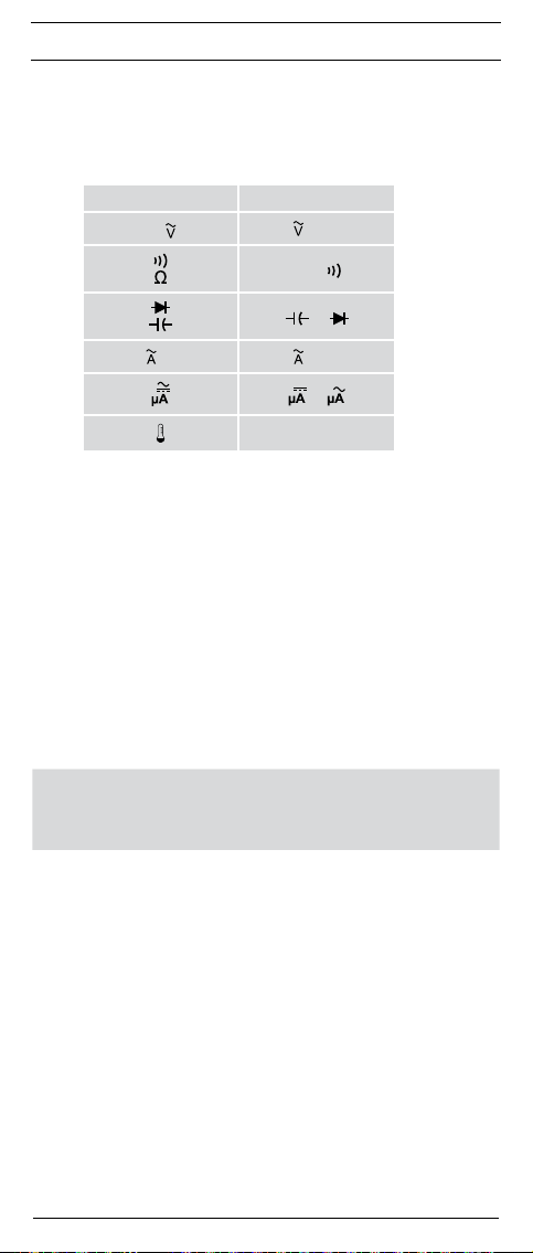
In der Bedienungsanleitung und auf dem BENNING MM 6-1/ MM 6-2 werden
folgende Symbole verwendet:
Warnung vor elektrischer Gefahr!
Steht vor Hinweisen, die beachtet werden müssen, um Gefahren für
Menschen zu vermeiden.
Achtung Dokumentation beachten!
Das Symbol gibt an, dass die Hinweise in der Bedienungsanleitung
zu beachten sind, um Gefahren zu vermeiden.
Dieses Symbol auf dem BENNING MM 6-1/ MM 6-2 bedeutet, dass
das BENNING MM 6-1/ MM 6-2 schutzisoliert (Schutzklasse II)
ausgeführt ist.
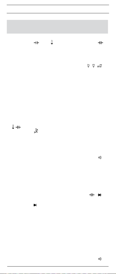
Dieses Symbol auf dem BENNING MM 6-2 weist auf die ein ge baute
Sicherung hin.
Dieses Symbol auf dem BENNING MM 6-1/ MM 6-2 bedeutet, dass
das BENNING MM 6-1/ MM 6-2 konform zu den EU-Richtlinien ist.
Dieses Symbol erscheint in der Anzeige für eine entladene Batterie.
Dieses Symbol kennzeichnet den Bereich “Durchgangsprüfung”.Der
Summer dient der akustischen Er geb nis aus gabe.
Dieses Symbol kennzeichnet den Bereich „Diodenprüfung“.
Dieses Symbol kennzeichnet den Bereich “Kapazitätsprüfung”.
(DC) Gleich- Spannung oder Strom.
(AC) Wechsel- Spannung oder Strom.
Erde (Spannung gegen Erde).
8
02/ 2016
BENNING MM 6-1/ 6-2

D
2. Sicherheitshinweise
Das Gerät ist gemäß
DIN VDE 0411 Teil 1/EN 61010-1
DIN VDE 0411 Teil 2-033/EN 61010-2-033
DIN VDE 0411 Teil 031/EN 61010-031 gebaut und geprüft und hat das Werk in
einem sicherheitstechnisch einwandfreien Zustand verlassen.
Um diesen Zustand zu erhalten und einen gefahrlosen Betrieb sicherzustellen,
muss der Anwender die Hinweise und Warnvermerke beachten die in dieser
Anleitung enthalten sind. Fehlverhalten und Nichtbeachtung der Warnungen
kann zu schwerwiegenden Verletzungen oder zum Tode führen.
Extreme Vorsicht bei Arbeiten um blanke Leiter oder Hauptleitungsträger. Ein Kontakt mit Leitern kann einen Elektro-
schock verursachen.
Das BENNING MM 6-1/ MM 6-2 darf nur in Stromkreisen der
Überspannungskategorie III mit max. 1000 V Leiter oder
Überspannungskategorie IV mit max. 600 V Leiter gegen Erde
benutzt werden.
Hierzu sind geeignete Messleitungen zu verwenden. Bei
Messungen innerhalb der Messkategorie III oder der Mess katego rie IV darf das hervorstehende leitfähige Teil einer Kon taktspitze der Messleitung nicht länger als 4 mm sein.
Vor Messungen innerhalb der Messkategorie III und der Mess-
kategorie IV müssen, die dem Set beigestellten, mit CAT III
und CAT IV gekennzeichneten, Aufsteckkappen auf die Kontakt spitzen aufgesteckt werden. Diese Maßnahme dient dem
Benutzerschutz.
Beachten Sie, dass Arbeiten an spannungsführenden Teilen
und Anlagen grundsätzlich gefährlich sind. Bereits Span nungen
ab 30 V AC und 60 V DC können für den Menschen lebensgefährlich sein.
Vor jeder Inbetriebnahme überprüfen Sie das Gerät und die
Leitungen auf Beschädigungen.
Ist anzunehmen, dass ein gefahrloser Betrieb nicht mehr möglich ist, ist das
Gerät außer Betrieb zu setzen und gegen unbeabsichtigten Betrieb zu sichern.
Es ist anzunehmen, dass ein gefahrloser Betrieb nicht mehr möglich ist,
-
wenn das Gerät oder die Messleitungen sichtbare Beschädigungen aufweisen,
- wenn das Gerät nicht mehr arbeitet,
- nach längerer Lagerung unter ungünstigen Verhältnissen,
- nach schweren Transportbeanspruchungen,
- wenn das Gerät oder die Messleitungen feucht sind.
Um eine Gefährdung auszuschließen
- berühren Sie die Leitungen nicht an den blanken Messspitzen,
- stecken Sie die Leitungen in die entsprechend gekennzeichneten
Buchsen am Multimeter
Reinigung:
Das Gehäuse regelmäßig mit einem Tuch und Reinigungsmittel
trocken abwischen. Kein Poliermittel oder Lösungsmittel verwenden.
3. Lieferumfang
Zum Lieferumfang des BENNING MM 6-1/ MM 6-2 gehören:
3.1 ein Stück BENNING MM 6-1/ MM 6-2,
3.2 ein Stück Sicherheitsmessleitung, rot (L = 1,4 m),
3.3 ein Stück Sicherheitsmessleitung, schwarz (L = 1,4 m),
3.4 ein Stück Drahttemperatursensor Typ K,(nur BENNING MM 6-1)
3.5 ein Stück Gummi-Schutzrahmen mit Magnethalter
3.6 ein Stück Kompakt-Schutztasche,
3.7 ein Stück 9-V-Blockbatterie ist zur Erstbestückung im Gerät eingebaut,
3.8 eine Sicherung ist zur Erstbestückung im Gerät eingebaut
(BENNING MM 6-2)
3.9 eine Bedienungsanleitung.
9
02/ 2016
BENNING MM 6-1/ 6-2

D
Hinweis auf optionales Zubehör:
- Temperaturfühler (K-Typ) aus V4A-Rohr
Anwendung: Einstichfühler für weichplastische Medien, Flüssigkeiten, Gas
und Luft
Messbereich: - 196 °C bis + 800 °C
Abmessungen: Länge = 210 mm, Rohrlänge = 120 mm, Rohrdurchmesser
= 3 mm, V4A (T.Nr. 044121)
Hinweis auf Verschleißteile:
- Das BENNING MM 6-2 enthält eine Sicherung zum Überlastschutz:
Ein Stück Sicherung Nennstrom 11 A flink (1000 V) 20 kA, D = 10,3 mm, L
= 38,1 mm (T.Nr. 10016656).
- Das BENNING MM 6-1/ MM 6-2 wird durch eine eingebaute 9-V-Block-
batterie (IEC 6 LR 61) gespeist.
- Die oben genannten Sicherheitsmessleitungen (geprüftes Zubehör) ent-
sprechen CAT III 1000 V/ CAT IV 600 V und sind für einen Strom von 10 A
zugelassen.
4. Gerätebeschreibung
siehe Bild 1: Gerätefrontseite
Die in Bild 1 angegebenen Anzeige- und Bedienelemente werden wie folgt
bezeichnet:
1
Digitalanzeige, für den Messwert, die Bargraphanzeige und die Anzeige der
Bereichs über schreitung,
2
Polaritätsanzeige,
3
Batterieanzeige,
4
Funktions-Taste (blau),
5
RANGE-Taste, Umschaltung automatischer/ manueller Messbereich,
6
Δ/PEAK-Taste, Relativwert-Funktion bzw. Spitzenwertspeicherung
7
Smart HOLD-Taste,
8
Taste (gelb), Displaybeleuchtung,
9
Drehschalter, für Wahl der Messfunktion,
Buchse (positive1), für V, Ω, , Hz, μA, (+) (BENNING MM 6-1) bzw. für
V, Ω, , Hz (BENNING MM 6-2)
COM-Buchse, gemeinsame Buchse für Strom-, Spannungs-, Widerstands-,
Frequenz-, Temperatur-, Kapazitätsmessungen, Durchgangs- und
Diodenprüfung,
L
Buchse (positive), für 10 A-Bereich, für Ströme bis 10 A,
M
Gummi-Schutzrahmen
N
LED (rot) für Spannungsindikator und Durchgangsprüfung
1) Hierauf bezieht sich die automatische Polaritätsanzeige für Gleichstrom- und Spannung
5. Allgemeine Angaben
5.1 Allgemeine Angaben zum Multimeter
5.1.1
Die Digitalanzeige 1 ist als 4-stellige Flüssigkristallanzeige mit 15 mm
Schrifthöhe mit Dezimalpunkt ausgeführt. Der größte Anzeigewert ist 6000.
5.1.2 Die Bargraphanzeige besteht aus 60 Segmenten.
5.1.3 Die Polaritätsanzeige 2 wirkt automatisch. Es wird nur eine Polung
entgegen der Buchsendefinition mit “-” angezeigt.
5.1.4 Die Bereichsüberschreitung wird mit „0L“ oder „- 0L“ und teilweise einer
akustischen Warnung angezeigt.
Achtung, keine Anzeige und Warnung bei Überlast!
5.1.5 Der Drehschalter 9 dient der Anwahl der Messfunktion.
5.1.6 Die Bereichstaste „RANGE“ 5 dient zur Weiterschaltung der manuellen
Messbereiche bei gleichzeitiger Ausblendung von „AUTO“ im Display.
Durch längeren Tastendruck (2 Sekunden) wird die automatische
Bereichswahl gewählt (Anzeige „AUTO“).
5.1.7 Die Δ/PEAK-Taste 6 (Relativwert-Funktion) speichert den aktuellen
Anzeigewert und zeigt die Differenz (Offset) zwischen dem gespeicherten Messwert und den folgenden Messwerten auf dem Display an. Wird
die Δ/PEAK-Taste 6 für ca. 2 Sekunden gedrückt, schaltet das Gerät
in die PEAK-Funktion (Spitzenwertspeicherung). Die PEAK-Funktion
erfasst und speichert den positiven und negativen Spitzen-/ Scheitelwert
(> 1 ms) in der Funktion mV, V AC/ DC und mA, A AC/ DC. Durch
Tastendruck kann der Pmax, Pmin und der aktuelle Messwert (Pmax,
Pmin) aufgerufen werden. Durch längeren Tastendruck (2 Sekunden)
wird in den Normalmodus zurückgeschaltet.
5.1.8 Messwertspeicherung „Smart HOLD“: Durch Betätigen der Taste „Smart
HOLD“ 7 lässt sich das Messergebnis speichern. Im Display 1 wird
gleichzeitig das Symbol „HOLD“ eingeblendet. Steigt der Messwert
um 50 Digit über dem gespeicherten Wert, wird die Messwertänderung
durch ein blinkendes Display und durch einen Signalton angezeigt.
(Messwertänderungen zwischen AC und DC Spannung/ Strom werden
10
02/ 2016
BENNING MM 6-1/ 6-2
D
nicht erkannt). Erneutes Betätigen der Taste schaltet in den Messmodus
zurück.
5.1.9 Taste (gelb) 8 schaltet die Beleuchtung des Displays an. Die
Ausschaltung erfolgt automatisch nach 2 Minuten oder durch erneute
Tastenbetätigung.
5.1.10 Die Funktions-Taste (blau) 4 wählt die Zweitfunktion der Dreh schal ter-
stellung.
Schalterstellung Funktion
Hz
Hz ► Hz
5.1.11 Die Messrate des BENNING MM 6-1/ MM 6-2 beträgt nominal 2 Mes-
sungen pro Sekunde für die Digitalanzeige.
5.1.12 Das BENNING MM 6-1/ MM 6-2 wird durch den Drehschalter 9 ein-
oder ausgeschaltet. Ausschaltstellung “OFF”.
5.1.13 Das BENNING MM 6-1/ MM 6-2 schaltet sich nach ca. 20 min selbsttä-
tig ab (APO, Auto-Power-Off). Es schaltet sich wieder ein, wenn eine
Taste betätigt wird.
Die automatische Abschaltung lässt sich deaktivieren indem
sie die Funktions-Taste (blau) 4 betätigen und gleichzeitig das
BENNING MM 6-1/ MM 6-2 aus der Schalterstellung „OFF“ einschalten.
5.1.14
Die Segmente der Digitalanzeige lassen sich überprüfen indem
sie die „Smart HOLD“-Taste 7 betätigen und gleichzeitig das
BENNING MM 6-1/ MM 6-2 aus der Schalterstellung „OFF“ einschalten.
5.1.15 Temperaturkoeffizient des Messwertes: 0,1 x (angegebene
Messgenauigkeit)/ °C < 18 °C oder > 28 °C, bezogen auf den Wert bei
der Referenztemperatur von 23 °C.
5.1.16 Das BENNING MM 6-1/ MM 6-2 wird durch eine eingebaute 9-V-Block-
batterie (IEC 6 LR 61) gespeist.
5.1.17 Die Batterieanzeige 3 zeigt permanent die verbleibende Batterie-
kapazität über maximal 3 Segmente an.
Sobald alle Segmente in dem Batteriesymbol erloschen sind
und das Batteriesymbol blinkt, tauschen Sie umgehend die
Batterien gegen neue Batterien aus, um eine Gefährdung durch
Fehlmessungen für den Menschen zu vermeiden.
5.1.18 Die Lebensdauer der Batterien beträgt etwa 200 Stunden (Alkali-
batterie).
5.1.19 Geräteabmessungen:
(L x B x H) = 156 x 74 x 43 mm ohne Gummi-Schutzrahmen
(L x B x H) = 163 x 82 x 50 mm mit Gummi-Schutzrahmen
Gerätegewicht:
290 g ohne Gummi-Schutzrahmen
410 g mit Gummi-Schutzrahmen
5.1.20 Die mitgelieferten Sicherheitsmessleitungen sind ausdrücklich für die
Nenn spannung und dem Nennstrom des BENNING MM 6-1/ MM 6-2
geeignet.
5.1.21 Das BENNING MM 6-1/ MM 6-2 wird durch einen Gummi-Schutz rahmen
M
vor mechanischer Beschädigung geschützt. Der Gummi-Schutzrahmen
M
ermöglicht es, das BENNING MM 6-1/ MM 6-2 während der Messungen
aufzustellen oder über den integrierten Magneten zu befestigen.
6. Umgebungsbedingungen
- Das BENNING MM 6-1/ MM 6-2 ist für Messungen in trockener Umgebung
vorgesehen,
- Barometrische Höhe bei Messungen: Maximal 2000 m,
- Überspannungskategorie/ Aufstellungskategorie: IEC 60664/ IEC 61010-1
→ 1000 V Kategorie III, 600 V Kategorie IV,
- Verschmutzungsgrad: 2,
11
02/ 2016
BENNING MM 6-1/ 6-2
► Hz
Ω ►
►
►
°C ► °F

D
- Schutzart: IP 30 (DIN VDE 0470-1 IEC/ EN 60529)
3 - erste Kennziffer: Schutz gegen Zugang zu gefährlichen Teilen und Schutz
gegen feste Fremdkörper, > 2,5 mm Durchmesser
0 - zweite Kennziffer: Kein Wasserschutz,
- Arbeitstemperatur und relative Luftfeuchte:
Bei Arbeitstemperatur von 0 °C bis 30 °C: relative Luftfeuchte kleiner 80 %,
Bei Arbeitstemperatur von 30 °C bis 40 °C: relative Luftfeuchte kleiner 75 %,
Bei Arbeitstemperatur von 40 °C bis 50 °C: relative Luftfeuchte kleiner 45 %,
- Lagerungstemperatur: Das BENNING MM 6-1/ MM 6-2 kann bei Tem pe-
ra turen von - 20 °C bis + 60 °C (Luftfeuchte 0 bis 80 %) gelagert werden.
Dabei sind die Batterien aus dem Gerät herauszunehmen.
7. Elektrische Angaben
Bemerkung: Die Messgenauigkeit wird angegeben als Summe aus
- einem relativen Anteil des Messwertes und
- einer Anzahl von Digit (d.h. Zahlenschritte der letzten Stelle).
Diese Messgenauigkeit gilt bei Temperaturen von 18 °C bis 28 °C und einer
relativen Luftfeuchtigkeit kleiner 80 %.
Der Messwert wird als echter Effektivwert (TRUE RMS, AC-Kopplung) gewonnen und angezeigt. Rechtecksignale sind nicht spezifiziert. Bei nicht sinusförmigen Kurvenformen wird der Anzeigenwert ungenauer. So ergibt sich für folgende
Crest-Faktoren ein zusätzlicher Fehler:
Crest-Factor von 1,0 bis 2,0 zusätzlicher Fehler + 3,0 %
Crest-Factor von 2,0 bis 2,5 zusätzlicher Fehler + 5,0 %
Crest-Factor von 2,5 bis 3,0 zusätzlicher Fehler + 7,0 % (gültig bis 4000 Digit)
7.1 Gleichspannungsbereiche DC
Der Eingangswiderstand beträgt 10 MΩ.
Überlastschutz: 1000 V
Messbereich OL Anzeige Auflösung Messgenauigkeit
6,000 V 6,600 V 0,001 V ± (0,5 % des Messwertes + 5 Digit)
60,00 V 66,00 V 0,01 V ± (0,5 % des Messwertes + 5 Digit)
600,0 V 660,0 V 0,1 V ± (0,5 % des Messwertes + 5 Digit)
1000 V 1100 V 1 V ± (0,5 % des Messwertes + 5 Digit)
7.1.1 Gleichspannungsbereich mV DC
Der Eingangswiderstand beträgt 10 MΩ.
Überlastschutz: 1000 V
Messbereich OL Anzeige Auflösung Messgenauigkeit
600,0 mV 660,0 mV 0,1 mV ± (0,5 % des Messwertes + 8 Digit)
7.2 Wechselspannungsbereiche AC
Der Eingangswiderstand beträgt 10 MΩ parallel < 100 pF.
Überlastschutz: 1000 V
Messbereich OL Anzeige Auflösung
600,0 mV 660,0 mV 0,1 mV ± (1,0 % des Messwertes + 8 Digit)*
6,000 V 6,600 V 0,001 V ± (1,0 % des Messwertes + 5 Digit)
60,00 V 66,00 V 0,01 V ± (1,0 % des Messwertes + 5 Digit)
600,0 V 660,0 V 0,1 V ± (1,0 % des Messwertes + 5 Digit)
1000 V 1100 V 1 V ± (1,0 % des Messwertes + 5 Digit)
* Messbereich ab ≥ 1,0 mV
7.3 AutoV, LoZ-Bereich
Der niederohmige Eingangswiderstand von ca. 3 kΩ bewirkt eine Unterdrückung
von induktiven und kapazitiven Spannungen.
Überlastschutz: 1000 V
Messbereich OL Anzeige Auflösung
600,0 V 660,0 V 100 mV ± (2,0 % des Messwertes + 5 Digit)*
1000 V 1100 V 1 V ± (2,0 % des Messwertes + 5 Digit)
* Messbereich ab ≥ 1,0 V
AC/DC
AC/DC
AC/DC
AC/DC
Messgenauigkeit
im Frequenzbereich 45 Hz - 500 Hz (Sinus)
Messgenauigkeit
im Frequenzbereich 45 Hz - 500 Hz (Sinus)
12
02/ 2016
BENNING MM 6-1/ 6-2

D
7.4 Gleichstrombereiche DC (BENNING MM 6-2)
Überlastungsschutz:
- 11 A (1000 V AC/ DC)-Sicherung, 20 kA, flink am 10 A - Eingang,
Maximale Messzeit:
- 3 Minuten mit > 5 A (Pause > 20 Minuten)
- 30 Sekunden mit > 10 A (Pause > 10 Minuten)
Messbereich OL Anzeige Auflösung Messgenauigkeit
6,000 A 6,600 A 0,001 A ± (1,0 % des Messwertes + 5 Digit)
10,00 A 20,00 A 0,01 A ± (1,0 % des Messwertes + 5 Digit)
7.4.1 Gleichstrombereich µA DC (BENNING MM 6-1)
Der Eingangswiderstand beträgt ca. 3 kΩ.
Überlastschutz: 1000 V
Messbereich OL Anzeige Auflösung Messgenauigkeit
600,0 µA 660,0 µA 0,1 µA ± (1,0 % des Messwertes + 5 Digit)
7.5 Wechselstrombereiche AC (BENNING MM 6-2)
Überlastungsschutz:
- 11 A (1000 V AC/ DC)-Sicherung, 20 kA, flink am 10 A - Eingang,
Maximale Messzeit:
- 3 Minuten mit > 5 A (Pause > 20 Minuten)
- 30 Sekunden mit > 10 A (Pause > 10 Minuten)
Messbereich OL Anzeige Auflösung
6,000 A 6,600 A 0,001 A ± (1,5 % des Messwertes + 5 Digit)*
10,00 A 20,00 A 0,01 A ± (1,5 % des Messwertes + 5 Digit)*
* 6 A Messbereich ab ≥ 20 mA, 10 A Messbereich ab ≥ 100 mA
7.5.1 Wechselstrombereich μA AC (BENNING MM 6-1)
Der Eingangswiderstand beträgt ca. 3 kΩ.
Überlastschutz: 1000 V
Messbereich OL Anzeige Auflösung
600,0 µA 660,0 µA 0,1 µA ± (1,5 % des Messwertes + 5 Digit)*
* Messbereich ab ≥ 1 µA
7.6 Widerstandsbereiche
Überlastschutz: 1000 V
Messbereich OL Anzeige Auflösung Messgenauigkeit
600,0 Ω 660,0 Ω 0,1 Ω ± (0,9 % des Messwertes + 8 Digit)
6,000 kΩ 6,600 kΩ 0,001 kΩ ± (0,9 % des Messwertes + 5 Digit)
60,00 kΩ 66,00 kΩ 0,01 kΩ ± (0,9 % des Messwertes + 5 Digit)
600,0 kΩ 660,0 kΩ 0,1 kΩ ± (0,9 % des Messwertes + 5 Digit)
6,000 MΩ 6,000 MΩ 0,001 MΩ ± (0,9 % des Messwertes + 5 Digit)
40,00 MΩ 40,00 MΩ 0,01 MΩ ± (1,5 % des Messwertes + 8 Digit)*
*
Messwerte > 10 MΩ können ein Laufen der Anzeige (max. ± 50 Digit) verursachen
7.7 Diodenprüfung
Überlastschutz: 1000 V
Max. Leerlaufspannung: 1,8 V
Messbereich OL Anzeige Auflösung Messgenauigkeit
1,500 V 1,550 V 0,001 V ± (0,9 % des Messwertes + 5 Digit)
7.8 Durchgangsprüfung
Überlastschutz: 1000 V
Der eingebaute Summer ertönt bei einem Widerstand kleiner als 20 Ω bis 200 Ω.
Der Signalton verstummt bei einem Widerstand größer als 200 Ω. Zusätzlich
leuchtet bei Durchgang die rote LED N im Kopfbereich des Gerätes.
Messbereich OL Anzeige Auflösung Messgenauigkeit
600,0 Ω 660,0 Ω 0,1 Ω ± (0,9 % des Messwertes + 8 Digit)
AC/DC
AC/DC
AC/ DC
AC/ DC
AC/ DC
Messgenauigkeit
im Frequenzbereich 45 Hz - 500 Hz (Sinus)
Messgenauigkeit
im Frequenzbereich 45 Hz - 500 Hz (Sinus)
13
02/ 2016
BENNING MM 6-1/ 6-2

D
7.9 Kapazitätsbereiche
Bedingungen: Kondensatoren entladen und entsprechend der angegebenen
Überlastschutz: 1000 V
Messbereich OL Anzeige Auflösung Messgenauigkeit
1,000 µF 1,100 µF 0,001 µF ± (1,9 % des Messwertes + 8 Digit)
10,00 µF 11,00 µF 0,01 µF ± (1,9 % des Messwertes + 5 Digit)
100,0 µF 110,0 µF 0,1 µF ± (1,9 % des Messwertes + 5 Digit)
1,000 mF 1,100 mF 0,001 mF ± (1,9 % des Messwertes + 5 Digit)
10,00 mF 11,00 mF 0,01 mF ± (1,9 % des Messwertes + 5 Digit)
7.10 Frequenzbereiche
Überlastschutz: 1000 V
Messbereich OL Anzeige Auflösung Messgenauigkeit
100,00 Hz 100,00 Hz 0,01 Hz ± (0,1 % des Messwertes + 5 Digit)
1000,0 Hz 1000,0 Hz 0,1 Hz ± (0,1 % des Messwertes + 5 Digit)
10,000 kHz 10,000 kHz 0,001 kHz ± (0,1 % des Messwertes + 5 Digit)
100,00 kHz 100,00 kHz 0,01 kHz ± (0,1 % des Messwertes + 5 Digit)
Minimale Frequenz: 1 Hz
Minimale Empfindlichkeit: > 5 V
> 20 V
(50 kHz - 100 kHz)
> 0,6 A
7.11 Temperaturbereiche °C/ °F (BENNING MM 6-1)
Überlastschutz: 1000 V
Messbereich OL Anzeige Auflösung Messgenauigkeit*
-40 °C - +400 °C - 44 °C - +440 °C 0,1 °C ± (1 % des Messwertes + 20 Digit)
-40 °F - +752 °F - 44 °F - +824 °F 0,1 °F ± (1 % des Messwertes + 36 Digit)
* Zur angegebenen Messgenauigkeit ist die Messgenauigkeit des K-Typ
Temperatursenor zu addieren.
Drahttemperatursensor K-Typ: Messbereich: - 60 °C bis 200 °C
Messgenauigkeit: ± 2 °C
Die Messgenauigkeit ist gültig für stabile Umgebungstemperaturen < ±1 °C.
Nach einer Änderung der Umgebungstemperatur von ± 2 °C sind die Mess ge-
nauig keitsangaben nach 2 Stunden gültig.
7.12 PEAK HOLD für AC V/ AC A
Zur angegebenen Messgenauigkeit sind ± 150 Digit zu addieren.
Rechtecksignale sind nicht spezifiziert.
8. Messen mit dem BENNING MM 6-1/ MM 6-2
8.1 Vorbereiten der Messung
Benutzen und lagern Sie das BENNING MM 6-1/ MM 6-2 nur bei den angegebenen Lager- und Arbeitstemperaturbedingungen, vermeiden Sie dauernde
Sonneneinstrahlung.
- Angaben von Nennspannung und Nennstrom auf den Sicher heits messleitungen überprüfen. Die zum Lieferumfang gehörenden Sicher heitsmess leitungen entsprechen in Nennspannung und Nennstrom dem
BENNING MM 6-1/ MM 6-2.
- Isolation der Sicherheitsmessleitungen überprüfen. Wenn die Isolation
beschädigt ist, sind die Sicherheitsmessleitungen sofort auszusondern.
- Sicherheitsmessleitungen auf Durchgang prüfen. Wenn der Leiter in der
Sicherheitsmessleitung unterbrochen ist, sind die Sicherheitsmessleitungen
sofort auszusondern.
- Bevor am Drehschalter 9 eine andere Funktion gewählt wird, müssen die
Sicherheitsmessleitungen von der Messstelle getrennt werden.
- Starke Störquellen in der Nähe des BENNING MM 6-1/ MM 6-2 können zu
instabiler Anzeige und zu Messfehlern führen.
Polarität anlegen.
AC/ DC
AC/ DC
eff
AC/ DC
für VAC (1 Hz - 10 kHz)
für VAC (10 kHz - 50 kHz), nicht spezifiziert für
eff
für A
eff
AC
14
02/ 2016
BENNING MM 6-1/ 6-2
D
8.2 Spannungs- und Strommessung
Maximale Spannung gegen Erdpotential beachten!
Elektrische Gefahr!
Die höchste Spannung, die an den Buchsen,
- COM-Buchse
- Buchse für V, Ω, , Hz, μA, (BENNING MM 6-1) bzw. für V, Ω, , Hz,
(BENNING MM 6-2)
- Buchse für 10 A-Bereich L (BENNING MM 6-2)
des BENNING MM 6-1/ MM 6-2 gegenüber Erde liegen darf, beträgt 1000 V
CAT III.
8.2.1 Spannungsmessung
- Mit dem Drehschalter 9 die gewünschte Funktion ( , , ) am
BENNING MM 6-1/ MM 6-2 wählen.
- Die schwarze Sicherheitsmessleitung mit der COM-Buchse am
BENNING MM 6-1/ MM 6-2 kontaktieren.
- Die rote Sicherheitsmessleitung mit der Buchse am
BENNING MM 6-1/ MM 6-2 kontaktieren.
- Die Sicherheitsmessleitungen mit den Messpunkten kontaktieren, Messwert
an der Digitalanzeige 1 am BENNING MM 6-1/ MM 6-2 ablesen.
siehe Bild 2: Gleichspannungsmessung
siehe Bild 3: Wechselspannungsmessung
8.2.2 Strommessung
- Mit dem Drehschalter 9 den gewünschten Bereich und Funktion (A AC/DC
oder µA AC/DC) am BENNING MM 6-1/ MM 6-2 wählen.
- Die schwarze Sicherheitsmessleitung mit der COM-Buchse am
BENNING MM 6-1/ MM 6-2 kontaktieren.
- Die rote Sicherheitsmessleitung mit der Buchse für A-Bereich L (bis 10 A
AC/DC) am BENNING MM 6-2 oder mit der Buchse für V, Ω, Hz, µA AC/DC,
, (bis 600 µA DC) am BENNING MM 6-1 kontaktieren.
- In der Funktion ( ) mit der Taste (blau) 4 am BENNING MM 6-1 die zu
messende Stromart Gleich- (DC) oder Wechselstrom (AC) wählen.
- Die Sicherheitsmessleitungen mit den Messpunkten kontaktieren, Messwert
an der Digitalanzeige 1 am BENNING MM 6-1/ MM 6-2 ablesen.
siehe Bild 4: Gleichstrommessung
siehe Bild 5: Wechselstrommessung
8.3 Widerstandsmessung
- Mit dem Drehschalter 9 die gewünschte Funktion (Ω, ) am
BENNING MM 6-1/ MM 6-2 wählen.
- Die schwarze Sicherheitsmessleitung mit der COM-Buchse am
BENNING MM 6-1/ MM 6-2 kontaktieren.
- Die rote Sicherheitsmessleitung mit der Buchse am
BENNING MM 6-1/ MM 6-2 kontaktieren.
- Die Sicherheitsmessleitungen mit den Messpunkten kontaktieren, den
Messwert an der Digitalanzeige 1 am BENNING MM 6-1/ MM 6-2 ablesen.
siehe Bild 6: Widerstandsmessung
8.4 Diodenprüfung
- Mit dem Drehschalter 9 die gewünschte Funktion ( , ) am
BENNING MM 6-1/ MM 6-2 wählen.
- Mit der Taste (blau) 4 am BENNING MM 6-1/ MM 6-2 die Umschaltung auf
Diodenprüfung ( ) vornehmen.
- Die schwarze Sicherheitsmessleitung mit der COM-Buchse am
BENNING MM 6-1/ MM 6-2 kontaktieren.
- Die rote Sicherheitsmessleitung mit der Buchse am
BENNING MM 6-1/ MM 6-2 kontaktieren.
- Die Sicherheitsmessleitungen mit den Diodenanschlüssen kontaktieren, den
Messwert an der Digitalanzeige 1 am BENNING MM 6-1/ MM 6-2 ablesen.
- Für eine normale in Flussrichtung angelegte Si-Diode wird die Flussspannung
zwischen 0,4 V und 0,8 V angezeigt. Die Anzeige “000“ deutet auf einen
Kurzschluss in der Diode hin.
- Wird keine Flussspannung ermittelt, zunächst Polung der Diode prüfen.
Wird weiterhin keine Flussspannung angezeigt, liegt die Flussspannung der
Diode außerhalb der Messgrenzen.
siehe Bild 7: Diodenprüfung
8.5 Durchgangsprüfung mit Summer und roter LED
- Mit dem Drehschalter 9 die gewünschte Funktion (Ω, ) am
BENNING MM 6-1/ MM 6-2 wählen.
15
02/ 2016
BENNING MM 6-1/ 6-2

D
- Mit der Taste (blau) 4 am BENNING MM 6-1/ MM 6-2 die Umschaltung auf
Durchgangsprüfung ( ) vornehmen.
- Die schwarze Sicherheitsmessleitung mit der COM-Buchse am
BENNING MM 6-1/ MM 6-2 kontaktieren.
- Die rote Sicherheitsmessleitung mit der Buchse am
BENNING MM 6-1/ MM 6-2 kontaktieren.
- Die Sicherheitsmessleitungen mit den Messpunkten kontaktieren.
Unterschreitet der Leitungswiderstand zwischen der COM-Buchse und der
Buchse den Wert 20 Ω bis 200 Ω, ertönt im BENNING MM 6-1/ MM 6-2
der eingebaute Summer und die rote LED N leuchtet auf.
siehe Bild 8: Durchgangsprüfung mit Summer
8.6 Kapazitätsmessung
Kondensatoren vor Kapazitätsmessungen vollständig entladen!
Niemals Spannung an die Buchsen für Kapazitätsmessung
anlegen! Das Gerät kann beschädigt oder zerstört werden! Von
einem beschädigten Gerät kann eine elektrische Gefährdung
ausgehen!
- Mit dem Drehschalter 9 die gewünschte Funktion ( ) am
BENNING MM 6-1/ MM 6-2 wählen.
- Polarität des Kondensators ermitteln und Kondensator vollständig entladen.
- Die schwarze Sicherheitsmessleitung mit der COM-Buchse am
BENNING MM 6-1/ MM 6-2 kontaktieren.
- Die rote Sicherheitsmessleitung mit der Buchse am
BENNING MM 6-1/ MM 6-2 kontaktieren.
- Die Sicherheitsmessleitungen mit dem entladenen Kondensator entsprechend seiner Polarität kontaktieren, Messwert an der Digitalanzeige 1 am
BENNING MM 6-1/ MM 6-2 ablesen.
siehe Bild 9: Kapazitätsmessung
8.7 Frequenzmessung
- Mit dem Drehschalter 9 die gewünschte Funktion ( , Hz) am
BENNING MM 6-1 oder die Funktion ( Hz oder Hz) am BENNING MM 6-2
wählen.
- Die schwarze Sicherheitsmessleitung mit der COM-Buchse am
BENNING MM 6-1/ MM 6-2 kontaktieren.
- Für Frequenzmessung im Spannungsbereich die rote Sicherheitsmessleitung
mit der Buchse am BENNING MM 6-1/ MM 6-2 kontaktieren und über die
Taste (blau) 4 die Umschaltung auf Frequenzmessung (Hz) vornehmen.
- Für Frequenzmessung im Strombereich die rote Sicherheitsmessleitung mit
der Buchse L am BENNING MM 6-2 kontaktieren und über die Taste (blau)
4
die Umschaltung auf Frequenzmessung (Hz) vornehmen.
- Beachten Sie die minimale Empfindlichkeit für Frequenzmessungen am
BENNING MM 6-1/ MM 6-2!
- Die Sicherheitsmessleitungen mit den Messpunkten kontaktieren, den
Messwert an der Digitalanzeige 1 am BENNING MM 6-1/ MM 6-2 ablesen.
siehe Bild 10: Frequenzmessung
8.8 Temperaturmessung (BENNING MM 6-1)
- Mit dem Drehschalter 9 die gewünschte Funktion ( ) am BENNING MM 6-1
wählen.
- Mit der Taste (blau) 4 die Umschaltung auf °F bzw. °C vornehmen.
- Den Temperatursensor (Typ K) in die Buchse COM und Buchse polrichtig kontaktieren.
- Die Kontaktstelle (Ende der Sensorleitung) an zu messender Stelle platzieren. Messwert an der Digitalanzeige 1 am BENNING MM 6-1 ablesen.
siehe Bild 11: Temperaturmessung
8.9 Spannungsindikator
Die Spannungsindikatorfunktion dient nicht dem Feststellen
der Spannungsfreiheit. Auch ohne akustischer oder optischer
Signalanzeige kann eine gefährliche Berührungsspannung
anliegen. Elektrische Gefahr!
- Mit dem Drehschalter 9 die gewünschte Funktion (VoltSense) am
BENNING MM 6-1/ MM 6-2 wählen.
- Mit der Taste (blau) 4 die Umschaltung auf Hi (hohe Empfindlichkeit bzw.
Lo (niedrige Empfindlichkeit) vornehmen.
- Die Spannungsindikatorfunktion benötigt keine Messleitungen (berührungslose Erfassung eines Wechselfeldes). Im Kopfbereich des
BENNING MM 6-1/ MM 6-2 befindet sich der Aufnahmesensor. Wird eine
Phasen-Spannung lokalisiert, ertönt ein akustisches Signal und die rote
16
02/ 2016
BENNING MM 6-1/ 6-2

D
LED N im Kopfbereich des Gerätes leuchtet. Eine Anzeige erfolgt nur in
geerdeten Wechselstromnetzen!
Praxistipp:
Unterbrechungen (Kabelbrüche) in offenliegenden Kabeln, z. B. Kabeltrommel,
Lichterkette usw., lassen sich von der Einspeisestelle (Phase) bis zur
Unterbrechungsstelle verfolgen.
Funktionsbereich: ≥ 230 V
siehe Bild 12: Spannungsindikator mit Summer
8.9.1 Phasenprüfung
- Mit dem Drehschalter 9 die gewünschte Funktion (VoltSense) am
BENNING MM 6-1/ MM 6-2 wählen.
- Mit der Taste (blau) 4 die Umschaltung auf Hi (hohe Empfindlichkeit) vornehmen.
- Die rote Sicherheitsmessleitung mit der Buchse J für V am
BENNING MM 6-1/ MM 6-2 kontaktieren.
- Die Sicherheitsmessleitung mit dem Messpunkt (Anlagenteil) kontaktieren.
- Wenn ein akustisches Signal ertönt und die rote LED N leuchtet,
liegt an diesem Messpunkt (Anlagenteil) die Phase einer geerdeten
Wechselspannung vor.
9. Instandhaltung
Vor dem Öffnen das BENNING MM 6-1/ MM 6-2 unbedingt
spannungsfrei machen! Elektrische Gefahr!
Die Arbeit am geöffneten BENNING MM 6-1/ MM 6-2 unter Spannung ist
ausschließlich Elektrofachkräften vorbehalten, die dabei besondere
Maßnahmen zur Unfallverhütung treffen müssen.
So machen Sie das BENNING MM 6-1/ MM 6-2 spannungsfrei, bevor Sie das
Gerät öffnen:
- Entfernen Sie zuerst beide Sicherheitsmessleitungen vom Messobjekt.
- Entfernen Sie dann beide Sicherheitsmessleitungen vom
BENNING MM 6-1/ MM 6-2.
- Schalten Sie den Drehschalter 9 in die Schaltstellung “OFF”.
9.1 Sicherstellen des Gerätes
Unter bestimmten Voraussetzungen kann die Sicherheit im Umgang mit dem
BENNING MM 6-1/ MM 6-2 nicht mehr gewährleistet sein; zum Beispiel bei:
- Sichtbaren Schäden am Gehäuse,
- Fehlern bei Messungen,
- Erkennbaren Folgen von längerer Lagerung unter unzulässigen
Bedingungen und
- Erkennbaren Folgen von außerordentlicher Transportbeanspruchung.
In diesen Fällen ist das BENNING MM 6-1/ MM 6-2 sofort abzuschalten, von
den Messstellen zu entfernen und gegen erneute Nutzung zu sichern.
9.2 Reinigung
Reinigen Sie das Gehäuse äußerlich mit einem sauberen und trockenen Tuch
(Ausnahme spezielle Reinigungstücher). Verwenden Sie keine Lösungs- und/
oder Scheuermittel, um das Gerät zu reinigen. Achten Sie unbedingt darauf,
dass das Batteriefach und die Batteriekontakte nicht durch auslaufendes
Batterie-Elektrolyt verunreinigt werden.
Falls Elektrolytverunreinigungen oder weiße Ablagerungen im Bereich der
Batterie oder des Batteriegehäuses vorhanden sind, reinigen Sie auch diese mit
einem trockenen Tuch.
9.3 Batteriewechsel
Vor dem Öffnen das BENNING MM 6-1/ MM 6-2 unbedingt
spannungsfrei machen! Elektrische Gefahr!
Das BENNING MM 6-1/ MM 6-2 wird von einer 9-V-Block-Batterie gespeist. Ein
Batteriewechsel (siehe Bild 13) ist erforderlich, sobald alle Segmente in dem
Batteriesymbol 3 erloschen sind und das Batteriesymbol blinkt.
So wechseln Sie die Batterie:
- Entfernen Sie die Sicherheitsmessleitungen vom Messkreis.
- Entfernen Sie die Sicherheitsmessleitungen vom BENNING MM 6-1/ MM 6-2.
- Bringen Sie den Drehschalter 9 in die Schaltstellung “OFF”.
- Entfernen Sie den Gummi-Schutzrahmen M vom BENNING MM 6-1/ MM 6-2.
- Legen Sie das BENNING MM 6-1/ MM 6-2 auf die Frontseite und lösen Sie
die Schraube vom Batteriedeckel.
- Heben Sie den Batteriedeckel vom Unterteil ab.
17
02/ 2016
BENNING MM 6-1/ 6-2

D
- Heben Sie die entladene Batterie aus dem Batteriefach, und nehmen Sie die
Batteriezuleitungen vorsichtig von der Batterie ab.
- Die neue Batterie ist mit den Batteriezuleitungen zu verbinden, und ordnen Sie diese so, dass sie nicht zwischen den Gehäuseteilen gequetscht
werden. Legen Sie dann die Batterie an die dafür vorgesehene Stelle im
Batteriefach.
- Rasten Sie den Batteriedeckel an das Unterteil an, und ziehen Sie die
Schrauben an.
- Setzen Sie das BENNING MM 6-1/ MM 6-2 in den Gummi-Schutzrahmen
M
ein.
siehe Bild 13: Batteriewechsel
Leisten Sie Ihren Beitrag zum Umweltschutz! Batterien dürfen
nicht in den Hausmüll. Sie können bei einer Sammelstelle für
Altbatterien bzw. Sondermüll abgegeben werden. Informieren
Sie sich bitte bei Ihrer Kommune.
9.4 Sicherungswechsel (BENNING MM 6-2)
Vor dem Öffnen das BENNING MM 6-2 unbedingt spannungsfrei
machen! Elektrische Gefahr!
Das BENNING MM 6-2 wird durch eine eingebaute Sicherung (G-Schmelzeinsatz)
11 A flink vor Überlastung geschützt (siehe Bild 14).
So wechseln Sie die Sicherung:
- Entfernen Sie die Sicherheitsmessleitungen vom Messkreis.
- Entfernen Sie die Sicherheitsmessleitungen vom BENNING MM 6-2.
- Bringen Sie den Drehschalter 9 in die Schaltstellung “OFF”.
- Entfernen Sie den Gummi-Schutzrahmen M vom BENNING MM 6-2.
- Legen Sie das BENNING MM 6-2 auf die Frontseite und lösen Sie die vier
äußeren Schrauben (schwarz) aus dem Unterteil (Gehäuseboden).
Lösen Sie keine Schrauben an der gedruckten Schaltung des
BENNING MM 6-2!
- Heben Sie den Gehäuseboden im unteren Bereich an und nehmen Sie ihn
im oberen Bereich vom Frontteil ab.
- Heben Sie ein Ende der defekten Sicherung aus dem Sicherungshalter.
- Schieben Sie die defekte Sicherung vollständig aus dem Sicherungshalter.
- Setzen Sie die neue Sicherung mit gleichem Nennstrom, gleicher
Auslösecharakteristik und gleicher Abmessungen ein.
- Ordnen Sie die neue Sicherung mittig in dem Halter an.
- Rasten Sie den Gehäuseboden an das Frontteil an und montieren Sie die
vier Schrauben.
- Rasten Sie den Batteriedeckel an das Unterteil an, und ziehen Sie die
Schraube an.
- Setzen Sie das BENNING MM 6-2 in den Gummi-Schutzrahmen M ein.
siehe Bild 14: Sicherungswechsel
9.5 Kalibrierung
Benning garantiert die Einhaltung der in der Bedienungsanleitung aufgeführten
technischen Spezifikationen und Genauigkeitsangaben für das erste Jahr nach
dem Auslieferungsdatum.
Um die angegebenen Genauigkeiten der Messergebnisse zu erhalten, muss
das Gerät regelmäßig durch unseren Werksservice kalibriert werden. Wir
empfehlen ein Kalibrierintervall von einem Jahr. Senden Sie hierzu das Gerät
an folgende Adresse:
Benning Elektrotechnik & Elektronik GmbH & Co. KG
Service Center
Robert-Bosch-Str. 20
D - 46397 Bocholt
9.6 Ersatzteile
Sicherung F 11 A, 1000 V, 20 kA, D = 10,3 mm, L = 38,1 mm (T.Nr. 10016656).
10. Anwendung des Gummi-Schutzrahmens
- Sie können die Sicherheitsmessleitungen verwahren, indem Sie die
Sicher heits messleitungen um den Gummi-Schutzrahmen M wickeln und
die Spitzen der Sicherheitsmessleitungen geschützt an den GummiSchutzrahmen M anrasten (siehe Bild 15).
- Sie können eine Sicherheitsmessleitung so an den Gummi-Schutzrahmen
18
02/ 2016
BENNING MM 6-1/ 6-2

D
M
anrasten, dass die Messspitze freisteht, um die Messspitze gemeinsam
mit dem BENNING MM 6-1/ MM 6-2 an einen Messpunkt zu führen.
- Die rückwärtige Stütze am Gummi-Schutzrahmen M ermöglicht, das
BENNING MM 6-1/ MM 6-2 schräg aufzustellen (erleichtert die Ablesung)
(siehe Bild 16).
- Der Gummi-Schutzrahmen M besitzt ein Magnet, der für eine Auf hängemög lichkeit genutzt werden kann.
siehe Bild 15: Aufwicklung der Sicherheitsmessleitung
siehe Bild 16: Aufstellung des BENNING MM 6-1/ MM 6-2
11. Technische Daten des Messzubehörs
- Norm: EN 61010-031,
- Maximale Bemessungsspannung gegen Erde () und Messkategorie:
Mit Aufsteckkappe: 1000 V CAT III, 600 V CAT IV,
Ohne Aufsteckkappe: 1000 V CAT II,
- Maximaler Bemessungsstrom: 10 A,
- Schutzklasse II (), durchgängige doppelte oder verstärkte Isolierung,
- Verschmutzungsgrad: 2,
- Länge: 1,4 m, AWG 18,
- Umgebungsbedingungen:
Barometrische Höhe bei Messungen: Maximal 2000 m,
Temperatur: 0°C bis + 50 °C, Feuchte 50 % bis 80 %
- Verwenden Sie die Messleitungen nur im einwandfreien und sauberen
Zustand sowie entsprechend dieser Anleitung, da ansonsten der vorgesehene Schutz beeinträchtigt sein kann.
- Sondern Sie die Messleitung aus, wenn die Isolierung beschädigt ist oder
eine Unterbrechung in Leitung/ Stecker vorliegt.
- Berühren Sie die Messleitung nicht an den blanken Kontaktspitzen. Fassen
Sie nur den Handbereich an!
- Stecken Sie die abgewinkelten Anschlüsse in das Prüf- oder Messgerät.
12. Umweltschutz
Bitte führen Sie das Gerät am Ende seiner Lebensdauer den zur
Verfügung ste hen den Rückgabe- und Sammelsystemen zu.
19
02/ 2016
BENNING MM 6-1/ 6-2

Operating Manual
BENNING MM 6-1/ MM 6-2
Digital Multimeter for
- DC voltage measurement
- AC voltage measurement
- DC current measurement
- AC current measurement
- Resistance measurement
- Diode testing
- Continuity testing
- Capacity measurement
- Frequency measurement
- Temperature measurement (BENNING MM 6-1)
Contents:
1. Operating instructions
2. Safety notes
3. Scope of delivery
4. Description of unit
5. General data
6. Ambient conditions
7. Electrical data
8. Measuring with the BENNING MM 6-1/ MM 6-2
9. Maintenance
10. How to use the protective rubber holster
11. Technical data of the measuring accessories
12. Environmental note
1. Operating Instructions
This operating manual is intended for:
- electricians and
- qualified electrotechnical persons
The BENNING MM 6-1/ MM 6-2 is designed for measurements in dry surroundings. It must not be used in electrical circuits with rated voltages higher than
1000 V DC/ AC (for more details, see section 6 “Ambient conditions”).
The following symbols are used in the operating manual and on the
BENNING MM 6-1/ MM 6-2 itself:
Warning of electrical danger!
Indicates instructions which must be followed to avoid danger to
persons.
Important, comply with the documentation!
The symbol indicates that the information provided in the operating
instructions must be followed with in order to avoid risks.
This symbol on the BENNING MM 6-1/ MM 6-2 indicates that the
unit is protection insulated (safety class II).
This symbol on the BENNING MM 6-2 indicates the fuses which
it contains.
This symbol on the BENNING MM 6-1/ MM 6-2 means that the
BENNING MM 6-1/ MM 6-2 complies with the EU directives.
This symbol appears on the display for a discharged battery.
This symbol indicates the “continuity-testing” application. The
buzzer provides an audible signal.
This symbol indicates the “diode-testing” application.
This symbol marks the range “capacity testing”.
(DC) voltage or current.
(AC) voltage or current.
Earth (voltage to earth).
20
02/ 2016
BENNING MM 6-1/ 6-2

2. Safety notes
The instrument is built and tested in accordance with
DIN VDE 0411 part 1/EN 61010-1
DIN VDE 0411 part 2-033/EN 61010-2-033
DIN VDE 0411 part 031/EN 61010-031
and has left the factory in perfectly safe technical condition.
To maintain this condition and to ensure safe operation of the multimeter, the
user must observe the notes and warnings given in these instructions at all times.
Improper handling and non-observance of the warnings might involve severe
injuries or danger to life.
WARNING! Be extremely careful when working with bare conductors or main line carrier! Contact with live conductors will
cause an electric shock!
The BENNING MM 6-1/ MM 6-2 may be used only in electrical
circuits of over voltage category III with a maximum voltage of
1000 V or of over voltage category IV with a maximum voltage
of 600 V between the conductor and ground.
Only use suitable measuring leads for this. With measurements
within measurement category III or measurement category IV,
the projecting conductive part of a contact tip of the measuring
leads must not be longer than 4 mm.
Prior to carrying out measurements within measurement category III and measurement category IV, the push-on caps
provided with the set and marked with CAT III and CAT IV must
be pushed onto the contact tips. The purpose of this measure
is user protection.
Remember that work on electrical components of all kinds is
dangerous. Even low-voltages of 30 V AC and 60 V DC may be
dangerous to human life.
Before starting the multimeter, always check it as well as all
measuring leads and wires for signs of damage.
Should it appear that safe operation of the multimeter is no longer possible, it
should be shut down immediately and secured to prevent that it is switched on
accidentally.
It may be assumed that safe operation is no longer possible:
- if the instrument or the measuring leads show visible signs of damage, or
- if the multimeter no longer works, or
- after long periods of storage under unfavourable conditions, or
- after being subject to rough transportation, or
- if the device or the measuring leads are exposed to moisture, or
In order to avoid danger,
- do not touch the bare probe tips of the measuring leads
3. Scope of delivery
The following items make up the standard BENNING MM 6-1/ MM 6-2 package:
3.1 one BENNING MM 6-1/ MM 6-2,
3.2 one safety measuring lead, red (L = 1.4 m),
3.3 one safety measuring lead, black (L = 1.4 m),
3.4 one wire temperature sensor, type K (only BENNING MM 6-1)
3.5 one protective rubber holster with magnetic holder,
3.6 one compact protection carrying case,
3.8 one 9 V block battery is integrated into the device,
3.9 one fuse for initial assembly is integrated into the device
21
02/ 2016
measuring leads,
- insert the measurement leads in the appropriately
designated measuring sockets on the multimeter
Cleaning:
Regularly wipe the housing by means of a dry cloth and
cleaning agent. Do not use any polishing agents or solvents!
(BENNING MM 6-2),
3.9
one operating manual.
BENNING MM 6-1/ 6-2

Note on optional accessory:
- Temperature probe (K-type) made of V4A tube
application: insertion probe for soft-plastic materials, liquids, gas and air
measuring range: - 196 °C up to 800 °C
dimensions: length = 210 mm, tube length = 120 mm, tube diameter =
3 mm, V4A (P.no. 044121)
Note on replaceable parts:
- The BENNING MM 6-2 contains fuses for overload protection:
One fuse rated 11 A rapid-acting (1000 V) 20 kA, D = 10.3 mm, L = 38.1 mm
(P.no. 10016656).
- The BENNING MM 6-1/ MM 6-2 is supplied by means of one integrated 9 V
block battery (IEC 6 LR 61).
- The above mentioned safety cable (tested spare part) are approved in
accordance with CAT III 1000 V/ CAT IV 600 V and for a current up 10 A.
4. Description of unit
See fig. 1: Front panel
The display and operating elements shown in fig. 1 are as follows:
Digital display, for the measurement reading, bar graph and display for
overrange indication,
Polarity display,
Battery display,
Function key (blue),
RANGE key, switchover between automatic and manual measuring range,
Δ/PEAK key, relative value function and peak value storage
Smart HOLD key,
8
Button (yellow), display illumination,
Rotating switch, for selecting measuring function.
Socket (positive1) for V, Ω, , Hz, μA, (+) (BENNING MM 6-1) or for V, Ω, ,
Hz (BENNING MM 6-2)
COM socket, joint socket for measurement of current, voltage, resistance,
frequency, temperature, capacity, continuity and diode testing,
Socket (positive), for 10-A range, for currents up to 10 A
Protective rubber holster
LED (red) for voltage indicator and continuity test
1) The automatic polarity display for DC current and voltage refers to this.
5. General data
5.1 General data on multimeter
5.1.1 The digital display 1 is designed as a 4 digit liquid-crystal indicator with
15 mm digit height and decimal point. The highest value displayed is 6000.
5.1.2 The bar graph display consists of 60 segments.
5.1.3 The polarity indication functions automatically. Only a polarity con-
trary to the socket definition is indicated, as “-”.
5.1.4 The range overload will be displayed with “OL” or “-OL” and sometimes
with an acoustic signal.
Attention: no display or warning by complete overload.
5.1.5 The rotary switch 9 is intended for selecting the measuring function.
5.1.6 The “RANGE” key 5 can be used to change over to the manual meas-
uring ranges and to hide “AUTO” on the display at the same time. By
pressing the key for approx. 2 seconds, the automatic range selection is
activated (“AUTO” on the display).
5.1.7 Press the Δ/PEAK key 6 (relative value function) to store the currently
displayed value and to display the difference (offset) between the stored
measured value and the following measured values. Press the Δ/PEAK
key 6 for 2 seconds to switch over to the “PEAK” function (peak value
storage). The “PEAK” function detects and stores the positive and
negative peak/ crest value (> 1 ms) in the mV, V AC/ DC and mA, A
AC/ DC function. Press the key to call up Pmax, Pmin and the currently
measured value (Pmax, Pmin). Press the key for approx. 2 seconds to
switch the device back to normal operating mode.
5.1.8 “Smart HOLD” - storage of measurement reading: When the “Smart HOLD”
key is pressed, the measurement reading is stored in the memory.
The symbol “HOLD” appears in the display 1 at the same time. If the
measured value increases by 50 digit above the saved value the change
in measured value is shown by a blinking display and by a signal tone.
(changes of measured values between AC and DC voltage/ current will
not be recognized).
5.1.9 Press the yellow key 8 to activate the display illumination. The device is
switched off automatically after 2 seconds or by pressing the key again.
5.1.10 The function key (blue) 4 serves to select the secondary function of the
rotary switch position.
22
02/ 2016
BENNING MM 6-1/ 6-2

Switch position Function
Hz
Hz ► Hz
5.1.11 The nominal measurement rate of the BENNING MM 6-1/ MM 6-2 is 2
measurements per sec. for the digital display.
5.1.12 The BENNING MM 6-1/ MM 6-2 is switched on and off by the rotating
switch . Switch-off position “OFF”.
5.1.13 The BENNING MM 6-1/ MM 6-2 switches off automatically after approx.
20 minutes (APO, Auto-Power-Off). It will switch on again as soon
as a key is pressed. Deactivate the automatic switch-off by pressing the function key (blue) 4 and simultaneously switching the
BENNING MM 6-1/ MM 6-2 ON from the switch position “OFF”.
5.1.14 Check the segments of the digital display by pressing the “Smart HOLD”
key 7 and simultaneously switching the BENNING MM 6-1/ MM 6-2
ON from the switch position “OFF”.
5.1.15 Temperature coefficient of measurement value: 0.1 x (stated measure-
ment accuracy)/ °C < 18 °C or > 28 °C relative to the value at the reference temperature of 23 °C.
5.1.16 The BENNING MM 6-1/ MM 6-2 is supplied by means of one 9 V block
battery (IEC 6 LR 61).
5.1.17 The battery display 3 permanently shows the remaining battery capac-
ity over a maximum 3 segments.
As soon as all segments in the battery symbol have gone off
and the battery symbol blinks please exchange the battery for
a new battery immediately in order to avoid a risk through false
measurements for people.
5.1.18 The life span of a battery is approx. 200 hours (alkali battery).
5.1.19 Appliance dimensions:
(L x W x H) = 156 x 74 x 43 mm without protective rubber holster
(L x W x H) = 163 x 82 x 50 mm with protective rubber holster
Weight:
290 g without protective rubber holster
410 g with protective rubber holster
5.1.20 The safety measuring leads are expressly suitable for the rated voltage
and power of the BENNING MM 6-1/ MM 6-2.
5.1.21 The BENNING MM 6-1/ MM 6-2 is protected against mechanical dam-
age by a protective rubber holster M. The protective rubber holster M
allows to set up the BENNING MM 6-1/ MM 6-2 when making measurements or to attach it by means of the integrated magnet.
6. Ambient conditions
- The BENNING MM 6-1/ MM 6-2 is designed only for measuring in dry surroundings,
- Maximum barometric height during measurement: 2000 m.
- Overvoltage category / setting category: IEC 60664/ IEC 61010-1 → 1000 V
category III; 600 V category IV.
- Degree of contamination: 2.
- Protection class: IP 30 (DIN VDE 0470-1 IEC/ EN 60529).
IP 30 means: Protection against access to dangerous parts and protection
against solid impurities of a diameter > 2.5 mm, (3 - first index). No protection against water, (0 - second index).
- Operating temperature and relative humidity:
At operating temperatures of 0 °C to 30 °C: relative humidity under 80 %.
At operating temperatures of 30 °C to 40 °C: relative humidity under 75 %.
- At operating temperatures of 40 °C to 50 °C: relative humidity under 45 %.
- Storage temperature: The BENNING MM 6-1/ MM 6-2 can be stored at
temperatures from - 20 °C to + 60 °C (humidity 0 up to 80 %). The batteries
must be removed from the unit.
23
02/ 2016
BENNING MM 6-1/ 6-2
► Hz
Ω ►
►
►
°C ► °F

7. Electrical data
Note: The measurement accuracy is stated as the sum of
- a relative proportion of the measurement value and
- a number of digits (i.e. numerical steps of the last place).
This measurement accuracy applies for a temperature of 18 °C to 28 °C and a
maximum relative humidity of max. 80 %.
The measurement value is obtained as a true RMS value (AC coupling) and
displayed as such. Square-wave signals are not specified. With non-sinusoidal
curves, the value displayed is less accurate. This results in an additional error
for the following crest factors:
Crest factor of 1.0 to 2.0, additional error + 3.0 %.
Crest factor of 2.0 to 2.5, additional error + 5.0 %.
Crest factor of 2.5 to 3.0, additional error + 7.0 % (applies to up to 4000 digits).
7.1 DC voltage ranges
The input resistance is 10 MΩ
Overload protection: 1000 V
Measuring range OL indication Resolution Measurement accuracy
6.000 V 6.600 V 0.001 V ± (0.5 % of reading + 5 digits)
60.00 V 66.00 V 0.01 V ± (0.5 % of reading + 5 digits)
600.0 V 660.0 V 0.1 V ± (0.5 % of reading + 5 digits)
1000 V 1100 V 1 V ± (0.5 % of reading + 5 digits)
7.1.1 DC voltage ranges mV DC
The input resistance is 10 MΩ
Overload protection: 1000 V
Measuring range OL indication Resolution Measurement accuracy
600.0 mV 660.0 mV 0.1 mV ± (0.5 % of reading + 8 digits)
7.2 AC voltage ranges
The input resistance is 10 MΩ parallel < 100 pF.
Overload protection: 1000 V
Measuring
600.0 mV 660.0 mV 0.1 mV ± (1.0 % of reading + 8 digits)*
6.000 V 6.600 V 0.001 V ± (1.0 % of reading + 5 digits)
60.00 V 66.00 V 0.01 V ± (1.0 % of reading + 5 digits)
600.0 V 660.0 V 0.1 V ± (1.0 % of reading + 5 digits)
* Measuring range from ≥ 1.0 mV
7.3 AutoV, “LoZ” range
The low-impedance input resistance of approx. 3 kΩ serves to suppress inductive and capacitive voltages.
Overload protection: 1000 V
Measuring
* Measuring range from ≥ 1.0 mV
7.4 DC current ranges (BENNING MM 6-2)
Overload protection:
- 11 A (1000 V AC/ DC) fuse, 20 kA, rapid on 10 A input
Max. measuring time:
- 3 minutes at > 5 A (pause > 20 minutes)
- 30 secondes at > 10 A (pause > 10 minutes)
Measuring range OL indication Resolution Measurement accuracy
OL indication Resolution
range
1000 V 1100 V 1 V ± (1.0 % of reading + 5 digits)
OL indication Resolution
range
600.0 V 660.0 V 100 mV ± (2.0 % of reading + 5 digits)*
1000 V 1100 V 1 V ± (2.0 % of reading + 5 digits)
6.000 A 6.600 A 0.001 A ± (1.0 % of reading + 5 digits)
10.00 A 20.00 A 0.01 A ± (1.0 % of reading + 5 digits)
AC/DC
AC/DC
AC/DC
AC/DC
Measurement accuracy
in frequency range 45 Hz - 500 Hz (sine)
Measurement accuracy
in frequency range 45 Hz - 500 Hz (sine)
24
02/ 2016
BENNING MM 6-1/ 6-2

7.4.1 µA DC current range (BENNING MM 6-1)
The input resistance is approx. 3 kΩ.
Overload protection: 1000 V
Measuring range OL indication Resolution Measurement accuracy
600.0 µA 660.0 µA 0.1 µA ± (1.0 % of reading + 5 digits)
7.5 AC current ranges (BENNING MM 6-2)
Overload protection:
- 11 A (1000 V AC/ DC) fuse, 20 kA, rapid on 10 A input
Max. measuring time:
- 3 minutes at > 5 A (pause > 20 minutes)
- 30 secondes at > 10 A (pause > 10 minutes)
Measuring
OL indication Resolution
range
6.000 A 6.600 A 0.001 A ± (1.5 % of reading + 5 digits)*
10.00 A 20.00 A 0.01 A ± (1.5 % of reading + 5 digits)*
* 6 A measuring range from ≥ 20 mA, 10 A measuring range from ≥ 100 mA
7.5.1 μA AC current range (BENNING MM 6-1)
The input resistance is approx. 3 kΩ.
Overload protection: 1000 V
Measuring
OL indication Resolution
range
600.0 µA 660.0 µA 0.1 µA ± (1.5 % of reading + 5 digits)*
* Measuring range from ≥ 1 µA
7.6 Resistance ranges
Overload protection: 1000 V
Measuring range OL indication Resolution Measurement accuracy
600.0 Ω 660.0 Ω 0.1 Ω ± (0.9 %
6.000 kΩ 6.600 kΩ 0.001 kΩ ± (0.9 %
60.00 kΩ 66.00 kΩ 0.01 kΩ ± (0.9 %
600.0 kΩ 660.0 kΩ 0.1 kΩ ± (0.9 %
6.000 MΩ 6.000 MΩ 0.001 MΩ ± (0.9 %
40.00 MΩ 40.00 MΩ 0.01 MΩ ± (1.5 %
* Measured values > 10 MΩ might cause changing values on the display
(max. ± 50 digits).
7.7 Diode testing
Overload protection: 1000 V
Max. no-load voltage: 1.8 V
Measuring range OL indication Resolution Measurement accuracy
1.500 V 1.550 V 0.001 V ± (0.9 %
7.8 Continuity testing
Overload protection: 1000 V
The built-in buzzer sounds in the case of a resistance R less than 20 Ω up to 200
Ω. For a resistance R higher than 200 Ω, the buzzer does not emit an acoustic
signal. Additionally, in case of continuity, the red LED N on the top side of the
device lights.
Measuring range OL indication Resolution Measurement accuracy
600.0 Ω 660.0 Ω 0.1 Ω ± (0.9 % of reading + 8 digits)
7.9 Capacity ranges
Conditions: capacitors discharged and connected in accordance with the polar-
Overload protection: 1000 V
ity stated.
Measuring range OL indication Resolution Measurement accuracy
1.000 µF 1.100 µF 0.001 µF ± (1.9 % of reading + 8 digits)
10.00 µF 11.00 µF 0.01 µF ± (1.9 % of reading + 5 digits)
AC/DC
AC/DC
AC/ DC
AC/ DC
AC/ DC
AC/ DC
Measurement accuracy
in frequency range 45 Hz - 500 Hz (sine)
Measurement accuracy
in frequency range 45 Hz - 500 Hz (sine)
of reading + 8
of reading + 5
of reading + 5
of reading + 5
of reading + 5
of reading + 8
of reading + 5
digits)
digits
digits
digits
digits
digits)*
digits
)
)
)
)
)
25
02/ 2016
BENNING MM 6-1/ 6-2

100.0 µF 110.0 µF 0.1 µF ± (1.9 % of reading + 5 digits)
1.000 mF 1.100 mF 0.001 mF ± (1.9 % of reading + 5 digits)
10.00 mF 11.00 mF 0.01 mF ± (1.9 % of reading + 5 digits)
7.10
Frequency ranges
Overload protection: 1000 V
Measuring range OL indication Resolution Measurement accuracy
100.00 Hz 100.00 Hz 0.01 Hz ± (0.1 % of reading + 5 digits)
1000.0 Hz 1000.0 Hz 0.1 Hz ± (0.1 % of reading + 5 digits)
10.000 kHz 10.000 kHz 0.001 kHz ± (0.1 % of reading + 5 digits)
100.00 kHz 100.00 kHz 0.01 kHz ± (0.1 % of reading + 5 digits)
Minimum frequency: 1 Hz
Minimum sensitivity: > 5 V
> 20 V
> 0,6 A
7.11 Temperature ranges °C/ °F (BENNING MM 6-1)
Overload protection: 1000 V
Measuring range OL indication Resolution Measurement accuracy*
-40 °C - +400 °C - 44 °C - +440 °C 0.1 °C ± (1 % of reading + 20 digits)
-40 °F - +752 °F - 44 °F - +824 °F 0.1 °F ± (1 % of reading + 36 digits)
* The measuring accuracy of the K-type temperature sensor has to be added
to the specified measuring accuracy.
Wire temperature sensor (type K): Measuring range: - 60 °C to 200 °C
Measurement accuracy: ± 2 °C
The measuring accuracy applies to stable ambient temperatures < ± 1 °C. After
a change of the ambient temperature of ± 2 °C, the measuring accuracy data
will apply after 2 hours.
7.12 PEAK HOLD for AC V/ AC A
Please add ± 150 digits to the specified measuring accuracy.
Square-wave signals are not specified.
8. Measuring with the BENNING MM 6-1/ MM 6-2
8.1 Preparation for measuring
Store and use the BENNING MM 6-1/ MM 6-2 only under the correct temperature conditions stated. Always avoid longer exposure to sunlight.
- Check the rated voltage and rated current stated on the safety measuring
leads. The safety measuring leads supplied with the unit are suitable for the
rated voltage and current of the BENNING MM 6-1/ MM 6-2.
- Check the insulation of the safety measuring leads. If the insulation is damaged in any way, do not use the leads.
- Check the continuity of the safety measuring leads. If the conductor in the
safety measuring lead is interrupted, do not use the leads.
- Before selecting another function with the rotating switch , always disconnect the safety measuring leads from the measuring point.
- Sources of strong current in the vicinity of the BENNING MM 6-1/ MM 6-2
may cause unstable or incorrect readings.
8.2 Voltage and current measurement
Always observe the maximum voltage to earth potential!
Electrical hazard!
The maximum voltage which may be applied to the sockets
- COM socket
- socket (+) for V, Ω, , Hz, μA, (BENNING MM 6-1) or for V, Ω, , Hz
(BENNING MM 6-2)
- socket for 10 A range L (BENNING MM 6-2)
of the BENNING MM 6-1/ MM 6-2 to earth is 1000 V CAT III.
8.2.1 Voltage measurement
- With the rotating switch , select the desired function ( , , ) on the
BENNING MM 6-1/ MM 6-2.
- Connect the black safety measuring lead to the COM socket on the
BENNING MM 6-1/ MM 6-2.
26
02/ 2016
AC/ DC
for VAC (1 Hz - 10 kHz)
eff
for VAC (10 kHz - 50 kHz), not specified for (50 kHz
eff
to 100 kHz)
for AAC
eff
AC/ DC
BENNING MM 6-1/ 6-2

- Connect the red safety measuring lead to the socket on the
BENNING MM 6-1/ MM 6-2.
- Connect the safety measuring leads to the measuring points. Read the measurement value displayed in the digital display of the BENNING MM 6-1/ MM 6-2.
See fig. 2: DC-voltage measurement
See fig. 3: AC-voltage measurement
8.2.2 Current measurement
- With the rotating switch , select the desired range and function (A AC/DC
or µA AC/DC) on the BENNING MM 6-1/ MM 6-2.
-
Connect the black safety measuring lead to the COM socket on the
BENNING MM 6-1/ MM 6-2
- Connect the red safety measuring lead to the jack for the A range L (up to
10 A AC/DC) of the BENNING MM 6-2 or to the jack for V, Ω, Hz, μA AC/DC,
, (up to 600 μA DC) of the BENNING MM 6-1.
- In the ( ) function, select the current type to be measured – direct current (DC) or alternating current (AC) – by pressing the key (blue) 4 of the
BENNING MM 6-1.
- Connect the safety measuring leads to the measuring points. Read
the measurement value displayed in the digital display of the
BENNING MM 6-1/ MM 6-2.
See fig. 4: DC-current measurement
See fig. 5: AC-current measurement
8.3 Resistance measurement
- With the rotating switch , select the desired function (Ω, ) on the
BENNING MM 6-1/ MM 6-2.
- Connect the black safety measuring lead to the COM socket on the
BENNING MM 6-1/ MM 6-2.
- Connect the red safety measuring lead to the socket on the
BENNING MM 6-1/ MM 6-2.
- Connect the safety measuring leads to the measuring points. Read the measurement value displayed in the digital display of the BENNING MM 6-1/ MM 6-2.
See fig. 6: Resistance measurement
8.4 Diode testing
- With the rotating switch , select the desired function ( , ) on the
BENNING MM 6-1/ MM 6-2.
- Using the blue key on the BENNING MM 6-1/ MM 6-2, switch to diode
testing ( ).
- Connect the black safety measuring lead to the COM socket on the
BENNING MM 6-1/ MM 6-2.
- Connect the red safety measuring lead to the socket on the
BENNING MM 6-1/ MM 6-2.
- Contact the diode connections with the safety measuring leads and
read the measurement value displayed in the digital display of the
BENNING MM 6-1/ MM 6-2.
- For a normal silicone diode located in flow direction, the flow voltage
between 0.4 V and 0.8 V is displayed. If “000” appears in the display, there
may be a short circuit in the diode.
- If no forward voltage is detected, first check the polarity of the diode. If still
no forward voltage is displayed, the forward voltage of the diode is beyond
the measuring limits.
See fig. 7: Diode testing
8.5 Continuity testing with buzzer and red LED
- With the rotating switch , select the desired function (Ω, ) on the
BENNING MM 6-1/ MM 6-2.
- Using the blue key 4 on the BENNING MM 6-1/ MM 6-2, switch to continuity testing ( ).
- Connect the black safety measuring lead to the COM socket on the
BENNING MM 6-1/ MM 6-2.
- Connect the red safety measuring lead to the socket on the
BENNING MM 6-1/ MM 6-2.
- Contact the measuring points with the safety measuring leads. If the line
resistance between the COM jack and the jack falls below 20 Ω to
200 Ω, the integrated buzzer of the BENNING MM 6-1/ MM 6-2 sounds and
the red LED N lights up.
See fig. 8: Continuity testing with buzzer
.
27
02/ 2016
BENNING MM 6-1/ 6-2

8.6 Capacitance measurement
Discharge capacitors fully before measurement! Never apply
voltage to the sockets for capacitance measurement as this
may cause irreparable damage to the unit. A damaged unit may
represent an electrical hazard!
- With the rotating switch , select the desired function ( ) on the
BENNING MM 6-1/ MM 6-2.
- Determine the polarity of the capacitor and discharge it completely.
- Connect the black safety measuring lead to the COM socket on the
BENNING MM 6-1/ MM 6-2.
- Connect the red safety measuring lead to the socket on the
BENNING MM 6-1/ MM 6-2.
- Contact the discharged capacitor with the safety measuring leads observing
correct polarity. Read the measurement value on the digital display of the
BENNING MM 6-1/ MM 6-2.
See fig. 9: Capacity measurement
8.7 Frequency measurement
- Use the rotary switch 9 to select the desired function ( , Hz) of the
BENNING MM 6-1 or the function ( Hz or Hz) of the BENNING MM 6-2.
- Connect the black safety measuring lead to the COM socket on the
BENNING MM 6-1/ MM 6-2.
- For frequency measurement in the voltage range, connect the red safety
measuring lead to the jack of the BENNING MM 6-1/ MM 6-2 and press
the key (blue) 4 to switch over to frequency mea surement (Hz).
- For frequency measurement in the current range, connect the red safety
measuring lead to the jack L of the BENNING MM 6-2 and press the key
(blue) 4 to switch over to frequency measurement (Hz).
- Remember the minimum sensitivity for frequency measurements using the
BENNING MM 6-1/ MM 6-2!
- Contact the measuring points with the safety measuring leads
and read the measurement result on the digital display on the
BENNING MM 6-1/ MM 6-2.
See fig. 10: Frequency measurement
8.8 Temperature measurement (BENNING MM 6-1)
- With the rotating switch , select the desired function ( ) on the
BENNING MM 6-1
- Press the blue key 4 to switch over to °F or °C.
- Connect the temperature sensor (type K) to the COM jack and to the jack
observing correct polarity.
- Place the contact point (end of the sensor lead) on the point to be
measured. Read the measurement value on the digital display of the
BENNING MM 6-1.
See fig. 11: Temperature measurement
8.9 Voltage indicator
The voltage indicator function is not intended for testing the
absence of voltage. Even without an indication or acoustic
signal, a dangerous contact voltage might be applied. Electrical
danger!
- With the rotating switch 9, select the desired function (VoltSense) on the
BENNING MM 6-1/ MM 6-2.
- Press the blue key 4 to switch over to Hi (high sensitivity) or Lo (low sensitivity).
- The voltage indicator function does not need any measuring lines (noncontact detection of an alternating field). The detector is located on the top
side of the BENNING MM 6-1/ MM 6-2. In case of a phase voltage being
localized, an acoustic signal is emitted and the red LED N on the top side
of the device lights. An indication is shown in earthed AC mains only!
Practical hint:
Interruptions (cable breaks) in cables lying around openly such as e.g. cable
reels, fairy lights etc. can be traced from the feeding point (phase) to the point
of interruption.
Functional range: ≥ 230 V
See figure 12: Voltage indicator with buzzer
8.9.1 Phase test
- With the rotating switch 9, select the desired function (VoltSense) on the
BENNING MM 6-1/ MM 6-2.
- Press the blue key 4 to switch over to Hi (high sensitivity) or Lo (low sensi-
28
02/ 2016
BENNING MM 6-1/ 6-2

tivity).
- Connect the red safety measuring lead to the jack J for V of the
BENNING MM 6-1/ MM 6-2.
- Bring the safety measuring lead into contact with the measuring point of the
system part.
- If an acoustic signal is emitted and the red LED N lights, the phase of an
earthed alternating voltage is applied to this measuring point (system part).
9. Maintenance
Before opening the BENNING MM 6-1/ MM 6-2, ensure that it is
not connected to a source of voltage! Electrical hazard!
Any work required on the BENNING MM 6-1/ MM 6-2 when it is under voltage must
be done only by a qualified electrician. Special steps must be taken to prevent
accidents. Before opening the BENNING MM 6-1/ MM 6-2, remove it from all sources
of voltage as follows:
- First remove both safety measuring leads from the measurement points.
- Remove both safety measuring leads from the BENNING MM 6-1/ MM 6-2
- Turn the rotating switch to “OFF”.
9.1 Securing the unit
Under certain circumstances, the safety of the BENNING MM 6-1/ MM 6-2 can
no longer be guaranteed. This may be the case if:
- there are visible signs of damage on the unit,
- errors occur in measurements,
-
the unit has been stored for a long period of time under the wrong conditions, and
- if the unit has been subjected to rough handling during transport.
In these cases, the BENNING MM 6-1/ MM 6-2 must be switched off immediately,
removed from the measuring points and secured to prevent it from being used again.
9.2 Cleaning
Clean the outside of the unit with a clean dry cloth. (Exception: any type of
special cleaning cloth). Never use solvents or abrasives to clean the testing unit.
Ensure that the battery compartment and the battery contacts have not been
contaminated by electrolyte leakage.
If any electrolyte or white deposits are seen near to the battery or in the battery
compartment, remove them with a dry cloth, too.
9.3 Battery replacement
Before opening the BENNING MM 6-1/ MM 6-2, ensure that it is
not connected to a source of voltage! Electrical hazard!
The BENNING MM 6-1/ MM 6-2 is supplied by means of one 9 V block battery.
Battery replacement (see figure 13) is required as soon as all segments of the
battery symbol 3 have disappeared and the battery symbol is flashing.
To replace the battery, proceed as follows:
- First remove the safety measuring leads from the measurement circuit.
- Remove the safety measuring leads from the BENNING MM 6-1/ MM 6-2.
- Turn the rotating switch to “OFF”.
- Remove the protective rubber holster M from the BENNING MM 6-1/ MM 6-2.
- Lay the BENNING MM 6-1/ MM 6-2 on its front and loosen the screw from
the cover of the battery compartment.
- Lift off the battery compartment cover from the bottom part of the battery
compartment.
- Lift the discharged battery out of the battery compartment and remove the
battery leads carefully from the battery.
- Connect the new battery with the battery leads and arrange them in such a
way that they are not crushed between the two halves of the housing. Then
place the battery in the correct position in the battery compartment.
- Clip the battery cover onto the bottom part and tighten the screws.
- Replace the BENNING MM 6-1/ MM 6-2 in its protective rubber holster M.
See fig. 13: Battery replacement
Remember the environment! Do not dispose of used batteries
with domestic waste. Dispose of them at a battery-collection
point or as toxic waste. Your local authority will give you the
information you need.
29
02/ 2016
BENNING MM 6-1/ 6-2

9.4 Fuse replacement (BENNING MM 6-2)
Before opening the BENNING MM 6-2, ensure that it is not
connected to a source of voltage! Electrical hazard!
The BENNING MM 6-2 is protected against overload by means of an inte grated
fuse (G melt insert) 11 A rapid (see figure 14). Proceed as follows to replace
the fuse:
- Disconnect the safety measuring leads from the measurement circuit.
- Disconnect the safety measuring leads from the BENNING MM 6-2.
- Turn the rotating switch to the “OFF” position.
- Remove the protective rubber holster M from the BENNING MM 6-2.
- Put the BENNING MM 6-2 face down and unscrew the four outer screws
(black) from the bottom part of the housing.
Do not loosen any of the screws on the printed circuit of the
BENNING MM 6-2!
- Lift the housing base at the bottom and remove it from the top of the front part.
- Lift one end of the defective fuse out of the fuse holder.
- Push the defective fuse out of the fuse holder completely.
- Replace the defective fuse with another of the same rated power, same triggering characteristics and same dimensions.
- Push the new fuse into the centre of the holder.
- Clip the housing base into the front part and replace the four screws.
- Clip the battery cover onto the bottom part and tighten the screw.
- Replace the BENNING MM 6-2 in its protective rubber holster M.
See fig. 14: Fuse replacement
9.5 Calibration
Benning guarantees compliance with the technical and accuracy specifications
stated in the operating manual for the first 12 months after the delivery date.
To maintain the specified accuracy of the measurement results, the instrument
must be recalibrated at regular intervals by our factory service. We recommend
a recalibration interval of one year. Send the appliance to the following address:
Benning Elektrotechnik & Elektronik GmbH & CO. KG
Service Centre
Robert-Bosch-Str. 20
D - 46397 Bocholt
9.6 Spare parts
Fuse F 11 A, 1000 V, 20 kA, D = 10.3 mm, L = 38.1 mm, P.no. 10016656
10. How to use the protective rubber holster
- The safety measuring leads can be stored by coiling them round the protective rubber holster M and clipping the probe into the holster M so that they
are sufficiently protected (see fig. 15)
- You can clip one lead onto the protective rubber holster M in such a way that
the measuring probe projects. This allows you to bring the measuring probe
and the BENNING MM 6-1/ MM 6-2 up to the measuring point together.
- The support at the back of the holster M can be used to prop the
BENNING MM 6-1/ MM 6-2 up in a diagonal position (to make reading
easier) (see fig. 16).
- The protective rubber holster M is provided with a magnet which can be
used for suspension.
See fig. 15: Winding up the safety measuring leads
See fig. 16: Standing up the BENNING MM 6-1/ MM 6-2
11. Technical data of the measuring accessories
- Standard: EN 61010-031,
- Maximum rated voltage to earth () and measuring category:
With push-on caps: 1000 V CAT III, 600 V CAT IV,
Without push-on caps: 1000 V CAT II,
- Maximum rated current: 10 A,
- Protective class II (), continuous double or reinforced insulation,
- Contamination class: 2,
- Length: 1.4 m, AWG 18,
- Environmental conditions:
Maximum barometric elevation for making measurements: 2000 m,
Temperatures: 0 °C to + 50 °C, humidity 50 % to 80 %
- Only use the measuring leads if in perfect and clean condition as well as
according to this manual, since the protection provided could otherwise be
impaired.
30
02/ 2016
BENNING MM 6-1/ 6-2

- Throw the measuring lead out if the insulation is damaged or if there is a
break in the lead/ plug.
- Do not touch the bare contact tips of the measuring lead. Only grab the area
appropriate for hands!
- Insert the angled terminals in the testing or measuring device.
12. Environmental notice
At the end of the product’s useful life, please dispose of it at
appropriate collection points provided in your country.
31
02/ 2016
BENNING MM 6-1/ 6-2
 Loading...