

Page 1

TO.GO 2A
TO.GO 4A
TO.GO 2VA
TO.GO 4VA
TO.GO 2AS
TO.GO 4AS
TO.GO 2AK
TO.GO 4AK
TO.GO 4ASE TO.GO 2QV
PROGRAMMING GUIDE
HAPPY 2VA
HAPPY 4VA
HAPPY 2AK
HAPPY 4AK
Page 2
The introduction of the new rolling-code encoding at 128 bit ARC brings the safety of B enincà radio system to a higher level.
ARC logo afxed to product packaging ensures compatibility of the receiver to the new standard:
The memorization of new ARC transmitters is very similar to that of normal Rolling Code transmitters withHCS*code, but you should
note the following:
ARC and HCS Rolling Code transmitters cannot be saved on the same receiver simultaneously, since the two types of encoding are
not compatible with each other.
The rst transmitter saved determines the type of transmitters to use later.
If the rst transmitter saved is the ARC, you will not be able to save HCS R olling Code transmitters, and vice versa.
Fixe-code transmitters may only be used in combination with HCS Rolling Code transmitters, bringing the logic (or the dip/switch) CVAR to OFF.
Therefore, they cannot be used in conjunction with ARC transmitters. If the rst Rolling Code transmitter stored is an ARC, the CVAR logic has no
effect.
If you want to change the type of transmitteryou must a reset the receiver (as shown in the userʼs manual of the device).
* HCS Rolling-Code transmitters are traditional B enincà Rolling Code transmitters normally used priorto the introduction of the ARC encoding.
TECHNICAL SPECIFICATIONS
TO.GO 2A
TO.GO 4A
TO.GO 2VA
TO.GO 4VA
TO.GO 2AS
TO.GO 4AS
TO.GO 2AK
TO.GO 4AK
TO.GO
4ASE
TO.GO 2QV
HAPPY 2AK
HAPPY 4AK
HAPPY 2VA
HAPPY 4VA
Power supply A23 type 12V alkaline battery
Battery life 2 years with 10 transmissions per day
Radio encoding
rolling code
128bit ARC
rolling code
128bit ARC
rolling code
64bit HCS
rolling code 128bit ARC
Rolling code
64bit HCS
rolling code 128bit ARC
rolling code 64bit HCS
Transmission frequency 433,92 Mhz 868 Mhz 433,92 Mhz
Operating temperature (-0 +50) °C
Capacity 230 m in open air without interference
Protection rating IP40
Size 65x40x14 mm 68x40x15 mm
INDEX
ADVANCEDROLLING-CODE(ARC) 128BIT......................................................................................................................................................................... 2
TECHNICAL SPECIFICATIONS............................................................................................................................................................................................... 2
TO.GO-MODELS ANDSPECIFICATIONS .............................................................................................................................................................................. 3
HAPPY-MODELS ANDSPECIFICATIONS............................................................................................................................................................................. 3
THERECEIVERS.................................................................................................................................................................................................................... 4
EEPROM................................................................................................................................................................................................................................ 4
TO.GO/HAPPY-STORINGOF TRANSMITTERS..................................................................................................................................................................... 5
BOX RECEIVER(ONE.2WB/ONE.2WOANDEARLIERVERSIONS).................................................................................................................................... 5
PLUG-INRECEIVER(ONE. 2WI ANDEARLIER VERSIONS).............................................................................................................................................. 5
CONTROL UNITS WITHBUILT-INRADIOANDLEARNINGBUTTON.................................................................................................................................6
CONTROL UNITS WITHBUILT-INRADIOCONTROL ANDLCDDISPLAY.......................................................................................................................... 6
TO.GO/HAPPY-ADVANCEDFUNCTIONS.............................................................................................................................................................................. 7
SELECTIONOF THE TYPE OFENCODING(TO. GOVA)..................................................................................................................................................... 7
HIDDENBUTTONACTIVATION......................................................................................................................................................................................... 7
REMOTE LEARNING......................................................................................................................................................................................................... 7
REMOTE LEARNINGINRECEIVERS ONE WB/WI....................................................................................................................................................... 7
REMOTE LEARNINGINRECEIVERS BUILTINTOTHE CONTROL UNITS..................................................................................................................... 8
TO. GO/HAPPYAKCLONEABLE....................................................................................................................................................................................... 8
QUICKCLONING........................................................................................................................................................................................................ 8
ADVANCEDCLONING................................................................................................................................................................................................ 8
BATTERYREPLACEMENT............................................................................................................................................................................................... 9
>
ADVANCEDROLLING-CODE(ARC) 128BIT
>
Page 3
3
TO.GO-MODELS ANDSPECIFICATIONS
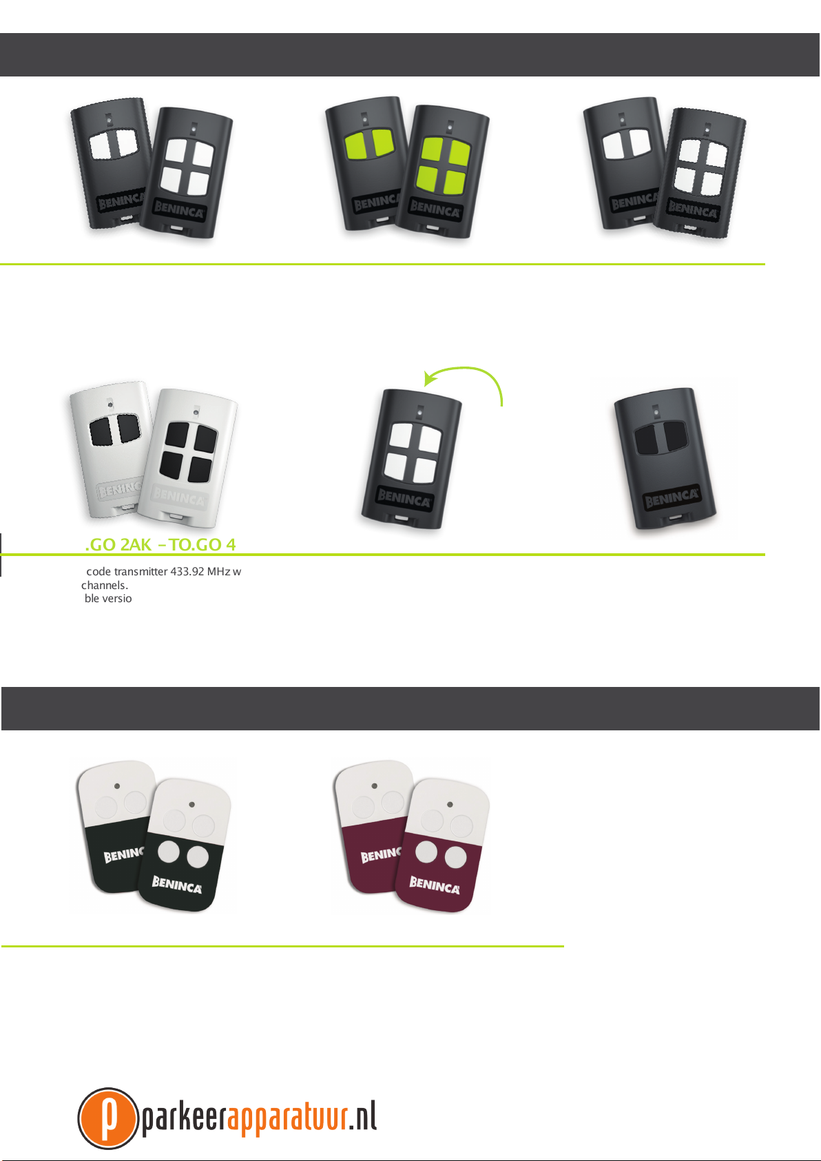
TO.GO 2VA -TO.GO 4VATO.GO 2A -TO.GO 4A
TO.GO 2AK -TO.GO 4AK
TO.GO 2AS -TO.GO 4AS
Rolling code transmitter 433.92 MHz with
2 or 4 channels with ARC encoding to
use only with the new compatible ARC
receivers.
Rolling code transmitter 433.92 MHz with
2 or 4 channels.
Cloneable version that allows for creating
a duplicate of a Fixed Code transmitter
already stored or can be used as a
normal ARC encoded transmitter.
Rolling code transmitter 433.92 MHz
with 2 or 4 channels with ARC or HCS
encoding (settable). The factory setting
is ARC code that can be used with both
types of Rolling-code receivers made by
Benincà.
Transmitter 433.92 MHz with 2 or 4
channels and ARC rolling code supplied in
packages with consecutive serial number.
The package bears the initial and nal
serial numbers to use with the Advantouch
programmer for storing a high number of
transmitters by a single operation.
>
TO.GO 4A
SP ECIAL
EDITION
with
soft-touch
treatment
TO.GO 4ASE
Rolling code transmitter 433.92 MHz with
4 channels with ARC code and special
soft-touch treatment that makes it soft
to the touch and scratch-resistant, thus
ensuring a longer service life. Only for use
with the new ARC compatible receivers.
TO.GO 2QV
Rolling code transmitter 868MHz with 2
channels with HCS encoding.
HAPPY-MODELS ANDSPECIFICATIONS
HAPPY 2VA -HAPPY 4VA HAPPY 2AK -HAPPY 4AK
Rolling code transmitter 433.92 MHz
with 2 or 4 channels with ARC or HCS
encoding (settable). The factory setting
is ARC code that can be used with both
types of Rolling-code receivers made by
Benincà.
Rolling code transmitter 433.92 MHz with
2 or 4 channels.
Cloneable version that allows for creating
a duplicate of a Fixed Code transmitter
already stored or can be used as a
normal ARC encoded transmitter.
>
Page 4

THERECEIVERS
>
The receivers compatible with the new TO.GO/HAPPY ARC transmitters are available in 4 versions:
External box receiver to apply to the inside of the controller container, if the controller is not
provided with built-in receiver.
This type of receiver has a terminal board for the connection of the power supply, the radio
antenna and two settable outputs. B eing a 100% independent device, it can be used for any
application requiring a radio control.
In this guide we will refer to the model ONE2WB (article code 9673103), a two-channel receiver
that handles ARC, HCS and programmable codes
Plug-in receiver for controllers equipped with a quick molex connector.
This type of receiver, once inserted into the controller connector, works line a built-in receiver,
receiving power and antenna signal from the controller, while the switch channels are handled
by the controller. P rogramming is carried out using the button and the LED indicator on the
receiver.
In this guide we will refer to the model ONE2WI (article code 9673102), a two-channel receiver
that handles ARC, HCS and programmable codes
Built-in receiver, integrated into the controller, programmable via dip-switches/trimmers.
This type of controller features a programming button and a LED indicator that allows the user
to set up the functions of the integrated receiver.
In this guide we will refer to the model CP J 3, the controller incorporated in the geared motors
J M.3, the procedure is also similarto that of other controllers equipped with integrated receiver.
EEPROM
>
Built-in receiver, integrated into the controller, programmable via LCD display.
This typeofcontrollers alwayshas aradio menuthroughwhichyoucan perform allthe operations
for programming the integrated receiver. The radio menu also allows for the management of
advanced features of each device.
In this guide we will refer to the model BRAINY, the procedure is, once again, similar to that of
other controllers with LCD display
It is important to know that most B enincà receivers store transmitter codes in a special
removable memory (EEPROM).
The picture to the side shows an EEPROM installed on a controller, in the instructions included
with the device always show the position of the EEPROM.
Should you need toreplace a controller or a receiver, you can remove the EEPROM fromthe old
card and install it on the new one (as long as the devices are of the same model).
This will prevent having to store again all the transmitters, a very useful feature especially if a
receiver is used by many users (condominiums, residences, communities).
There is also a special high-capacity EEPROM available (art. MEM 2048) able to store a large
number of transmitters (2048) compared to standard EEP ROM (that can store usually onyl 64
codes).
4
Page 5

TO.GO/HAPPY-STORINGOFTRANSMITTERS
>
BOX RECEIVER (ONE.2WB/ONE.2WO AND EARLIER VERSIONS)
>
Connect the antenna to the appropriate input using only RG58 cable, then power the device according to the instructions given in
the userʼs manual.
The box receivers usually feature two transmission channels (CH1 and CH2), to identify the channel on which you are performing
the programming, the LED color is used:
The channel CH 1 is associated with the color RED
The channel CH 2 is associated with the color GREEN
To store a transmitter in the memory proceed as follows:
• Press the Program button, using a paper clip until the red LED lights up.
• Within 5 seconds, press the button of the transmitter to be associated with the channel 1.
• Within the following 5 seconds, you can save a new transmitter to channel 1.
• To associate the channel 2, press 2 times the Program button of the device until the green LE D lights up.
• Within 5 seconds, press the button of the transmitter to be associated with the channel 2.
• Within the following 5 seconds, you can save a new transmitter to channel 2.
The box receivers also allow for setting of other functions such as setting a switching time or the output switching mode (mono-
stable/bistable). For more information refer to the instructions supplied with the device.
M
A
R
G
O
R
P
LED
I
I
I
I
I
I
T1
PLUG-IN RECEIVER (ONE. 2WI AND EARLIER VERSIONS)
>
Insert the plug-in receiver in the molex connector in the control unit.
The molex connector has a dedicated plug-in side that must be observed.
The control unit must be powered, the antenna must be connected to the relevant terminals using exclusively an RG58 cable.
The plug-in receivers usually feature two transmission channels (CH1 and CH2), to identify the channel on which you are performing the programming, the LED color is used:
The channel CH 1 is associated with the color RED
The channel CH 2 is associated with the color GREEN
To store a transmitter in the memory proceed as follows:
• Press the Program button, until the red LED lights up.
• Within 5 seconds, press the button of the transmitter to be associated with the channel 1.
• Within the following 5 seconds, you can save a new transmitter to channel 1.
• To associate the channel 2, press 2 times the Program button of the device until the green LE D lights up.
• Within 5 seconds, press the button of the transmitter to be associated with the channel 2.
• Within the following 5 seconds, you can save a new transmitter to channel 2.
The plug-in receivers also allow for setting of other functions such as setting a switching time or the output switching mode (mo-
nostable/bistable). For more information refer to the instructions supplied with the device.
PROGRAM
LED
I
I
I
I
I
I
T1
5
Page 6

CONTROL UNITS WITH BUILT-IN RADIO AND LEARNING BUTTON
T1
OK OKOK
+-+
--
OK
DL1
1234
P.P
PGM
CL
ON
>
This type of controller features a programming button and a LED indicator that allows the user to set up the functions of the integrated receiver.
The control unit must be powered, the antenna must be connected to the relevant inputs using exclusively an RG58 cable.
The name of the button and that of the LED vary depending on the controller. In the example below, we refer to a CP.J 3 controller:
• Press 1 time the PGM button for 1s, LED DL1 starts blinking with a pause of 1s to indicate, to show that the receiver is waiting
for a transmitter code.
• Press within 10s the button of the transmitter to be memorised with the P.P. function. After storing the transmitter, the receiver
automatically exits the programming phase.
• Within 10s from saving, you can save other transmitters.
• Some controllers use the LED or the assistive light to conrm that the transmitter has been saved successfully.
• To exit the programming mode without saving any transmitter, wait 10s.
Some control units may feature special functions (pedestrian opening, second radio channel). Consult the deviceʼs instructions for
more information.
T1
CONTROL UNITS WITH BUILT-IN RADIO CONTROL AND LCD DISPLAY
>
This type of controllers have a radio menu through which you can performallthe operations forprogrammingthe integrated receiver.
The control unit must be powered, the antenna must be connected to the relevant inputs using exclusively an RG58 cable.
Press the button <OK>, the LCD display switches on and opens the rst menu available (usually “P arameters” P AR).
• Use the button <+> or <->to navigate in the menu “RADI” (RADIO).
• Press the button <OK>, the display shows the rst function available in the menu (usually the function PP).
• Select with the button <+>or <-> the “P P ” function.
• Press the button <OK>, the display shows the message “PUS H” to indicate that a button is waiting and prompts you to push
the button of the transmitter that you want to associate.
• Upon completion, “OK” will appear on the display.
The radio menu also has other functions specic to the type of controller (pedestrian opening, second radio channel, separate
open/close); refer to the instructions included with the device
6
Page 7

T1 T1T1 T2
TX 1 TX 1 TX 2
TO.GO-ADVANCEDFUNCTIONS
>
SELECTION OF THE TYPE OF ENCODING (TO. GO/HAPPY VA)
>
VA series transmitters can operate in either HCS or ARC mode.
This allows you to use the transmitters on systems equipped with HCS receivers.
The transmitter comes with ARC mode factory setting.
To change the encoding type press simultaneously for 20 seconds the keys T1 and T2.
After a few seconds the LED will blink, indicating the mode that you are about to enable:
2 ashes and pause of 1 second, the transmitter is to be set up as HCS
3 ashes and pause of 1 second, the transmitter is to be set up as ARC
when the LED turns on steadily lit, it means that the transmitter has changed the mode.
HIDDEN BUTTON ACTIVATION
>
Some advanced features require pressing the “Hidden Key”.
In traditional transmitters, the hidden key is a button inside the container that must be pressed
with a paper clip or a piece of wire.
In new transmitters TO.GO/HAPP Y ARC, the “Hidden Key” can be accessed by pressing the
keys T1 and T2 simultaneously for at least 3 seconds.
When the LED ashes, it means that the “Hidden Key” code was sent.
Attention: If the LE D ashes before 3 seconds, it means that the keys were not pressed simultaneously and you did not send the “Hidden Key” code
20 sec
L
E
D
T
1
T
2
T
4
L
E
D
T
1
T
2
T
4
3 sec
REMOTE LEARNING
>
Remote learning allows you to enter a new transmitter in the receiver if you have a previously memorized transmitter, without having
to access the receiver.
Therefore, you will quickly have a new transmitter that resembles the one originally stored.
It is mandatory to operate within the reception range of the receiver.
The procedure is different depending on the device used. There are still two possible modes:
Remote Learning In Receivers One WB/WI
Proceed as follows:
• Press the hidden key of the transmitter saved, namely the simultaneous combination of T1 and T2 keys, for 3 seconds (the
red LED on the transmitter ashes)
• Press within 5 seconds the key on the previously memorized transmitter corresponding to the channel to associate with the
new transmitter.
• Within 5 seconds, press the key of the new transmitter to be associated with the selected channel.
• The receiver exits the programming mode, check the proper operation of the new transmitter saved.
The procedure can be summarized as follows:
-Hidden key of the currently active transmitter (T1 + T2 for 3s)
-Key of the transmitter already operative with the function to duplicate (within 5s)
-Key of the new transmitter (5s)
Notes:
Remote learning is only possible with ARC and HCS transmitter, and is not possible with programmable code transmitters.
7
Page 8

Remote Learning In Receivers Built Into The Control Units
Proceed as follows:
• Press the hidden key of the transmitter saved (the red LED on the transmitter ashes)
• Press within 5 seconds the key on the previously memorized transmitter corresponding to the channel to associate with the
new transmitter.
• Press the hidden key of the transmitter saved (the red LED on the transmitter ashes)
• Within 5 seconds, press the key of the new transmitter to be associated with the selected channel.
• The receiver exits the programming mode, check the proper operation of the new transmitter saved.
T1T1 T2 T1T1 T2
TX 1 TX 1 TX 2 TX 2
The procedure can be summarized as follows:
-Hidden key of the currently active transmitter (T1 + T2 for 3s)
-Key of the transmitter already operative with the function to duplicate (within 5s)
-Hidden key of the new transmitter (T1 + T2 for 3s)
-Key of the new transmitter (5s)
Notes:
Some controllers signal the various learning phases via the assistive or the ashing light.
Remote learning is only possible with ARC and HCS transmitter, and is not possible with programmable code transmitters.
For security reasons, remote learning is prevented during motor opening/closing.
In some cases, the procedure must be performed with the doors fully opened; consult the deviceʼs instructions..
TO. GO/HAPPY AK CLONEABLE
>
AK series transmitters can be programmed with the same code as a programmable transmitter or K or P series, already stored in
a system, or to replace most xed-code transmitters on the market with a simple and fast procedure without the need to access
the receiver nor to open the remote control.
An important innovation featured by these new AK versions is the implementation of double-encoding, ARC or xed: this transmitter can be used as a normal cloneable transmitter or as a real ARC transmitter with variable code. In fact, the AK radio control,
if not used to clone a xed code transmitter, sends the code by default with Advanced Rolling Code encoding. The only way to
make it use the xed-code is to program it starting from TO.GOWP or TO.GOWK.
Quick cloning
In quick cloning you get a transmitter that replicates exactly every single channel of the original transmitter in the new TO. GO/
HAPP Y AK; we recommend using a 2AK to clone a two-channel original transmitter and a 4AK to clone a four-channel transmitter.
Proceed as follows:
1) press and hold the key T1 of the new transmitter AK. When pressing T1, the LED lights up steadily, after 5 seconds it will begin
to ash rapidly, after 15s to ash slowly.
2) after about 15s, put the original transmitter near the new transmitter as shown in the picture, and continue
to hold the key T1 on the new remote control, and press any button on the original remote control.
3) if the procedure was completed successfully, the LE D of the new transmitter AK will turn o. Release all the
keys pressed.
All channels of the original TO.GO(HAPPY are replicated on the AK.
N.B.: Use for both remote controls batteries charged.
If after 15 sec. the red LED on the new transmitter is not o, release the buttons of the remote control and
after 1 minute, repeat from step 1, being careful to place the original transmitter as shown in the picture.
Advanced cloning
In advanced cloning you can choose which channel of the original transmitter will be replicated on the AK.
For example, you can replicate channel 3 of an old transmitter on channel 1 of a AK, which is not possible
during quick cloning.
Proceed as follows:
1) on the new AK, press and hold the key of which you want to replicate the function of the original. When you
press the button, the LED lights up steadily, after 5 seconds it will begin to ash rapidly.
2) after 5s, put the original transmitter near the new transmitter as shown in the picture, and continue to hold
the key on the new remote control, and press the button of the original remote control whose code you intend
to copy.
3) if the procedure was completed successfully, the LE D of the new transmitter AK will turn o. Release all the keys pressed.
The channel chosen in the original TO.GO/HAPP Y is now replicated in the new AK.
N.B.: Use for both remote controls batteries charged.
If after 30 sec. the red LED on the new transmitter is o, release the buttons of the remote control and repeat from step 1, being
careful to place the original transmitter as shown in the picture.
8
Page 9

BATTERY REPLACEMENT
>
If during normal operation, the LED ashes by pressing any button, the battery is low and needs to be replaced.
To replace the battery, open the battery lid using a screwdriver as shown in the picture, by lightly pressing on both slits.
Replace the battery following the polarity, the symbol +is indicated in the printed circuit board.
TO.GO
1
2
V
+
ALCALINE A23
HAPPY
2
1
+
ALCALINE A23
WARNING!:
Batteries are special waste and must be disposed of in compliance with the regulations in force.
V
9
Page 10

AUTOMATISMI BENINCÀ SpA - Via Capitello, 45 -36066 S andrigo (VI) ITALY - Tel. 0444 751030 r.a. -Fax 0444759728
www.beninca.com -sales@beninca.it
 Loading...