

Page 1

DU.350CF
SB.DU350L / SB.DU350K
L8542575
Posa della cassa di fondazione
Effettuare lo scavo secondo indicazioni di fig. 1 prevedendo un
drenaggio per l’acqua e un arrivo cavi su uno dei 4 angoli dove
esistono apposite forature. Cementare la cassa avendo cura di
controllarne l’orizzontalità tramite livella. In caso non sia possibile
realizzare l'installazione standard, è possibile installare il motore
all'interno (fig 2).
Foundation box laying
Dig as per instructions given in fig. 1 and make sure that on
one of the four angles, where suitable holes have been made,
a water drainage and a cable terminal have been prearranged.
Cement the box and check it is horizontal with the level. If the
standard installation is not possible, the motor can be fitted
inside (Fig.2).
Versenkung des Gründungskastens
Ausgrabung gemäß Bild 1 vornehmen und einen Wasserabzug
und einen Kabeleinlaß an einer der vier Ecken vorsehen, an denen
Bohrungen dazu bestehen. Den Kasten zementieren, wobei Sie
mit einer Wassewaage feststellen, ob er waagerecht liegt. Sollte
die Standardkonfiguration für die Installation nicht geeignet sein,
kann der Motor auch im Inneren installiert werden (Abb.2).
Mise en place de la caisse de fondation
Faire une tranchée de fondation en suivant les indications de
la figure 1 en prévoyant un drainage pour l’eau et une arrivée
des fils électriques sur un des quatre angles où sont prévus les
trous correspondants. Cîmenter la caisse aprés avoir contrôlé
l’horizontalité avec un niveau à bulles. Si l’installation standard n’est
pas réalisable, le moteur peut être installé à l’intérieur (fig. 2).
Instalación de la caja de cementación
Efectuar la excavación según las indicaciones de la fig. 1
previendo un drenaje para el agua y una entrada de cables por
uno de los 4 ángulos en donde existen los correspondientes
agujeros. Cimentar la caja teniendo cuidado de controlar la
horizontalidad mediante nivel. Si no es realizable la instalación
estándar, se puede instalar el motor al interior (fig 2).
Wbudowanie skrzynki podziemnej
Wykonać wykop według wskazówek podanych na Rys. 1,
pamiętając o drenażu napływającej wody oraz miejscu przewłoki
na przewody w jednym z czterech rogów, w których odwiercone
zostały przeznaczone do tego otwory. Sprawdzić prawidłowe
wypoziomowanie skrzynki przy pomocy poziomicy, a następnie
zacementować ją. Jeżeli standardowa instalacja nie jest możliwa,
silnik może być zainstalowany wewnątrz (rys 2).
Installazione dello sblocco
Saldare accuratamente il gruppo di traino P all'anta curando
l'allineamento tra la cerniera superiore ed il perno, come mostrato
in figura 3.
•
SB.DU350L: fissare lo sblocco all'anta utilizzando le quattro
viti M6x35 fornite in dotazione (fig 4)
•
SB.DU350K: fissare lo sblocco all'anta utilizzando due viti
M6x35 e due M6x30 come in figura 5.
Inserire la sfera S tra la cassa di fondazione e il gruppo di traino,
come illustrato in figura 6. Per fissare il coperchio di protezione,
inserire i dadi A nei supporti B e , successivamente, i supporti
B nelle alette di fissaggio C (fig. 7); posizionare il coperchio e
fissarlo ai supporti utilizzando le viti fornite in dotazione.
How to install the release device
Carefully weld the drive group P to the leaf, taking care that the
upper hinge and the pivot be aligned, as shown in Figure 3.
•
SB.DU350L:fit release to the leaf by means of the four screws
M6x35 supplied (Fig.4)
•
SB.DU350K:
fit the release to the leaf by means of the two
screws M6x35 and two screws M6x30, as shown in Figure 5.
Introduce the sphere S between the foundation case and the
drive group, as shown in Figure 6. In order to fit the protection
cover, insert the nuts A in the special supports B and then the
supports B in the fitting tongues C (Fig. 7). Place the cover and
fix it to the supports by means of the screws supplied.
Entsicherungsvorrichtung installieren
Die Zugvorrichtung P an den Flügel schweißen und dabei darauf
achten, dass das obere Scharnier mit dem Stift ausgerichtet ist
(siehe Abbildung 3).
•
SB.DU350L: Die Entsicherungsvorrichtung mit Hilfe der vier
Schrauben M6x35 (mitgeliefert) an den Flügel befestigen (Abb. 4).
• SB.DU350K: Die Entsicherungsvorrichtung mit Hilfe der zwei
Schrauben M6x35 und der zwei Schrauben M6x30 wie in Abb.
5 gezeigt, befestigen.
Die Kugel S zwischen Fundamentkasten und Zugvorrichtung
einsetzen (Abb. 6).Um die Schutzabdeckung anzubringen, die
Muttern A auf die Halterungen B und danach die Halterungen
B auf die Befestigungsflügel C (Abb. 7) setzen. Die Abdeckung
positionieren und an den Halterungen mit den mitgelieferten
Schrauben befestigen.
Installation du déblocage
Souder soigneusement le groupe de d’entrainement P sur le vantail
en prêtant beaucoup d’attention à l’alignement entre la charnière
supérieure et le tourillon, comme illustré dans la figure 3.
• SB.DU350L: fixer le déblocage sur le vantail en utilisant les
quatre vis M6x35 fournies (fig. 4)
•
SB.DU350K:
fixer le déblocage sur le vantail en utilisant deux
vis M6x35 et deux vis M6x30 comme illustré dans la figure 5.
Insérer la sphère S entre le la caisse de fondation et le groupe
d’entraînement, comme illustré dans la figure 6. Pour fixer le
couvercle de protection, insérer les écrous A dans les supports
B et, par la suite, les supports B dans les aubes de fixation C
(fig. 7); placer le couvercle et le fixer aux supports en utilisant
les vis fournies.
Instalación del desbloqueo
Soldar cuidadosamente a la hoja el grupo de arrastre P,
prestando atención a la alineación entre la bisagra superior y el
perno, como mostrado en la figura 3.
•
SB.DU350L: fijar a la hoja el desbloqueo, utilizando los cuatrro
tornillos M6x35 suministrados (fig. 4)
•
SB.DU350K: fijar a la hoja el desbloqueo, utilizando dos
tornillos M6x35 y dos M6x30 como mostrado en la figura 5.
Insertar la bola S entre la caja de fundación y el grupo de arrastre,
como mostrado en la figura 6. Para fijar la tapa protectora,
insertar las tuercas A en los soportes B y , seguidamente, los
soportes B en las aletas de fijación C (fig. 7); poner la tapa y
fijarla a los soportes utilizando los tornillos suministrados.
Montaż modułu odblokowania
Dokładnie przyspawać mo duł poci ągowy P do skrzydła
zwracając uwagę, aby górny zawias i kołek były wyosiowane,
jak przedstawionio na rysunku 3.
•
SB.DU350L: umocować moduł odblokowania do skrzydła
po sługując się w tym celu czte rema śrub ami M6x35
znajdującymi się na wyposażeniu (rys 4)
•
SB.DU350K: umocować moduł odblokowania do skrzydła
posługując się dwoma śrubami M6x35 i dwoma śrubami
M6x30 jak na rysunku 5.
Umieścić kulkę S między płytą fundamentową a modułem
pociągowym, jak przedstawiono na rysunku 6. Aby umocować
pokrywę ochronną, należy umieścić nakrętki A na wspornikach B
a, następnie, umieścić wsporniki B na skrzydełkach mocujących
C (rys. 7); umieścić pokrywę i umocować ją do wsporników za
pomocą dostarczonych śrub.
05/2011 R1
Page 2
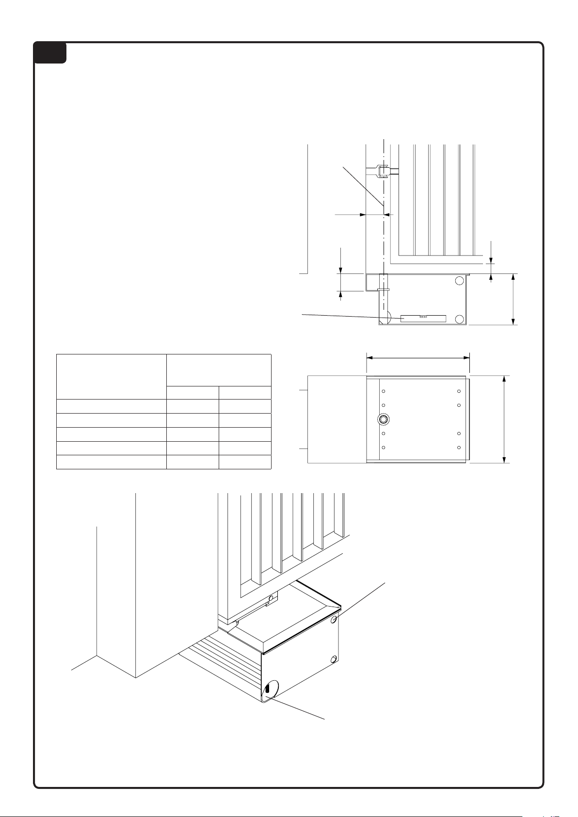
Foro per drenaggio acqua.
Water drainage hole.
Bohrung für Wasserabzug.
Trou pour drainage des eaux.
Agujero para drenaje de agua.
Otwór drenowania wody.
Foro per entrata cavi.
Cable hole.
Bohrung für Kabeleinlaß.
Trou d’entrée pour fils électriques.
Agujero para entrada de cables.
Otwór przechodzenia przewodów.
Controllare che l’asse A sia perfettamente a piombo.
Check axis A is plumbed.
Prüfen, ob Achse A vollkommen lotrecht.
Contrôler que l’axe A soit parfaitement d’aplomb.
Controlar que el eje A esté perfectamente aplomado.
Sprawdzić czy oś A jest dokładnie w pionie.
Ingombri cassa art. DU.350CF.
Overall dimensions box art. DU.350CF.
Raumbedarf Kasten DU.350CF.
Dimensions caisse art. DU.350CF.
Volumen caja art. DU.350CF.
Gabaryt skrzynki art. DU.350CF.
70 min.
211
400
400
A
Controllare l’orizzontalità.
Check it is horizontal.
Prüfen, ob Lage waagerecht.
Contrôler l’horizontalité.
Controlar la horizontalidad.
Sprawdzić wypoziomowanie.
1
Lunghezza anta / Door leaf width
Flügellänge
/
Longueur porte
Longitud hoja / Dł. skrzydła
Peso anta / Door leaf weight
Türflügelgewicht
/
Poids porte
Peso hoja / Ciężar skrzydła
DU.350N DU.350NV
2,0 m 800 kg 700 kg
2,5 m 700 kg 600 kg
3,0 m 600 kg 500 kg
3,5 m 550 kg --
4,0 m 500 kg --
66
64
Page 3

2
Posizione motoriduttore.
Reduction gear position.
Stellung Getriebemotor.
Position motoréducteur.
Posición del motorreductor.
Pozycja siłownika
Posizione motoriduttore.
Reduction gear position.
Stellung Getriebemotor.
Position motoréducteur.
Posición del motorreductor.
Pozycja siłownika
Standard / Standard / Standard / Standard / Standard / Standard
Apre.
Open.
Öffnen.
Ouvre.
Abre.
Otwarcie
Anta.
Gate wing.
Torflügel.
Porte.
Hoja.
Skrzydło bramy.
Anta.
Gate wing.
Torflügel.
Porte.
Hoja.
Skrzydło bramy.
Muro.
Wall.
Wand.
Mur.
Muro.
Mur
Muro.
Wall.
Wand.
Mur.
Muro.
Mur
Interno / Inside / Innenraum / Intérieur / Interior/
Wnętrze obudowy
Anta.
Gate wing.
Torflügel.
Porte.
Hoja.
Skrzydło bramy.
Anta.
Gate wing.
Torflügel.
Porte.
Hoja.
Skrzydło bramy.
90° 90°
Muro.
Wall.
Wand.
Mur.
Muro.
Mur
Muro.
Wall.
Wand.
Mur.
Muro.
Mur
Apre.
Open.
Öffnen.
Ouvre.
Abre.
Otwarcie
110°110°
3
Curare l’allineamento tra la cerniera superiore ed il perno.
Align the top hinge with the pivot.
Oberes Scharnier und Zapfen sind aufeinander auszurichten.
Soigner l’alignement entre la charnière supérieure et le pivot.
Cuidar la alineación entre la bisagra superior y el perno.
Dbać o równopadłość linii pomiędzy górnym wpustem a sworzniem.
P
Saldare accuratamente.
Weld accurately.
Sorfältig schweißen.
Souder parfaitement.
Soldar cuidadosamente.
Przyspawać dokładnie.
Page 4

76
B
C
C
A
A
S
4 5
Vite TCEI M6x35 (in dotazione).
Screw TCEI M6x35 (supplied).
Schraube TCEI M6x35 (beiliegend).
Vis TCEI M6x35 (fournies).
Tornillo TCEI M6x35 (suministrados).
Śruba TCEI M6x35 (w wyposażeniu).
Vite TCEI M6x35 (in dotazione).
Screw TCEI M6x35 (supplied).
Schraube TCEI M6x35 (beiliegend).
Vis TCEI M6x35 (fournies).
Tornillo TCEI M6x35 (suministrados).
Śruba TCEI M6x35 (w wyposażeniu).
Vite TCEI M6x30 (in dotazione).
Screw TCEI M6x30 (supplied).
Schraube TCEI M6x30 (beiliegend).
Vis TCEI M6x30 (fournies).
Tornillo TCEI M6x30 (suministrados).
Śruba TCEI M6x30 (w wyposażeniu).
 Loading...