

Page 1
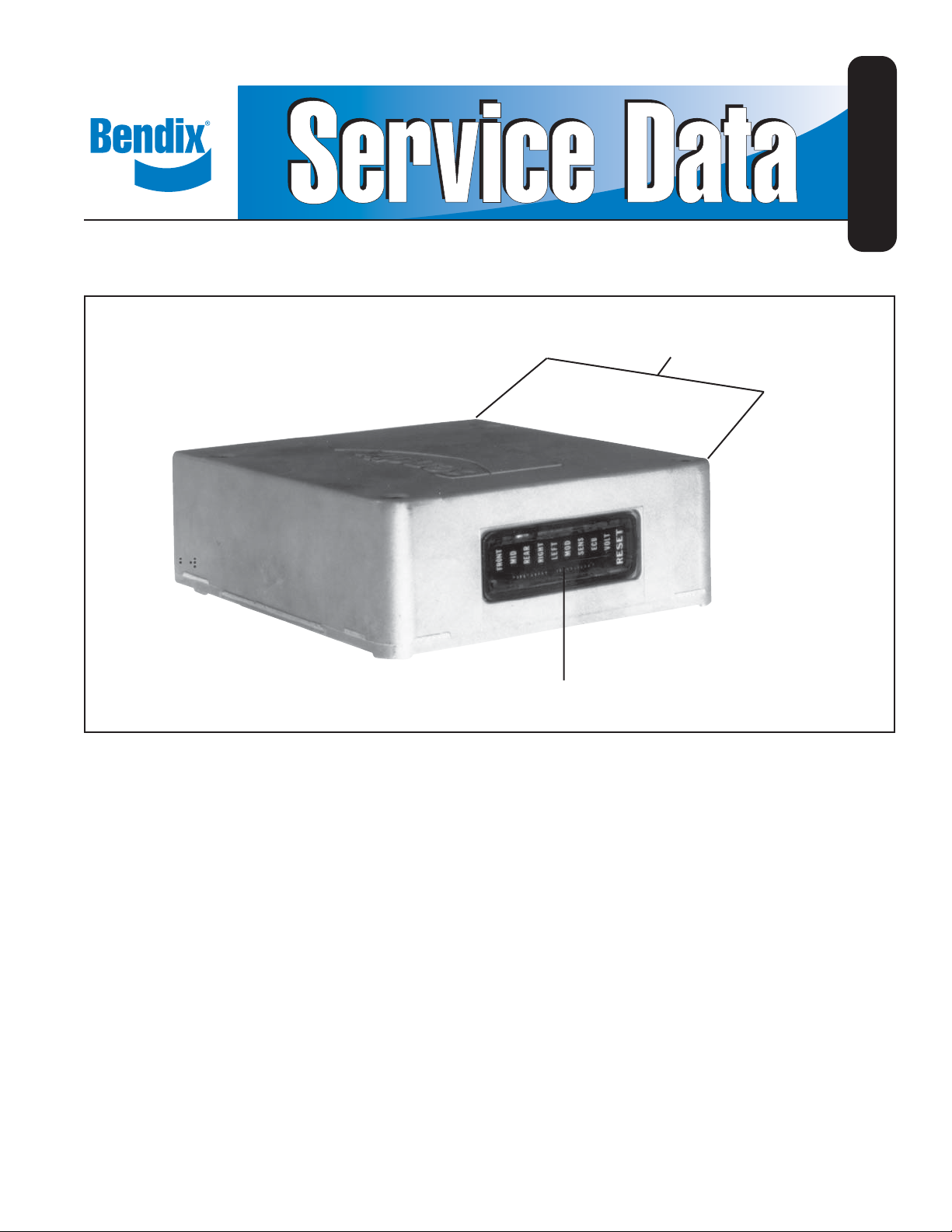
Bendix® EC-15™ AntiLock Controller Assembly
SD-13-4785
MOUNTING
HOLES (4)
FIGURE 1 - EC-15™ ELECTRONIC CONTROLLER
DESCRIPTION
GENERAL
Bendix antilock systems utilizing the EC-15™ electronic
controller assembly provide full vehicle, wheel control
braking for buses, trucks, and truck tractors. By minimizing
the potential of “brake lock-up” on all wheels during
aggressive braking the vehicle retains a high degree of
stability and steerability , and in most cases vehicle stopping
distance is reduced.
In order to provide full vehicle, wheel control braking, the
EC-15™ controller assembly is used in combination with
the following components:
- Four, individual wheel speed sensors
- Four, air pressure modulator valves
- Antilock condition lamp (dash mounted)
DIAGNOSTICS
WINDOW DISPLAY
PHYSICAL
The EC-15™ controller electronics, that regulate the function
of the antilock system, are contained in a die cast aluminum
housing and are environmentally protected. The metal
housing, coupled with the design of the digital electronics,
is intended to provide a high degree of protection from
radio and electromagnetic interference.
A diagnostics display window with 9 light emitting diodes
(LEDs) and a magnetically actuated reset switch is
incorporated in the housing for troubleshooting and
diagnostic purposes.
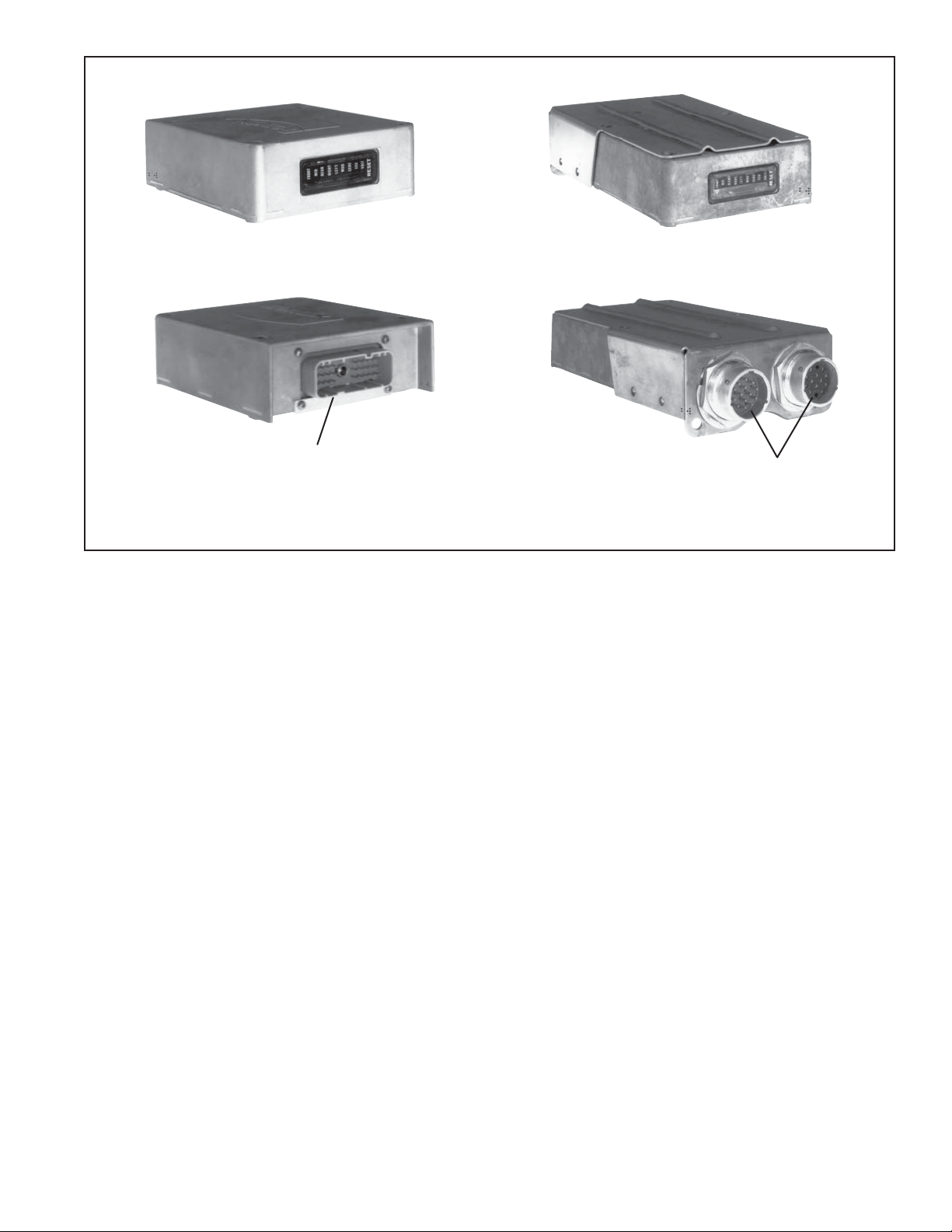
Two types of electrical connectors are currently used to
connect the EC-15™ controller assembly to the antilock
system components; a single, 30 pin, Packard Electric,
150 series “Metri-pack” or a pair of 14 pin, Deutsch, HID
30 series connectors.
1
Page 2
SERVICE
ACTUATOR
REAR AXLE
™
CR-15
ASSEMBLY
™
EC-15
CONTROLLER
TANDEM AXLE
ANTILOCK
RELAY
™
AR-1
SERIAL LINK
RELAY
DASH LAMP
CONTROL
RETARDER
™
M-21
SERVICE
BRAKE VALVE
QUICK
SENSOR
WHEEL SPEED
EXCITER (4)
RELEASE VALVE
(4)
SERVICE
FRONT AXLE
CHAMBER
MODULATOR
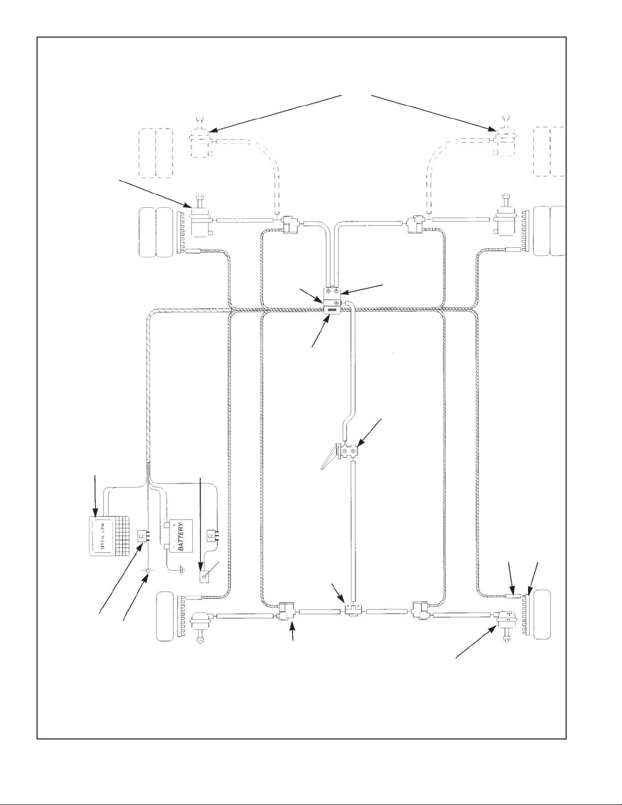
FIGURE 2 - EC-15™/CR-15™ ANTILOCK SYSTEM
2
Page 3
PACKARD 30 PIN
CONNECTOR
FIGURE 3 - EC-15™ CONTROLLER AND CONNECTOR STYLES
DEUTSCH 14 PIN
CONNECTORS
MOUNTING
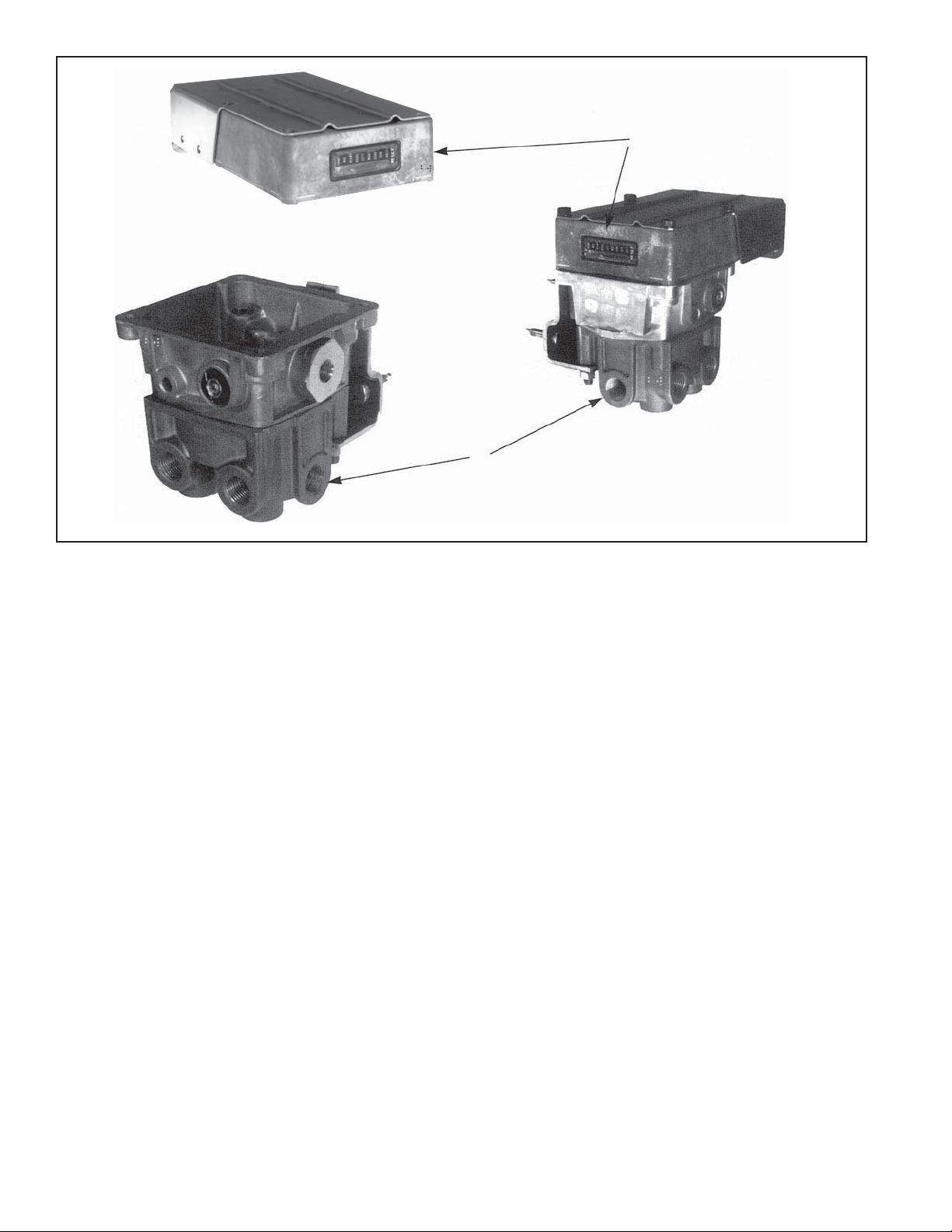
The EC-15™ controller is available in two different mounting
styles. One model is designed to be mounted on an antilock
relay valve such as the AR-1™ valve (see Service Data
Sheet SD-13-4795). The AR-1™ valve is a modifi ed version
of the R-12® relay valve. When the EC-15™ controller is
mounted on an antilock relay valve the resulting assembly
receives a different designation. For example when the
EC-15™ antilock controller is mounted on the AR-1™ valve
the resulting assembly is known as a CR-15™ antilock
controller relay. The other EC-15
™
controller model is
intended for bracket mounting to a frame member and is
not attached to an antilock relay valve.
CONTROLLER INPUTS/OUTPUTS
The EC-15™ controller receives information from several
components in the antilock system and, based on these
inputs, issues commands or delivers information. Some
portions of the EC-15™ controller both receive and deliver
commands and information.
INPUTS
Wheel speed information is provided to the EC-15™
controller via a wiring harness from individual wheel speed
sensors located at or in the vehicle wheels. Working in
conjunction with an exciter or tone ring, wheel speed
sensors provide information to the EC-15™ controller in the
form of an AC signal which varies in voltage and frequency
as the speed of the wheel increases or decreases. The
™
EC-15
controller is designed to receive wheel speed
information, from various wheel speed sensor models, at
the rate of 100 pulses per wheel revolution. The EC-15™
controller is able to simultaneously receive, and individually
interpret, speed signals from four wheel speed sensors.
Vehicle power is supplied to the EC-15™ controller from
the ignition switch through a fuse or circuit breaker. The
electrical ground for the EC-15™ controller is the vehicle
chassis.
OUTPUTS
®
Modulators, like the Bendix
M-21™, are the means by
which the EC-15™ antilock controller is able to modify driver
applied air pressure to the service brakes. The modulator
is an electrically controlled air valve that is located near
3
Page 4
AR-1
FIGURE 4 - EC-15™ CONTROLLER MOUNTED ON AN AR-1™ VALVE
™
ANTILOCK
RELAY VALVE
EC-15™
ELECTRONIC
CONTROLLER
the service actuator(s) it controls and is the last air valve
through which air passes on its way to the brake actuator.
A wiring harness connects the modulator to the EC-15™
antilock controller. Solenoid valves contained in the
modulator provide the electrical interface between the
EC-15™ controller electronics and the air brake system. The
EC-15™ controller is able to simultaneous and independently
control four individual modulator assemblies.
A dash light and its electrical relay is connected to, and
controlled by , the EC-15™ controller and serves as a means
of advising the driver of the condition of the antilock system.
A connection to the engine or transmission retarder is
provided on the EC-15™ controller which allows the EC-15™
controller to temporarily “disable” the retarder during certain
modes of operation. While the EC-15™ controller is capable
of this function, and connections are provided, it is not
always used. Use of the retarder disable function is not
essential but highly recommended for vehicles equipped
with a retarder.
The data link function enables the EC-15™ controller to
“report” its operating condition to a specialized, external
computer in response to certain commands it receives.
The EC-15™ controller data link confi guration conforms to
S.A.E. standard J1708 and the protocol, or coded language
used, conforms to S.A.E. standard J1587. There are two
connections to the EC-15™ controller devoted to the data
link. While the EC-15™ controller is capable of this function,
and connections are provided, it is not always used. Use
of the data link is not essential for the EC-15™ controller
to be functional.
4
OPERATION
GENERAL
The Bendix® EC-15™ antilock controller system provides
individual wheel control by using a wheel speed sensor
and modulator at each wheel. By monitoring the rate of
deceleration during braking, and subsequently adjusting
the brake application pressure at each wheel, the EC-15™
controller is able to provide improved braking between the
vehicle tire and the road surface it is on, while maintaining
vehicle stability.
The rear axle brakes are controlled completely independent
of each other and therefore brake application pressure
at an individual wheel is adjusted solely on the basis of
its behavior on the road surface on which it is traveling.
While each steering axle brake is under the control of an
individual modulator, the EC-15™ controller does not treat
these brakes totally independent of each other. The EC-15™
controller utilizes a modifi ed individual control philosophy
for the steering axle brakes. This is done in order to
minimize “steering wheel pull” in the event each wheel is
traveling on a different road surface (e.g.; ice close to the
curb and a dry crown). Essentially the EC-15™ controller
controls the braking force differences between the two
brakes. The wheel on dry pavement is initially given less
braking force and is brought up to optimum during the
stop, while the wheel on ice attempts to maintain optimum
braking during the entire stop.
Page 5
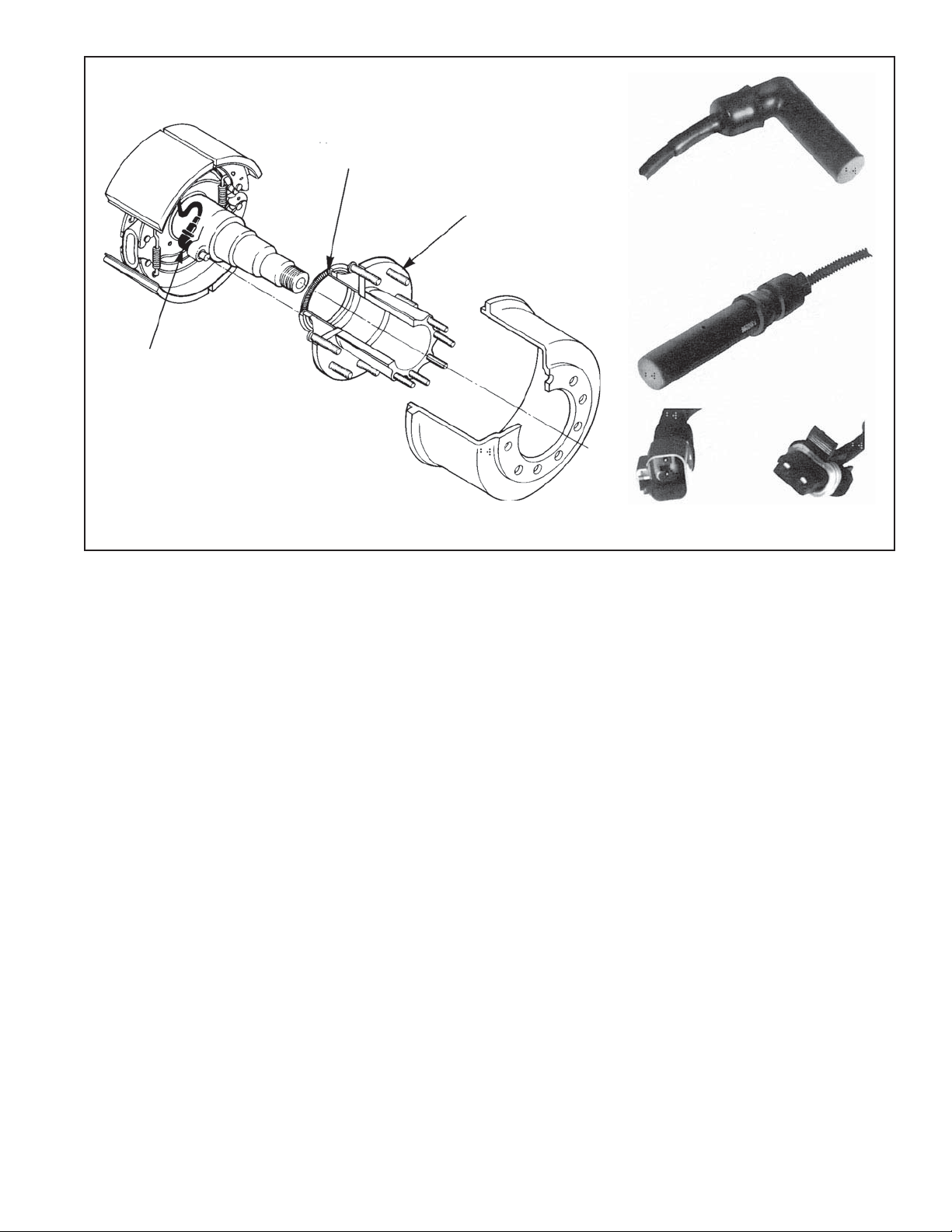
WS-20
SENSOR
™
SPEED
EXCITER RING
(100) TOOTH
HUB ASSEMBLY
WS-20™ ANGLED
SENSOR
WS-20
™
STRAIGHT
SENSOR
FIGURE 5 - WS-20™ WHEEL SPEED SENSORS
In the case of vehicles equipped with tandem rear axles
(6x2, 6x4), the wheel speed sensors are installed at the
wheels on the axle that is most likely to lose traction fi rst.
A single modulator controls both curb side brakes on the
tandem, and another modulator controls both brakes on the
driver’s side of the tandem. With this arrangement of the
speed sensors and modulators, both brakes on one side of
the tandem are treated as one since they will most likely be
on the same type of road surface. (Refer to fi gure 2)
NON-ANTILOCK BRAKE APPLICATION
During normal braking, air pressure from the brake valve
enters the control port of the service relay valve (either an
antilock or standard relay). The service relay delivers air
to, and through, the antilock modulator located near the
braked wheel, and into the brake actuator. The service
brakes are thus applied. If the wheel sensors do not detect
an impending wheel lock up, the EC-15™ controller does
not initiate any corrective action and the vehicle comes to
a stop in a normal fashion.
DEUTSCH
CONNECTOR
PACKARD
CONNECTOR
ANTILOCK CONTROLLED BRAKE
APPLICATION SYSTEM FULLY OPERATIONAL
If a service brake application is made and the wheel speed
sensors detect an impending wheel lockup, the EC-15™
controller will immediately begin modifi cation of the brake
application using the antilock modulator(s) at the affected
wheel(s).
Solenoid valves contained in the modulator are energized
and de-energized by the EC-15™ controller in order to modify
the brake application. When a solenoid coil is energized
its shuttle moves, and depending upon the function of the
specifi c solenoid, it either opens or closes, thereby causing
the exhaust or reapplication of air pressure to the brake
actuator. The solenoids in each modulator are controlled
independently by the EC-15™ controller. By opening and
closing the solenoid valves in the appropriate modulator,
the EC-15™ controller is actually simulating what the driver
does when he “pumps the brakes”. It must be remembered
however that unlike the driver, the EC-15™ controller is able
to “pump” each brake on the vehicle independently and
with far greater speed and accuracy.
5
Page 6
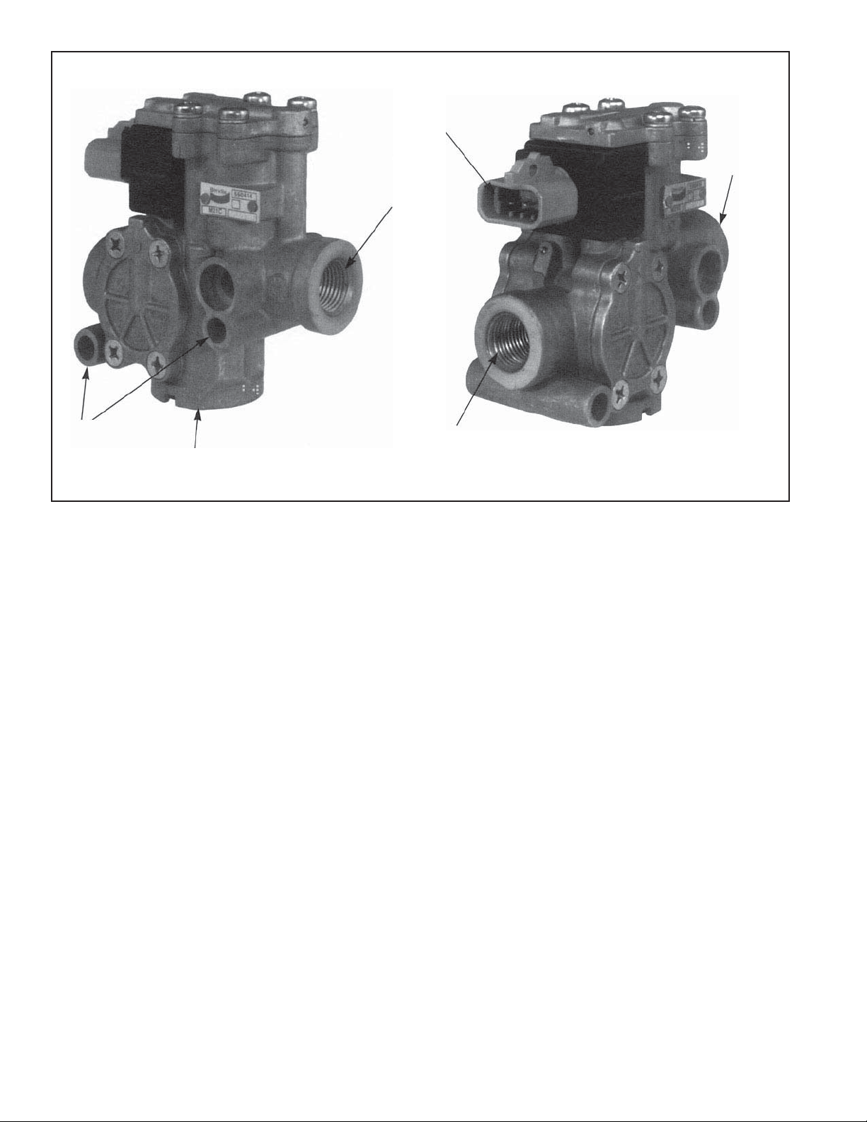
SUPPLY
SOLENOID
CONNECTOR
SUPPLY
MOUNTING
HOLES
EXHAUST
FIGURE 5 - M-21™ MODULATOR
ANTILOCK SYSTEM OPERATION COMPONENT FAILURE
The Bendix® EC-15™ controller handles equipment failure
using a conservative fail-safe philosophy. Any single
electrical failure of a component devoted to antilock
braking, results in simultaneous illumination of the antilock
condition lamp on the dash, a disabling of all or part of
the antilock system, and reversion to standard braking on
wheels no longer under the control of antilock. When coping
with wheel equipment (modulator or wheel speed sensor/
exciter) failure, the EC-15™ controller divides and separates
the brakes diagonally. For example; if the modulator at
the right front wheel has a broken wire lead, the EC-15™
controller disables the antilock function for BOTH the right
front and left rear wheels. The antilock will continue to
function on the left front and right rear wheels and will
remain under the control of the EC-15™ controller. (Note:
Right and left, front and rear are determined from the
driver’s seat. Left front is therefore the corner closest to the
driver). Depending upon the type of failure and its position
of occurrence the EC-15™ controller either disables all, or
only a portion, of the antilock system. A power or controller
failure, for instance, will result in complete disabling of the
antilock system and reversion to standard braking on all
wheels. Two or more failures, regardless of their position
of occurrence, will also result in the disabling of the entire
system. With the failed component approach described,
the vehicle will retain improved braking stability after a
DELIVERY
single failure. It should be remembered that the driver will
be advised of the degraded antilock operation via the dash
lamp and that standard air braking will still be available on
those brakes where the antilock has been disabled by the
EC-15™ controller.
ANTILOCK WIRING
The wires that carry information and power into and out of
the EC-15™ controller are generally grouped and terminate
at a connector. The wire groups or wire harnesses along
with the connectors are most often specified and or
supplied by the vehicle manufacturer. Two examples of the
connectors used on the EC-15™ controller are illustrated
in fi gures 7 & 8. The wiring harnesses and connectors are
weather proof and the wires that enter the connector are
sealed to the connector. The wire gauge used in the wire
harnesses is specifi c to the task performed.
When diagnosing wiring in the antilock system the
following general rules apply and should be followed where
applicable:
1. It is generally advisable to replace a wire harness rather
than repair individual wires in the harness. If a splice
repair must be made, it is important that the splice be
properly soldered with a rosin fl ux (not acid based fl ux)
and made water proof.
6
Page 7

2. Do not pierce wire insulation when testing. Check
for power, ground or continuity by disconnecting the
connector and testing the individual pins or sockets in
the connector.
3. Always check the vehicle hand book for wire and
connector identifi cation. Individual wire identifi cation
will differ depending upon the type of connectors in use,
the vehicle manufacturer, and the system features in
use.
4. While the retarder disable and serial link connections
(3 total) are present on all EC-15
not always used.
™
controllers they are
PREVENTATIVE MAINTENANCE
Every 3 months; 25,000 miles; or 900 operating hours,
1. Check all wiring and connectors to ensure they are
secure and free from visible damage.
2. Although the EC-15™ controller incorporates a self
check diagnostics, the LED display should be inspected
to ensure that they are functional. With the vehicle
ignition on, a magnet (800 gauss; capable of picking up
3 ounces) held to the LED reset switch should cause
all of the LED’s to illuminate. If one or more of the
LED’s DO NOT ILLUMINA TE and the antilock condition
lamp on the dash indicates the system is functioning
properly, the non-illuminated LED(s) should be noted
for future reference. Although the diagnostic capabilities
will be limited, the system will continue to function as
designed.
3. Road test the vehicle by making antilock stop from a
vehicle speed of 20 miles per hour. When an antilock
stop is made, the modulator solenoids pulsate and an
audible burst of air can be heard from outside of the
cab. The wheels should not enter a prolonged “lock”
condition.
WARNING! PLEASE READ AND FOLLOW
THESE INSTRUCTIONS TO A VOID PERSONAL
INJURY OR DEATH:
When working on or around a vehicle, the following
general precautions should be observed at all times.
1. Park the vehicle on a level surface, apply the
parking brakes, and always block the wheels.
Always wear safety glasses.
2. Stop the engine and remove ignition key when
working under or around the vehicle. When
working in the engine compartment, the engine
should be shut off and the ignition key should be
removed. Where circumstances require that the
engine be in operation, EXTREME CAUTION should
be used to prevent personal injury resulting from
contact with moving, rotating, leaking, heated or
electrically charged components.
3. Do not attempt to install, remove, disassemble
or assemble a component until you have read
and thoroughly understand the recommended
procedures. Use only the proper tools and observe
all precautions pertaining to use of those tools.
4. If the work is being performed on the vehicle’s
air brake system, or any auxiliary pressurized air
systems, make certain to drain the air pressure
from all reservoirs before beginning ANY work
on the vehicle. If the vehicle is equipped with an
AD-IS® air dryer system or a dryer reservoir module,
be sure to drain the purge reservoir.
5. Following the vehicle manufacturer’s recommended
procedures, deactivate the electrical system in a
manner that safely removes all electrical power
from the vehicle.
6. Never exceed manufacturer’s recommended
pressures.
7. Never connect or disconnect a hose or line
containing pressure; it may whip. Never remove
a component or plug unless you are certain all
system pressure has been depleted.
8. Use only genuine Bendix® replacement parts,
components and kits. Replacement hardware,
tubing, hose, fi ttings, etc. must be of equivalent
size, type and strength as original equipment and
be designed specifi cally for such applications and
systems.
9. Components with stripped threads or damaged
parts should be replaced rather than repaired. Do
not attempt repairs requiring machining or welding
unless specifi cally stated and approved by the
vehicle and component manufacturer.
10. Prior to returning the vehicle to service, make
certain all components and systems are restored
to their proper operating condition.
11. For vehicles with Antilock Traction Control (ATC),
the ATC function must be disabled (ATC indicator
lamp should be ON) prior to performing any vehicle
maintenance where one or more wheels on a drive
axle are lifted off the ground and moving.
REMOVING THE EC-15™ CONTROLLER
ASSEMBLY
EC-15™ CONTROLLER MOUNTED ON ANTILOCK
RELAY VALVE
1. Identify and remove all air lines connected to the unit.
2. Disconnect the electrical connector(s) from the EC-15™
controller.
3. Note and mark the mounting position of the controller/
relay valve assembly on the vehicle. Loosen, remove
and save the nuts on the mounting hardware that
attaches the controller relay assembly bracket to the
vehicle. Remove the relay valve and EC-15™ controller
assembly from the vehicle.
4. Remove as much contamination as possible from
the exterior of the assembly making sure to keep the
contamination away from the open ports.
5. Note and mark the position of the EC-15™ controller
relative to the antilock relay valve. Remove and retain
the four cap screws that secure the EC-15™ controller to
the antilock relay valve. Carefully separate the EC-15™
controller from the antilock relay valve making certain
7
Page 8
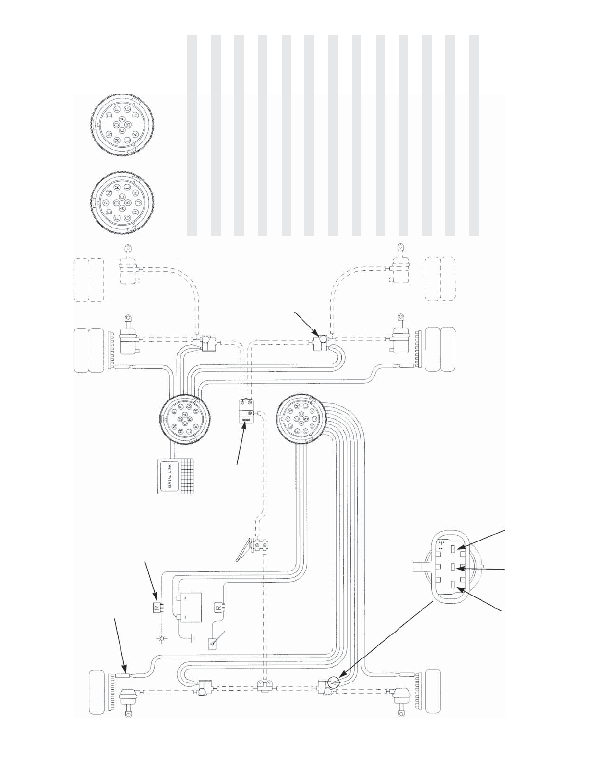
REAR
CONNECTOR 2
DEUTSCH CONNECTORSVEHICLE RIGHT FRONT
FRONT
CONNECTOR 1
CONNECTOR 2
TERMINAL TERMINAL CONNECTION
1J POWER
1K DASH LAMP (RELAY)
1P GROUND
™
EC-15
1N LEFT FRONT MODULATOR EXHAUST
1E LEFT FRONT MODULATOR HOLD
1M LEFT FRONT MODULATOR SOURCE
1F LEFT FRONT SPEED SIGNAL
CONTROLLER
1G LEFT FRONT SPEED SIGNAL RETURN
1B RETARDER DISABLE
™
M-21
MODULATOR
CONNECTOR 1
1C RIGHT FRONT MODULATOR EXHAUST
1A RIGHT FRONT MODULATOR HOLD
1D RIGHT FRONT MODULATOR SOURCE
1H RIGHT FRONT SPEED SIGNAL
1L RIGHT FRONT SPEED SIGNAL RETURN
2K LEFT REAR SPEED SIGNAL
2G LEFT REAR SPEED SIGNAL RETURN
2A LEFT REAR MODULATOR EXHAUST
2C LEFT REAR MODULATOR HOLD
2D LEFT REAR MODULATOR SOURCE
2M RIGHT REAR SPEED SIGNAL
2L RIGHT REAR SPEED SIGNAL RETURN
2E RIGHT REAR MODULATOR EXHAUST
2N RIGHT REAR MODULATOR HOLD
2F RIGHT REAR MODULATOR SOURCE
2B SERIAL A
2H SERIAL B
VEHICLE LEFT REAR
RELAY
SPEED SENSOR
CONTROL
DASH LAMP
RETARDER
FIGURE 7 - WIRING SCHEMATIC FOR EC-15™ CONTROLLER WITH DEUTSCH CONNECTORS
8
™
HOLD
SOURCE
CONNECTOR ON M-21
EXHAUST
MODULATOR
Page 9
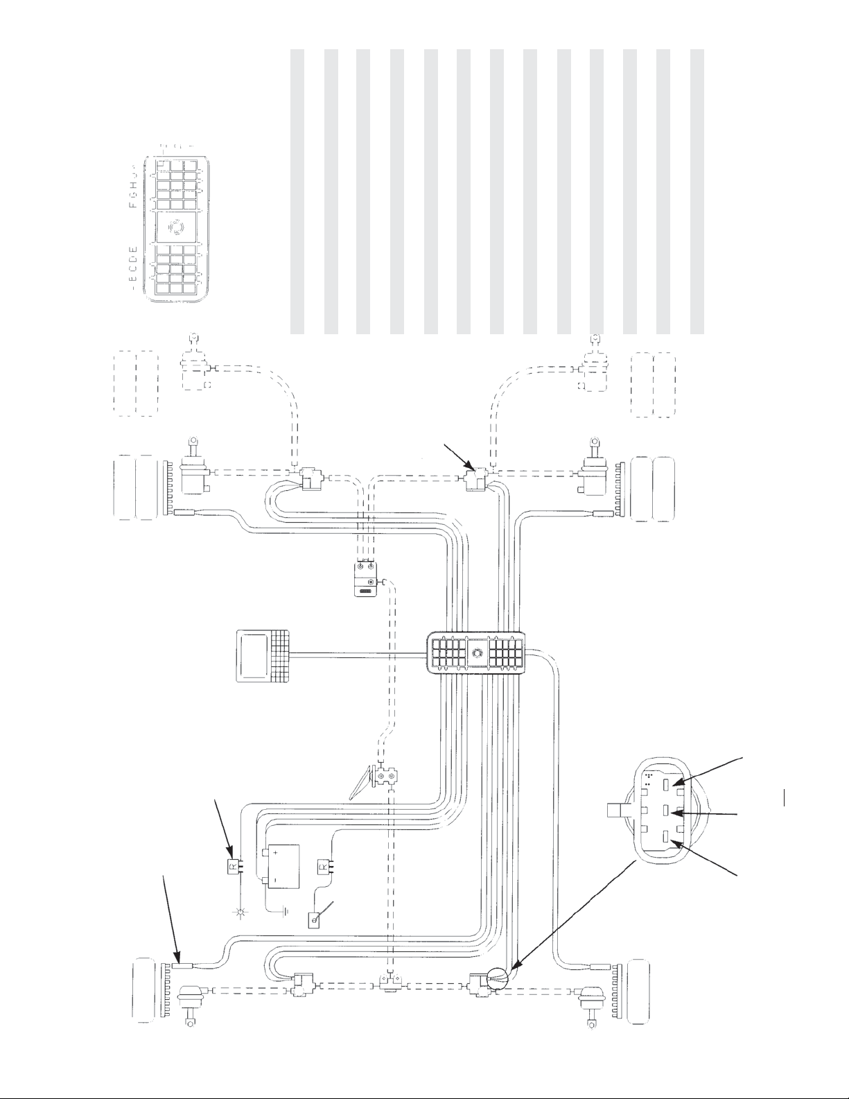
PACKARD CONNECTORVEHICLE RIGHT FRONT
TERMINAL TERMINAL CONNECTION
LINK
SERIAL
1K & 2K POWER
3F DASH LAMP (RELAY)
1A & 2A GROUND
2F LEFT FRONT MODULATOR EXHAUST
2G LEFT FRONT MODULATOR HOLD
1G LEFT FRONT MODULATOR SOURCE
3J LEFT FRONT SPEED SIGNAL
3H LEFT FRONT SPEED SIGNAL RETURN
3G RETARDER DISABLE
™
M-21
1H RIGHT FRONT MODULATOR EXHAUST
1J RIGHT FRONT MODULATOR HOLD
1F RIGHT FRONT MODULATOR SOURCE
MODULATOR
2H RIGHT FRONT SPEED SIGNAL
3K RIGHT FRONT SPEED SIGNAL RETURN
3E LEFT REAR SPEED SIGNAL
2C LEFT REAR SPEED SIGNAL RETURN
1B LEFT REAR MODULATOR EXHAUST
1C LEFT REAR MODULATOR HOLD
1D LEFT REAR MODULATOR SOURCE
3D RIGHT REAR SPEED SIGNAL
3C RIGHT REAR SPEED SIGNAL RETURN
2D RIGHT REAR MODULATOR EXHAUST
2E RIGHT REAR MODULATOR HOLD
1E RIGHT REAR MODULATOR SOURCE
3A SERIAL A
3B SERIAL B
2B NOT USED
2J NOT USED
VEHICLE LEFT REAR
RELAY
SPEED SENSOR
POWER
CONTROL
RETARDER
FIGURE 9 - WIRING SCHEMATIC FOR EC-15™ CONTROLLER WITH PACKARD CONNECTOR
™
HOLD
SOURCE
CONNECTOR ON M-21
EXHAUST
MODULATOR
9
Page 10

not to damage the gasket between the two components.
Peel the gasket from the EC-15™ controller or antilock
relay valve and retain for reuse. Note: Use a new
gasket if damaged during removal or if a new gasket
is immediately available.
™
BRACKET MOUNTED EC-15
1. Disconnect the electrical connector(s) from the EC-15
CONTROLLER
™
controller.
2. Note and mark the mounting position of the EC-15
™
controller on the vehicle. Loosen, remove and save
the nuts on the mounting hardware that attaches the
EC-15™ controller bracket to the vehicle. Remove the
EC-15™ controller and bracket from the vehicle.
3. Remove and retain the four cap screws that secure the
EC-15™ controller to the bracket. Separate the EC-15™
controller from the bracket.
INSTALLING THE EC-15™ CONTROLLER
ASSEMBLY
EC-15™ CONTROLLER MOUNTED ON ANTILOCK
RELAY VALVE
1. After noting the relationship of the positioning marks
made prior to disassembly, position the gasket on the
EC-15™ controller then secure the EC-15™ controller
to the antilock relay valve using the four cap screws.
Torque the cap screws to 50-80 lbs. in.
2. Mount the assembled EC-15™ controller and antilock
relay valve on the vehicle and orient it in the position
marked prior to removal.
3. Reconnect all air lines to the assembly.
4. Reconnect the electrical connector(s) to the EC-15™
controller.
5. Test the antilock relay valve for operation and leakage
prior to placing the vehicle in service.
6. Perform the “Initial Start-up Procedure” in the
TROUBLESHOOTING section to assure proper
antilock system operation.
BRACKET MOUNTED EC-15™ CONTROLLER
1. Secure the EC-15™ controller to its bracket using the
four cap screws. Torque the cap screws to 50-80 lbs.
in.
2. After noting the positioning marks, mount the EC-15
controller on the vehicle using the mounting hardware
retained during removal.
3. Connect the electrical connector(s) to the EC-15
controller.
™
™
4. Perform the “Initial Start-up Procedure” in the
TROUBLESHOOTING section to assure proper
antilock system operation.
DIAGNOSING AND LOCATING A SYSTEM
PROBLEM
GENERAL
The EC-15™ controller contains self test and diagnostic
circuitry that continuously checks for proper operation of
the entire antilock system including wiring continuity . A dash
lamp, controlled by the EC-15™ controller, advises the driver
of the condition of the entire antilock system. The condition
of specifi c antilock components is provided to the mechanic
by a series of labeled, light emitting diodes (LED’s)
displayed through a “window” in the EC-15™ controller
housing. No special tools or equipment are needed to read
or interpret the EC-15™ controller diagnostics window. It
should be noted that the EC-15™ controller diagnostics
display is separate from the antilock condition lamp on
the dash. With this separation, the driver is aware of any
problems that occur but is not confused by the diagnostic
information. A special feature of the EC-15™ controller is
the failure latching and diagnostic system. Intermittent
problems, particularly in the wheel speed sensing area
can be diffi cult to diagnose. When the controller senses an
erroneous condition, whether in the controller electronics,
the modulator or wheel speed sensing areas, it stores the
condition in non-volatile memory, disables the antilock
function, illuminates the dash mounted antilock condition
lamp and the appropriate diagnostic LEDs on the EC-15™
controller.
The failure condition is truly stored and is not cleared
by loss of power to the EC-15™ controller. The LEDs will
re-light when power is restored and remain illuminated
until the failure is corrected. After the actual problem is
corrected, maintenance personnel can clear or reset the
™
EC-15
over the RESET point in the diagnostics window.
DIAGNOSTIC LEDs
There are nine LEDs plus a magnetically actuated reset
switch in the EC-15
fi rst fi ve LEDs locate a problem to a specifi c area of the
vehicle while the last four indicate the problem component
or its wiring. The LEDs are software driven and are either
ON or OFF depending upon their monitor function. (Note:
Right and left, front and rear are determined from the
driver’s seat. Left front is therefore the corner closest to
the driver.)
controller diagnostics by passing a small magnet
™
controller diagnostic window. The
10
Page 11

LED o FRONT Red LED
LED o MID Red LED (SEE NOTE BELOW)
LED o REAR Red LED
LED o RIGHT Red LED
LED o LEFT Red LED
LED o MOD Red LED
LED o SENS Red LED
LED o ECU Red LED
LED o VOLT Green LED
III RESET No LED
NOTE: The MID LED shown in the chart above is not used
™
in the diagnostic process for the EC-15
controller
however it will light when a magnet is placed on the
RESET switch in the diagnostic window.
“LEFT” LED
This Red LED illuminates and latches ON in order to
indicate the location of a problem component or its wiring.
It will light in conjunction with either the FRONT or REAR
LED and the MOD or SENS LED.
“MOD” LED
This Red LED illuminates and latches ON to indicate
a permanent or intermittent open or short circuit in the
solenoids of one of the four modulators or the wiring
connecting it to the system.
“SENS” LED
FRONT
MID
REAR
RIGHT
LEFT
MOD
SENS
ECU
VOLT
RESET
EC-15™ CONTROLLER
DIAGNOSTIC WINDOW
“FRONT” LED
This Red LED illuminates and latches ON in order to
indicate the location of a problem component or its wiring.
It will light in conjunction with either the RIGHT or LEFT
LED and the MOD or SENS LED.
“MID” LED
This Red LED is not used in troubleshooting the EC-15
controller and should light only when a magnet is held on
the RESET switch.
™
This Red LED illuminates and latches ON to indicate
permanent or intermittent failure. The failures indicated
are; open or shorted wheel speed sensor, open or shorted
wheel speed sensor wiring, wheel speed signal not present
or does not conform to design criteria.
“ECU” LED
This Red LED, when illuminated, indicates that the
controller itself has failed. It is latched ON for all EC-15
controller failures except low voltage. For voltages less
than 9VDC, the LED illuminates to indicate the controller
is inoperative, however when the voltage again exceeds
9VDC the LED will go OUT by itself.
“VOLT” LED
This Green LED illuminates and remains ON during
vehicle operation to indicate that vehicle power is reaching
the controller. If vehicle power is out of range for proper
operation (below 1 1 vdc or above 17 vdc) this LED will fl ash
until power is brought into range.
“RESET”
Beneath the RESET area of the window display is a
magnetically sensitive switch that is used to reset the
diagnostic system. The device will respond to a magnet
which has strength suffi cient to lift a three (3) ounce weight.
Holding a magnet against the RESET will cause all LEDs
to light during the time the magnet is against it.
™
“REAR” LED
This Red LED illuminates and latches ON in order to
indicate the location of a problem component or its wiring.
It will light in conjunction with either the RIGHT or LEFT
LED and the MOD or SENS LED.
“RIGHT” LED
This Red LED illuminates and latches ON in order to
indicate the location of a problem component or its wiring.
It will light in conjunction with either the FRONT or REAR
LED and the MOD or SENS LED.
11
Page 12

TROUBLESHOOTING
GENERAL
While the EC-15™ controller diagnostic display locates
a specifi c problem area, it is still necessary to confi rm
whether the problem resides in the component itself or the
wiring. Basically the troubleshooting procedure that follows
is devoted to narrowing the problem to either the wiring or
a specifi c antilock component.
TROUBLESHOOTING TIPS
1. All troubleshooting begins by observing the antilock
condition lamp on the dash. Troubleshooting should
begin by fi rst performing the “Initial Start-up Procedure”
and following the directions contains in it.
2. The troubleshooting technician should record all
fi ndings and the action taken during the troubleshooting
process.
3. No voltage or resistance tests are performed into the
EC-15™ controller. All voltage and resistance tests
are performed by beginning at the wire harness half
of the connector and moving AWAY from the EC-15™
controller toward an antilock system component
(modulator, wheel speed sensor, etc.)
12
Page 13

START HERE
TROUBLESHOOTING
INITIAL START-UP PROCEDURE
TURN VEHICLE IGNITION ON.
OBSERVE DASH ANTILOCK
CONDITION LAMP.
IS DASH LAMP ILLUMINATED?
YES
DASH LAMP DOES NOT BLINK, IT COMES
ON AND REMAINS ON.
NO
DASH LAMP FLASHES AND COMES ON AND
STAYS ON. INCREASE VEHICLE SPEED TO
ABOVE 10 MPH FOR AT LEAST 30 SECONDS
AND OBSERVE THE DASH LAMP.
NO
YES
GO TO SECTION I
“DASH LAMP TESTING”
GO TO SECTION II
“INSPECTION FOR
ILLUMINATED LED(S)”
YES
DASH LAMP REMAINS ON
NO
THE SYSTEM IS FUNCTIONING NORMALLY.
MAKE NOTES OF THE PARTS REPLACED
OR REPAIRED AND STEPS TAKEN ON THE
TROUBLE SHOOTING SHEET.
GO TO SECTION III “INSPECTION
FOR ILLUMINATED LED(S)”.
13
Page 14
START HERE
TROUBLESHOOTING
SECTION I - DASH LAMP TESTING
DISCONNECT WIRE HARNESS CONNECTOR
FROM EC-15™ CONTROLLER (FRONT
CONNECTOR ONL Y IN FIGURE 7) AND OBSERVE
THE DASH LAMP.
DASH LAMP ILLUMINATED?
YES
NO
WITH IGNITION ON, MEASURE VOLTAGE BETWEEN
LAMP RELAY AND GROUND. VOLTAGE SHOULD BE
SAME AS BATTERY VOLTAGE (SEE FIGURES 7 AND 8)
NO
IS VOLTAGE CORRECT?
YES
REPLACE THE EC-15™
CONTROLLER
REPLACE FUSE
AND/OR REPAIR
OR REPLACE WIRE
HARNESS
14
CHECK WIRING HARNESS AND RELAY FOR
SHORTS TO GROUND. RECONNECT AND
CHECK/REPLACE THE FOLLOWING:
1. DASH LIGHT BULB
2. RELAY POWER WIRE
3. RELAY
AFTER REPLACING EACH COMPONENT
TEST THE DASH LAMP
REPEA T THE “INITIAL
START-UP PROCEDURE”.
Page 15
SECTION II - INSPECTION FOR ILLUMINATED LEDS
START HERE
TROUBLESHOOTING
INSPECT EC-15™
CONTROLLER FOR
PRESENCE OF
ILLUMINATED LEDS
AND RECORD.
NO
ARE ANY RED LEDS
ILLUMINATED?
YES
NOTE AND RECORD
THE CONDITION OF
ALL RED LEDS
NO
CHECK CLOSELY
AND NOTE IF GREEN
LED IS ILLUMINATED
ARE ANY
YES (ON)
RED LED’S
ILLUMINATED?
IS GREEN LED FLASHING?
YES
GO TO SECTION V “TESTING
FOR POWER TO THE EC-15™
CONTROLLER”.
NO (OFF)
NO
YES
REPLACE
THE EC-15™
CONTROLLER
GO TO SECTION
V “TESTING FOR
POWER TO THE
™
EC-15
CONTROLLER”
GO TO SECTION IV
“INSPECTION FOR
ILLUMINATED LEDS”.
GO TO SECTION VIII “TESTING
FOR FALSE FAILURE
INDICATION - CAUSED BY DASH
LAMP RELAY”.
15
Page 16
START HERE
TROUBLESHOOTING
SECTION III - INSPECTION FOR ILLUMINATED LED’S
INSPECT THE EC-15™ CONTROLLER
FOR PRESENCE OF ILLUMINATED
LEDS AND RECORD.
GO TO SECTION
V “TESTING
FOR POWER
™
TO THE EC-15
CONTROLLER”.
YES
IS GREEN, VOLT, LED
ILLUMINATED?
YES
IS GREEN LED FLASHING?
NO
ARE ANY RED LEDS
ILLUMINATED?
YES
NO
ARE ANY
RED LED’S
ILLUMINATED?
REPLACE THE
EC-15™ CONTROLLER
NO
GO TO SECTION IX “TESTING FOR
FALSE FAILURE INDICATION - CAUSED
BY WHEEL SPEED COMPONENTS”.
YES
GO TO SECTION
NO
V “TESTING
FOR POWER
TO THE EC-15™
CONTROLLER”.
16
NOTE AND RECORD
THE CONDITION OF
ALL RED LEDS
GO TO SECTION IV “INSPECTION
FOR ILLUMINATED LEDS”.
Page 17

TROUBLESHOOTING
SECTION IV - INSPECTION FOR ILLUMINATED LEDS.
START HERE
NOTE RED “ECU” LED IN
™
EC-15
CONTROLLER
DIAGNOSTICS WINDOW.
IS THIS LED ILLUMINATED?
NO
THERE MUST BE A MINIMUM OF THREE
RED LEDS ILLUMINATED AND OF THE
THREE THERE MUST BE A “RIGHT” OR
“LEFT”, PLUS A “FRONT” OR “REAR”, PLUS
A “MOD” OR “SENS”.
DO THE ABOVE CONDITIONS
EXIST?
NO
YES
GO TO SECTION V “TESTING
FOR POWER TO THE EC-15™
CONTROLLER”.
REPLACE THE EC-15™ CONTROLLER
AND REPEAT THE “INITIAL START-UP
PROCEDURE”.
YES
NOTE THE THREE
ILLUMINATED LEDS.
IS “MOD” LED ILLUMINATED
NO
THE “SENS” LED IS ILLUMINATED
USING THE TWO POSITIONING LEDS
(RIGHT/LEFT FRONT/REAR) GO TO
SECTION VIIA “TESTING THE WHEEL
SPEED SENSOR” AND TEST THE
APPROPRIATE SPEED SENSOR.
YES
USING THE TWO POSITIONING
LED’S (RIGHT/LEFT FRONT/REAR)
GO TO SECTION VIA “TESTING
THE MODULATOR” AND TEST THE
APPROPRIATE MODULATOR.
17
Page 18
START HERE
TROUBLESHOOTING
SECTION V - TESTING FOR POWER TO THE EC-15™ CONTROLLER
TURN IGNITION OFF, REFER TO FIGURES
7 AND 8, DISCONNECT WIRE HARNESS
CONNECTOR FROM EC-15™ CONTROLLER
(FRONT CONNECTOR ONLY IN FIGURE 7)
TURN IGNITION ON AND, MEASURE
VOLTAGE BETWEEN BATTERY AND
GROUND PINS ON WIRE HARNESS
CONNECTOR (SEE FIGURES 7 AND 8).
VOLTAGE SAME AS BATTERY
VOLTAGE, MUST BE BETWEEN
11 AND 17 VOLTS.
YES
REPLACE EC-15™
CONTROLLER
NO
RECONNECT CONNECTOR TO EC-15™
CONTROLLER. CHECK THE VEHICLE
WIRING FOR CONTINUITY. REFER TO
THE VEHICLE SERVICE MANUAL AND
CHECK THE BATTERY VOLTAGE.
REPAIR OR REPLACE AS NECESSARY
AND REPEAT THE “INITIAL START-UP
PROCEDURE”
REPEA T THE
“INITIAL START-UP
PROCEDURE”
18
Page 19
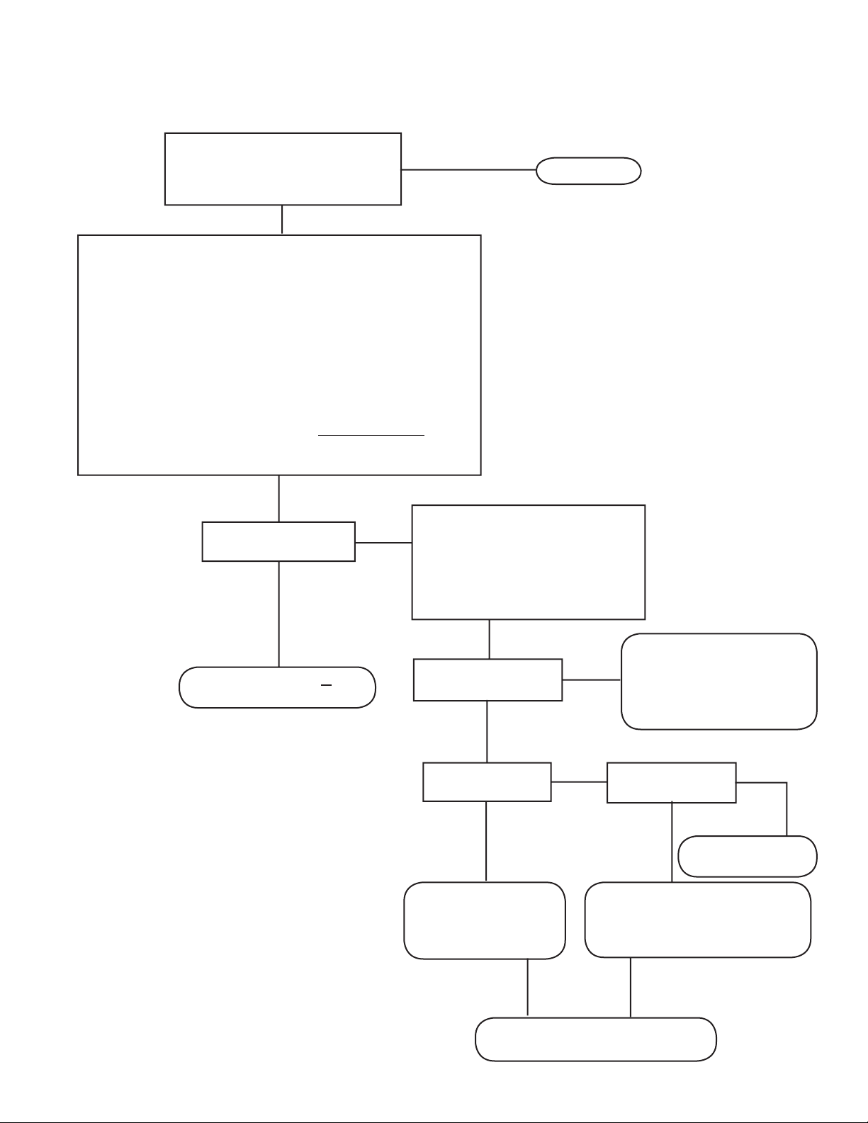
TROUBLESHOOTING
SECTION VI A - TESTING THE MODULATOR
TURN IGNITION OFF. REFER TO
FIGURES 7 AND 8. DISCONNECT
WIRE HARNESS CONNECTOR
FROM EC-15™ CONTROLLER.
PROBE CONNECTOR WITH VOLT/OHM METER AND NOTE
THAT PROPER RESISTANCE VALUES ARE OBTAINED FOR
MODULATOR BEING TESTED. FIGS. 7 AND 8. RESISTANCE
VALUES HERE FOR BENDIX® M-21™ MODULATOR (FIG. 5).
HOLD TO SOURCE: READ 3.5 TO 5 OHMS
EXHAUST TO SOURCE: READ 3.5 TO 5 OHMS
EXHAUST TO HOLD: READ 7 TO 10 OHMS
SOURCE TO BATTERY POWER: NO CONTINUITY
SOURCE TO GROUND: NO CONTINUITY
NOTE: SOURCE TO BATTERY TEST NOT REQUIRED FOR
CONNECTOR 2, (REAR) DEUTSCH CONNECTOR FIGURE 7.
START HERE
ARE RESISTANCE
VALUES CORRECT?
NO
GO TO SECTION VI B AND
CONTINUE TESTING
YES
INSPECT CONNECTOR AND
RECONNECT TO EC-15™
CONTROLLER. TURN IGNITION
ON AND PASS MAGNET OVER
RESET ON EC-15™ CONTROLLER.
NOTE REACTION OF RED LEDS.
REPEAT “INITIAL START-
ARE ANY RED LED’S
ILLUMINATED?
SAME RED LED’S
ILLUMINATED?
GO TO SECTION IV
“INSPECTION FOR
ILLUMINATED RED
LEDS” AND RETEST.
UP PROCEDURE”. IF THIS
TEST STEP HAS REPEATED
TWICE - REPLACE THE
EC-15™ CONTROLLER.
FRONT OR REAR
MODULATOR?
TEST REAR MODULATOR ON
OPPOSITE SIDE OF VEHICLE
GO TO BEGINNING THIS
SECTION (VI) AND RETEST
REPLACE EC-15™
CONTROLLER
IF FAILURE PERSISTS, REPLACE
THE EC-15™ CONTROLLER.
19
Page 20

START HERE FROM
SECTION VI A
TROUBLESHOOTING
SECTION VI B - TESTING THE MODULATOR
GO TO MODULATOR, INSPECT WIRING CONNECTOR.
DISCONNECT CONNECTOR AND TEST RESISTANCE
BETWEEN PINS ON MODULATOR, RESISTANCE VALUES
FOR BENDIX
HOLD TO SOURCE: READ 3.5 TO 5 OHMS
EXHAUST TO SOURCE: READ 3.5 TO 5 OHMS
EXHAUST TO HOLD: READ 7 TO 10 OHMS
TEST EACH PIN TO VEHICLE GROUND AND NOTE NO
CONTINUITY.
®
M-21™ MODULATOR (FIGURE 5).
RESISTANCE READINGS
NO
CORRECT?
YES
RECONNECT CONNECTOR TO MODULATOR.
TURN IGNITION ON AND PASS MAGNET OVER
RESET ON EC-15™ CONTROLLER. NOTE
REACTION OF RED LEDS.
ARE ANY RED LED’S
NO
ILLUMINATED?
YES
REPLACE THE MODULAT OR
REPEA T THE “INITIAL
START-UP PROCEDURE”
20
SAME RED LED’S
YES
ILLUMINATED?
NO
GO TO SECTION IV “INSPECTION FOR
ILLUMINATED LEDS” AND RETEST.
REPAIR OR REPLACE
MODULATOR WIRE HARNESS.
Page 21
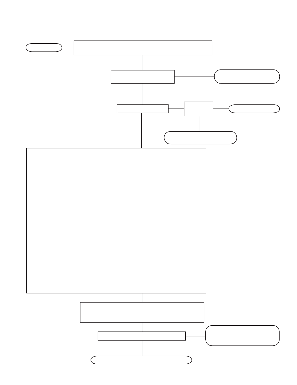
TROUBLESHOOTING
SECTION VII PART A - TESTING THE WHEEL SPEED SENSOR
START HERE
IGNITION ON, NOTE ILLUMINATED LED’S ON LOG SHEET.
DO MAGNETIC RESET, NOTE REACTION OF RED LED’S.
2ND TIME TO THIS POINT
YES
DURING TESTING?
NO
SAME RED
AND RED LED’S ON?
YES
LED’S ON?
YES
NO
GO TO SECTION VII PART
B AND BEGIN TESTING
TURN IGNITION OFF AND CHECK FOLLOWING:
A.
REMOVE CONNECTOR(S) FROM EC-15™ CONTROLLER AND MEASURE
RESISTANCE BETWEEN APPROPRIATE SPEED SENSOR SIGNAL (+) AND SIGNAL
RETURN (-). RESISTANCE FOR BENDIX® WS-20™ SPEED SENSOR IS BETWEEN
1500-2500 CHMS. REFER TO VEHICLE MAINTENANCE MANUAL IF OTHER
THAN THE WS-20™ SPEED SENSOR IS IN USE. (REFER FIG.8) IF RESISTANCE
NOT CORRECT, DISCONNECT CONNECTOR AT SPEED SENSOR. INSPECT
CONNECTOR, THEN CHECK RESISTANCE BETWEEN PINS ON SENSOR. IF
RESISTANCE IS NOT CORRECT (BETWEEN 1500-2500 OHMS FOR THE BENDIX®
WS-20™ SPEED SENSOR), REPLACE SENSOR, OTHERWISE PROCEED TO STEP B.
B. CHECK “GAP” BETWEEN SPEED SENSOR AND EXCITER OR TONE RING. (GAP
FOR BENDIX® WS-20™ SPEED SENSOR, SPEED SENDER IS BETWEEN
0 - .015 INCHES) IF SENSOR GAP MUST BE ADJUSTED, CHECK FOR LOOSE OR
WORN WHEEL BEARINGS BEFORE RE-GAPPING SENSOR. REFER TO VEHICLE
MAINTENANCE MANUAL FOR WORN BEARINGS.
C. IF SENSOR GAP IS CORRECT CHECK WHEEL BEARING FOR FREE PLAY TO
VERIFY IT COMPLIES TO MANUFACTURER’S RECOMMENDATIONS.
D. MAKE CERTAIN EXCITER OR TONE RING IS IN PLACE AND INSPECT CONDITION.
CHECK FOR MISSING OR DAMAGED TEETH AND THAT IT RUNS TRUE AND
PERPENDICULAR TO SENSOR FACE.
E. CHECK WIRING HARNESS AND CONNECTORS THAT RUN TO SENSOR.
F. CHECK FOR DRAGGING BRAKES (OVER ADJUSTED, TRAPPED AIR IN
ACTUATOR, OUT OF ROUND DRUMS, FAULTY RETURN SPRINGS, PARKING
BRAKE SYSTEM FAULTS, ETC.) AND CORRECT AND RETEST.
GO TO SECTION VII PART
B AND BEGIN TESTING
NO
GO TO SECTION IV
RECONNECT CONNECTORS AT EC-15
™
CONTROLLER AND SPEED SENSOR, DO MAGNETIC
RESET. NOTE RED LED’S.
ARE ANY RED LED’S ILLUMINATED?
YES
NO
GO TO “INITIAL START-UP PROCEDURE”
GO TO SECTION III
- “INSPECTION FOR
ILLUMINATED LED’S.”
21
Page 22

TROUBLESHOOTING
SECTION VI PART B - TESTING THE WHEEL SPEED SENSOR
START HERE FROM
SECTION VII P ART A
IGNITION OFF. REMOVE CONNECTOR(S) FROM EC-15™
CONTROLLER. MEASURE RESISTANCE BETWEEN THE
APPROPRIATE SPEED SIGNAL (+) AND SIGNAL RETURN (-).
RESISTANCE FOR BENDIX® WS-20™ SENSOR IS BETWEEN
1500-2500 OHMS. REFER TO VEHICLE MANUAL FOR THE
RESISTANCE VALUES IF OTHER THAN WS-20™ SENSOR
IS IN USE. (REFER TO FIGURE 7 & 8)
SAME LED’S ILLUMINATED?
YES
CORRECT RESISTANCE?
NO
NO
GO TO SECTION III “INSPECTION
FOR ILLUMINATED LEDS”.
YES
REPLACE EC-15™
CONTROLLER
DISCONNECT CONNECTOR AT SPEED SENSOR
INSPECT THE CONNECTOR, THEN CHECK THE
RESISTANCE BETWEEN TWO PINS ON SENSOR.
RESISTANCE BETWEEN 1500-2500 OHMS FOR
THE BENDIX® WS-20™ SPEED SENSOR.
YES
RECONNECT CONNECTOR AT SPEED
SENSOR AND EC-15™ CONTROLLER
AND DO MAGNETIC RESET. NOTE IF
ANY RED LEDS ARE ILLUMINATED.
ARE ANY LED’S ILLUMINATED?
YES
NO
ARE SAME RED LED’S ILLUMINATED?
NO
NO
REPLACE THE SENSOR
REPEA T THE “INITIAL
START-UP PROCEDURE”
GO TO SECTION III “INSPECTION
FOR ILLUMINATED LEDS”
22
YES
REPAIR OR REPLACE SPEED
SENSOR WIRING HARNESS.
Page 23
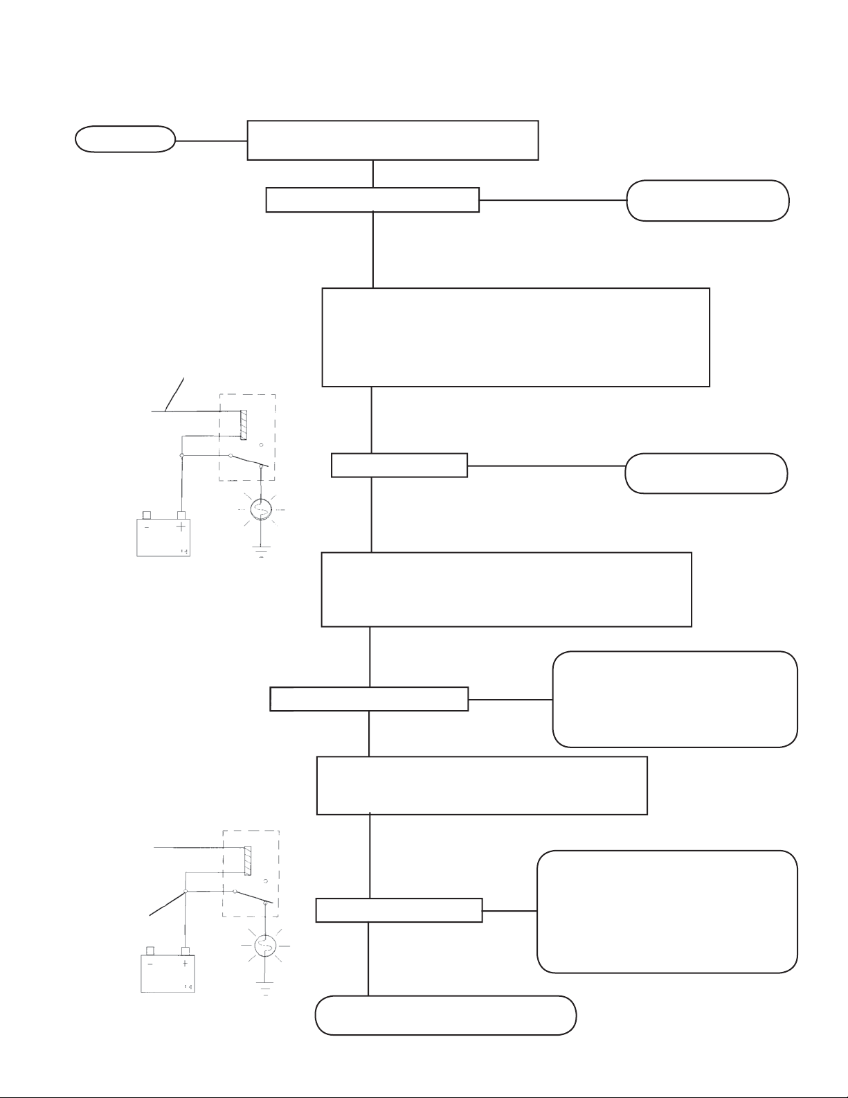
TROUBLESHOOTING
SECTION VIII - TESTING FOR FALSE INDICATION CAUSED BY DASH LIGHT RELAY
START HERE
TESTING THE LAMP RELAY
GROUND THIS WIRE AT
EC-15™ CONTROLLER
CONNECTOR
TO EC-15
™
CONTROLLER
CONNECTOR
LAMP
HOLD A MAGNET ON EC-15™ CONTROLLER
RESET AND NOTE ALL LEDS ILLUMINATED
ARE ALL LEDS ILLUMINATED?
YES
REMOVE MAGNET FROM EC-15™ CONTROLLER, TURN
IGNITION OFF AND DISCONNECT THE WIRING HARNESS
CONNECTOR(S) FROM EC-15™ CONTROLLER. TURN
IGNITION ON, GROUND LAMP RELAY WIRE (PIN 1K FIG. 7)
(PIN 3F FIG.8) AND NOTE DASH LAMP REACTION.
RELAY
DASH LAMP OFF?
NO
NO
YES
REPLACE EC-15™
CONTROLLER
REPLACE EC-15™
CONTROLLER
LAMP ON
CONTINUE
TESTING
TESTING THE LAMP RELAY
TO EC-15™
CONTROLLER
CONNECTOR
CHECK
FOR
POWER
HERE
TURN IGNITION OFF AND CHECK CONTINUITY OF
WIRING LAMP WIRE BETWEEN EC-15™ CONTROLLER
WIRING HARNESS CONNECTOR (SEE FIG. 7 & 8) AND
TERMINAL ON LAMP RELAY.
IS CONTINUITY DETECTED?
YES
RECONNECT THE EC-15™ CONTROLLER WIRE
HARNESS CONNECTOR(S), AND CHECK FOR
VEHICLE POWER AT THE LAMP RELAY COIL.
RELAY
IS POWER DETECTED?
LAMP
YES
NO
NO
REPAIR OR REPLACE WIRE
HARNESS. RECONNECT EC-15™
CONTROLLER WIRE HARNESS
AND REPEAT THE “INITIAL STARTUP PROCEDURE”
CHECK DASH WIRING AND
CONNECTORS, AND CONSULT THE
VEHICLE MANUAL FOR TROUBLE
SHOOTING INFORMATION. REPAIR
OR REPLACE AS NECESSARY AND
REPEAT THE “INITIAL START-UP
PROCEDURE”.
LAMP ON
BAD RELAY
REPLACE THE RELAY AND REPEAT
THE “INITIAL START-UP PROCEDURE”
23
Page 24
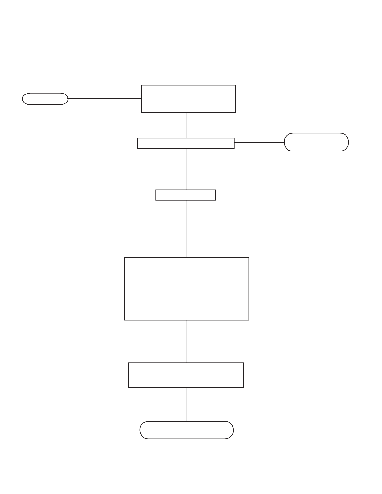
SECTION IX - TESTING FOR FALSE INDICATION CAUSED BY WHEEL SPEED COMPONENTS
START HERE
TROUBLESHOOTING
HOLD A MAGNET ON RESET
OF EC-15™ CONTROLLER
AND NOTE LEDS
ARE ALL LEDS ILLUMINATED?
YES
REMOVE MAGNET
TURN IGNITION OFF AND INSPECT
APPROPRIA TE AXLE AND WHEEL FOR
PRESENCE OF AN EXCITER OR TONE
RING AND SPEED SENSOR. CHECK THE
SENSOR “GAP” (DISTANCE BETWEEN
SPEED SENSOR AND EXCITER RING)
AND BEARING END PLAY. RE-ADJUST
AS NECESSARY.
NO
REPLACE EC-15™
CONTROLLER
24
RUN VEHICLE AT 10 MPH OR MORE
FOR 30 SECONDS OR MORE. TURN
OFF IGNITION
REPEAT “INITIAL START-UP
PROCEDURE”
BW1663 © 2008 Bendix Commercial Vehicle Systems LLC All rights reserved. 4/2008 Printed in U.S.A.
 Loading...