


 Loading...
2.4 GHz 54 Mbps
802.11g Wireless Cable/DSL Router
User Manual
ENGLISH
FRANÇAIS
DEUTSCH
NEDERLANDS
ESPAÑOL
ITALIANO
F5D7230ea4-E
P74847ea-A
Index |
|
ENGLISH ........................................................................................................... |
1 |
FRANÇAIS........................................................................................................ |
29 |
DEUTSCH......................................................................................................... |
59 |
NEDERLANDS.................................................................................................. |
89 |
ESPAÑOL ........................................................................................................ |
119 |
ITALIANO......................................................................................................... |
149 |

2.4 GHz 54 Mbps
802.11g Wireless Cable/DSL Router
User Manual
ENGLISH
F5D7230ea4-E
P74847ea-A
Trademarks:
Other product and company names are trademarks or registered trademarks of their respective holders.
Contents
About the IEEE 802.11g Wireless Router . . . . . . . . . . . . . . . . . . . . . . . . . . . 2
LED Indicators . . . . . . . . . . . . . . . . . . . . . . . . . . . . . . . . . . . . . . . . . . . . . . . 2 Features and Benefits . . . . . . . . . . . . . . . . . . . . . . . . . . . . . . . . . . . . . . . . . 3
Installing the IEEE 802.11g Wireless Router . . . . . . . . . . . . . . . . . . . . . . . . 4
Package Contents . . . . . . . . . . . . . . . . . . . . . . . . . . . . . . . . . . . . . . . . . . . . 4 Hardware Description . . . . . . . . . . . . . . . . . . . . . . . . . . . . . . . . . . . . . . . . . 5 System Requirements . . . . . . . . . . . . . . . . . . . . . . . . . . . . . . . . . . . . . . . . . 7 Connect the System . . . . . . . . . . . . . . . . . . . . . . . . . . . . . . . . . . . . . . . . . . 7 Basic Installation Procedure . . . . . . . . . . . . . . . . . . . . . . . . . . . . . . . . . 8 Configuring Client TCP/IP . . . . . . . . . . . . . . . . . . . . . . . . . . . . . . . . . . . . . 12 Configuring Your Computer in Windows 2000 . . . . . . . . . . . . . . . . . . 13 Configuring Your Computer in Windows XP . . . . . . . . . . . . . . . . . . . 16 Configuring a Macintosh Computer . . . . . . . . . . . . . . . . . . . . . . . . . . 17 Manual IP Configuration (for all Windows OS) . . . . . . . . . . . . . . . . . . 18 Verifying Your TCP/IP Connection . . . . . . . . . . . . . . . . . . . . . . . . . . . 20
Navigating the WEB browser Interface . . . . . . . . . . . . . . . . . . . . . . . . . . . 21
Connection Type . . . . . . . . . . . . . . . . . . . . . . . . . . . . . . . . . . . . . . . . . . . . 23 Dynamic . . . . . . . . . . . . . . . . . . . . . . . . . . . . . . . . . . . . . . . . . . . . . . . 23 Static . . . . . . . . . . . . . . . . . . . . . . . . . . . . . . . . . . . . . . . . . . . . . . . . . . 24 PPPoE . . . . . . . . . . . . . . . . . . . . . . . . . . . . . . . . . . . . . . . . . . . . . . . . . 24 PPTP . . . . . . . . . . . . . . . . . . . . . . . . . . . . . . . . . . . . . . . . . . . . . . . . . . 25
About the IEEE 802.11G Wireless Router
Congratulations on your purchase of the IEEE 802.11g Wireless Router. The F5D7230xx4-E is a powerful yet simple communication device for connecting your local area network (LAN) to the Internet.
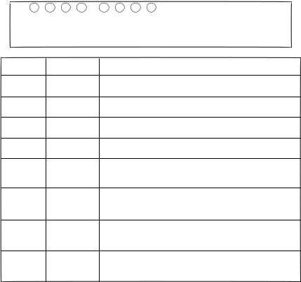
LED Indicators
The IEEE 802.11g Wireless Router includes status LED indicators, as described in the following figure and table.
LAN4 |
LAN3 |
LAN2 |
LAN1 |
LED Status
Power On
WAN On
Online On
WLAN On
Flashing
LAN1-4 Green On
Amber On
Flashing
Internet WLAN |
Power WAN |
IEEE 802.11g Wireless Router |
|
|
Description
The Wireless Router is receiving power.
The WAN link is connected.
PPP connection is on.
The Wireless LAN is enabled.
The Wireless Router is transmitting or receiving traffic via a wireless connection.
The indicated Ethernet port has established a valid 100 Mbps network connection.
The indicated Ethernet port has established a valid 10 Mbps network connection.
The indicated Ethernet port is transmitting or receiving traffic.
2
Features and Benefits
•Internet connection to DSL or cable modem via a 10/100 Mbps WAN port
•Local network connection via 10/100 Mbps Ethernet ports or 54 Mbps wireless interface
•IEEE 802.11g Compliant – interoperable with multiple vendors
•Advanced security through 64/128-bit WEP encryption, 802.1x, SSID broadcast disabled, and MAC address filtering features to protect your sensitve data and authenticate only authorized users to your network
•Provides seamless roaming within 802.11g WLAN environment
•DHCP for dynamic IP configuration, and DNS for domain name mapping
•Firewall with Stateful Packet Inspection, client privileges, hacker prevention, DoS, and NAT
•NAT also enables multi-user access with a single-user account, and virtual server functionality such as web, mail, FTP, and Telnet
•Virtual Private Network support using PPTP, L2TP, or IPSec pass-through, ISP permitting
•Parental controls allow the user to restrict web browsing
•Automatic email alerts when the network is being attacked
•Easy setup through a web browser on any operating system that supports TCP/IP
•Compatible with all popular Internet applications
3
Installing the IEEE 802.11G Wireless Router
Before installing the Wireless Router, verify that you have all the items listed under “Package Contents.” If any of the items are missing or damaged, contact your local distributor. Also be sure that you have all the necessary cabling before installing the Wireless Router. After installing the Wireless Router, refer to the web-based configuration program in “Configuring the IEEE 802.11g Wireless Router” on page 20 for information on configuring the Wireless Router.
Package Contents
After unpacking the Wireless Router, check the contents of the box to be sure you have received the following components:
•IEEE 802.11g Wireless Router
•Power adapter
•One CAT-5 Ethernet cable
•User guide
Immediately inform your dealer in the event of any incorrect, missing or damaged parts. If possible, please retain the carton and original packing materials in case there is a need to return the product.
For complete details on this products warranty, please refer to the Micradigital support site. www.micradigital.com
4
Hardware Description
The Wireless Router can be connected to the Internet or to a remote site using its WAN port. It can be connected directly to your PC or to a local area network using any of the Fast Ethernet LAN ports.
Although access speed to the Internet is determined by your service type and the modem type connected to the Wireless Router, data passing between the devices connected to your local area network can run up to 100 Mbps over the Fast Enternet ports.
The Wireless Router includes an LED display on the front panel for system power and port indications that simplifies installation and network
troubleshooting. It also provides four RJ-45 LAN ports and one RJ-45 WAN port on the rear panel.
•Four Ethernet ports for connection to a 10BASE-T/100BASE-TX Ethernet Local Area Network (LAN). These ports can auto-negotiate the operating speed to 10/100 Mbps, the mode to half/full duplex, and the pin signals to MDI/MDI-X (i.e., allowing these ports to be connected to any network device with straight-through cable). These ports can be connected directly to a
PC or to a server equipped with an Ethernet network interface card, or to a networking device such as an Ethernet hub or switch.
•One RJ-45 port for connection to a DSL or cable modem (WAN). This port also auto-negotiates operating speed to 10/100 Mbps, the mode to half/full duplex, and the pin signals to MDI/MDI-X.
The following figure shows the components of the Wireless Router:
5

Figure 1. Front and Rear Panels
Item |
Description |
|
|
LEDs |
Power, WLAN, WAN and LAN port status indicators. |
|
(See “LED Indicators” on page 1.) |
|
|
LAN |
Fast Ethernet ports (RJ-45). Connect devices (such as a PC, |
Ports |
hub or switch) on your local area network to these ports. |
|
|
Reset |
Use this button to reset the power and restore the default |
Button |
factory settings. |
|
|
WAN |
WAN port (RJ-45). Connect your cable modem, DSL modem, |
Port |
or an Ethernet router to this port. |
|
|
Power |
Connect the included power adapter to this inlet. |
Inlet |
Warning: Using the wrong type of power adapter may |
|
damage your Wireless Router. |
|
|
6
System Requirements
•Internet access from your local telephone company or Internet Service Provider (ISP) using a DSL modem or cable modem.
•A PC using a fixed IP address or dynamic IP address assigned via DHCP, as well as a gateway server address and DNS server address from your service provider.
•A computer equipped with a 10 Mbps, 100 Mbps, or 10/100 Mbps Fast Ethernet card, or a USB-to-Ethernet converter.
•TCP/IP network protocol installed on each PC that needs to access the Internet.
•A Java-enabled web browser, such as Microsoft Internet Explorer 5.5 or above, Firefox 1.0 or Mozilla 1.7 installed on one PC at your site for configuring the Wireless Router.
Connect the System
The Wireless Router can be positioned at any convenient location in your office or home. No special wiring or cooling requirements are needed. You should, however comply with the following guidelines:
•Keep the Wireless Router away from any heating devices.
•Do not place the Wireless Router in a dusty or wet environment.
You should also remember to turn off the power, remove the power cord from the outlet, and keep your hands dry when you install the Wireless Router.
7
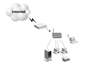
Basic Installation Procedure
1.Connect the LAN: Connect the Wireless Router to your PC, or to a hub or switch. Run Ethernet cable from one of the LAN ports on the rear of the Wireless Router to your computer’s network adapter or to another network device. You may also connect the Wireless Router to your PC (using a wireless client adapter) via radio signals.
2.Connect the WAN: Use an Ethernet cable for connecting the Wireless Router to a cable/xDSL modem or Ethernet router.
3.Power on: Connect the power adapter to the Wireless Router.
Internet
Access
Device
Wireless Router
Notebook with
Wireless PC Card
SOHO Office or Residence
Figure 2. Example Network Configuration
8

Attach to Your Network Using Ethernet Cabling
Use twisted-pair cable to connect any of the four LAN ports on the Wireless Router to an Ethernet adapter on your PC. Otherwise, you can cascade any of the LAN ports on the Wireless Router to an Ethernet hub or switch, and then connect your PC or other network equipment to the hub or switch. When inserting an RJ-45 plug, be sure the tab on the plug clicks into position to ensure that it is properly seated.
Warning: Do not plug a phone jack connector into any RJ-45 port. This may damage the Wireless Router. Instead, use only twisted-pair cables with RJ-45 connectors that conform with FCC standards.
Figure 3. Making a LAN Connection
9

Attach to Your Network Using Radio Signals
Install a wireless network adapter in each computer that will be connected to the Internet or your local network via radio signals.
Try to place the Wireless Router in a position that is located in the center of your wireless network. Normally, the higher you place the antenna, the better the performance. Ensure that the Wireless Router’s location provides optimal reception throughout your home or office.
A wireless infrastructure can be used for access to a central database, or for connection between mobile workers, as shown in the following figure:
Wired to Wireless
Network Extention
Internet
Access
Device Notebook with Wireless
PC Card Adapter
Wireless Router
PC with Wireless |
|
PCI Adapter |
Wired LAN |
Figure 4. WLAN Connection Example
10

Attach the IEEE 802.11g Wireless Router to the Internet
If Internet services are provided through an xDSL or cable modem, use unshielded or shielded twisted-pair Ethernet cable CAT 5 with RJ-45 plugs to connect the broadband modem directly to the WAN port on the Wireless Router.
DSL/Cable
Modem
ISP (Primary)
Figure 5. WAN Connection Example
Configuring Client TCP/IP
To access the Internet through the Wireless Router, you must configure the network settings of the computers on your LAN to use the same IP subnet as the Wireless Router. The default network settings for the Wireless Router are:
Gateway IP Address: 192.168.2.1
Subnet Mask: 255.255.255.0
Note: These settings may be changed to suit your network requirements, but you must first configure at least one computer as described in this chapter to access the Wireless Router’s web configuration interface. See “Configuring the IEEE 802.11g Wireless Router” on page 20 for information on configuring the Wireless Router.
The IP address of the connected client PC should be 192.168.2.x (where x means 2–254). You can set the IP address for client PCs either by automatically obtaining an IP address from the Wireless Router’s DHCP service or by manual configuration.
12
Configuring Your Computer in Windows 2000
1.Access your network settings by clicking Start, then choose Settings and then select Control Panel.
2.In the Control Panel, locate and double-click the Network and Dial-up Connections icon.
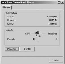
3.Locate and double-click the
Local Area Connection icon for the Ethernet adapter that is connected to the Wireless
Router. When the Status dialog box window opens, click the
Properties button.
4.In the Local Area Connection Properties box, verify the box next to Internet Protocol (TCP/ IP) is checked. Then highlight the
Internet Protocol (TCP/IP), and click the Properties button.
5.Select Obtain an IP address automatically to configure your
computer for DHCP. Click the OK button to save this change and close the Properties window.
6.Click the OK button again to save these new changes.
7.Reboot your PC.
8.To obtain new network settings see See “Obtain IP Settings from Your IEEE 802.11g Wireless Router” on the next page.
13

Obtain IP Settings from Your IEEE 802.11g Wireless Router
Now that you have configured your computer to connect to the Wireless Router, it needs to obtain new network settings. By releasing old IP settings and renewing them with settings from the Wireless Router, you will also verify that you have configured your computer correctly.
1.On the Windows desktop, click Start/Programs/Command Prompt.
2.In the Command Prompt window, type ipconfig /release and press the Enter key.
3.Type ipconfig /renew and press the Enter key. Verify that your IP Address is now 192.168.2.xxx, your Subnet Mask is 255.255.255.0 and your Default Gateway is 192.168.2.1. These values confirm that the Wireless Router is functioning.
4. Type exit and press Enter to close the Command Prompt window.
14

Configuring Your Computer in Windows XP
The following instructions assume you are running Windows XP with the default interface. If you are using the Classic interface (where the icons and menus look like previous Windows versions), please follow the instructions for Windows 2000 outlined above.
1.Access your Network settings by clicking Start, choose Control Panel, select Network and Internet Connections and then click on the Network Connections icon.
2.Locate and double-click the Local Area Connection icon for the Ethernet adapter that is connected to the Wireless Router. Next, click the
Properties button.
3.In the Local Area Connection Properties box, verify the box next to Internet Protocol (TCP/IP) is checked. Then highlight the Internet Protocol (TCP/IP), and click the Properties button.
4.Select Obtain an IP address automatically to configure your computer for DHCP. Click the OK button to save this change and close the Properties window.
5.Click the OK button again to save these new changes.
6.Reboot your PC.
15

Configuring a Macintosh Computer
You may find that the instructions here do not exactly match your screen. This is because these steps and screen shots were created using Mac OS 10.2. Mac OS 7.x and above are all very similar, but may not be identical to Mac OS 10.2.
1.Pull down the Apple Menu. Click System Preferences and select Network.
2.Make sure that Built-in Ethernet is selected in the Show field.
3.On the TCP/IP tab, select
Using DHCP in the Configure field.
4.Close the TCP/IP dialog box.
16
Manual IP Configuration (for all Windows OS)
1.Check Specify an IP address on the IP Address tab. Enter an IP address based on the default network 192.168.2.x (where x is between 2 and 254), and use 255.255.255.0 for the subnet mask.
2.In the Gateway tab, add the IP address of the Wireless Router (default: 192.168.2.1) in the New gateway field and click Add.
17
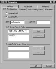
3.On the DNS Configuration tab, add the IP address for the Wireless Router and click Add. This automatically relays DNS requests to the DNS server(s) provided by your ISP. Otherwise, add specific DNS servers into the DNS Server Search Order field and click Add.
4.After finishing TCP/IP setup, click OK, and then reboot the computer. After that, set up other PCs on the LAN according to the procedures described above.
18
Verifying Your TCP/IP Connection
After installing the TCP/IP communication protocols and configuring an IP address in the same network as the Wireless Router, use the ping command to check if your computer has successfully connected to the Wireless Router. The following example shows how the ping procedure can be executed in an MS-DOS window. First, execute the ping command:
ping 192.168.2.1
If a message similar to the following appears:
Pinging 192.168.2.1 with 32 bytes of data:
Reply from 192.168.2.1: bytes=32 time=2ms TTL=64
a communication link between your computer and the Wireless Router has been successfully established.
If you get the following message,
Pinging 192.168.2.1 with 32 bytes of data:
Request timed out.
there may be something wrong in your installation procedure. Check the following items in sequence:
1.Is the Ethernet cable correctly connected between the Wireless Router and the computer?
The LAN LED on the Wireless Router and the Link LED of the network card on your computer must be on.
2. Is TCP/IP properly configured on your computer?
If the IP address of the Wireless Router is 192.168.2.1, the IP address of your PC must be from 192.168.2.2-254 and the default gateway must be 192.168.2.1.
If you can successfully ping the Wireless Router you are now ready to connect to the Internet!
19
Configuring the IEEE 802.11G Wireless Router
The IEEE 802.11g Wireless Router can be configured by Internet Explorer 5.5 or above. Using the web management interface, you can configure the Wireless Router and view statistics to monitor network activity.
Before you attempt to log into the web-based administration, please verify the following.
1.Your browser is configured properly (see below).
2.Disable any firewall or security software that may be running.
3.Confirm that you have a good link LED where your computer is plugged into the Wireless Router. If you don’t have a link light, then try another cable until you get a good link.
Browser Configuration
Confirm your browser is configured for a direct connection to the Internet using the Ethernet cable that is installed in the computer.
Disable Proxy Connection
You will also need to verify that the HTTP Proxy feature of your web browser is disabled. This is so that your web browser will be able to view the Wireless Router configuration pages. The following steps are for Internet Explorer.
Internet Explorer 5.5 or above (For Windows)
1.Open Internet Explorer. Click Tools, and then select Internet Options.
2.In the Internet Options window, click the Connections tab. Navigating the Web Browser Interface
3.Click the LAN Settings button.
4.Clear all the check boxes and click OK to save these LAN settings changes.
5.Click OK again to close the Internet Options window.
20

Internet Explorer (For Macintosh)
1.Open Internet Explorer. Click Explorer/Preferences.
2.In the Internet Explorer Preferences window, under Network, select
Proxies.
3.Uncheck all check boxes and click OK.
Navigating the Web Browser Interface
1.To access the Wireless routers management interface, enter the address or the wireless router in the address bar of your web browser: http://192.168.2.1
2.You are required to Log in before you can proceed any further. Click on the Login button on the top right hand side of the screen. By default the password is blank so you can just click the ‘Submit’ button
21

3.To set-up the Internet connection, In Menu list on the left hand side of the screen, locate the option ‘Connection Type’ which can be found under the ‘Internet WAN’ category
4.WAN > Connection type screen allows you to select the connection type needed to make a connection to your Internet Service Provider (ISP). Please consult the information provided by you ISP to make sure you make the correct selection. Once you have selected the correct Connection type, click on ‘Next’
22
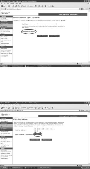
Connection Type
a. Dynamic:
Your Internet Service Provider may have given you a host name. If so enter it into the field.
If your ISP used the Mac Address of an Ethernet card as an Identifier when first setting up your broadband account click on the button ‘Change WAN MAC address’ It is important to note that you should only connect the computer with the registered MAC address to the router during configuration.
Click on the button marked ‘Clone‘ to replace the Wireles router MAC address with the one from your computers Ethernet card, which is registered with your ISP.
23
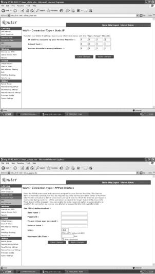
b. Static:
If your Internet Service provider has given you your own IP address choose this option and fill in the details in the relevant fields
c. PPPoE:
Enter the PPPoE User Name and Password assigned by your Service Provider. The Service Name is normally optional, but may be required by some service providers.
Leave the Maximum Transmission Unit (MTU) at the default value (1454) unless you have a particular reason to change it.
Enter a Maximum Idle Time (in minutes) to define a maximum period of time for which the Internet connection is maintained during inactivity. If the connection is inactive
for longer than the Maximum Idle Time, it will be dropped. (Default: 3 minutes)
24
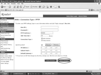
d. PPTP:
If your ISP has specified this connection type for making the connection to the internet. Enter the details in the relevant fileds and click on the Apply Changes button
If you have been provided with the information as shown on the screen, enter the PPTP Account name and password, Host Name, Service IP Address, the assigned IP Address, and Subnet Mask.
Leave the Maximum Transmission Unit (MTU) at the default value (1460) unless you have a particular reason to change it.
Enter a Maximum Idle Time (in minutes) to define a maximum period of time for which the Internet connection is maintained during inactivity. If the connection is inactive for longer than the Maximum Idle Time, it will be dropped. (Default:
3 minutes)
Note: If you are on a leased line or pay-per min. connection, please set your maximum idle time to 3 minutes. This will cause your Internet
connection to drop after 3 minutes of idle time so you won’t be charged for extra online time from your ISP.
Click FINISH to complete the setup.
26
Loading...