


DEC 1-30S
Beko DEC 1-30S, DEC 2-40S, DEC 3-60S, DEC 4-80S, DEC 5-115S Installation And Operational Manual
...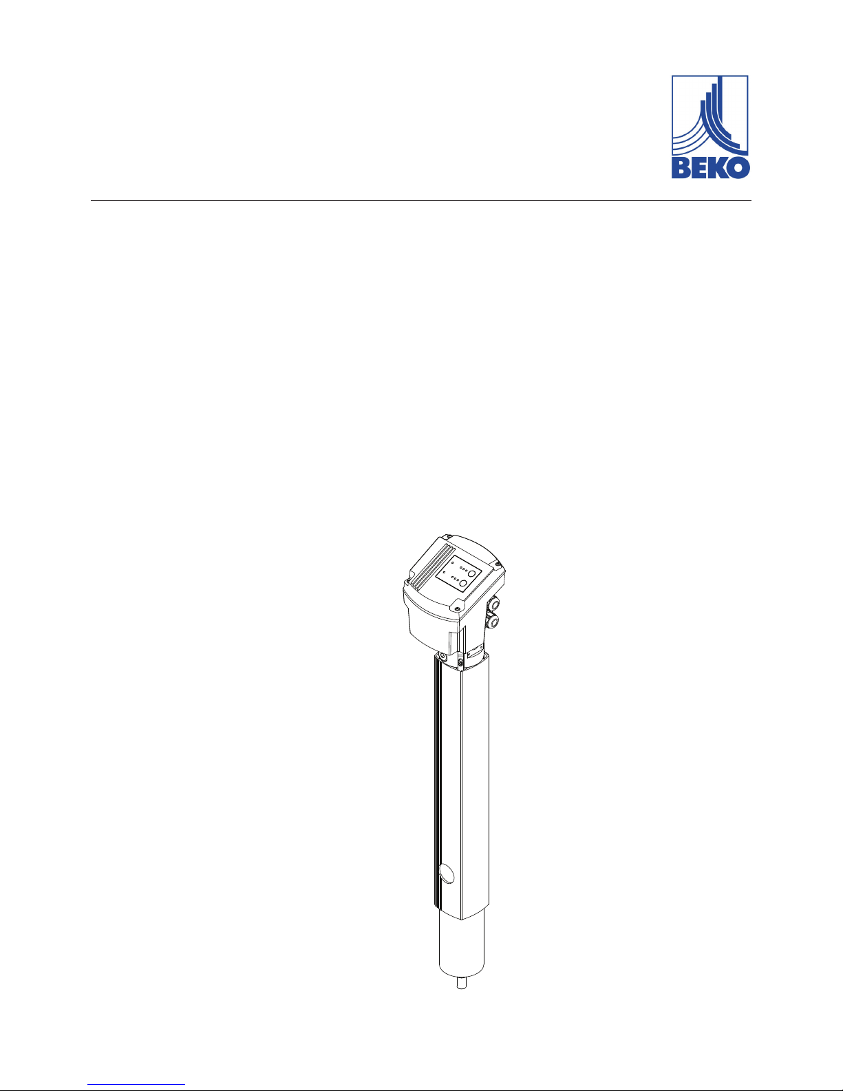
DRYPOINT® M eco control
DEC 1-30S
DEC 2-40S
DEC 3-60S
DEC 4-80S
DEC 5-115S
DEC 6-135S
DEC 7-165S
DEC 8-250S
DEC 9-330S
Drying system
Installation and operation manual
EN - English
07-068

Installation and operation manual EN
2 DRYPOINT® M eco control
Contents
1. Safety-related information .............................................................................................................................. 4
1.1. Pictograms and symbols .......................................................................................................................... 4
1.1.1. In this documentation ........................................................................................................................................................4
1.1.2. On the device .......................................................................................................................................................................4
1.2. Signal words according to ISO 3864 and ANSI Z.535 ................................................................................ 5
1.3. Safety instructions .................................................................................................................................. 5
1.4. Transport and storage ............................................................................................................................. 6
1.5. Intended use ........................................................................................................................................... 7
1.6. Warranty and liability for defects ............................................................................................................ 7
2. Product information ....................................................................................................................................... 8
2.1. Scope of delivery .................................................................................................................................... 8
2.2. Type plate ............................................................................................................................................... 8
2.2.1. Rating plate for the drying system ..................................................................................................................................8
2.2.2. Rating plate for control unit .............................................................................................................................................9
2.3. Product overview and description ......................................................................................................... 10
2.4. Parts and components ........................................................................................................................... 11
2.4.1. Principle function methods ............................................................................................................................................ 12
2.4.2. Operating mode ...............................................................................................................................................................13
2.5. Control and display elements ................................................................................................................ 14
2.6. 4 ... 20 mA interface .............................................................................................................................. 15
2.7. Alarm relay ........................................................................................................................................... 15
2.8. Dimensions ........................................................................................................................................... 16
2.9. Technical data ....................................................................................................................................... 17
3. Assembly ...................................................................................................................................................... 21
3.1. Prerequisites ........................................................................................................................................ 21
3.2. Assembly steps ..................................................................................................................................... 22
4. Electrical installation .................................................................................................................................... 23
4.1. Warning ................................................................................................................................................ 23
4.2. Terminal positions................................................................................................................................. 23
4.3. Opening the control unit ....................................................................................................................... 24
4.4. Connection of voltage power cable to power supply board ..................................................................... 25
4.5. Connection of 4 ... 20 mA interfaces on the control unit PCB .................................................................. 25
4.6. Connection of equipotential contact on the control unit PCB ................................................................. 25
5. Commissioning ............................................................................................................................................. 25
6. Operation ..................................................................................................................................................... 26
6.1. Indicators in operation .......................................................................................................................... 26
6.2. Solenoid valve test function .................................................................................................................. 27
6.3. Acquiring settings (set-up mode) .......................................................................................................... 27
6.3.1. Amend the operating mode ........................................................................................................................................... 27
6.3.2. Altering the values ........................................................................................................................................................... 27
6.3.3. Service mode ..................................................................................................................................................................... 28
7. Maintenance and servicing............................................................................................................................ 28

EN Installation and operation manual
DRYPOINT® M eco control 3
7.1. Maintenance schedule .......................................................................................................................... 28
7.1.1. Function and visual inspections .................................................................................................................................... 28
7.1.2. Filter element maintenance ........................................................................................................................................... 29
7.1.3. Exchanging the control unit ........................................................................................................................................... 30
7.1.4. Replacing the oat drain-o conduit ........................................................................................................................... 34
7.1.5. Wear part exchange ......................................................................................................................................................... 35
7.1.6. Measuring the permeation rate .................................................................................................................................... 42
7.1.7. Cleaning .............................................................................................................................................................................. 43
8. Spare parts and accessories ........................................................................................................................... 43
9. Remedying malfunctions, errors, faults and troubleshooting ......................................................................... 44
9.1. Behaviour in the event of malfunctions/errors, faults ............................................................................ 44
9.1.1. Failure of the voltage power supply ............................................................................................................................. 44
9.1.2. Sensor failure ..................................................................................................................................................................... 44
9.1.3. Deviating degree of drying ............................................................................................................................................ 45
9.2. FAQ ...................................................................................................................................................... 46
10. Decommissioning ....................................................................................................................................... 48
11. Dismantling and disposal ............................................................................................................................ 48
12. Declaration of Conformity .......................................................................................................................... 49
Installation and operation manual EN
4 DRYPOINT® M eco control
1. Safety-related information
1.1. Pictograms and symbols
1.1.1. In this documentation
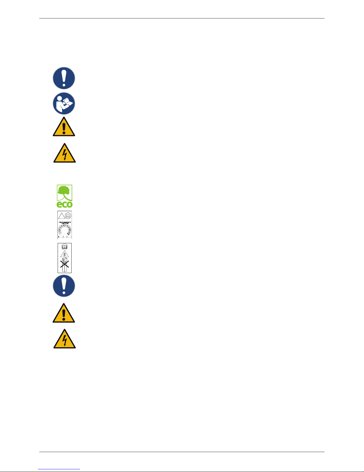
General instructions
Observe installation and operating instructions
General hazard symbol (danger, warning, caution)
General hazard symbol (danger, warning, caution) for mains voltage
and mains voltage energised plant and system parts
1.1.2. On the device
eco label
Symbol for particularly energy-ecient devices
!
20.. 20.. 20..
Maintenance information for nanolter:
Details relating to next required lter exchange
Maintenance information for nanolter:
Never open the housing lid when exchanging the lter
General instructions
General hazard symbol (danger, warning, caution)
General hazard symbol (danger, warning, caution) for mains voltage
and mains voltage energised plant and system parts
EN Installation and operation manual
DRYPOINT® M eco control 5
1.2. Signal words according to ISO 3864 and ANSI Z.535
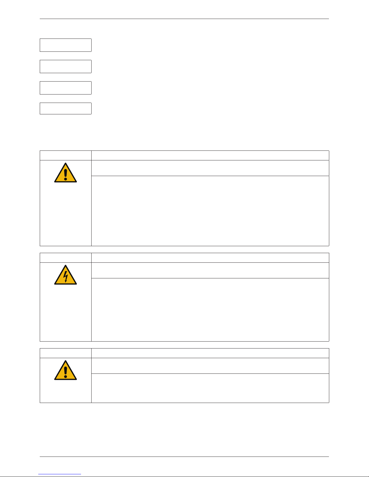
DANGER!
Imminent danger
Consequences of non-compliance: serious or even fatal injury
WARNING!
Potential danger
Consequences of non-compliance: possibly serious or even fatal injury
CAUTION
Imminent danger
Consequences of non-compliance: injury and/or damage to property
NOTE
Additional notes, information, tips
Consequences of non-compliance: Disadvantages during operation and maintenance.
No risk to persons.
1.3. Safety instructions
DANGER! Escaping compressed gas
Risk of serious or even fatal injury from suddenly released compressed gas, condensate or
unsecured system components.
• Before carrying out any assembly, installation or maintenance work, depressurise the system.
These works may only be executed by authorised specialist technical personnel1.
• Use only pressure-resistant installation materials and suitable tools that are in proper working
order.
• Before pressurising the system, check all unit parts and repair them, if necessary. Open valves
slowly to prevent pressure blow outs during operation.
• Always prevent people or objects from being aected by condensate or escaping compressed
gas.
• Prevent vibrations, oscillations and impact from being transferred to system parts.
• Perform a leakage test.
DANGER!
Mains voltage
Risk of electric shock with serious or even fatal injuries if contact is made with non-insulated, live
components.
• Observe all applicable regulations with respect to electrical installations (e.g. VDE 0100 / IEC
60364).
• Only execute installation and maintenance works when the system has been deenergised.
• Electrical works may only be executed by authorised specialist technical personnel1.
• Read o the permissible operating voltage on the rating plate and always comply with it.
• Only utilise components for the electrical installation which have a current approval
and are labelled with a CE-Identication Marking.
• A safely accessible circuit breaker (e.g. power plug or switch) must be provided close to the unit
for disconnecting all current and/or power lines for the voltage supply.
WARNING! Operating outside of limits
If the specied limits are undershot and/or exceeded, there is a risk of device malfunction,
potentially resulting in injury and/or damage to property.
• The device must only be operated for the intended purpose and within the permissible limits
specied on the type plate and in the technical data.
• Strictly adhere to the prescribed operating times and maintenance intervals.
• Strictly adhere to the prescribed storage and transport conditions.
1
Specialist technical personnel
Specialist technical personnel are people who, due to their professional qualication and knowledge in the eld of
measuring, control and pneumatic technology, and their knowledge of the applicable statutory regulations, guidelines
and standards are in a position to independently foresee potential dangers in relation to the use of the device and who
are qualied to perform the tasks described in this manual. Special operating conditions (e.g. aggressive media) require
additional knowledge.
Installation and operation manual EN
6 DRYPOINT® M eco control
1.4. Transport and storage
Despite our best eorts regarding packaging etc., the device might be damaged during transport. Please therefore remove
all packaging material immediately after receipt and inspect the product for any possible transport damage. Any damages
must be immediately notied to the transport company and BEKO TECHNOLOGIES GMBH or one of their agents.
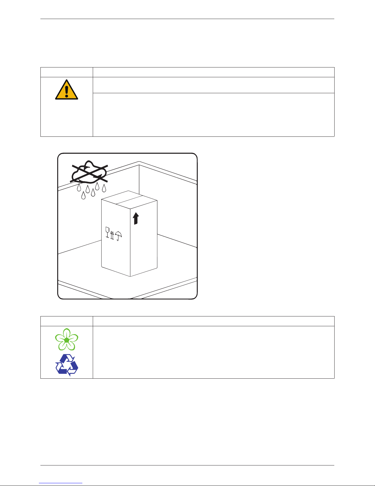
CAUTION Damage caused during transport or storage
Incorrect transport or storage, or the use of unsuitable lifting equipment, might cause damage to
the device.
• The device must only be transported and stored by authorised and suitably trained technical
personnel.
• If you detect any damage, do not start the device.
• Always comply with the permissible storage and transport temperatures (refer to technical
data).
• Never expose the device to continuous, direct sunlight or heat radiation.
The device must be stored in the original
packaging. Seal the packaging and store it in a
dry and frost-free room. Ensure that the ambient
conditions do not fall below or exceed the limits
specied on the type plate.
Always take suitable measures to protect the
device against the elements even in a packaged
condition.
While in storage, secure the device so that it
cannot topple over or fall, and protect it against
vibration.
NOTE Recycling packaging material
• The packaging material is recyclable. Dispose of the packaging material according to the
applicable statutory regulations.

EN Installation and operation manual
DRYPOINT® M eco control 7
1.5. Intended use
The DRYPOINT® M eco control drying system with integrated nanolter and pressure dew point control is designed for the
removal of aerosols and particles from compressed air and subsequent targeted drying of the air according to the individual
settings by the user.
Operate the DRYPOINT® M eco control only for the intended purpose and within the limit range specied in the technical
data. Do not operate the unit with any media (uids, gas/vapour mixtures) other than those listed above. Any other use
of this system, which exceeds the intended use, is hereby deemed to be improper and can cause a hazard for the safety of
people and the environment.
• Operating the unit may only be executed within the permissible operating parameter limits (refer to technical data).
• Operating pressure will be required for the proper functional operation.
• The device is not suitable for operation in explosion hazard areas as well as in areas with aggressive atmospheres.
• Do not operate the device with corrosive gases.
• Strictly observe the prescribed storage and transport conditions.
• The device is not suitable for use in conjunction with CO² systems.
The operating company must establish measures for the monitoring of the compressed air quality when using industrial
processes with higher quality requirements (e.g. food industry, medical technology, laboratory equipment, special processes,
etc.). These inuence the safety for subsequent processes and can prevent injuries to people and damage to plants and
systems. It is the duty of the owner and/or operator to always comply with the stated conditions during the entire operating
time.
1.6. Warranty and liability for defects
All liability claims will be deemed to be invalid when the DRYPOINT-M® eco control is not utilised in accordance with its
intended use or is operated outside the specifications stated in the technical data, this particularly includes:
• Technically incorrect installation, incorrect commissioning, incorrect maintenance or incorrect operation
• Operation with defective components
• Non-compliance with the instructions in this manual, in particular the safety instructions
• Execution of constructive interventions or modications on the device
• Non-compliance with the prescribed maintenance intervals
• Use of third-party spare parts that have not been approved by the manufacturer for repair and maintenance works
Installation and operation manual EN
8 DRYPOINT® M eco control
2. Product information
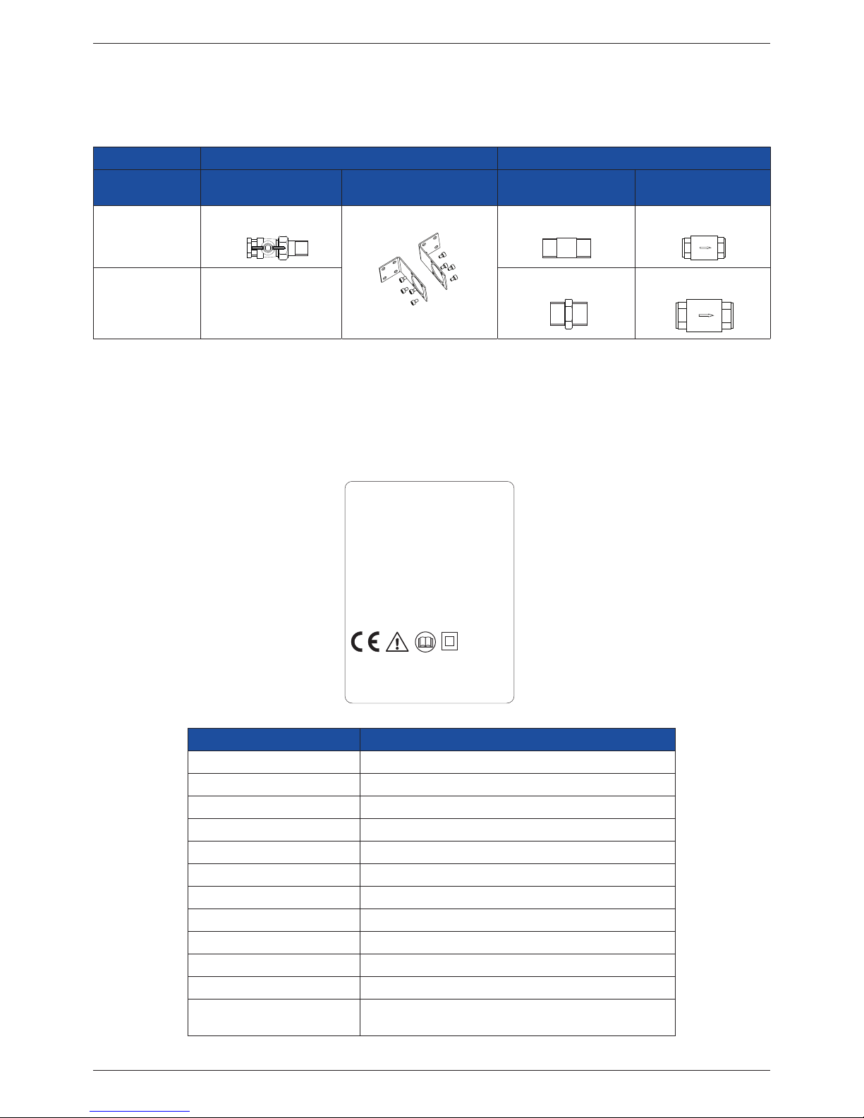
2.1. Scope of delivery
The following table indicates the scope of delivery for the DRYPOINT® M eco control.
Inlet side Outlet side
Model Ball valve Wall bracket Long nipple/double
nipple
Non-return valve
DEC 1 ... DEC 6
G 1/2 G 1/2 G 1/2
DEC 7 ... DEC 9
-
G 1 G 1
2.2. Type plate
The drying system is equipped with two rating plates: One rating plate for the entire system and one rating plate for the
control unit.
2.2.1. Rating plate for the drying system
DRYPOINT® M eco control
BEKO TECHNOLOGIES
Made in Germany
www.beko-technologies.com
Type: DEC6-135S
Material-no.: 4039476
Serial-no.: 13434090
Lot: 201621
Element: 06N-V02
Element mat.-no.: 4010849
Work. temp. TS:
+2 ... 50 °C / +35 ... 122 °F
Max. work. pr. PS: 4 ... 10 bar / 58 ... 145 psi
Connection: pipe G
1/2
Power supply: 95 ... 240 VAC ± 10 %
50-60 Hz, max. 20 VA(W)
100 ... 125 VDC ± 10 %
Protection-Class: PED2014/68/EU/Category - Fluidgroup 2
DRYPOINT
Designation Description
Model: Model designation
Material No.: Material number
Serial No.: Serial number
Batch: Date of manufacture
Element: Designation for integrated lter element
Element mat.-no.: Material number for integrated lter element
Work. temp. TS: Permissible minimum/maximum operating temperature
Maximum. working pr. PS: Permissible minimum/maximum operating pressure
Connection: Thread information pipe connection
Power supply: Data for voltage supply
Protection-Class: IP protection class
PED2014/68/EU/Category Permissible uid group according to European Pressure
Equipment Directive
EN Installation and operation manual
DRYPOINT® M eco control 9
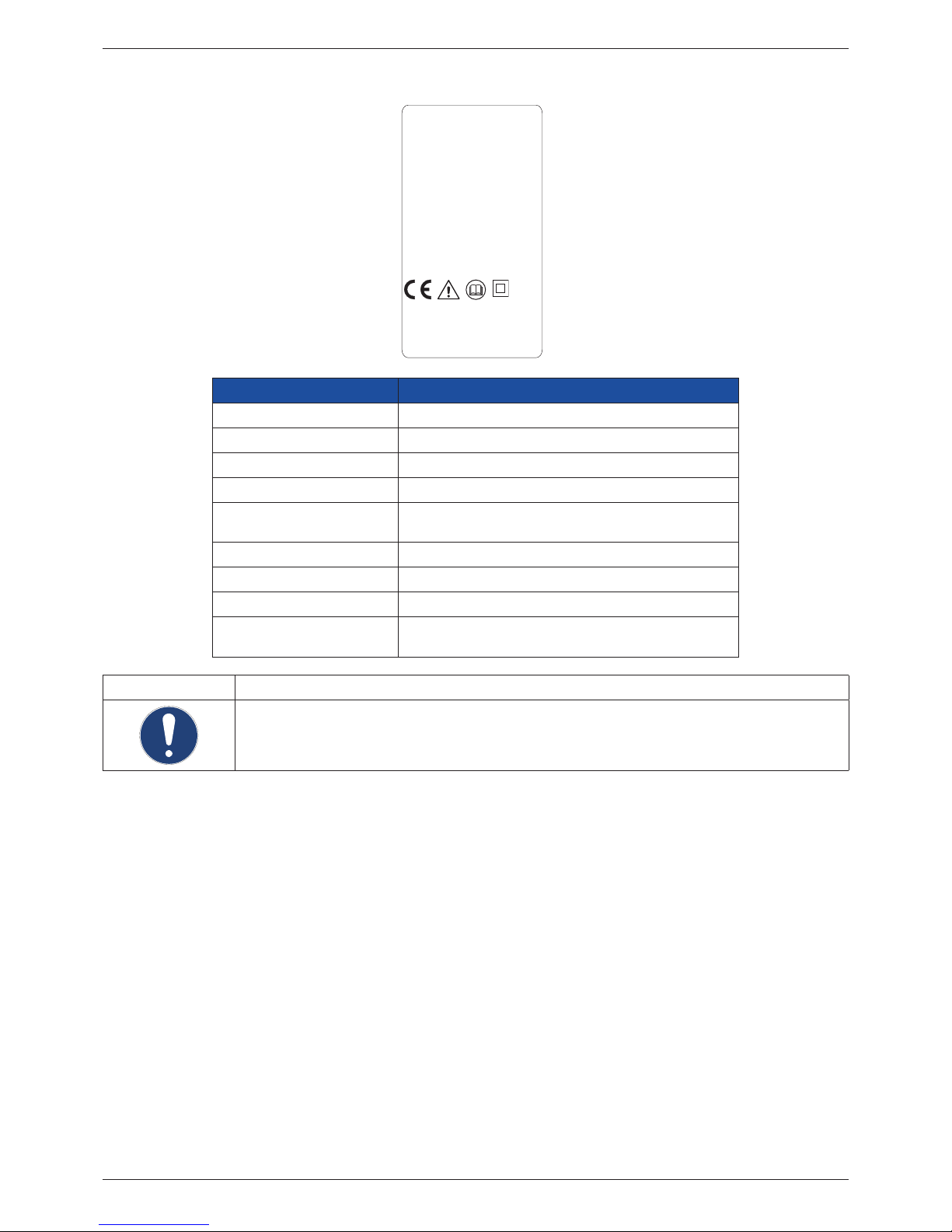
2.2.2. Rating plate for control unit
DEC Control Unit
BEKO TECHNOLOGIES
Made in Germany
www.beko-technologies.com
Type: DEC-CU135S
Material-no.: 4039455
Serial-no.: 13434090
Lot: 201621
Work. temp. TS:
+2 ... 50 °C / +35 ... 122 °F
Max. work. pr. PS:
4 ... 10 bar / 58 ... 145 psi
Power supply:
95 ... 240 VAC ± 10 %, 50-60 Hz
100 ... 125 VDC ± 10 % / max. 20 VA(W)
Protection-Class: IP 54
PED2014/68/EU/
Cat. - /Fluidgroup 2
DRYPOINT
Designation Description
Model: Model designation
Material No.: Material number
Serial No.: Serial number
Batch: Date of manufacture
Work. temp. TS: Permissible minimum/maximum operating
temperature
Maximum. working pr. PS: Permissible minimum/maximum operating pressure
Power supply: Data for voltage supply
Protection-Class: IP protection class
PED2014/68/EU/Category Permissible uid group according to European
Pressure Equipment Directive
NOTE Handling of type plate
Never damage, remove or make the type plate illegible.
For more information regarding the symbols printed on the type plate, see “Pictograms and symbols”
on Page 4.
Installation and operation manual EN
10 DRYPOINT® M eco control
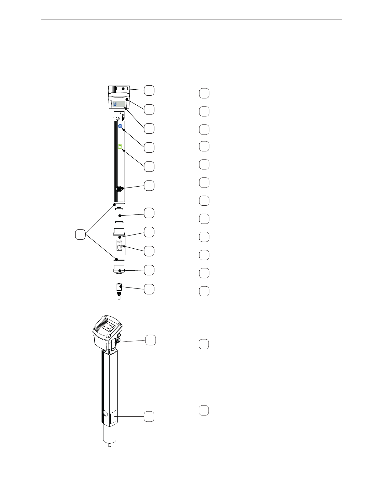
2.3. Product overview and description
The DRYPOINT® M eco control is a drying system that guarantees a constant degree of drying even under uctuating
operating conditions. The sensor system integrated into the control unit (2) reacts to uctuating operating pressure, inlet
pressure dew point as well as dierential requirements for compressed air quantities. The display and control elements are
integrated into the control panel (1). The operating modes as well as specied degree of drying are displayed here. A change
of the operating mode or the degree of drying is always possible during running operation.
1
2
3
4
8
5
7
9
6
11
12
10
!
20.. 20.. 20..
Year
Month
NEXT ELEMENT
CHANGE
DRYPOINT® M
eco control
1
User interface
2
Control unit/housing head
3
Label: DRYPOINT® M eco control
4
Label: BEKO quality
5
Labels: eco label
6
Purge air outlet
7
Nanolter element
8
O-rings (housing)
9
Housing extension
10
Label: Next element change
11
Housing base
12
Float drain-o conduit
13
14
13
Rating plate for the control unit
14
Rating plate for the drying system
EN Installation and operation manual
DRYPOINT® M eco control 11
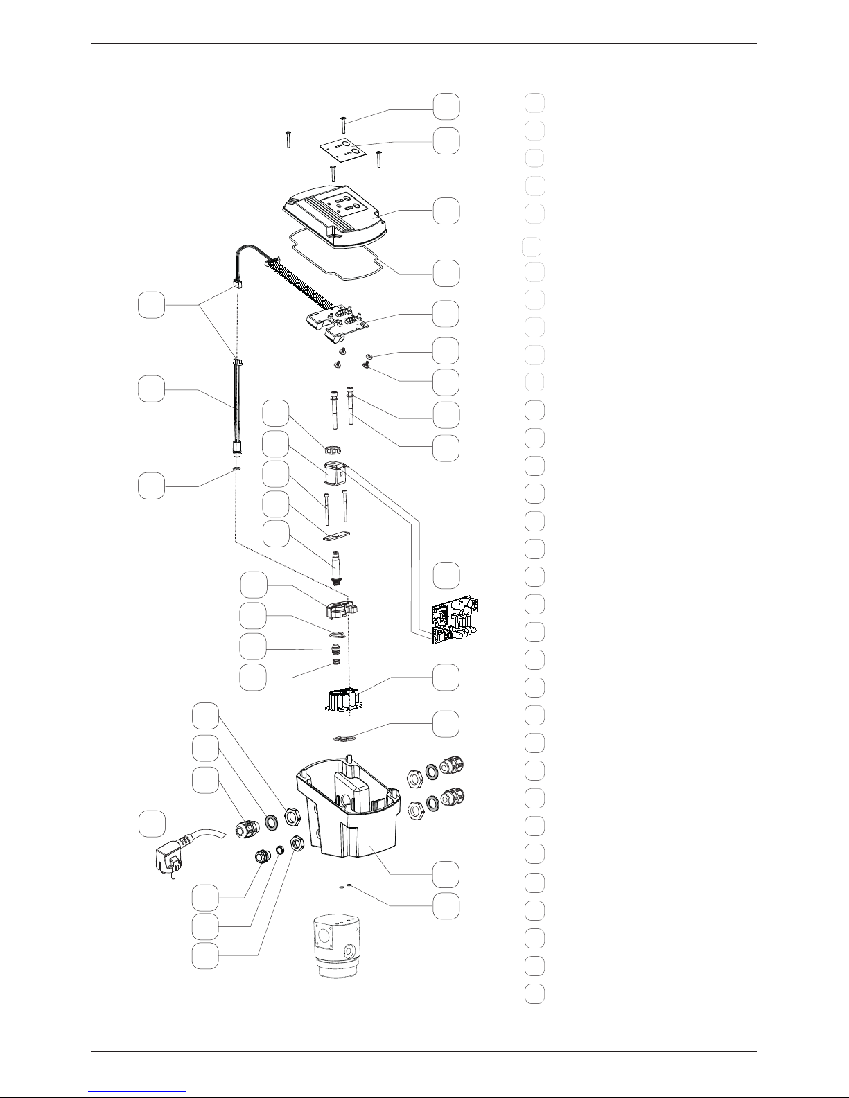
2.4. Parts and components
20
21
1
2
3
4
7
5
6
9
8
10
11
12
13
14
24
15
16
17
18
19
5a
27
26
29
25
32
28
30
31
23
22
1
Hood
2
Keyboard foil
3
Mushroom head bolt M3 x 20
4
Cord packing
5
Display printed circuit board with
plug connection
5a
Plug connection sensor
6
Countersunk head screw M3 x 8
7
Plastic washer
8
Screw M5 x 45
9
Washer 5.3
10
Knurled nut anchor system
11
Coil with cable150 mm
12
Screw M3 x 40
13
Retaining plate
14
Anchor system
15
Pilot valve seat
16
Seal pilot valve seat
17
Valve piston with seal
18
Pressure spring switch-over valve
19
Sensor with cable and plug connection
20
O-ring 8 x 1.5
21
Switch-over valve seat
22
Seal switch-over valve seat
23
Housing
24
Control board
25
Cable gland M16 x 1.5
26
Seal
27
Counter nut M16 x 1
28
Pressure compensation plug
29
Sleeve
30
Counter nut M12 x 1.5
31
O-ring 6 x 2
32
Power cable with plug
Installation and operation manual EN
12 DRYPOINT® M eco control
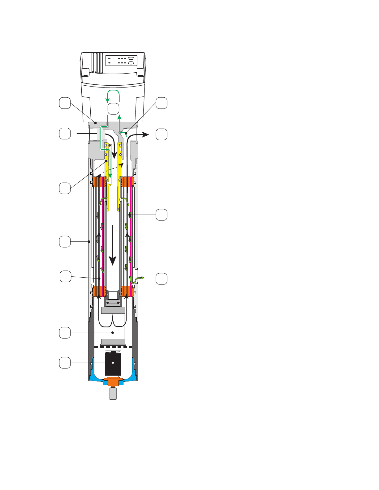
2.4.1. Principle function methods
1
2
4
3
6
7
9
8
11
10
12
5
Moist compressed air (2) enters the unit through the housing
head (1) and ows downwards through the core pipe of the
membrane element (5) into the housing (4). It then passes
through the nanolter (6) installed at the bottom outlet of
the core tube where all residual aerosols and particles are
removed from the compressed air. Separated condensate
ows out of the base and is routed through the oat drain-o
conduit (7).
The ow direction is reversed in the nanolter element area
and the damp compressed air ows through the membranes
of the internal membrane element.
A part of the compressed air ow
(9) is diverted downstream of the membrane element and
passed by the sensor continuously in the purge air control.
The sensor measuring results will be evaluated in the purge
air control and the purge air feed to the membrane dryer will
be opened as required. As a result, the purge air decreases to
atmospheric pressure and is considerably dryer as the damp
contained in the compressed air is distributed to a multiple of
the original volume.
The very dry purge air (10) is fed via the purge air duct in
the head and the purge air nozzle (3) on the external side of
the diaphragm (11) and evenly distributed by the arranged
position of the diaphragms. This means that two air ows
move through the membrane element in an opposite
direction with dierential damp content(5):
Damp compressed air on the inside and dry purge air on the
outside.
Due to the damp dierence, water diuses from the
compressed air into the purge air. The damp purge air (12) is
then released to the ambient air. The compressed air (8) exits
as dry from the membrane dryer.
EN Installation and operation manual
DRYPOINT® M eco control 13
The control software decides in dened cycles on the basis of the measurement results whether, and for how long, the
complete purge air volume must be supplied in order to achieve and stabilise the required degree of drying. This process
will be implemented via a targeted cycling of a solenoid valve. The duration for both subsequent described process steps
therefore varies in every cycle to retain the degree of drying within the specied tolerance range.
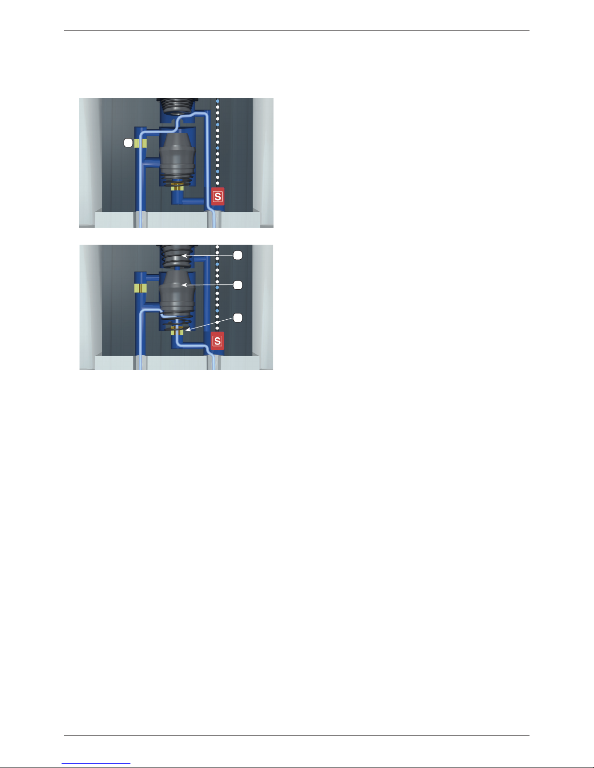
Function: Measuring gas ows
A very small partial ow of the dried compressed air
(measuring gas) ows continuously through the internal
duct guide past a temperature and damp sensor (S) to the
measuring gas jet (1). This sensor continuously species the
degree of drying for the compressed air in the measuring gas
and noties the result to the control system.
Function: Purge air ows
The control system continuously compares the measured
degree of drying of the measuring gas with the individual
specied set point value on the DRYPOINT® M eco control.
The valve unit will be actuated with deviations: The solenoid
core (2) and piston (3) close the valve seat so that the
compressed air ows through the purge air nozzle (4)
to the membrane dryer. The drying process commences
immediately.
2.4.2. Operating mode
Constant mode (-10 °C; factory-set as default) - Setting for a constant outlet pressure dew point:
The DRYPOINT® M eco control constantly retains the pressure dew point at the outlet between +10 and –26 °C in this
operating mode. If the set pressure dew point is <5K (kelvin) below the compressed-air temperature, then the set point
pressure dew point is reduced by one step (maximum. -26 °C). As soon as the minimum dierence of 5K is retained, then the
system returns to normal mode.
Dynamic mode - constant dierence between compressed air temperature and outlet pressure dew point:
In this operating mode, the pressure dew point is reduced relative to the compressed air temperature by a specied
dierence between 10 and 55 K. If the compressed air temperature alters, then the pressure dew point will automatically
follow suit. For programme-technical reasons, an increase in the compressed air temperature is limited to 2 °C/h in order to
reduce short-term alterations in the ambient conditions at the installation and/or assembly location.
1
3
2
4
Installation and operation manual EN
14 DRYPOINT® M eco control
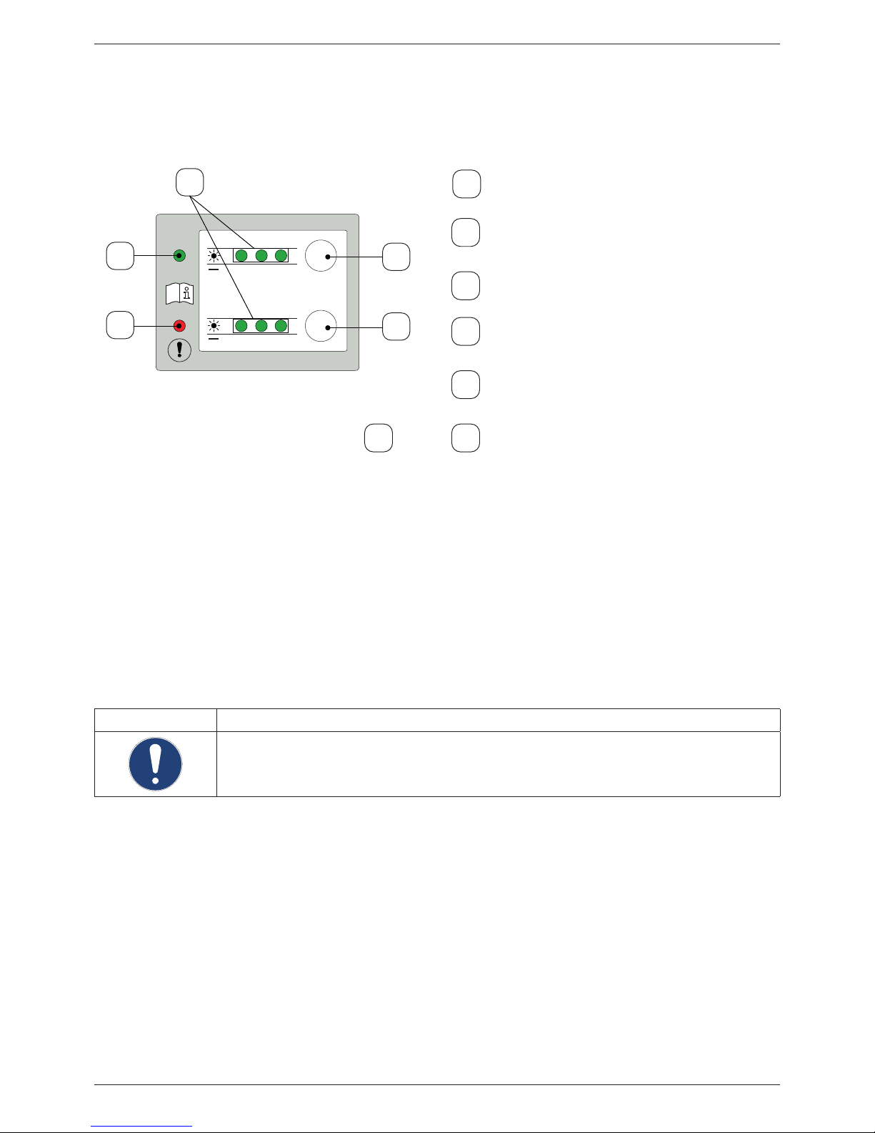
2.5. Control and display elements
The operation of the DRYPOINT® M eco control is executed via the user interface on the top of the housing. The current
operating status will be represented by LED indicators.
Test
Power
+1010+5200
30
Value
35 45 55
°C
°C
-5 -15 -26
Pressure
Dew
Point
∆
∆
...
...
4
5
1
3
2
1
Power LED (green)
Indicator for the operating mode and voltage
power supply
2
Warning LED (red)
Indicator for alarms, errors and malfunctions in
operation
3
Value LED (green)
Indicator for the set point values
4
>>Test<< button
Setting the operating mode or for testing the
solenoid valve function
5
>>Value<< button
Setting the degree of drying or activating the
service mode
4+5
Press and hold the >>Test<< + >>Value<< buttons
Unlock software → change settings
The pressure points on the >>Test<< and >>Value<< buttons are designed in such a way that inadvertent touching cannot
trigger operating functions. The software is programmed in such a way that a button must be pressed for a longer time
(approx. 0.2 second) to acquire a desired operating function.
If an operation function is initiated with a continuous pressing of the button(s), then the device will indicate the possible
commencement of the operation: All green value LEDs (3) ash. A time span of 10 seconds is then open for the action after
releasing the button(s). Every actuation of a button during this time span will result in the time span being available again
for the complete duration.
Once the action has been completed and no button has been pressed for 10 seconds, then the conrmation for nalising
the action will be executed via the control . All green value LEDs (3) ash.
The system then transfers into normal mode and will be controlled on the basis of the prescribed settings.
NOTE Additional information
For more information regarding the display and the test function of the solenoid valve, see “Operation” on
Page 26.

EN Installation and operation manual
DRYPOINT® M eco control 15
2.6. 4 ... 20 mA interface
The drying system is equipped with a 4 ... 20 mA interface via which the currently measured pressure dew point can be
issued (irrespective of operating mode).
4 mA ≙ -48 °C
20 mA ≙ +25 °C
Output value in case of error 24 mA
Increments: 0.5 °C
2.7. Alarm relay
The drying system is equipped with an alarm relay via which an error signal can be issued. There will not be a dierentiation
here between various types of errors.
Error list:
• Sensor errors (refer to device errors)
• Solenoid valve errors (refer to device errors)
• Exceeding the permissible deviation for degree of drying (Refer to 9.1.3)
• Failure of the voltage power supply (Refer to 9.1.1)
 Loading...