


Universal-Flap-Pocket-
Machine 100/58
Operating instructions
Version 2.1, 11-18-98
© 1998 – 1999 Beisler GmbH
Frohnradstr. 10 • D-63768 Hösbach • Phone-No. Service: +49-6021-501940 • Fax: +49-6021-540061
These operating instructions contain the following parts:
Part 1: Operating instructions (pages 1-xx)
adresses to the operator of the machine, that means the person who works at and with the machine
Part 2: Mechanics manual (pages 2-xx)
is used for the putting into operation, adjustment, troubleshooting and maintenance of the machine and adresses to qualified staff only
Part 3: Technical manual (pages 3-xx)
contains information on the further adjustment, maintenance, troubleshooting and repair of this machine and adresses to especially trained and experienced staff only.
Please obtain all safety, warning and other hints and regulations in this manual.

Part 1 Operating instructions
Hint
These operating instructions contain all information required for the operation of the machine. It adresses to the operator of the machine, that is the person that works at and with the machine. Please obtain all rules and regulations.
Contents |
Page |
|
Part 1 |
Operating instructions ...................................................................................... |
1-1 |
1 |
Security advice and warning hints ................................................................... |
1-2 |
1.1 |
Classification ........................................................................................................ |
1-2 |
1.2 |
Range of validity .................................................................................................. |
1-2 |
1.3 |
Authorized person ................................................................................................ |
1-2 |
1.4 |
General security advice and warning hints ........................................................... |
1-2 |
1.5 |
Copyright ............................................................................................................. |
1-3 |
2 |
Preliminary remarks .......................................................................................... |
1-4 |
2.1 |
Introduction .......................................................................................................... |
1-4 |
2.2 |
Limitation of liability .............................................................................................. |
1-4 |
2.3 |
Guarantee regulations ......................................................................................... |
1-5 |
2.4 |
Use as agreed ..................................................................................................... |
1-5 |
2.5 |
Description of the machine .................................................................................. |
1-5 |
2.6 |
Main parts of the machine .................................................................................... |
1-6 |
3 |
Security............................................................................................................... |
1-7 |
3.1 |
Available security systems ................................................................................... |
1-7 |
3.1.1 |
Program stop button ............................................................................................ |
1-7 |
3.1.2 |
Mains /emergency stop button ............................................................................. |
1-8 |
3.2 |
Security measures of the operator ....................................................................... |
1-8 |
4 |
Operation of the machine .................................................................................. |
1-9 |
4.1 |
Controls and indicators ........................................................................................ |
1-9 |
4.1.1 |
Operation device ................................................................................................ |
1-10 |
4.1.2 |
Insertion station.................................................................................................. |
1-13 |
4.1.3 |
Mains / emergency stop button .......................................................................... |
1-13 |
4.1.4 |
Foot pedal machine sequence ........................................................................... |
1-13 |
4.1.5 |
Foot pedal vacuum ............................................................................................ |
1-13 |
4.1.6 |
Foot pedal stacker ............................................................................................. |
1-13 |
4.1.7 |
Swing out the folder ........................................................................................... |
1-14 |
4.1.8 |
Change folder .................................................................................................... |
1-14 |
4.1.9 |
Change interface roll .......................................................................................... |
1-15 |
4.1.10 |
Empty the stacker .............................................................................................. |
1-16 |
4.2 |
Operation ........................................................................................................... |
1-16 |
4.2.1 |
Machine sequence ............................................................................................. |
1-16 |
4.2.2 |
Program operation ............................................................................................. |
1-16 |
4.2.3 |
Select a sewing program.................................................................................... |
1-16 |
4.2.4 |
Enable/disable seams ........................................................................................ |
1-17 |
4.2.5 |
Change seam length .......................................................................................... |
1-17 |
4.2.6 |
Remove and add seams .................................................................................... |
1-17 |
5 |
Required cleanings .......................................................................................... |
1-18 |
1-1

1 |
Security advice and warning hints |
1.1Classification
Three different types of hints are used in this manual, which are indicated with different symbols and signalling words:
DANGER
This indicates a possibly dangerous situation or action, which may cause injuries to persons or severe damage to the machine.
ATTENTION
This indicates a situation or action, which may cause damage to the machine.
Hint
This indicates hints for a better use and other helpful information or hints.
Please obey all rules and regulations.
1.2Range of validity
This operating manual is valid for Pocket-Piping-Automatons manufactured by Beisler named ‘Universal-Pocket-Piping-Automaton 100/58’.
This operating manual is not valid for the sewing head applied in the machine. Please refer to the operating manual of the sewing head delivered with the machine, for which we don’t take any liability.
Further security advice (verbal and written) for this machine or the components will not be repealed by this manual.
1.3Authorized person
Danger
Danger might arise for persons, things and environment by inappropriate operation of this machine. Installation and maintenance duties may only be carried out by authorized staff.
Persons are regarded as authorized, who are able to recognize possible danger and judge the assigned duties from their technical education and experience.
1.4General security advice and warning hints
Danger
Danger might arise for persons, things and environment by inappropriate operation of this machine. Installation and maintenance duties may only be carried out by authorized staff.
1-2

Danger
Danger of injuries in the range of the sewing head! Don’t grasp into the affected area of the needle during the sewing process!
Danger
Before any operations at or with the machine (putting into operation, operation, maintenance, repair, etc.) the person carrying out has to read and understand this manual with each appendix completely.
Danger
Before carrying out maintenance or repair duties, the mains supply must be cut off. Additionally pressure must be released from the pneu-matical system.
Attention
The machine will be destroyed by a connection to a wrong mains voltage! See the section ‘Technical data’ before connecting the power supply.
1.5Copyright
© 1997 Beisler GmbH, Hösbach
Pocket-Piping-Automaton
The Universal-Pocket-Piping-Automaton 100/58 and this operating manual with all parts are protected on copyright. Manufacture without license will be prosecuted by law. All rights reserved on this operating manual, including reproduction in any thinkable way, either by copying, printing, on any data recording media or in translated form. Reproduction of this operating manual - even in extracts - only with written approval by Beisler GmbH.
This operating manual contains a description of the product, but no promise of certain qualities or results of use. The operating manual has been proved before delivery. The Beisler GmbH takes the liability, that this operating manual if free of errors reducing its value for the estimated use. The editors don’t take liability for consecuting damage arising through application of the operating manual. We are always thankful for hints and ideas.
The technical standard of the common delivery of product and operating manual by the Beisler GmbH is decisive, if not other information is given. Technical changes without prior notice are reserved, previous operating manuals loose validity.
The general conditions of sales and delivery of the Beisler GmbH are valid.
Do you have questions or problems with installation or putting into operation? Don’t hesitate to call us.
Beisler GmbH
Frohnradstr. 10 - D-63768 Hösbach Tel: (+49) 6021 / 50 19 0
Fax: (+49) 6021 / 50 19 10
1-3
2 |
Preliminary remarks |
2.1Introduction
This operating manual adresses to the operator of the machine, that is the person that works with the machine. It is not a technical manual. Please ask questions exceeding the contents of this operating manual to our service staff.
Attention
All service and maintenance duties at this Pocket-Piping-Automaton may only be carried out by qualified staff (qualified electrical employee or electrotechnical instructed person according to IEC 364 and DIN EN 60204-1). Machine operation may only be carried out by an instructed person, who had read and understood this operating manual completely.
Attention
Any structural changes to the machine, either electrically, mechanically or regarding the machine control, are suspect to the responsibility of the machine owner.
The following documents are part of the documentation of the Universal-
Pocket-Piping-Automaton 100/58:
1.Electrical wiring plans
2.Parts list
Please check the documents delivered with the machine for completeness.
2.2Limitation of liability
We guarantee the faultless functioning of our product in accordance with our advertising, the product informations edited by the Beisler GmbH and this manual. Further product-features are not guaranteed. We take no liability for the economy and faultless function if the product is used for a different purpose then that described in the chapter „Use as agreed“.
Compensation claims are generally impossible, except if intention or culpable negligence by the Beisler GmbH is proved, or if assured productfeatures are not provided. If this machine is used in environments, for which it is not suited or which do not represent the technical standard, we are not responsible for the consequences.
We don’t accept responsibility for damages at installations and systems in the surroundings of this machine, which are caused by a fault of the product or an error in this manual.
We are not responsible for the violation of patents and/or other rights of third persons outside the Federal Republic of Germany.
We are not liable for damages, which result from improper operations according to this manual. We are not liable for missed profit and for consecuting damages due to non-regardance of security advices and warning hints. We don’t accept liability for damages which resulted from the use of tools and accessoires which are not delivered and/or approved by the Beisler GmbH.
The prdocuts of the Beisler GmbH are designed for a long life. They represent the standard of technique and science and were checked on all functions individually before delivery. The electrical construction corresponds to the current norms and regulations, particularly DIN 5713 / VDE 0113. Beisler GmbH is doing product and market research for the further
1-4

development and permanent improvement of their products. In the case of faults and/or technical trouble please contact the Beisler GmbH service staff. We assure that suitable measures will be done immediately.
The Beisler GmbH guarantee regualtions are valid, which we will send to you on demand.
2.3Guarantee regulations
We guarantee the fault-free functioning of the Universal-Pocket-Piping- Automaton 100/58 according to this operating manual except the tools for a time range of six months after delivery. If the machine is used in doubleor triple-shift operation, the term of guarantee is reduced to three or two months.
The term of guarantee starts with the date of delivery to the customer, independant from the time of putting into operation. Guarantee will be spoiled, if the machine isn’t installed and operated according to this operating manual and the regulations given by the Beisler GmbH staff. A cost-free repair is only possible, if all regulations considering storage, transportation and putting into operations have been obeyed.
Customers and third persons may only mesh with the machine after getting a written approval by the Beisler GmbH. The Beisler GmbH takes no responsibility for injuries and damages arising from non-obeyance of this stipulation. All warranty will be spoiled in this case.
The Beisler GmbH takes no responsibility for faults of the machine as consequence of defective or functional faulty equipment in the surrounding of the machine or by the use of accessoires, which were not delivered by the Beisler GmbH.
The general conditions of sale and delivery of the Beisler GmbH are valid.
2.4Use as agreed
The Universal-Pocket-Piping-Automaton 100/58 has been developed for the piping of pockets and the sewing in of pocket bags.
Danger
This machine has been developed and build for a certain purpose. Adaptions may influence security equipments negatively. We recommend to contact our service staff in such a case.
2.5Description of the machine
The Universal-Pocket-Piping-Automaton 100/58 allows the automatic piping of pockets. The machine is equipped with a cutting device, a clamp transportation system, a sewing head and a stacking system for the produced pieces.
All components of the machine are mounted on a base frame made of square steel pipes and controlled by an innovative micro-processor system.
Machine operation is achieved with an operation device. Here you can open several control programs, define new programs and check all machine components individually for maintenance and repair duties.
1-5
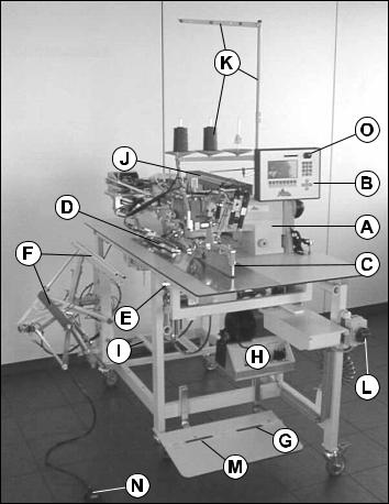
2.6Main parts of the machine
ASewing head
BOperation device
CInsertion station
DClamp transportation
EMitre knife
FStacker
GFoot pedal sew sequence
HSew motor
IPower / air supply
JPower distribution
KSpool rack
LMains / emergency stop switch
MFoot pedal vacuum
NFoot pedal stacker
OProgram stop button
The following chapters contain further information on the machine’s components.
1-6
3 Security
The topic of this chapter is the security exclusively. Please see chapter 1 for the general security advice and warning hints and the security and warning hints in the other chapters of this operating manual.
3.1Available security systems
Danger
Check all security systems daily for functioning and effectivity!
Danger
Changes to the machine may influence function and effectivity of the security systems negatively!
AProgram stop button
BMains / emergency stop button
3.1.1Program stop button
The program stop button is mounted in the right upper corner of the operation device. After pressing, all movements and the sewing process will be stopped immediately.
Before a re-start the program stop button must be turned to the right to be unlocked. With the release, the reset will be triggered.
1-7
3.1.2Mains /emergency stop button
The mains / emergency stop switch is mounted on the front side of the machine, right-handed below the working plate. It can be used to cut-off the power supply.
3.2Security measures of the operator
The security systems of this machine work passively, that means that they can only react on certain incidents. To achieve the required security for your health and that of your collegues, active measures of the operator are required.
Please obey the following general rules for the use of this machine:
1.Always work concetrated and avoid actions with a risk.
2.Don’t try to bridge existing security systems or to disable them in any way.
3.Check all security systems on function and effectivity before starting work.
4.Cut off the power supply before opening the switchbox.
5.Switch off the machine with the mains / emergency stop switch, before executing cleaning and mainetenance duties.
1-8
4 |
Operation of the machine |
Danger
This machine may only be operated by qualified staff, who had read and understood this operating manual completely.
4.1Controls and indicators
AOperation device
BInsertion station
CMains / emergency stop button
DFoot pedal machine sequence
EFoot pedal vacuum
FFoot pedal stacker
1-9
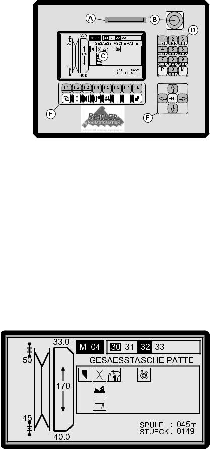
4.1.1Operation device
During production the machine can be operated with the operating device; existing programs can be called and new programmed. You will find the program stop button at the device.
ASlot for the Memory card
BProgram stop button
CDisplay
DTen key pad with P- and M-key
EFunction keys
FArrow and enter keys
The elements of the operating devices have the following occupations:
4.1.1.1Slot for the Memory card
The Memory card is used as a backup memory for software and programs of the machine. You can load programs to the Memory card or read them after a possible data loss into the machine.
4.1.1.2Program stop button
By pressing the program stop button, all movements of the machine will be stopped immediately. To continue production, you have to turn the button to the right and release it.
4.1.1.3Display
1-10

All information required for the operation of the machine will be imaged in the display. During normal production the display shows the following (see Pict. 6):
•the graphic on the left side images the mitre cut of the pocket; in the shown example, the mitre cutter cuts the basic value 50 at the seam start and 0.5 mm less at the end, that is the value 45
•the graphic to the right shows the seam or flap lenght of the pocket; the value displayed above the flap (33.0) defines, how far the flap will be pushed behind the needle, after the photocell has recognized the flap (value for the seam start); the value displayed below the flap (40.0) defines, how long the machine continues sewing, after the photocell has recognized the end of the flap
•the most upper line shows the number of the selected program (M01) and the seams assigned to this program (30, 31, 32 and 33); seams 30 and 32 are enabled (32 will be the next seam to be sewed), 31 and 33 are disabled
•the name of the current seam is displayed to the right
•the square below contains the icons of the machine functions assigned to the current seam
•below the square, the stock of bobbin thread (45 m) and the number of produced parts (149) are displayed
4.1.1.4Ten key pad with P- and M-key
Numerical inputs can be done using the ten key pad.
The letters displayed below the digits can be entered, after the function key with the corresponding color indication has been pressed before.
The P-key is used in several steps of the machine programming. Sewing programs can be selected after pressing the M-key.
4.1.1.5Function keys – lower occupation
The function keys are occupied as follows
switches to the upper occupation of the function keys
Mitre knife correction; press this key once to change the mitre knife position at the seam start; press F1 and the cursor stands on the seam start; press twice to change the position at the seam end; after pressing F1, enter the new value using the ten key pad, which will be displayed in the left-handed graphic; 50 = middle value; the higher the value, the more far the mitre knife cuts to the outside
e.g. old value 50, new value 56 and the mitre knife cuts 0.6 mm more to the outside
e.g. old value 50, new value 22, the mitre knife cuts 2.8 mm more to the inside
1-11
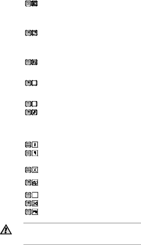
Change pocket length; press F3 and enter the new value for the length to be sewed; when producing with flap, this sets the photo cell security length, too; e.g. security length 140 mm allows the sewing of a flap length between 130 and 150 mm; when producing flaps it is possible to disable the security length by entering 999 here.
Sewing-over at seam start and end (only valid when sewing with flap); press once to set the sewing-over at seam start, twice to set it at seam end; enter the new value using the ten key pad Seam start: the smaller the set value, the more the flap will be sewed over; seam end: the bigger the set value, the more the flap will be sewed over
Pick needle thread manually; after the first pressing, the main clamp drives to end position, with the second pressing the
needle thread catcher will be enabled; it remains enabled, until the key is released
Push interface forward manually (option); after changing the interface roll, the interface will be cut with a key pressure and then be pushed in position (only available if interface mode is enabled)
reserved
Reset key; use this key to reset the program sequence step by step; sets the clamp into starting position
4.1.1.6Function keys – upper occupation
The function keys are double occupied. Press F1 to switch to the upper key occupation. The icons will be displayed in the lower line.
switches back to the lower key occupation
Switch middle knife on/off; the knife is switched off, until it will be switched on here; together with the middle knife, the mitre knife is switched off
Switch mitre knife on/off; it remains switched off, until it will be switched on here
Switch stacker on/off; it remains switched off until it will be switched on here
Here without function
Sets counter to zero
Manual spooling; the sewing head runs with low revs, after a second key press, it stops in the upper needle position
Attention
At machines with insertion station, the station must be swung out first (see chapter 4.1.6); in any case, both threads must be removed from the needles and the spools from the pickers.
1-12
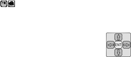
Reset spool thread length; when removing a half-full and inserting a full spool, you can display the whole thread length by pressing this key
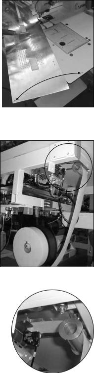
4.1.1.7Arrow and Enter-keys
Use the arrow keys to move the flashing cursor between the different sections of a display. Confirm inputs using the Enter key.
4.1.2Insertion station
The parts to be manufactured are inserted at the insertion station. Use the marking lamps to align the parts exactly.
4.1.3Mains / emergency stop button
With the mains / emergency stop button, you can cut-off the power supply of the machine.
4.1.4Foot pedal machine sequence
Use this foot pedal to trigger the steps of the machine sequence (see further below).
4.1.5Foot pedal vacuum
Press this foot pedal to enable the vacuum. The parts inserted at the insertion station are fixed by the vacuum which will be disabled automatically, after the main clamp has picked up the parts.
4.1.6Foot pedal stacker
Press the foot pedal stacker to open the stacker to be able to take out the stacked parts.
1-13

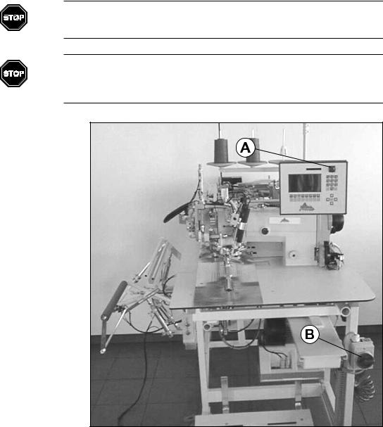
4.1.7Swing out the folder
For several reasons (e.g. manual spooling), the folder must be swung out to get access to the sewing head. Pull out the locking pin (A) and swing the folder (B) to the left.
When swinging back, move the folder slowly to the right until the locking pin inserts feelable.
Attention
The folder and the lamps of the crosshair attached to it are adjusted exactly and are sensitive against violence. Therefore, swing the folder slowly and without the use of power.
4.1.8Change folder
1-14
Different folders are needed for different pocket shapes (e.g. double/single piping):
1.Open the locking (B) of the folder (A).
2.Pull the folder towards yourself and downwards to remove it.
3.Push in the new folder from the bottom side into the two attachments and then push it forward.
4.Fix the locking (B).
4.1.9Change interface roll
The interface roll is placed below the working plate and can be changed this way:
1.Lift the insertion plate at the front side and push it to the left.
2.Remove all rests of the interface in the machine.
3.Insert the new interface roll.
4. Insert the interface over the roll into the interface guiding.
1-15
5.Press F6 repeatedly, until the interface appears above the working plate.
6.Mount the insertion plate; be sure that the positioning pins are inserted into the drill holes.
4.1.10Empty the stacker
Press the foot pedal of the stacker, if it is full. The stacker will open and you can remove the parts. Release the foot pedal to close the stacker.
4.2Operation
4.2.1Machine sequence
The production sequence is divided into several parts:
1.Machine sequence can start, if the machine is in starting position.
2.Insert the parts to be sewed and align them exactly.
3.Press the foot pedal machine sequence and the clamp comes forward.
4.Press the foot pedal again, the clamp will be lowered.
5.Press foot pedal, the folder is lowered and the fold pushers are driven to the front.
6.Press foot pedal, the flap clamp closes.
7.Press foot pedal, the clamp pushes the part under the sewing head, it will be sewed there, the mitres will be cut, the clamp opens and the sewed part will be stacked.
The operator can trigger each step with a short pressing of the foot pedal, or run an automatic process by keeping the foot pedal pressed.
Depending on the programming, different machine sequences might occur.
4.2.2Program operation
The machine is operated with programs, which can be selected by the operator. A program is stored at a memory location (e.g. ‘M01’) and contains one or several seams (max. number is six).
The selected program and the assigned seams are imaged in the upper line of the display. The machine executes all enabled seams of a program sequentially. An enabled seam is displayed inverted (white on black).
You can produce several pocket shapes and lengths sequentially, without changing the sewing program. This allows to sew several pockets of a jacket part.
The following operational actions are explained in this chapter:
•select a sewing program
•enable/disable seams
•change seam lengths
•change sewing programs
•create new sewing programs
•program new seams
4.2.3Select a sewing program
The current sewing program is displayed in the upper line of the display. How to select a program:
1. Press M-key.
2. Enter the number of the desired program using the ten key pad. 3. Press ENT-key.
1-16
4.2.4Enable/disable seams
Seams are assigned to every sewing program. All enabled seams are sewed sequentially. Enabled seams are displayed inverted (white on black).
If a seams shall be skipped, it must be disabled. How to enable/disable a seam:
1.Move the cursor on the desired seam using the arrow keys.
2.Press the ENT-key to enable/disable the seam.
4.2.5Change seam length
Several parameters of the current seam are imaged in the left half of the display (e.g. seam length, mitre knife position). You can change these settings individually using the function keys.
All changes executed with the function keys are stored for all seams with the same number, even if they are used in different programs.
Further information are contained in the chapter ‘4.1.1.5 Function keys’.
4.2.6Remove and add seams
You can add seams to and remove them from sewing programs:
4.2.6.1Remove seams
1.Select the sewing program to be changed.
2.Press the P-key.
3.Press F1.
4.Move the cursor on the seam to be removed using the arrow keys.
5.Press the M-key.
6.Repeat steps 4. and 5. for all seams to be removed.
4.2.6.2Add seams
1.Select the sewing program to be changed.
2.Press the P-key.
3.Press F1.
4.Use the arrow keys to move the cursor to the place, where you want to add a seam.
5.Press the ENT-key.
6.Enter the number of the desired seam.
7.Repeat steps 4. to 6. for all seams to be added to the current sewing program.
8.Press the P-key to store the settings and leave the submenu.
1-17
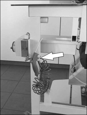
5 Required cleanings
To achieve the value and function of the machine, we recommend to keep it always clean and free of spare materials and waste.
Blow off threats and cloth rests daily from the machine using the air pistol.Below the air pistol you see a supply bottle for the oil needed in the sewing head.
1-18
Part 2 Mechanics manual
Hint
This part of the operating instructions contains all information required to put the machine into operation and to do programming, troubleshooting and maintenance. It adresses to trained technical personnel, which is able to overview their tasks and recognize possible danger at an early moment. The operating instructions given in part 1 of this manual are to be considered as part of this mechanics manual.
Contents |
Page |
|
Part 2 |
Mechanics manual ............................................................................................. |
2-1 |
1 |
Delivery, transportation, storage ...................................................................... |
2-2 |
1.1 |
Delivery ................................................................................................................ |
2-2 |
1.2 |
Transportation ...................................................................................................... |
2-2 |
1.3 |
Storage ................................................................................................................ |
2-2 |
2 |
Installation .......................................................................................................... |
2-3 |
2.1 |
Technical data ...................................................................................................... |
2-3 |
2.2 |
Mechanical installation ......................................................................................... |
2-3 |
2.2.1 |
Unpack and put up ............................................................................................... |
2-3 |
2.2.2 |
Connection of air supply....................................................................................... |
2-4 |
2.3 |
Elektrical installation ............................................................................................ |
2-4 |
2.4 |
First putting into operation .................................................................................... |
2-5 |
3 |
Programming instructions ................................................................................ |
2-6 |
3.1 |
Create new sewing programs .............................................................................. |
2-6 |
3.1.1 |
Select a M-memory location ................................................................................. |
2-6 |
3.1.2 |
Add seams ........................................................................................................... |
2-6 |
3.1.3 |
Copy seams ......................................................................................................... |
2-6 |
3.1.4 |
Adjust seams ....................................................................................................... |
2-6 |
3.1.5 |
Name seams........................................................................................................ |
2-7 |
3.1.6 |
Delete seams ....................................................................................................... |
2-7 |
3.2 |
Seam functions .................................................................................................... |
2-7 |
3.3 |
Seam parameters ................................................................................................ |
2-9 |
3.3.1 |
Seam parameter 30: Flap clamp mode ............................................................... |
2-11 |
3.3.2 |
Working WITHOUT automatic clamp push-back................................................ |
2-13 |
3.3.3 |
Working WITH automatic clamp push back ....................................................... |
2-13 |
3.3.4 |
Working with INTERMEDIATE STOP of the main clamp.................................... |
2-13 |
3.3.5 |
Working with automatic PICK UP PART using the main clamp .......................... |
2-13 |
3.4 |
Seam images ..................................................................................................... |
2-14 |
3.4.1 |
Sewing with catch .............................................................................................. |
2-14 |
3.4.2 |
Sewing with stitch condensation ........................................................................ |
2-14 |
3.4.3 |
Sewing with stowing ........................................................................................... |
2-14 |
3.5 |
Basic parameters ............................................................................................... |
2-15 |
4 |
Troubleshooting hints ..................................................................................... |
2-18 |
5 |
Maintenance of the machine ........................................................................... |
2-21 |
5.1 |
Water separator at air connector........................................................................ |
2-21 |
5.2 |
Grease linear guiding ......................................................................................... |
2-21 |
5.3 |
Use of the Memory Card .................................................................................... |
2-22 |
5.3.1 |
Saving seam data on the Memory Card ............................................................. |
2-22 |
5.3.2 |
Loading seam data from the Memory Card ........................................................ |
2-22 |
5.4 |
Loading data from the EPROMs ........................................................................ |
2-23 |
5.4.1 |
Loading the basic parameters ............................................................................ |
2-23 |
5.4.2 |
Loading seam parameters ................................................................................. |
2-23 |
5.5 |
Test programs and diagnostics .......................................................................... |
2-23 |
5.5.1 |
I/O-Test .............................................................................................................. |
2-23 |
5.5.2 |
Diagnostics ........................................................................................................ |
2-26 |
5.5.3 |
Service Code ..................................................................................................... |
2-28 |
5.6 |
Preset sewing programs .................................................................................... |
2-29 |
5.7 |
Diagram of the menu structure .......................................................................... |
2-30 |
|
|
2-1 |

1 |
Delivery, transportation, storage |
1.1Delivery
Hint
Check right after receiving the machine, whether all parts according to the parts list are complete and without damage. Later claims can’t be accepted.
If you see damage to the transportation packing of the machine, which indicates a possible damage to the delivered parts, don’t hesitate to claim this to the transportation company.
1.2Transportation
Generally it is possible to move the machine. Obey the following hints:
1.Cut off the power supply, release the pneumatical pressure.
2.Fix movable and loose parts.
3.Lift the base with a hoisting device and be sure to lift possible additional devices (e.g. stacker). If the machine is equipped with transportation casters (option), you will have to release the brakes at every caster.
4.Move the machine carefully to the new location.
Attention
Attention when moving the machine on sloping areas! Enormous pull power arises from the machine weight.
1.3Storage
If no other agreement is fixed, the following limitations have to be kept:
1.In closed rooms only.
2.Temperature range -10 ... +45 °C.
3.Humidity max. 80% non-condensing.
Attention
If stored or transported in improper environments, the machine can be damaged severely. Damages may not be visible from the outside.
2-2

2 Installation
Attention
Installation and putting into operation may only be carried out by mechanically and electrically qualified staff. These people must read and understand the complete operating manual before starting.
2.1Technical data
Dimensions |
1.600 x 750 x 1.300mm (LxWxH) |
|
Table height |
830 mm |
|
Weight |
220 kg |
|
Mains power |
220 V AC |
|
Power consumption |
0,7 kW |
|
Fuse |
10 A |
|
Req. air pressure 6 bar |
|
|
Req. air quality |
oil-free |
|
Air consumption |
5 NL/WD |
|
2.2Mechanical installation
Attention
Check before starting the installation, whether the desired location meets the requirements (see chapter 2.1, technical data). This is very important regarding the stability of the ground.
2.2.1Unpack and put up
1.Remove the packing material and possible transportation protections.
2.Position the machine on a solid and horizontal ground.
3.Level the machine to a horizontal stand using the adjustable frame feet.
2-3
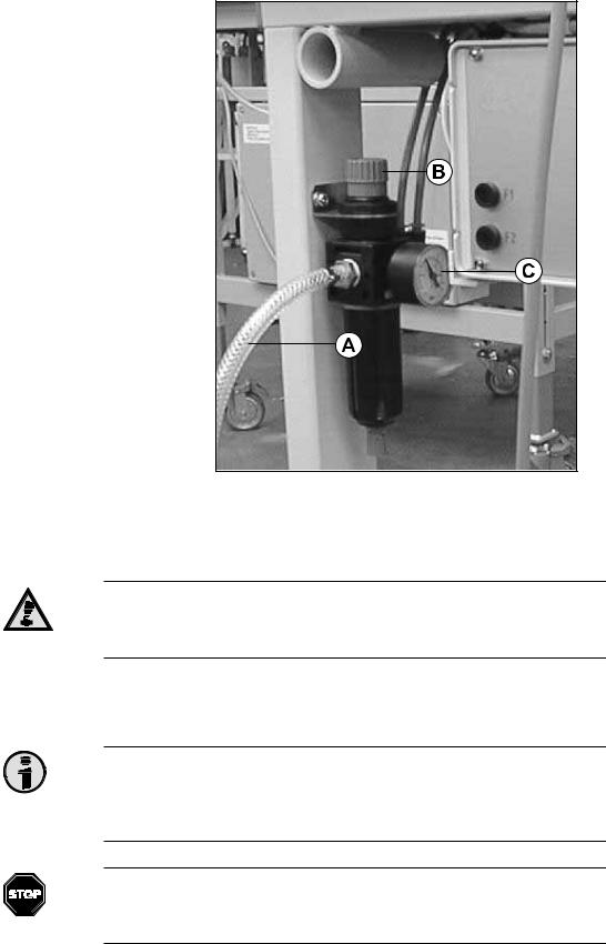
2.2.2Connection of air supply
1.Connect the air pipe (A) to your air system.
2.Open the air supply of your air system.
3.Level the air pressure to 6 bar using the control (B); the air pressure can be read at the scale (C).
Attention
We recommend to switch off the air supply when the machine is not in duty. Use the black control (B).
2.3Elektrical installation
Hint
All work at the electrical components of the machine may only be carried by qualified staff (qualified electrical employee or instructed person according to IEC 364 and DIN EN 60204-1).
Danger
Parts under electrical current! Without cutting off the power supply, you might be injured severely. Please obey the security advice given in chapter 1.
2-4
 Loading...