


100/68
100/68
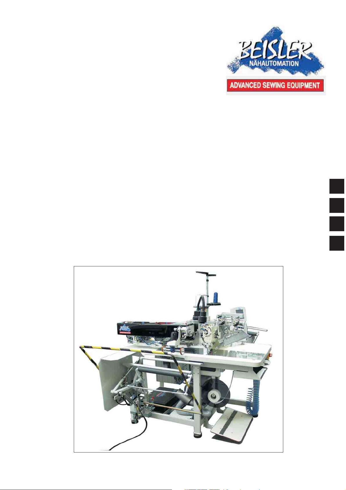
Universal
Piped-Pocket-Sewing unit
Operating instructions
Assembly instructions
Service instructions
Programming instructions
1
2
3
4
Ausgabe / Edition: 02/2007 Printed in Federal Republic of Germany Teile-Nr.:/Part-No.:


Foreword
This instruction manual is intended to help the user to become familiar
with the machine and take advantage of its application possibilities in
accordance with the recommendations.
The instruction manual contains important information on how to
operate the machine securely, properly and economically. Observation
of the instructions eliminates danger, reduces costs for repair and
down-times, and increases the reliability and ute of the machine.
The instruction manual is intended to complement existing national
accident prevention and environment protection regulations.
The instruction manual must always be available at the
machine/sewing unit.
The instruction manual must be read and applied by any person that is
authorized to work on the machine/sewing unit. This means:
Operation, including equipping, troubleshooting during the work cycle,
removing of fabric waste,
–
Service (maintenance, inspection, repair) and/or
–
Transport.
The user also has to assure that only authorized personnel work on the
machine.
The user is obliged to check the machine at least once per shift for
apparent damages and to immediatly report any changes (including the
performance in service), which impair the safety.
The user company must ensure that the machine is only operated in
perfect working order.
Never remove or disable any safety devices.
If safety devices need to be removed for equipping, repairing or
maintaining, the safety devices must be remounted directly after
completion of the maintenance and repair work.
Unauthorized modification of the machine rules out liability of the
manufacturer for damage resulting from this.
Observe all safety and danger recommendations on the machine/unit!
The yellow-and-black striped surfaces designate permanend danger
areas, eg danger of squashing, cutting, shearing or collision.
Besides the recommendations in this instruction manual also observe
the general safety and accident prevention regulations!

General safety instructions
The non-observance ot the following satety instructions can
cause bodily injuries or damages to the machine.
1. The machine must only be commissioned in full knowledge of the
2. Before putting into service also read the safety rules and
3. The machine must be used only for the purpose intended. Use of
4. When gauge parts are exchanged (e.g. needle, presser foot,
instruction book and operated by persons with appropriate
training.
instructions of the motor supplier.
the machine without the safety devices is not permitted. Observe
all the relevant safety regulations.
needle plate, feed dog and bobbin) when threading, when the
workplace is left, and during service work, the machine must be
disconnected from the mains by switching off the master switch or
disconnecting the mains plug.
5. Daily servicing work must be carried out only by appropriately
trained persons.
6. Repairs, conversion and special maintenance work must only be
carried out by technicians or persons with appropriate training.
7. For service or repair work on pneumatic systems, disconnect the
machine from the compressed air supply system (max. 7-10 bar).
Before disconnecting, reduce the pressure of the maintenance
unit.
Exceptions to this are only adjustments and functions checks
made by appropriately trained technicians.
8. Work on the electrical equipment must be carried out only by
electricians or appropriately trained persons.
9. Work on parts and systems under electric current is not permitted,
except as specified in regulations DIN VDE 0105.
10. Conversion or changes to the machine must be authorized by us
and made only in adherence to all safety regulations.
11. For repairs, only replacement parts approved by us must be used.
12. Commissioning of the sewing head is prohibited until such time as
the entire sewing unit is found to comply with EC directives.
It is absolutely necessary to to respect
the safety instructions marked by these signs.
Danger of bodily injuries !
Please note also the general safty instructions.

Index Page:
Part 1: Operating instructions 100/68
1. Description of product ..............................................5
1.1 Description of proper use .............................................5
1.2 Brief description...................................................5
1.3 Technical data ....................................................6
2. Operating ......................................................7
2.1 Swivelling the folding station aside .......................................7
2.2 Removing the fabric sliding sheet ........................................8
2.3 Needles and threads ................................................9
2.4 Threading the needle thread ...........................................11
2.5 Winding up the hook thread ...........................................12
2.6 Remaining thread monitor ............................................13
2.7 Slanted pocket opening (optional) .......................................14
2.7.1 Swivelling the corner knife station in and out .................................14
1
3. Switching on - Starting the sewing process - Program stop - Switching off ...........16
3.1 Switching on ....................................................16
3.2 Reference position ................................................17
3.3 Starting the sewing process ...........................................17
3.4 Program stop....................................................18
3.5 Switching off ....................................................18
4. Working methods ................................................19
4.1 Working method “Production of trousers” ...................................20
5. Quick clamp adjustment and folder monitoring .............................22
6. Function and operation of the optional equipment ...........................23
6.1 Tape feeding unit with automatic trimming and tape monitor........................23
6.2 Endless zipper device ..............................................26
7. Maintenance....................................................27
7.1 Cleaning ......................................................27
7.2 Oil level control ..................................................28


1. Description of product
1.1 Description of proper use
The Beisler 100/68 is a sewing unit which can properly be used for
sewing light to medium-weight material. Such material is, as a rule,
made of textile fibres or leather. These materials are used in the
garment industry.
In general only dry material must be sewn on this machine. The
material must not contain any hard objects.
The seam is generally made with core thread, polyester fibre
or cotton threads.
The dimensions for needle and hook threads can be taken from the
table in chapter 2.4.
Before using any other threads it is necessary to estimate the
consequential dangers and to take the respective safety measures, if
required.
This sewing unit must only be installed and operated in dry and
well-kept rooms. If the sewing unit is used in other rooms, which are
not dry and well-kept, further measures to be agreed upon may
become necessary (see EN 60204-31 : 1999).
We, as manufacturer of industrial sewing machines, assume that at
least semi-skilled operating personnel will be working on our products
so that all usual operations and, where applicable, their risks are
presumed to be known.
1
1.2 Brief description
The Beisler 100/68 is a sewing unit for automated runstitching of piped
pocket, flap pocket and welt pocket openings with rectangular or
slanted pocket corners.
The slanted pocket corners result from the offset of the two seam rows.
It is possible to sew different slants at the seam beginning and at the
seam end.
Depending on the working method various feeding devices, corner
knife stations and optional equipment are used.
Machine head
–
Twin needle lockstitch version
–
Needle bars can be switched/engaged jointly or separately
–
Vertical hook
–
Externally driven centre knife, speed and release time/switching
time programmable
–
Thread trimming device for needle and hook threads
–
Monitor for the needle threads
–
Photoelectric remaining thread monitor for the hook threads
–
DC direct sewing drive
Step motors for the material feed and the length adjustment of the
corner trimming device
The step motor technology allows short machine times and guarantees
an absolutely precise material feed and accurate corner incisions.
5

Thus, it contributes to a pocket quality unrivalled as yet combined with
high productivity.
New control generation “DAC III”
The graphic user guidance is exclusively effected by internationally
comprehensible symbols and texts in the language of the respective
country.
The various symbols are arranged in groups within the menu structure
of the sewing and test programs.
The easy operation allows short training times.
20 storage locations with each 6 seam programs are available. Thus it
is possible to generate and store up to 6 different seam programs per
storage location.
6 seam programs can be allocated to every storage location in any
desired order which can be sewn in succession.
All slants to be processed can be programmed by the operator via
parameters.
The comprehensive test and monitoring system MULTITEST is
integrated in the DAC.
A microcomputer does the control tasks, supervises the sewing
process and indicates operating errors and malfunctions in the display.
Optional equipment
Due to a flexible system of optional equipment the sewing unit can be
optimally adapted to the respective application at low cost.
Sewing equipment and folders
Please see parts list of cl. 100/68 for details concerning sewing
equipment and folders for the various applications or contact the
Beisler company.
1.3 Technical data
Needle system: 2134-35
Needle distance: 8, 10, 12, 14, 16,
20, 22, 24, 26, 30 mm
Needle size: Nm 80 to Nm110
Threads: see table chapter 2.3
Stitch type: twin needle lockstitch
Speed: max. 3,000 r/ min
Stitch length: min. 0.5 to 3.0 mm
Number of condensed stitches: 1 - 20
Number of bartack stitches: 0 - 20
Stitch length condensed
stitches/ bartacks 0.5 - 3.0 mm
Pocket length: max. 250mm
Operating pressure: 6 bar
Air consumption: approx. 6 NL per working cycle
Rated voltage: 1 x 230 V / 50/60 Hz
Dimensions: 1750 x 1450 x 1700 mm (L xWxH)
Working height: 830 mm
(upper table top edge)
Weight: 270 kg
6
2. Operating
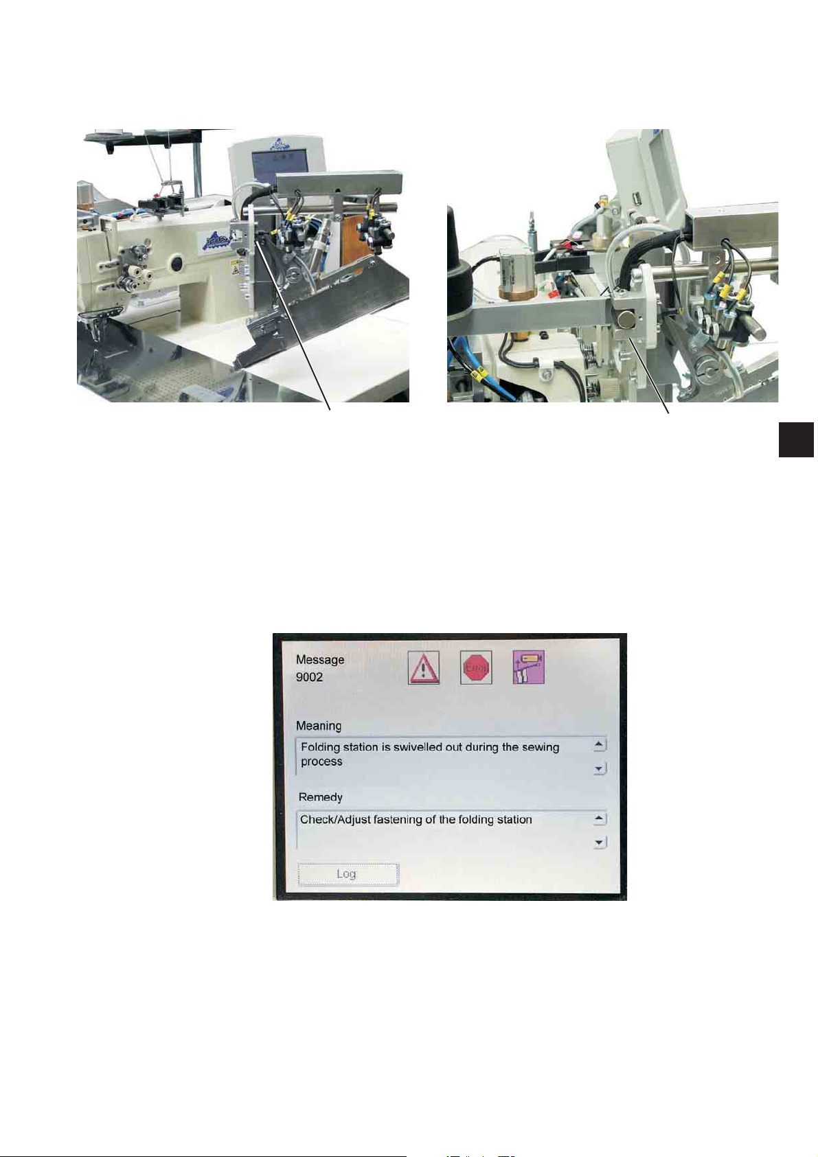
2.1 Swivelling the folding station aside
1
For work at the sewing point (threading the needle threads, needle
change etc.) the entire folding station with folder and laser lamps can
be swivelled to the right.
–
Swivel the entire folding station 1 with folder to the right.
The sewing point is freely accessible.
Note:
When the sewing unit is switched on a
safety message is indicated in the display of the control panel.
2
1
Folding station swivelled out
Swivelling the folding station back
–
Swivel the folding station 1 back.
ATTENTION !
After having been swivelled back the folding station must snap in
catch 2.
7
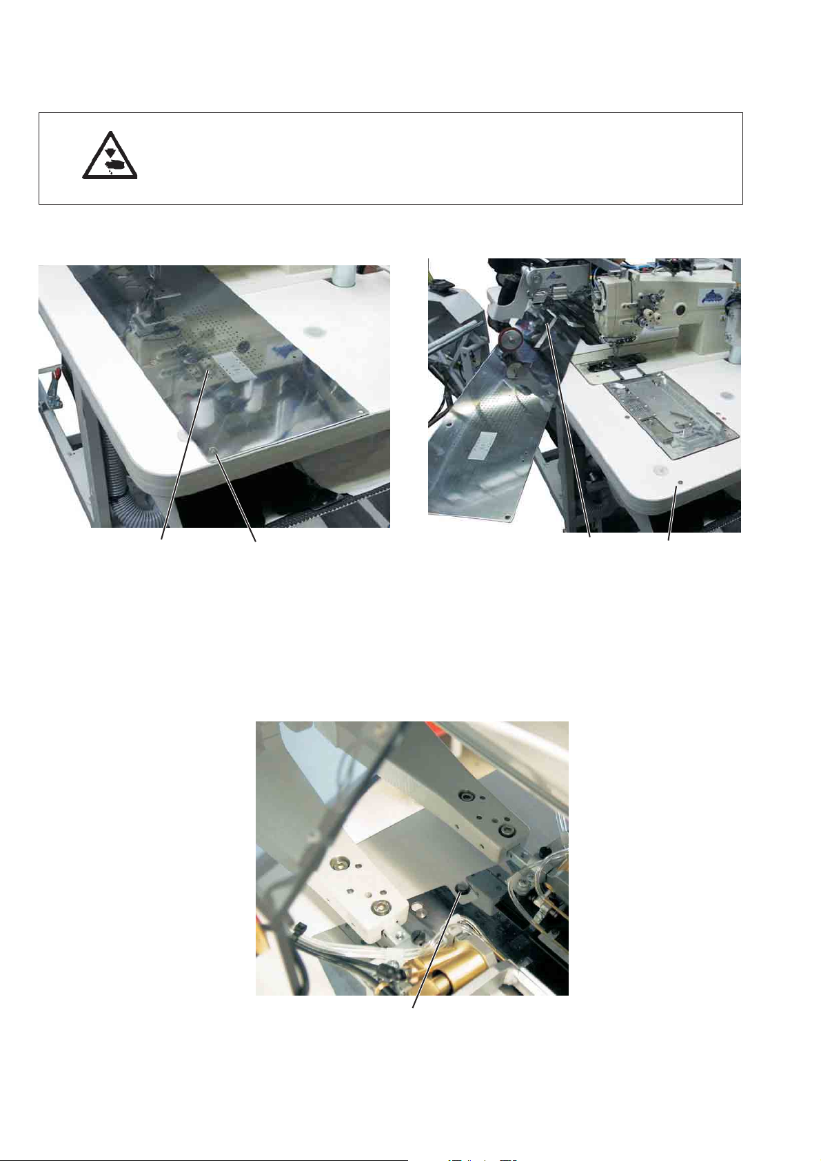
2.2 Removing the fabric sliding sheet
Caution: Risk of injury!
Switch the main switch off.
Remove the fabric sliding sheet only with the sewing unit switched off.
–
Switch the main switch off
21
For changing the hook thread bobbins:
–
Lift the fabric sliding sheet 2 at/with the pin 1 and swivel it to the
left.
For complete removing (for maintenance work and adjustments):
–
Lift the fabric sliding sheet at the hind pin 3c completely.
31
3
8

2.3 Needles and threads
Needle system: 2134-85
Recommended
needle size: Nm 90 for thin material
Nm 100 for medium-weight material
Nm 110 for heavy-weight material
High sewing security and good sewability are achieved with the
following
core threads:
–
Two-ply polyester endless polyester core-spun
(e.g. Epic Poly-Poly, Rasant x, Saba C, ...)
–
Two-ply polyester endless cotton core-spun
(e.g. Frikka, Koban, Rasant, ...)
If these threads are not available, the polyester fibre or cotton threads
listed in the table can also be sewn.
Often two-ply core threads are offered by the thread manufacturers
with the same designation as three-ply polyester fibre threads
(3cyl.-spun).This causes uncertainty with regard to twisting and thread
thickness.
When in doubt, unravel the thread and check whether it is twisted 2- or
3-ply.
The label no. 120 on the thread reel of a core thread corresponds e.g.
to the thread size Nm 80/2 (see table values in brackets).
In case of monofilament threads you can use needle threads and hook
threads of the same thickness. The best results are achieved with soft
and elastic threads (software) of the thread thickness 130 Denier.
1
Recommended thread thicknesses:
Needle size Core thread Core thread
Nm
Needle thread Hook thread Needle thread Hook thread
Polyester Polyester Polyester Cotton
endless core-spun endless core-spun
Label No. Label No. Label No. Label No.
90 120 (Nm 80/2) 120 (Nm 80/2) 120 (Nm 80/2) 120 (Nm 80/2)
100 100 (Nm 65/2) 100 (Nm 65/2) 100 (Nm 65/2) 100 (Nm 65/2)
110 75 (Nm 50/2) 75 (Nm 50/2) 75 (Nm 50/2) 75 (Nm 50/2)
Needle size Polyester fibre thre-ad Cotton thread
Nm (3cyl.-spun)
Needle thread Hook thread Needle thread Hook thread
90 Nm 80/3-120/3 Nm 80/3-120/3 Ne
100 Nm 70/3-100/3 Nm 70/3-100/3 Ne
110 Nm 50/3-80/3 Nm 50/3-80/3 Ne
50/3-70/3 NeB50/3-70/3
B
40/3-60/3 NeB40/3-60/3
B
40/4-60/4 NeB40/4-60/4
B
9
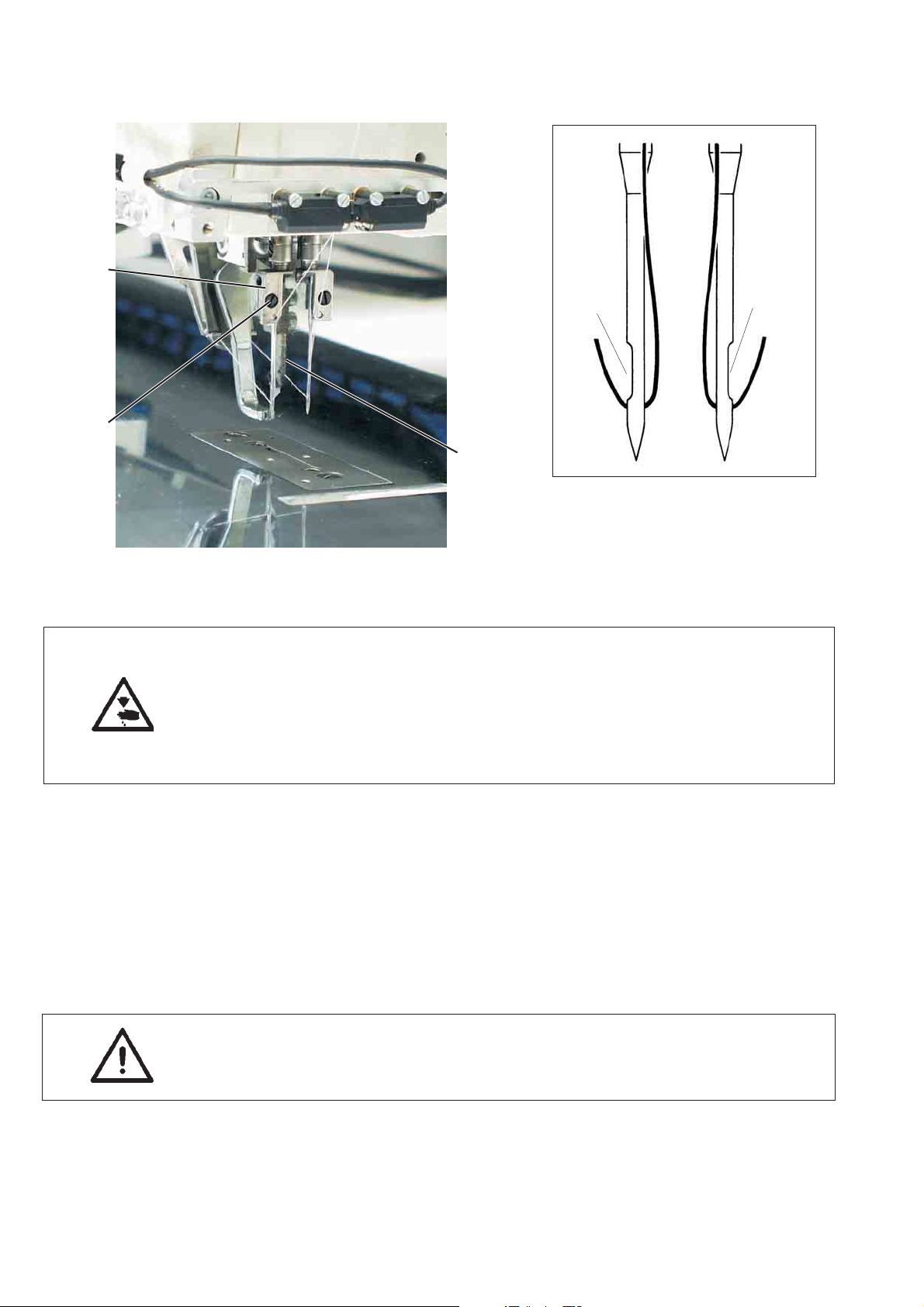
Needle change
1
4
5
2
3
Caution: Risk of injury!
Switch the main switch off.
Change the needles only when the main switch is switched off.
Risk of cuts!
Do not reach into the area of the centre knife 3 when changing the
needles.
10
–
Swivel the folding station aside (see chapter 2.1)
The needles are freely accessible.
–
Loosen screw 2 and remove needle from needle holder 1.
–
Push a new needle into the drill-hole of needle holder 1 as far as it
will go.
ATTENTION!
Seen from the operator’s side of the sewing unit the hollow groove
4 of the left needle must point to the left and the hollow groove 5 of
the right neele to the right (see sketch).
–
Tighten screw 2.
ATTENTION!
After the changeover to another needle size the needle protection at
the hook has to be readjusted (see service instructions).
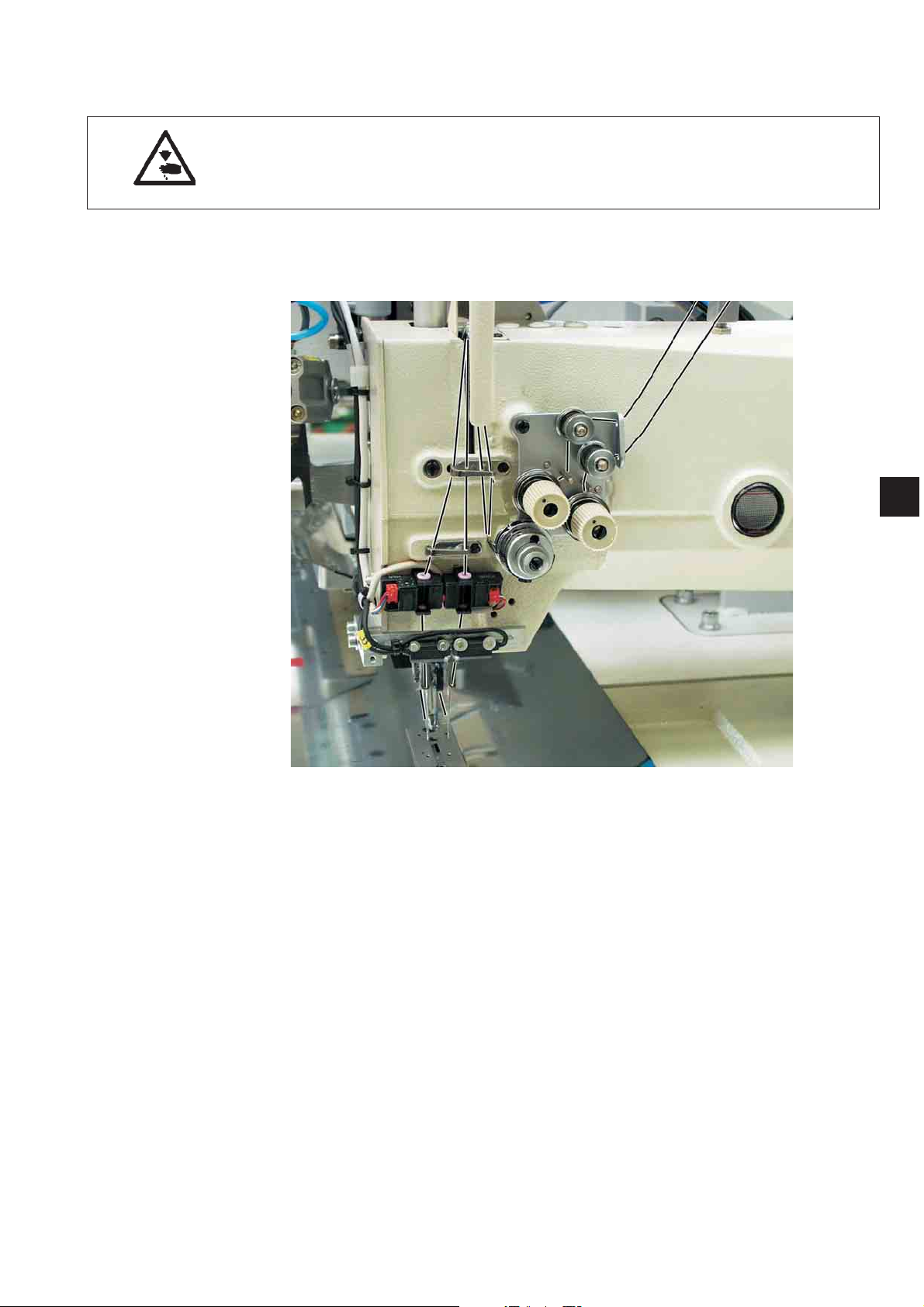
2.4 Threading the needle thread
Caution: Risk of injury!
Switch the main switch off.
Thread the needle threads only with the sewing unit switched off.
See the illustration for threading the needle threads
1
11
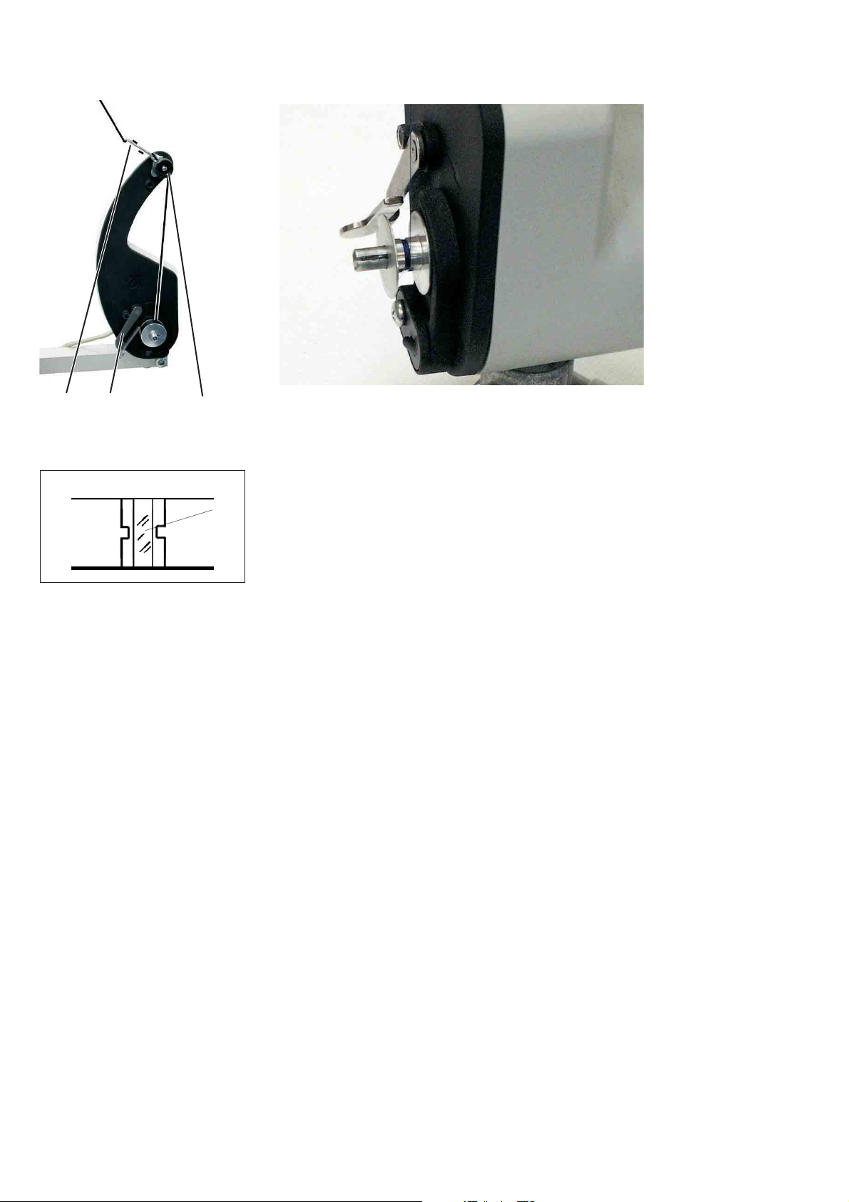
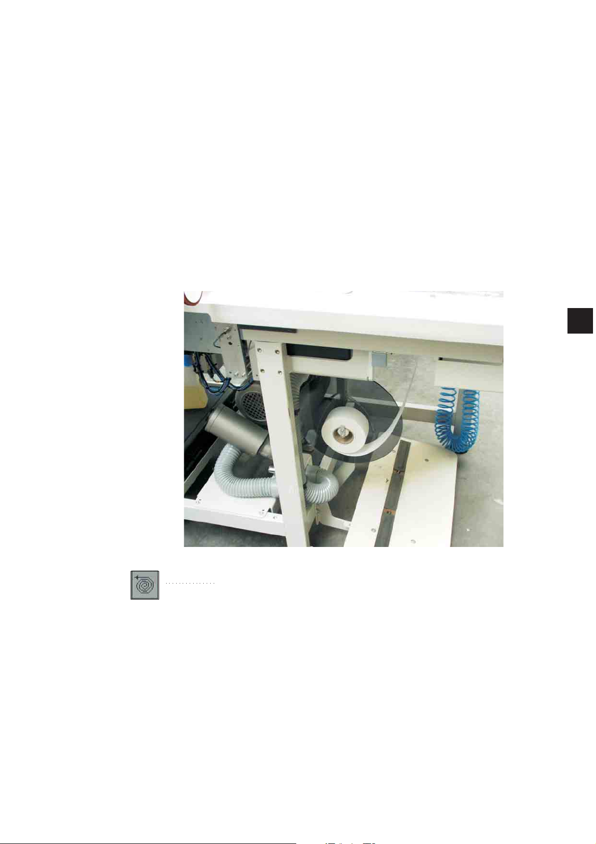
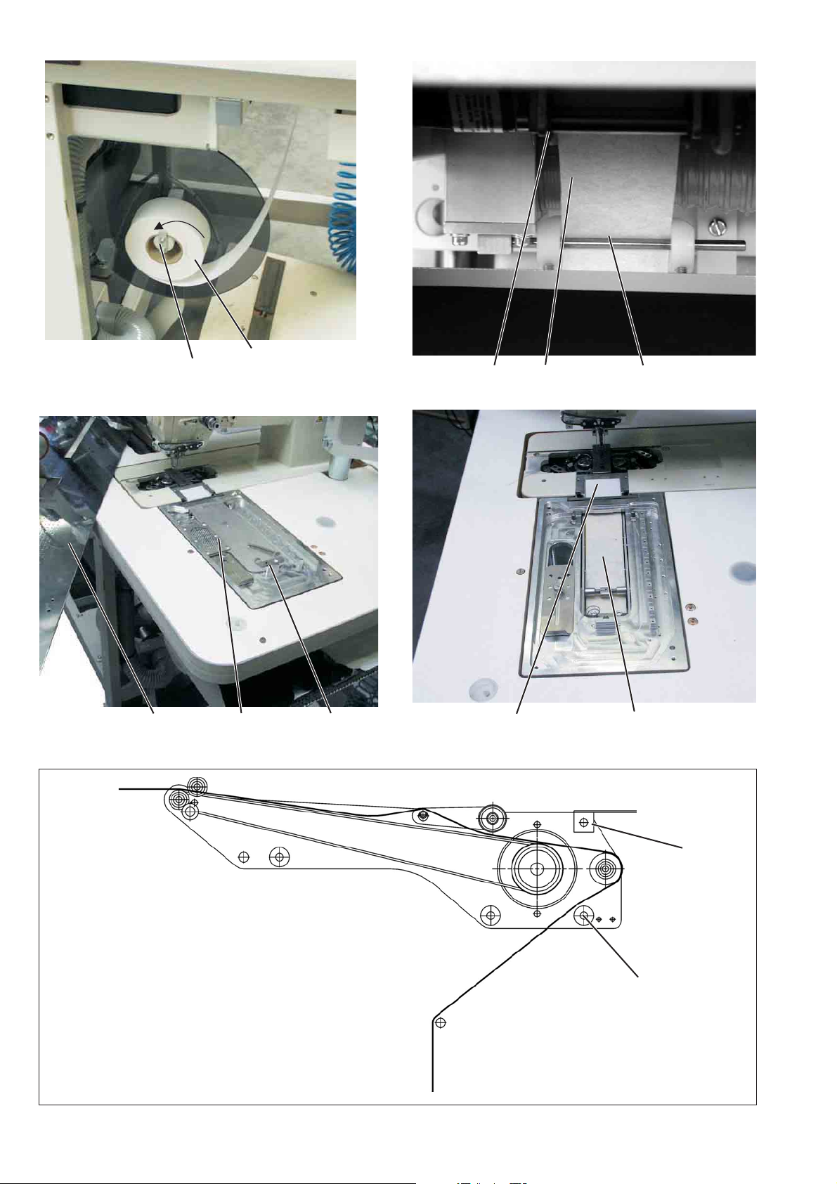
2.5 Winding up the hook thread
32 1
The separate winder allows to wind up up the hook threads
independent of the sewing process.
4
–
–
–
–
–
–
–
Remove thread remainders from the bobbin hubs before winding
up.
Put the thread reel on the thread reel holder.
Thread the thread through the drill-hole 1 of the unwinding arm.
Guide the thread through the guide 3.
Guide the thread through the bobbin thread tension 1.
Prewind the thread in the central supply groove of the bobbin hub
in clockwise direction.
The full supply groove guarantees a secure winding start, even in
case of monofilament threads.
With the thread supply in the supply groove it is ensured that the
pocket opening can be safely finished after the remaining thread
monitor has produced the message “bobbin empty”.
The reflecting surface 4 of the bobbin hub has to be kept clean.
Press the bobbin retainer 2 against the bobbin hub.
The winder starts.
After reaching the set bobbin filling quantity the winder stops
automatically.
See the service instructions for setting the bobbin filling quantity.
12
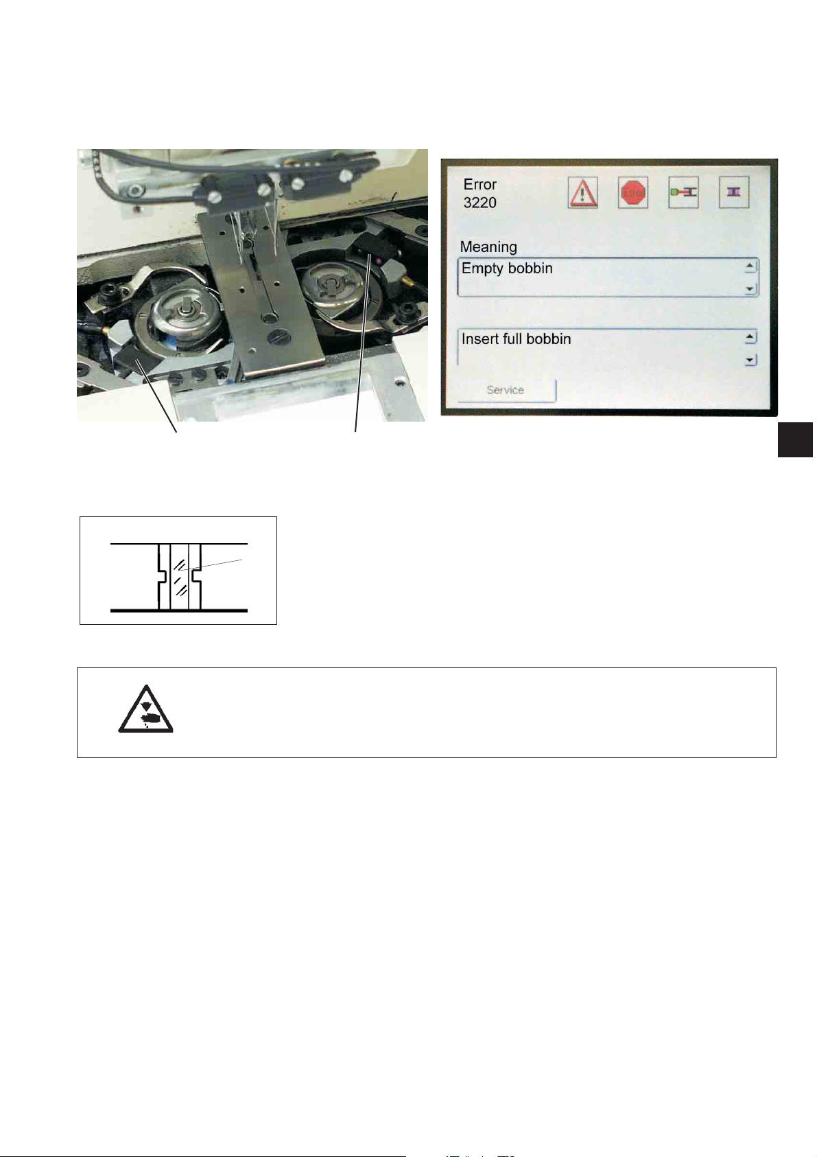
2.6 Remaining thread monitor
The remaining thread monitor supervises the left and right hook thread
bobbin with the infrared reflected light barriers 1 and 2.
21
–
When the bobbin is empty, the light beam emitted by light barrier 1
or 2 is reflected at the free reflecting surface 3 of the bobbin hub.
–
The display of the control unit indicates the message shown in the
right picture.
–
3
The remaining thread in the supply groove of the bobbin hub
guarantees that the pocket opening is safely finished.
The transport carriage stops in its rear end position.
Caution: Risk of injury!
Switch the main switch off.
Clean the lenses of the light barriers only with the sewing unit
switched off.
–
Switch the main switch off.
–
When changing the bobbin always clean the lenses of the light
barrier with a soft cloth.
–
Switch the main switch on.
–
Start the new sewing process.
1
13
2.7 Slanted pocket opening (optional)
The 100/68 is optionally equipped with an automatic corner knife
station guaranteeing a precise incision of the corners of slanted
pockets.
For this purpose the machine head is equipped with disengageable
needle bars.
Corner knife station
The adjustment of the corner knives as to the pocket length is
programmable and is realized by a step motor.
The slanted pocket corners result from the offset of the two seam rows
programmable in steps of 1 mm.
The programmable pocket corner incision - adjustable via two step
motors - is freely selectable for the seam beginning and the seam end
and amounts to max. +/- 10 mm in relation to the second seam.
The lateral distance of the corner knives to the seam is manually
adjustable.
The whole unit can be folded out for adjusting and servicing.
2.7.1 Swivelling the corner knife station in and out
14
321
The corner knife station 1 can be swivelled out completely.
Caution: Risk of injury!
Switch the main switch off.
Swivel the corner knife station out only with the sewing unit
switched off.
Swivelling the corner knife station out
–
Push the rear corner knife support 3 (seam beginning) to the left.
–
Pull catch 2 down.
–
Swivel the corner knife station 1 to the left.
The knives are accessible for adjusting and servicing.
1
21
Swivelling the corner knife station in
–
Swivel the corner knife station 1 back under the sewing unit.
–
Pull catch 2 down.
–
Swivel the corner knife station 1 in completely.
–
Release catch 2.
ATTENTION: Risk of breakage!
The holder 2 must snap in audibly.
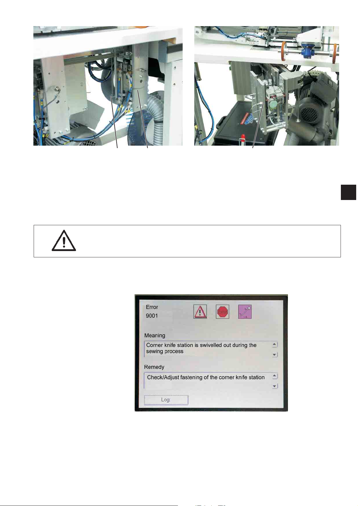
Note:
If the corner knife station is swivelled out with the sewing unit switched
on, the following message appears:
1
1
15
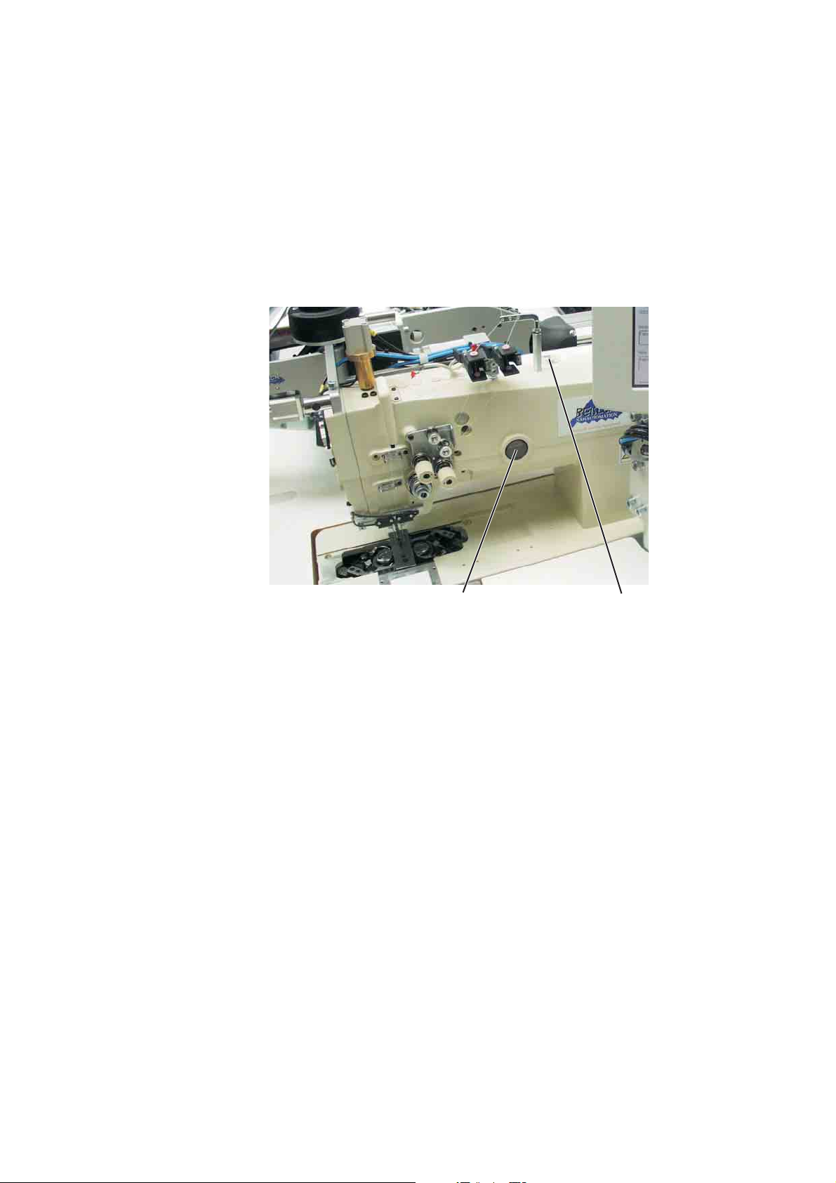
3. Switching on - Starting the sewing process - Program stop Switching off
21
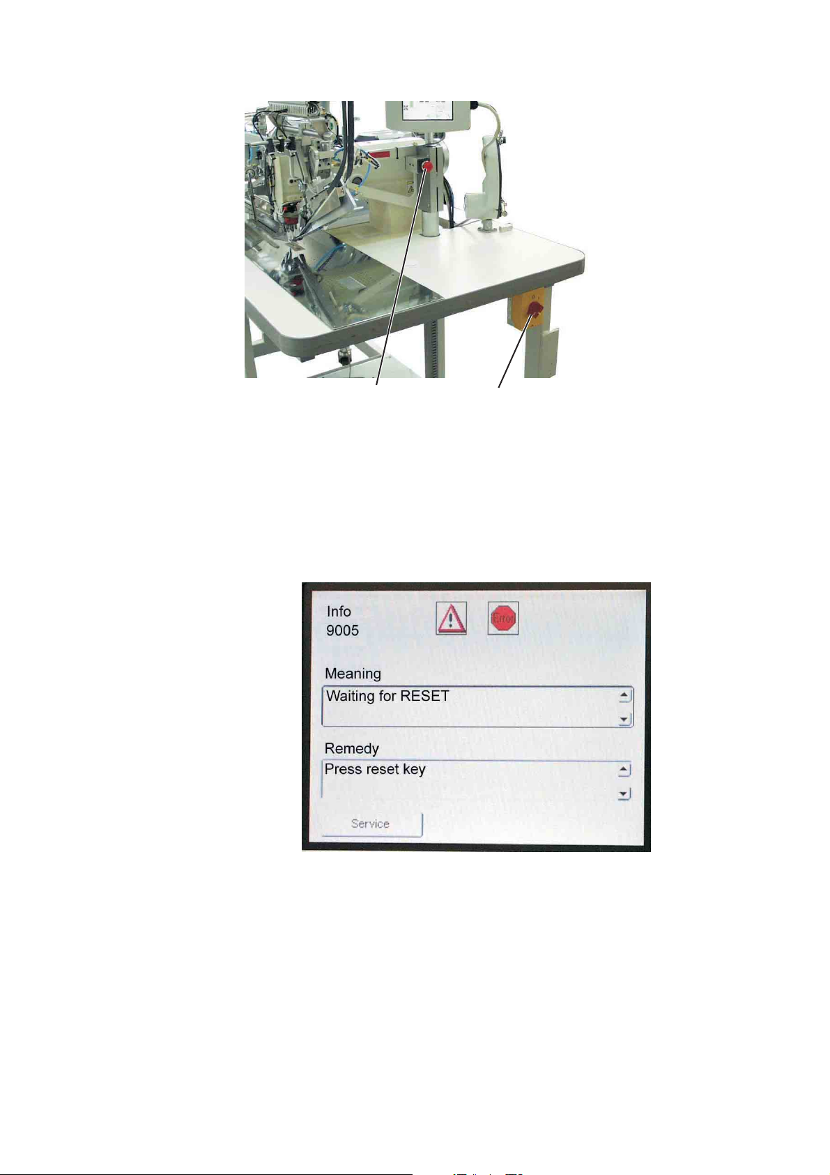
3.1 Switching on
–
switch the main switch 1 on (turn in clockwise direction).
The control loads the machine program.
The start screen appears in the display of the control panel and
indicates the following message:
–
Press the program stop switch 2.
If the transport clamps are not at the reference position, a
reference run is made.
16

3.2 Reference position
Reference position
The reference position is necessary to reach a defined initial position.
When the sewing unit is switched on, the control checks whether the
transport carriage is in its rear end position.
If this is not the case, the display shows the following message:
1
Caution: Risk of injury !
Risk of bruises between folder and deposit table.
–
–
3.3 Starting the sewing process
–
–
–
The individual steps of the feeding process can be cancelled.
Press the program stop switch.
The reference run starts.
The transport carriage moves to its rear end position.
The display changes over to the main screen of the sewing unit.
Actuate the central foot switch.
By actuating the central foot switch repeatedly the different steps
of the feeding process are started one after the other.
The individual steps depend on the working method and on the
equipment of the sewing unit.
For feeding corrections:
Actuate the right foot switch or press the reset key.
The last step of the feeding process is cancelled.
The workpiece can be fed anew.
Step the central foot switch to the front.
The sewing process starts.
17
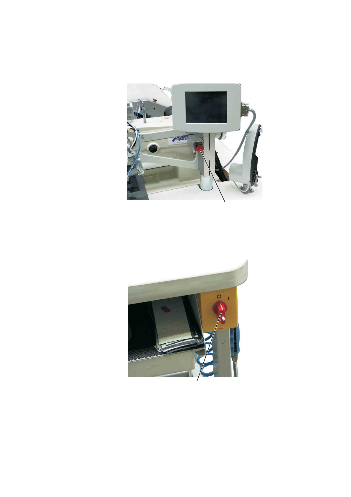
3.4 Program stop
For an immediate switch-off of the sewing unit in case of operating
errors, needle breakage, material accumulation etc. the safety system
of the 100/68 will react as follows:
–
Press program stop 1.
The sewing process is stopped immediately.
3.5 Switching off
1
–
Switch the main switch 2 off (turn counter-clockwise).
18
2

4. Working methods
The individual working methods for trousers and men’s jackets are
described on the following pages.
The description is structured as follows:
Feeding positions
This item indicates the feeding points for the different workpieces (e.g.
left and right parts).
Aligning the positioning aids
Here you will find a description how to adjust and align the positioning
aids (e.g. positioning marks, marking lamps, guides etc.).
Feeding and starting the sewing process
Here you will find a list of the individual feeding steps with
practice-oriented examples.
1
ATTENTION!
The steps of the feeding process are dependent on the equipment of
the respective sewing unit.
So the feeding steps described in the examples apply to sewing units
with the same equipment only.
Caution: Risk of injury!
Do not reach under the downholder, the transport clamp and the folder
during the feeding process.
19

4.1 Working method “Production of trousers”
Possible processing variants
–
Front trousers pockets with pocket bag positioned underneath
–
Hind trousers pockets with or without flap, with pocket bag
positioned underneath
–
Hind trousers pockets with or without flap, with automatically fed
reinforcement strip
Feeding method
Example: Hind trousers without flap, with pocket bag positioned
underneath
1st step:
–
Select the pocket program at the control panel
–
Push the pocket bag under the pocket bag clamp 1 and position it
at the markings 2.
For example adhesive strips fitted on the fabric sliding sheet may
serve as markings.
2nd step:
–
Position the hind trousers at the “central positioning point” 5 and
the marking 4.
–
Actuate the central foot switch.
The hind trousers is clamped by the fabric downholder 3.
–
Smooth out the clamped hind trousers in the dart area.
–
If the machine is additionally equipped with vacuum:
Actuate the left foot switch.
The vacuum is switched on.
3rd step:
–
Step on the central pedal.
The transport clamps move to the front and lower on the
workpiece.
–
Position the piping strip 6 on the transport clamps flush with the
front edges 7.
The aligning of the various kinds of piping on the transport clamps
is described more exactly in the following.
See “Positioning of piping strips”.
–
Actuate the central foot switch.
The folder 8 lowers.
–
Actuate the central foot switch once again.
The sewing process starts.
20

1
2
1
3
4
5
6
8
7
21
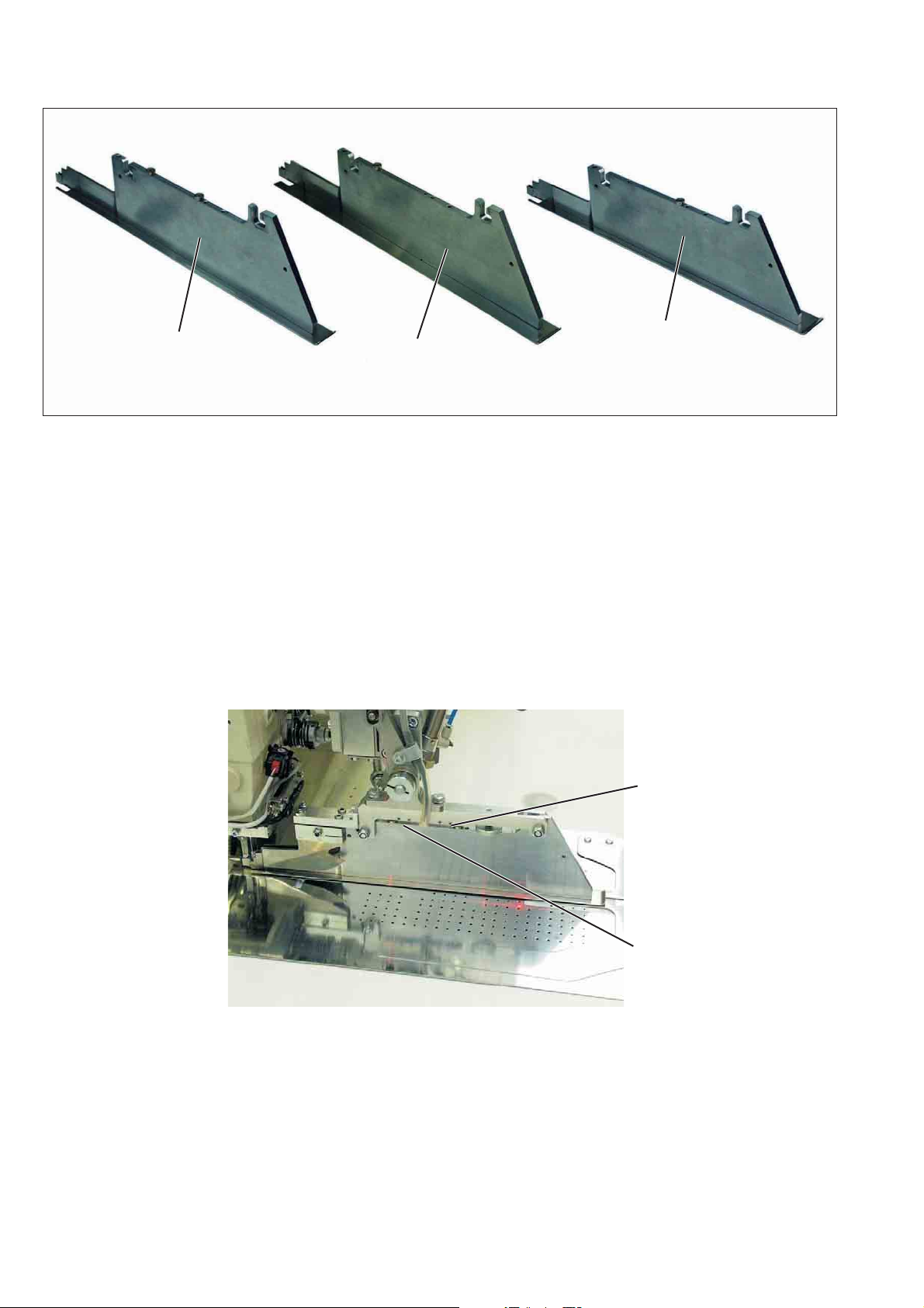
5. Quick clamp adjustment and folder monitoring
1
The lateral position of the transport clamps is influenced by the
solenoid switches SC103 and SC106.
According to the equipment the magnets are fitted on the folders in
different positions.
Depending on the selected folder the clamps are adjusted
automatically.
1 = Folder for double piping
2 = Folder for single piping, left
3 = Folder for single piping, right
2
3
SC103
22
SC106
6. Function and operation of the optional equipment
This chapter describes the function and operation of the most
important
optional equipment.
6.1 Tape feeding unit with automatic trimming and tape monitor
The step motor- and length-controlled tape feed with automatic
trimming transports the reinforcement strip under the pocket opening
and cuts it off at the seam end (e.g. when sewing inside and outside
pockets of men’s jackets).
A sensor supervising the tape feed is integrated in the tape feeding
unit.
The whole sequence is realized within the machine time
so that there are no further feeding or secondary processing times.
If the tape is not pulled during the sewing process, e.g. in case of
accumulation or wrong threading, a message is produced by the
control.
1
Activating and switching the tape feed on
–
Activate the tape feed at the control panel in the menu item “Seam
functions”.
–
Tap the icon.
23
21
54 3
24
98 7
11 10
5
3

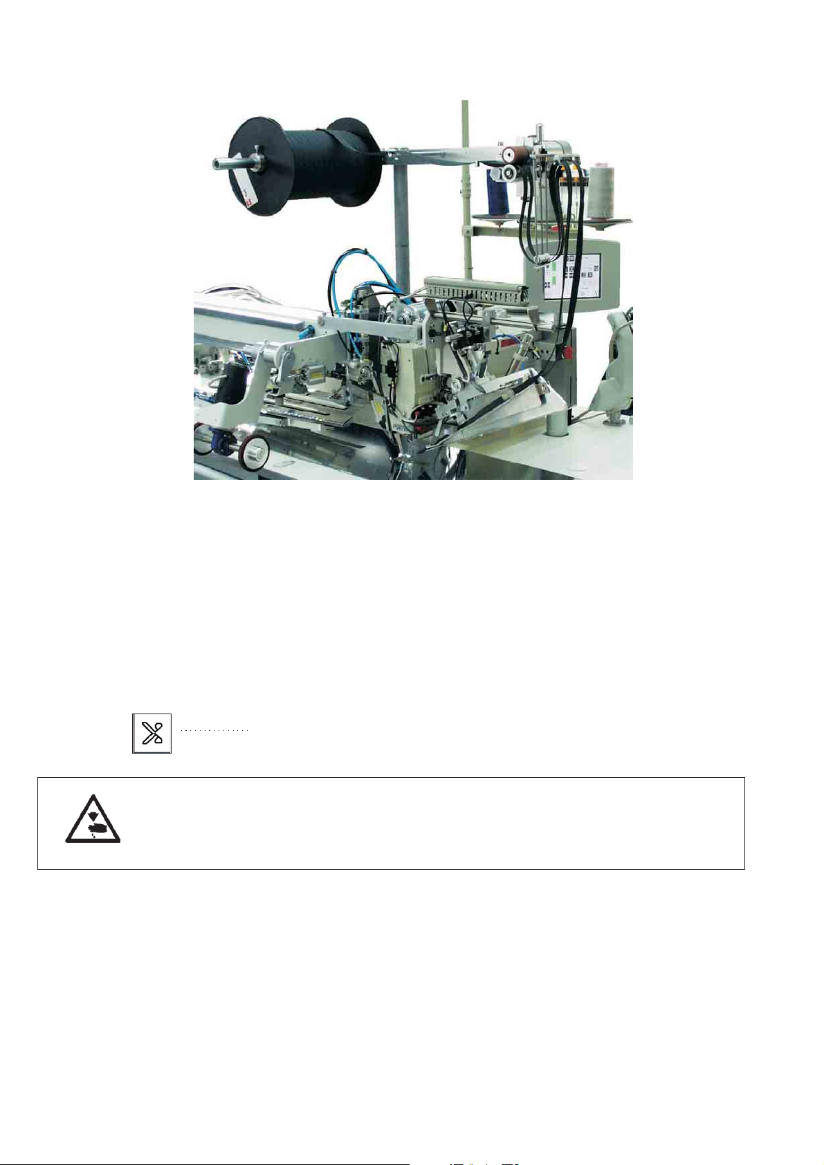
Inserting the reinforcement strip
–
Put roll 1 on the tape roll holder 2.
The full roll must rotate in the indicated arrow direction
(counter-clockwise) when unwinding.
–
Guide the reinforcement strip via guide 5.
–
Swivel the fabric sliding sheet 9 aside.
–
Press slide 7 backwards and lift off cover 8.
–
Insert the reinforcement strip in the feeding device according to the
sketch.
–
Swivel the fabric sliding sheet 9 back again.
–
Tap the key.
The reinforcement strip is cut off and moved to the initial position.
Function and operation
Before the next sewing cycle the reinforcement strip is fed forward a
little by the transport roller of the feeding device.
When sewing the pocket opening the reinforcement strip is seized and
sewn in according to the set sewing length.
The tape projection at the seam beginning and seam end can be set in
the menu item “Seam parameters” with the parameters 21 and 22 (see
programming instructions).
1
25
6.2 Endless zipper device
Function
When the zipper halves are pulled by the transport clamps during the
sewing process, the feed rod 6 is pulled upwards by the zipper getting
shorter.
The feed rod switches the zipper feed on and the drive rollers 7 and 8
go on feeding the zipper until the switch rod drops and switches the
feed off again.
Thus it is made sure that there is always enough zipper material
available for sewing.
Activating and switching the zipper device on
–
Tap the key.
The zipper device is activated.
Caution: Risk of injury !
During the swivelling and cutting process.
26
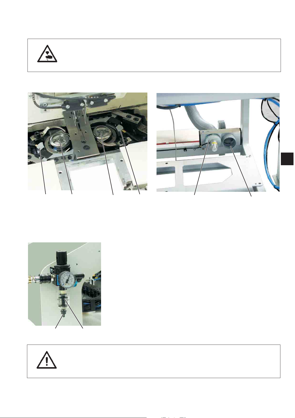
7. Maintenance
7.1 Cleaning
Caution: Risk of injury!
Switch the main switch off.
Carry out maintenance work only with the sewing unit switched off.
1
43 21
A clean sewing unit protects from malfunction!
Clean and check daily:
–
Clean the area around the hooks 2 and 3 with the compressed air
pistol.
–
When changing the bobbin always clean the lenses of the light
barriers 1 and 4
of the remaining thread monitor with a soft cloth.
–
Cleaning of the filter ring 6 at the vacuum valve 5:
Blow out with compressed air pistol.
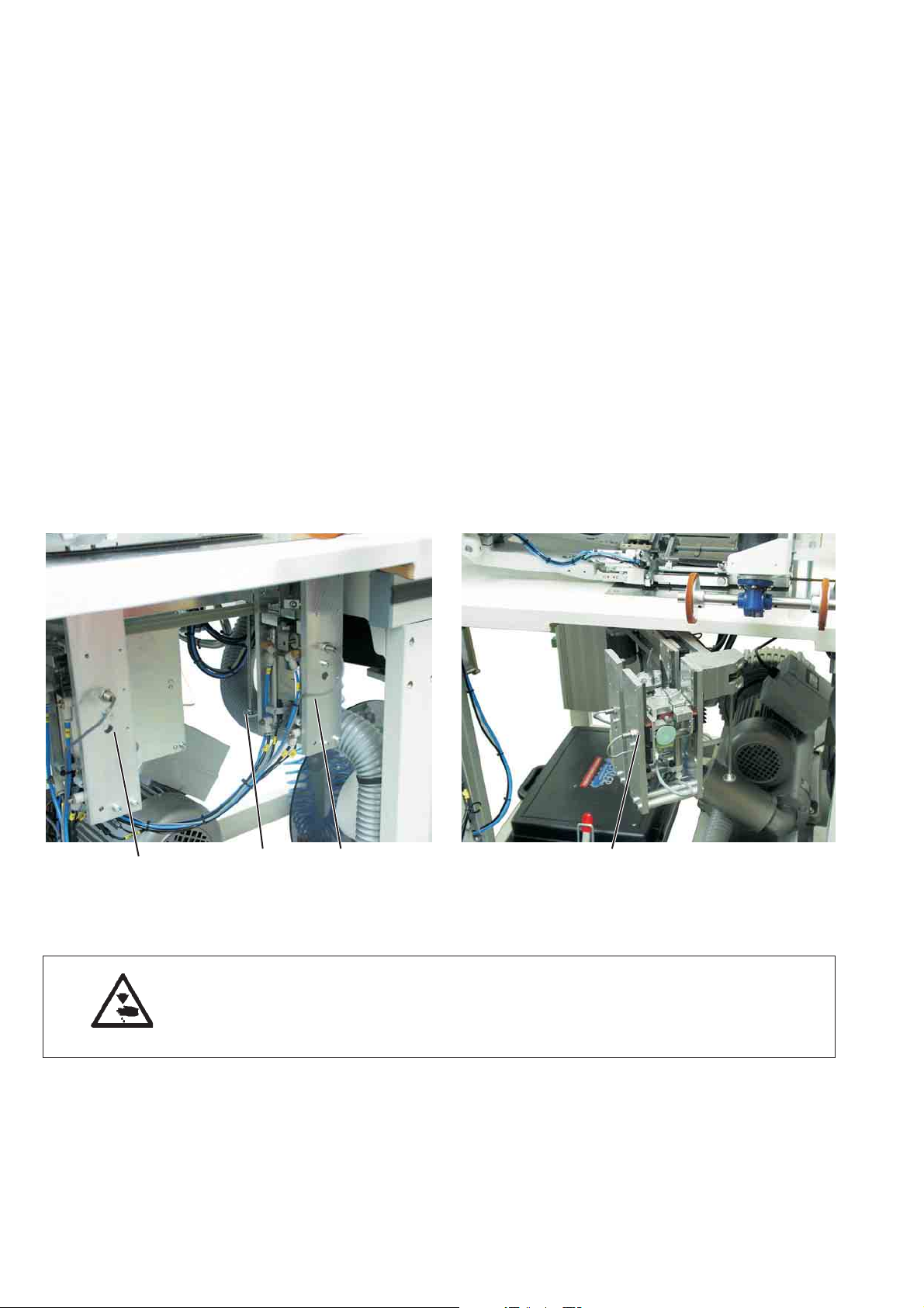
Clean and check daily:
–
Check the water level in the pressure regulator.
The water level must not reach the filter insert.
After screwing in the drain screw 2 blow the water
out of the water separator 1 under pressure.
The filter insert separates dirt and condensed water. After a certain
time of operation
wash the dirty filter tray and the filter insert with benzine and blow
them clean with the compressed air pistol.
21
65
ATTENTION!
Do not use any solvents for washing out the filter tray and the filter
insert!
They destroy the filter tray.
27
7.2 Oil level control
For lubrication of the sewing machine head use exclusively the
lubricating oil
ESSO SP-NK 10.
SP-NK 10 can be bought from the sales office of Beisler GMBH
.
Checking the oil level in the oil reservoir 2 for the lubrication of
the machine head
–
The oil level in the oil reservoir 2 must not drop below the marking
“Min”.
–
If necessary, fill oil through the drill-hole 1 up to the upper marking.
21
28
 Loading...